treated with high-friction inorganic zinc-rich paint … experimental study on slip strength of hsfg...
TRANSCRIPT

An Experimental Study on Slip Strength of HSFG Bolted JointsTreated with High-Friction Inorganic Zinc-Rich Paint
Yohei Koike* and Keiji Terao*
ABSTRACT
Recently for the purpose of cost reduction in construction, rationalization of high-strengthfriction grip bolted joints in plate girder bridges is encouraged. As a method of therationalization, it is proposed to increase the design slip factor specified as 0.4 in theJapanese Specifications for Highway Bridges (JSHB)1). Since it is relatively smallcompared with other countries and the increase of the factor leads directly to the reductionof the number of bolts, high-friction inorganic zinc-rich paint having high slip factor over0.7 was developed through tensile tests in this study.
1. INTRODUCTION
In recent years, in accordance with the enlargement of cross-sections by adoption ofbridges with greater girder spacing, the number of HSFG bolts has been increased, and thesize of splices has been expanded. To reduce the number of bolts, it is proposed to increasethe design slip factor specified as 0.4 in JSHB. While the shift of the design method fromallowable stress design method to performance based design method, the increase of slipfactor is expected to contribute to rationalization of bolted joint. As shown in Table 1,although various values are already specified according to the conditions of the frictionsurfaces in the design criteria of other countries, slip factor specified in the JSHB isuniformly 0.4, and the value in Japan is relatively small compared with one of othercountries. On the other hand, increase of slip factor is expectable with the development ofthe paint technique in recent years. With these backgrounds, many tensile tests using specimens with inorganic zinc-rich paintwere carried out, and the conventional zinc-rich paint was improved and new high- frictionpaint has been developed. This paint has the same functions, such as the corrosionprotection performance and the working performance, as that of conventional one.
2. EXPERIMENT PROCEDURE
As shown in Fig. 1, a tensile specimen has the bolt arrangement of one-line two-rows, andwas designed so that the base plates and the splices did not yield before load reached slipstrength. The grade of the steel material is SM490Y and M22(F10T) was used for high-strength bolts. Inorganic zinc-rich paint was applied to the friction surfaces after shot-blasting. A painting scene is shown in Photo 1.
* Yokogawa Bridge Corp. Research Laboratory No.27,Yamano-cho,Funabashi-shi,Chiba-ken,273-0026,Japan

As shown in Table 2, experiments are 32 cases intotal, and the main parameters are paintcomposition, film thickness and surface roughness.In consideration of the dispersion, three specimenswere tested in each case. High-strength bolts were fastened by 60% of bolttension specified in JSHB at first, and thentightened by 100 % (= 225.5kN). The tension in thefixed side was increased by 10% so that a slipmight not occur. In consideration of the relaxation of high-strengthbolts, the experiments were carried out more thanseven days after bolts were tightened. Thedisplacement between base plates and the axialforce of bolts in case 23-32 were measured, and
5580
555
5580
55
200
385
200
785
10016 32 16
Fig. 1 A tensile specimen
Table 1 International comparison of slip factor
slip factor the treatment or the conditionof the friction surface slip factor the treatment or the condition
of the friction surface
0.50 shot-blasting or grid-blasting 0.33 the surface with clean mill scale
0.50 zinc based metal spray guaranteed the slip factor0.5 at least after shot-blasting or grid-blasting 0.50 class A coating after blasting
0.30 the surface removed loose scale after cleaned bywire brushing or flame cleaning 0.50 blasting
0.20 none 0.40 class B coating after blasting0.40 the rough surface with galvanization
0.33 the surface with clean mill scale 0.30 the surface with clean mill scale
0.40 the surface removed mill scale and loose scaleand after exposure outdoors 0.50 sand-blasting or flame cleaning
0.50 shot-blasting or grid-blasting 0.40~0.50* zinc based metal coating after sand-blasting
0.50 inorganic zinc-rich painting with thicknessunder 60 micrometer 0.30~0.45* zinc based organic coating after sand-blasting
0.35 organic zinc-rich painting with thickness under60 micrometer 0.35 the rough surface with galvanization
0.40 blasting on the galvanized surface with thicknessover 50 micrometer
0.45 the surface removed mill scale and loose scaleand after exposure outdoors 0.50 shot-blasting or grid-blasting
0.50 shot-blasting or grid-blasting 0.50 flame cleaning twice0.35 inorganic zinc-rich painting 0.50 alkali silica zinc powder painting
0.40 the rough surface removed mill scale0.40 thick inorganic zinc-rich painting
●the Japanese Specifications for Highway Bridges1) (2002)
●Eurocode2) (1997)
●ISO4) (1997)
●AASHTO3) (1994)
●BS6) (1982)
●SIA5) (1979)
The value of * is depened on the process of the painting
●DIN7) (1990)

load was increased linearly until a major slip occurred. An experiment setup is shown inPhoto 2.
3. EXPERIMENT RESULTS
An experiment result is shown in Fig. 2. The slip factor was calculated using equation (1)as shown below.
Nnm
Pslip
⋅⋅=µ (1)
µ :slip factor Pslip :major slip load m :the number of bolts ( =2 ) n :the number of friction surfaces ( =2 ) N :initial bolt tension ( =225.5kN )
Table 2 Experiment cases
casetarget base platefilm thickness
(μm)
target splicefilm thickness
(μm)
targetsurface roughness
(μmRz)curing period main parameters
1 - 4 20 75 80 2 weeks indoors pigment5 - 7 20 75 80 2 weeks indoors zinc particle size8 - 11 20 75 80 2 weeks indoors resin material
12 - 15 20,75 75 80,100 2 weeks indoorszinc particle sizesurface roughness
film thickness16 - 17 75 75 80 2 weeks indoors mix proportion18 - 22 75 75 80 2 weeks indoors pigment23 - 32 75 75 80 7 weeks indoors hardened pigment
Photo 1 View of painting Photo 2 View of experiment

A slip factor was not significantly influenced by zinc particle size or resin material, andwas improved greatly by hardened pigment. This result is expected to originate that theshear capacity between coating films increased. The slip factor of case 29 was themaximum and the average was 0.783.
4.APPLICATION OF HIGH-FRICTION PAINT
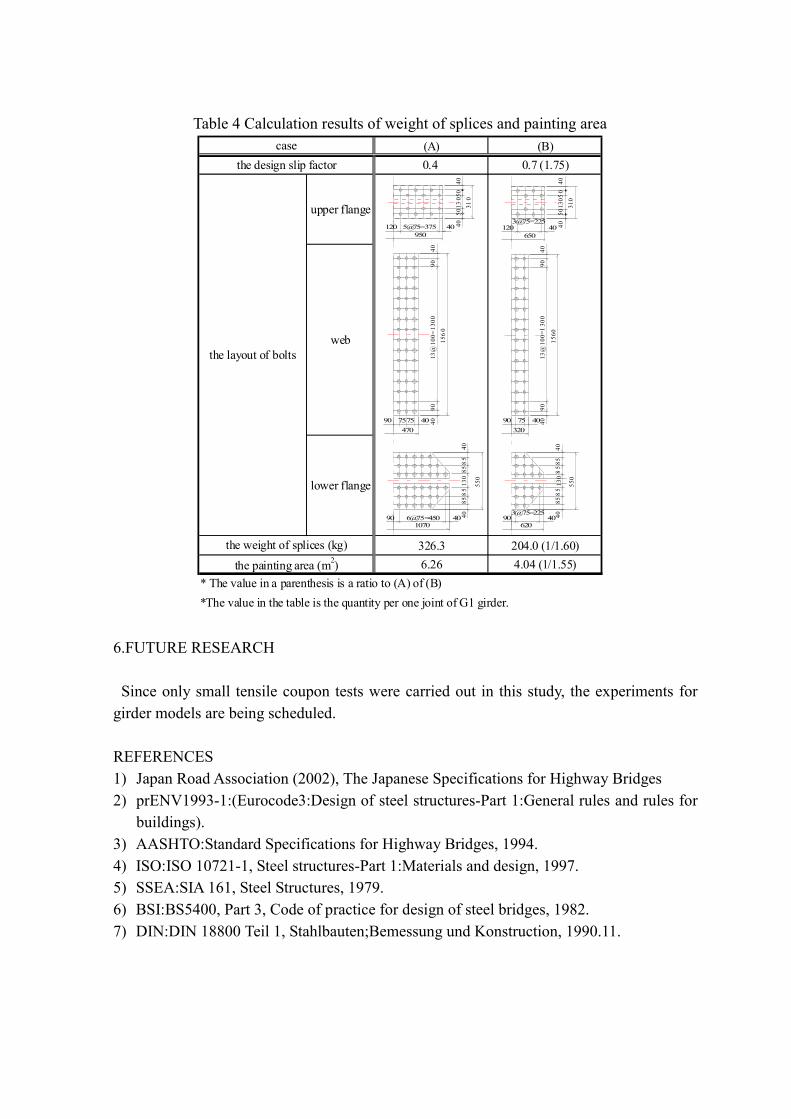
Since the allowable force per high-strength bolt can be improved by increasing slip factor,it becomes possible to reduce the number of high-strength bolts and the size of spliceswhen this developed paint is applied to actual bridges. The tentative calculation wasperformed in order to investigate how bolt joints can be rationalized by using this paint.The example bridge is the simple composite bridge with 4 main I-section girders shown inFig. 3. Although the maximum slip factor was approximately 0.8 according to the experimentresults, the tentative calculation was done by setting the slip factor to 0.7 by taking safetyinto consideration. The calculation result of the number of high-strength bolts is shown in Table 3 and Fig. 4,and of the weight of splices and the painting area is shown in Table 4. As compared withthe conventional design, the number of high-strength bolts can be reduced by about 40%by increasing the design slip factor to 0.7. Furthermore, the size of splices becomes smaller,the painting area and weight of splices can also be reduced by about 40%. Therefore, not
0.3
0.4
0.5
0.6
0.7
0.8
0.9
1.0
0 1 2 3 4 5 6 7 8 9 10 11 12 13 14 15 16 17 18 19 20 21 22 23 24 25 26 27 28 29 30 31 32 33
Expriment case
Slip
fact
or μ
○ :slip factor calcurated using the specified bolt axial tension ● :slip factor calcurated using the bolt axial tension just before the experiments :the average of slip factor in each experiments
change of pigment
change of zinc particle size
change of resin material
change of zinc particle size,surface roughness and film thickness
change of mix propotion
change of pigment
change of hardened pigment
using the hardened pigment
Fig. 2 Result of experiments

only the amount of painting in factories becomes smaller, but work efficiency in field isalso improved. These values are almost decreased in proportion to the increment of slipfactor.
5.CONCLUSIONS
Based on the results, the main conclusions are drawn as follows:(1) High-friction inorganic zinc-rich paint having high slip factor over 0.7 was developed
thorough tensile tests.(2) In order to increase slip factor, use of hardened pigment was most effective.(3) The number of high-strength bolts, painting area, and weight of splices can be reduced
by about 40% by increasing the design slip factor to 0.7 as a result of tentativecalculation.
Fig. 3 General dimensions of the example bridge
3618
48
32
12
8
0
20
40
60
80
100
120
0.4 0.7the design slip factor
num
ber o
f bol
ts
upper flange
web
lower flange
Fig. 4 The number of bolts in each member
Table 3 Calculation results of the number of bolts required
case (A) (B)the design slip factor 0.4 0.7 (1.75)
the allowable force of high-strength bolt (kN) 96 168the design bending moment (kN・m)
the design shear force (kN)the number of bolts in upper flange 12 8
the number of bolts in web 48 32the number of bolts in lower flange 36 18
the total number of bolts 96 58 (1/1.66)
*The value in the table is the quantity per one joint of G1 girder.*The allowable force is the value per two friction surfaces
* The value in a parenthesis is a ratio to (A) of (B)
3213411
6.FUTURE RESEARCH
Since only small tensile coupon tests were carried out in this study, the experiments forgirder models are being scheduled.
REFERENCES1) Japan Road Association (2002), The Japanese Specifications for Highway Bridges2) prENV1993-1:(Eurocode3:Design of steel structures-Part 1:General rules and rules for
buildings).3) AASHTO:Standard Specifications for Highway Bridges, 1994.4) ISO:ISO 10721-1, Steel structures-Part 1:Materials and design, 1997.5) SSEA:SIA 161, Steel Structures, 1979.6) BSI:BS5400, Part 3, Code of practice for design of steel bridges, 1982.7) DIN:DIN 18800 Teil 1, Stahlbauten;Bemessung und Konstruction, 1990.11.
Table 4 Calculation results of weight of splices and painting area(A) (B)0.4 0.7 (1.75)
upper flange
web
lower flange
326.3 204.0 (1/1.60)6.26 4.04 (1/1.55)the painting area (m2)
* The value in a parenthesis is a ratio to (A) of (B)*The value in the table is the quantity per one joint of G1 girder.
the layout of bolts
casethe design slip factor
the weight of splices (kg)
120 5@75=375 40950
4050
130
5040
310
4090
13@
100=
1300
9040
156
0
470
408
585
130
85
8540
550
90 6@75=450 401070
90 7575 40 90 75 40
1203@75=225
40650
405
013
050
4031
0
4090
13@
100=
130
090
40
1560
320
4085
85
130
85
8540
550
903@75=225
40620