treball final de grau - dipòsit digital de la universitat de...
TRANSCRIPT

Treball Final de Grau
Tutor/s
Dr. Joan Llorens Llacuna Departament Enginyeria Química
Xavier Fragua Fernandez Alucha Recycling Solutions
Phenolic fraction recovery from pyrolysis oil obtained from paper sludge.
Obtención de la fracción fenólica de aceite pirolítico proveniente de lodos de papel.
Álvaro González Rivas Enero del 2016


Aquesta obra estasubjecta a la llicència de: Reconeixement–NoComercial-SenseObraDerivada
http://creativecommons.org/licenses/by-nc-nd/3.0/es/


“Fortune favors the prepared mind.”
Louis Pasteur
Me gustaría dedicar y agradecer este trabajo a todas las personas que lo han hecho posible
y que me han ayudado durante estos meses:
En primer lugar, a Xavier Fragua e Ignacio Lopez; por darme consejos, indicaciones y
pautas a seguir durante estos meses en Alucha y por dedicar gran parte de su tiempo a acabar
de pulir este proyecto.
También me gustaría agradecer al resto de miembros de Alucha: Hans Cool, Gijs Jansen,
Carlos Ludlow, Marina Torrens y Anton Bijl, por hacer que mi paso por Alucha haya sido una
gran experiencia y por todos los momentos compartidos.
En último lugar, y no por ello menos importante, me gustaría agradecer a mi familia y
amigos todo el apoyo que me han dado en los buenos ratos y, sobre todo, en los no tan
buenos. Sin vosotros no habría llegado hasta aquí.
Gracias


REPORT


Phenolic fraction recovery from pyrolysis oil obtained from paper sludge 1
CONTENTS
1. SUMMARY 3
2. RESUMEN 5
3. INTRODUCTION 7
3.1. Biomass 7
3.2. Pyrolysis process 8
3.3. Pyrolysis oil 9
3.4. Different applications of bio-oil 11
3.4.1 Energy valorization 12
3.4.2 Chemicals from pyrolysis oil 12
3.5. Paper sludge as feedstock for pyrolysis oil 13
3.6. Chemicals from paper sludge pyrolysis oil 14
4. OBJECTIVES 17
5. CHEMICALS FROM PYROLYSIS OIL 18
5.1. State of art 18
5.1.1 Acetic acid obtainment 18
5.1.2 Hydrogen production 19
5.1.3 Bio-ethanol production 20
5.1.4 Phenolic components 21
5.2. Phase separation 21
5.2.1 Solvent extraction 22
5.2.2 Column chromatography 22
5.2.3 Distillation 22
5.3. Selection of the target chemicals to be recovered 23
5.4. Recovery of the phenolic fraction 25

2 González Rivas, Álvaro
5.4.1 L-L extraction using methanol and water 26
5.4.2 Method of separating lignin derived components from pyrolysis oil 27
5.5. Analysis to determine the amount of phenolic fraction present in bio-oil 27
6. BIO-OIL UPGRADING FOR RECOVERING THE PHENOLIC FRACTION 30
6.1. Feedstock 30
6.2. Reactor and condensation system 31
6.3. Experimental procedure 32
6.3.1 Pyrolysis test 32
6.3.2 Solvent extraction 35
6.3.3 Sulfur extraction 36
6.4 Results and analysis 37
6.4.1 Solvent extraction 37
6.4.2 Sulfur reaction 39
6.4.3 Results of the two initial experiments 41
6.4.4 Improvement of sulphur extraction method 42
6.4.5 Results of both sulfur extraction experiments 45
6.4.6 Solvent extraction using a centrifuge 48
7. CONCLUSIONS 55
8. NEXT STEPS AND RECOMENDATIONS 57
9. REFERENCES AND NOTES 59
10. ACRONYMS 61
APPENDICES 63
APPENDIX 1: CHROMATOGRAPHY RESULTS AND FUNCTIONAL GROUP CLASSIFICATION 65

Phenolic fraction recovery from pyrolysis oil obtained from paper sludge 3
1. SUMMARY
The energy of biomass can be obtained by various techniques, such as combustion or by
upgrading it into a more valuable fuel, gas or oil. Biomass can also be transformed into a source
of value-added products for the chemical industry by using different thermochemical
technologies; one of them is fast pyrolysis, which has received extensive interest in recent
years. Fast pyrolysis of biomass is a thermal decomposition process that occurs in the absence
of oxidizing agents. Quick biomass decomposition followed by a rapid vapor condensation
converts biomass into a liquid product known as bio-oil.
For the usage of bio-oil as fuel, its oxygen content must be reduced. On the other hand, if
the intent is to only use it as a chemicals’ source, then the oxygen removal step may not be
necessary. Many oxygen-containing chemicals now are produced from fossil fuels via oxidation
or hydration of olefins to introduce oxygen-containing functional groups. In contrast, these
functional groups are already present in bio-oil.
The first step was to study different processes to obtain chemicals from bio-oil and to
perform characterization analyses of a bio-oil from paper sludge feedstock in order to define its
chemicals. Subsequently, some of the technologies to obtain these chemicals were tested to
see if it was possible to obtain similar results when applying them to the bio-oil obtained from
our pyrolysis process.
At the end of the project an initial approach to the investigation of two methods to recover
the phenolic fraction present in pyrolysis oil was done. These methods are: solvent extraction
using methanol and water and phase separation injecting sulfur dioxide, and both reported
promising results, being able to obtain a final product which can be used as a substitute of
traditional phenol.
Keywords: Pyrolysis oil, phenolic fraction, paper sludge, chemicals, bio-oil, lignin, solvent
extraction, sulfur extraction, refining, bio-fuels.

Phenolic fraction recovery from pyrolysis oil obtained from paper sludge 5
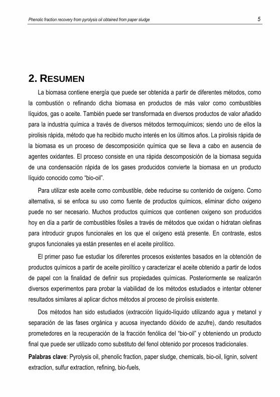
2. RESUMEN
La biomasa contiene energía que puede ser obtenida a partir de diferentes métodos, como
la combustión o refinando dicha biomasa en productos de más valor como combustibles
líquidos, gas o aceite. También puede ser transformada en diversos productos de valor añadido
para la industria química a través de diversos métodos termoquímicos; siendo uno de ellos la
pirolisis rápida, método que ha recibido mucho interés en los últimos años. La pirolisis rápida de
la biomasa es un proceso de descomposición química que se lleva a cabo en ausencia de
agentes oxidantes. El proceso consiste en una rápida descomposición de la biomasa seguida
de una condensación rápida de los gases producidos convierte la biomasa en un producto
líquido conocido como “bio-oil”.
Para utilizar este aceite como combustible, debe reducirse su contenido de oxígeno. Como
alternativa, si se enfoca su uso como fuente de productos químicos, eliminar dicho oxigeno
puede no ser necesario. Muchos productos químicos que contienen oxigeno son producidos
hoy en día a partir de combustibles fósiles a través de métodos que oxidan o hidratan olefinas
para introducir grupos funcionales en los que el oxígeno está presente. En contraste, estos
grupos funcionales ya están presentes en el aceite pirolítico.
El primer paso fue estudiar los diferentes procesos existentes basados en la obtención de
productos químicos a partir de aceite pirolítico y caracterizar el aceite obtenido a partir de lodos
de papel con la finalidad de definir sus propiedades químicas. Posteriormente se realizarón
diversos experimentos para probar la viabilidad de los métodos estudiados e intentar obtener
resultados similares al aplicar dichos métodos al proceso de pirolisis existente.
Dos métodos han sido estudiados (extracción líquido-líquido utilizando agua y metanol y
separación de las fases orgánica y acuosa inyectando dióxido de azufre), dando resultados
prometedores en la recuperación de la fracción fenólica del “bio-oil” y obteniendo un producto
final que puede ser utilizado como substituto del fenol obtenido por procesos tradicionales.
Palabras clave: Pyrolysis oil, phenolic fraction, paper sludge, chemicals, bio-oil, lignin, solvent
extraction, sulfur extraction, refining, bio-fuels,


Phenolic fraction recovery from pyrolysis oil obtained from paper sludge 7
3. INTRODUCTION
The use of renewable energy resources is becoming increasingly important in order to
address the effects on climate change. With the increasing concern on fossil fuel storage and its
associated environmental problems, the use of renewable lignocellulosic biomass resources,
being a form of renewable energy that generates very low greenhouse emissions, is believed to
play a crucial role in the future.
3.1. BIOMASS
When we talk about biomass, we mostly refer to agricultural and forestry biomass, which
consists of (Athanasiadou et al. 2011):
Cellulose, that constitutes about 40-45% of the cell wall. Chemically, is a complex
polysaccharide (C6H10O5)n with crystalline morphology. It is a glucose based
polymer in which the glucose units are linked by β-1,4-glucosidic bonds.
Hemicellulose, is mainly composed of pentosans and hexosans chains adding to
about 20-25% of the cell wall.
Lignin, which amounts 20-30% of the cell wall and is a natural aromatic polymer.
The amount of lignin varies widely according to the kind of biomass. In the case of
wood, it ranges from 19 to 30% and, in the case of non-wood fibers, it ranges from
8 to 22%.
And at a minor extend: proteins, tannins, starch, free sugars and natural oils.
The energy of biomass can be obtained by various techniques, such as combustion or by
upgrading it into a more valuable fuel, gas or bio-oil. Biomass can also be transformed into a
source of value-added products for the chemical industry by using different thermal processes
one of them being pyrolysis. Bio-oil itself can be used directly as a fuel oil type for recovery
boilers and/or furnaces or upgraded by several methods to enhance its fuels properties.

8 González Rivas, Álvaro
3.2. PYROLYSIS PROCESS
Pyrolysis is the thermochemical decomposition of biomass into a range of useful products,
either in the total absence of oxidizing agents or with limited supply that does not allow
gasification1 to an appreciable extent. During pyrolysis, large complex hydrocarbon molecules of
biomass break down into relatively smaller and simpler molecules of gas, liquid and char.
Pyrolysis involves rapid heating of biomass (Only fast pyrolysis) in the absence of air or
oxygen at a maximum temperature, known as pyrolysis temperature, and holding it there for a
specific time in order to produce gases, which, upon cooling, decompose into condensables
(bio-oil) and non-condensable gases at room temperature (mainly methane, hydrogen, carbon
dioxide, carbon monoxide, ethane) and solid char.
The proportion of the different products obtained depends on several factors, being the most
significant:
Feedstock composition
Pyrolysis temperature
Heating rate
Gas residence time
The last three factors determine the type of pyrolysis (Table 1). Based on the heating rate,
pyrolysis can be broadly classified as slow or fast. It is considered slow if the time required to
heat the fuel to the pyrolysis temperature is much longer than the characteristic pyrolysis
reaction time, and vice versa. There are a few other variants depending on the medium at which
the pyrolysis is carried out, like hydrous pyrolysis (in water), methanopyrolysis (in methane) or
hydropyrolysis (in H2). Normally these three types of pyrolysis are used for the production of
chemical compounds (Prabir Basu, 2010).In slow pyrolysis, the residence time of vapor in the
pyrolysis zone (vapor residence time) is of the order of minutes or longer. This process is not
used for traditional pyrolysis, where the production of liquids is the main goal; it is primarily used
1 Gasification: Biomass gasification is the conjunction of thermochemical reactions that are produced in an
atmosphere low in oxygen and which results in the transformation of the solid biomass in a series of
combustible gases that can be used in a combustion engine, a turbine or a motor, after being properly
upgraded.
Phenolic fraction recovery from pyrolysis oil obtained from paper sludge 9
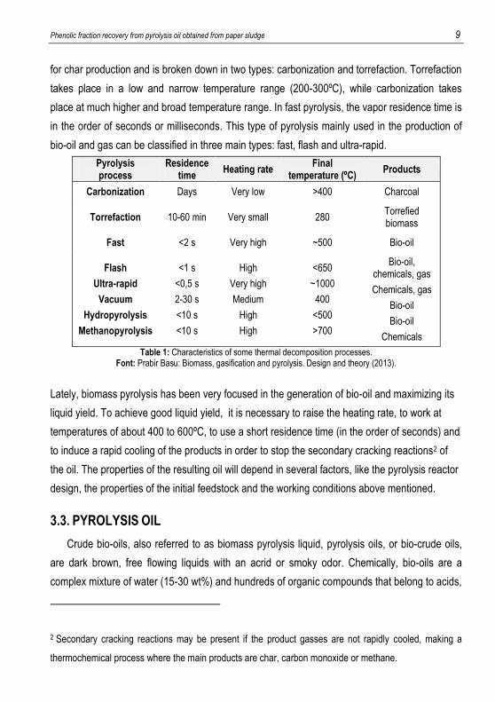
for char production and is broken down in two types: carbonization and torrefaction. Torrefaction
takes place in a low and narrow temperature range (200-300ºC), while carbonization takes
place at much higher and broad temperature range. In fast pyrolysis, the vapor residence time is
in the order of seconds or milliseconds. This type of pyrolysis mainly used in the production of
bio-oil and gas can be classified in three main types: fast, flash and ultra-rapid.
Pyrolysis process
Residence time
Heating rate Final
temperature (ºC) Products
Carbonization Days Very low >400 Charcoal
Torrefaction 10-60 min Very small 280 Torrefied biomass
Fast <2 s Very high ~500 Bio-oil
Flash
Ultra-rapid
Vacuum
Hydropyrolysis
Methanopyrolysis
<1 s
<0,5 s
2-30 s
<10 s
<10 s
High
Very high
Medium
High
High
<650
~1000
400
<500
>700
Bio-oil, chemicals, gas
Chemicals, gas
Bio-oil
Bio-oil
Chemicals
Table 1: Characteristics of some thermal decomposition processes. Font: Prabir Basu: Biomass, gasification and pyrolysis. Design and theory (2013).
Lately, biomass pyrolysis has been very focused in the generation of bio-oil and maximizing its
liquid yield. To achieve good liquid yield, it is necessary to raise the heating rate, to work at
temperatures of about 400 to 600ºC, to use a short residence time (in the order of seconds) and
to induce a rapid cooling of the products in order to stop the secondary cracking reactions2 of
the oil. The properties of the resulting oil will depend in several factors, like the pyrolysis reactor
design, the properties of the initial feedstock and the working conditions above mentioned.
3.3. PYROLYSIS OIL
Crude bio-oils, also referred to as biomass pyrolysis liquid, pyrolysis oils, or bio-crude oils,
are dark brown, free flowing liquids with an acrid or smoky odor. Chemically, bio-oils are a
complex mixture of water (15-30 wt%) and hundreds of organic compounds that belong to acids,
2 Secondary cracking reactions may be present if the product gasses are not rapidly cooled, making a
thermochemical process where the main products are char, carbon monoxide or methane.

10 González Rivas, Álvaro
Table 3: Chemical composition of fast pyrolysis liquid from wood.
Font: Michael J. McCall “Production of chemicals from pyrolysis”. US8158842 (2012)
(*) Phenol is included in the pyrolytic lignin
Table 2: Typical properties of pyrolysis oil from wood.
Font: Catalytic vapor cracking for improvement of Bio-oil. Hyun Ju Park et al. (2011)
aldehydes, ketones, alcohols, esters, anhydrosugars, furans, phenols, guaiacols, syringols, and
nitrogen compounds, as well as large molecular oligomers (holocellulose-derived
anhydrooligosaccharides and lignin-derived oligomers) (Balat et al. 2009).
The many different compounds in pyrolysis oil have their origin from the simultaneous
degradation of cellulose, hemicellulose and lignin during pyrolysis. The pyrolysis oil is generally
collected as one liquid, resulting in a very complex mixture of many different oxygenated
compounds with different functional groups. This makes identification and quantification of
compounds in pyrolysis oil a very difficult task (Garcia-Perez et al. 2007).
Typical physical properties (Table 2) and chemical composition (Table 3) of bio-oil obtained
during fast pyrolysis of wood are shown in the tables below:
The pyrolysis oil is neither a mixture of compounds at thermodynamic equilibrium nor a
stable product at room temperature. The viscosity tends to increase during storage, especially
3 Pyrolysis of lignin yields a range of products, being methoxy-substituted phenols the most
characteristic ones but also including simple phenols and oligomeric polyphenols.
Pyrolysis oil properties Value
Moisture content (wt%) 15-30
pH 2,5
Specific gravity 1,2
Elemental composition (wt%)
C 54-58
H 5,5-7
O 35-40
N 0-0,2
Ash 0-0,2
HHV (MJ/Kg) 16-19
Solids (wt%) 0,2-1
Major components Value (wt%)
Water 20-30
Pyrolytic lignin3 15-30
Aldehydes 10-20
Carboxylic acids 10-15
Carbohydrates 5-10
Phenols (*) 2-5
Furfurals 1-4
Alcohols 2-5
Ketones 1-5

Phenolic fraction recovery from pyrolysis oil obtained from paper sludge 11
BIO-OIL
Chemicals Resins Fertiliser Flavours Adhesive Acetic acid Industries feedstock
Fuels Hydrogen Upgrading (HDO) Fuel via syngas
Heat Co-firing of
boiler and furnace
Power Diesel engine Turbine
at higher temperatures, due to the reactions of certain reactive compounds thus forming larger
molecules. This is referred to as ageing (Oasmaa et al. 1999)
Because of all the properties mentioned above, bio-oilcan not be a substitute to traditional
petroleum based fuels or as sustainable feedstock for renewable liquids fuels. The main reason
being its lower heating value due to its high oxygen content. In addition, its high polarity makes
it immiscible with crude oil, making it unsuitable as co-feedstock in petroleum refineries.
Moreover, upgrading of bio-oil in current fossil oil refineries is rather difficult due to its high
tendency towards polymerization.
However, if we take bio-oil as a source of chemicals, where oxygen removal may not be
necessary, different technical and commercial applications may then become possible. Many
oxygen-containing chemical stocks are now produced from fossil fuels via oxidation or hydration
of olefins to introduce oxygen-containing functional groups. In contrast, these functional groups
are already present in bio-oil, but, although many chemical constituents in bio-oil are valuable,
their contents are still low, making their recovery technically difficult and costly.
3.4. DIFFERENT APLICATIONS OF BIO-OIL
When studying possible uses to pyrolysis oil, different approaches can be taken (Figure 1).
It can be seen as a possible feedstock for chemical products or as fuel for different uses.
Mainly, their applications have been found in the chemicals production and heat/power
generation rather than in the transportation sector.
Figure 1: Various applications of bio-oil. Font: Mohammad I. Jahirul et al. Biofuels production through biomass pyrolysis.

12 González Rivas, Álvaro
3.4.1. Energy valorization
Because bio-oils degrade with time, they cannot be used directly as a transportation fuel
without upgrading or blending (Oasmaa et al. 1999). However, another limitation is that fuels
derived from bio-oils have not been extensively investigated and the process of bio-oil
upgrading is under steady development worldwide for enhanced efficiency and improved fuel
properties. In addition, low cost processing technologies that could efficiently convert a large
fraction of the lignocellulosic biomass into liquid or gaseous fuels do not yet exist (Elkasabi et al.
2015).
Pyrolysis oil can be used without further treatment in furnaces and boilers in co-generation
plants as a source of energy. However, to cope with some of the properties and characteristics
of the oil, these installations need to be modified to cope with the use of bio-oil instead of fossil
fuels (Peters et al. 2015), (Ramirez et al. 2014). In a similar way, bio-oil can also be used as a
fuel in conventional diesel engines (Prakash et al. 2013) or gas turbines (Kallenberg, 2013),
which also need to be modified to cope with the properties of pyrolysis oil (varying chemical
composition and low pH).
3.4.2. Chemicals from pyrolysis oil
As mentioned before, the main attractive of thinking of bio-oil as a source of chemicals is the
enormous amount of value added chemical constituents that are present in it and the main
disadvantage is that these components are often in low content, which makes it difficult to
recover them. When facing this problem, the typical solution is to modify the pyrolysis working
conditions and/or do a series of pretreatments of the biomass to modify its properties so that the
resulting bio-oil has a higher yield of a specific chemical or group of chemicals and its further
treatment to obtain this value added product has a reduced cost of recovery. This procedure,
known as selective pyrolysis4, has been tested with promising results achieving bio-oil with a
high yield of components like furfural, hydroxyacetaldehyde or acetic acid amongst many
others.
4 Selective fast pyrolysis, differed from conventional fast pyrolysis which is usually aimed at the maximum bio-oil yield, is to drive the pyrolysis of biomass towards the products of interest, mostly by catalyst utilization, to maximize the yield of target product and obtain target products with high purity.

Phenolic fraction recovery from pyrolysis oil obtained from paper sludge 13
3.5. PAPER SLUDGE AS FEEDSTOCK FOR PYROLYSIS OIL
The topics described in this project will be developed within the frame of my scholarship at
Alucha Recycling Solutions S.L.
Alucha Recycling Solutions develops technological solutions that enable waste recycling.
Their focus is on used resources that are currently being landfilled or incinerated. Over the
years, they have been zooming in on streams that contain both organic and non-organic matter.
Examples are laminate materials (drink cartons, toothpaste tubes, pouches, etc.) and mixed
plastics, but also biomass streams such as sludges, rice husk and other similar streams. With
their technology, they are able to separate the organic from the inorganic matter, so recovering
useable resources, typically oil and metals or minerals.
This project focuses in the biomass paper sludge stream waste being generated at the
waste water treatment and deinking plants present in paper, tissue and board producing mills.
In the process of making paper, apart from the fibrous material and the chemicals that are
added in order to increase its properties and quality, a great amount of water and energy in form
of steam and electricity is needed. Consequently, nowadays paper producers face serious
environmental problems regarding the water content in their paper sludge (5-10m3/ton paper),
energy consumption (2-5 ton steam/ton paper) and atmospheric emissions. Paper sludge is
produced in paper, tissue and board recycling plants and it is a type of solid byproduct inherent
to their pulping and papermaking operations. Normally it contains a high amount of water and
fibers, but it is also rich in charges or minerals, which make paper sludge an important
feedstock for the recovery of valuable products. Because of the operational problems of further
treating paper sludge to recover paper, and the difficulty of separating the organic (fiber) and the
inorganic (minerals) fractions, paper sludge is currently treated as a waste stream and it is
commonly disposed in landfills (process that has some disposal costs attached) or co-
incinerated (cement kilns), causing environmental problems through chemical leaching and
greenhouse gas effect emissions production.
This project consists on pyrolyzing paper sludge for obtaining value added pyrolysis oil. This
technology has already been tested by Alucha Recycling Solutions at laboratory scale and
proven to be feasible, which led them to take the project to a further level and build a pilot plant
at the University of Twente in Enschede, The Netherlands. This pilot plant works at closer
conditions to fast pyrolysis than the multi-purpose laboratory scale reactor where these project

14 González Rivas, Álvaro
tests have been undertaken. The results obtained so far seem to be promising, as a semi-
commercial scale plant is now in development and will be commissioned by the end of 2016.
Until recently, the bio-oil was burnt in recovery boilers in order to obtain energy, this project
now aims to identify and to start developing a process which can turn bio-oil into a feedstock to
produce value-added chemicals.
Even though selective pyrolysis is a procedure that is giving promising results when it
comes to the obtainment of chemicals from pyrolysis oil, this project focuses on developing a
method to obtain fine chemicals from a bio-oil obtained from a defined feedstock (paper sludge)
and through a pyrolysis process (pyrolysis temperature, type of reactor, etc.) already defined.
3.6. CHEMICALS FROM PAPER SLUDGE PYROLYSIS OIL
Pyrolysis oil has a huge potential as feedstock for several chemical products and Alucha
Recycling Solution’s next objective is to investigate which of these chemical compound scan be
economically obtained through the simplest process possible. Having this in mind, the first step
was to take a look at the gas chromatography analysis5of different bio-oil samples that had
already been done in order to define its chemical composition.
The analysis where carried in a Mass spectroscopy thermo scientific LTQ 900, using an HP-
5MS column of 30m x 0,25 mm of internal diameter x 0,25 µm p. diameter. The process used
involved a temperature profile with a temperature of 35ºC passed the first minute and a slope of
4ºC/min with a temperature of 320ºC after 20 minutes of analysis.
The results of the GC:MS performed are shown in the graph below (Figure 2 & Table 4),
where we can see pyrolysis oil samples of three different companies: Companies #1, #2 and #3.
5 Gas chromatography is a chemical analysis which separates and identifies chemicals from a complex sample. A gas chromatograph uses a flow-through narrow tube known as the column, through which different chemical constituents of a sample pass in a gas steam (carrier gas) at different rates depending on the various chemical and physical properties and their interaction with a specific column filing, called stationary phase. As chemicals exit the end of the column, they are detected and identified electronically. The function of the stationary phase in the column is to separate different components, causing each one to exit the column at different time (retention time).

Phenolic fraction recovery from pyrolysis oil obtained from paper sludge 15
The three pyrolysis oils where produced under the
same conditions at the laboratory scale multi-purpose
pyrolysis reactor. This reactor did not operate at proper fast
pyrolysis conditions, since the feedstockwas introduced in
the reactor at the beginning of the experiment, and not
when the temperature inside of the reactor is close to the
pyrolysis temperature. Moreover, the residence time of
gases is of the order of seconds. The methodology of
these experiments will be further explained in the Section-
6 of this report.
When we compare the chemical composition of the pyrolysis oil obtained from the samples
from these companies with the bio-oil obtained from a wood-based feedstock (Table 3) we can
appreciate how the composition of bio-oil changes significantly depending on the initial
feedstock. The first observation we can do when looking at the results, is the lower amount of
ethers, esters and hydrocarbons present in all three samples, and that the yield of hydrocarbons
is almost inexistent due to the high amount of oxygen. When we remove from the picture the
peaks corresponding to components which cannot be identified and the ones that belong to
components too complex to be classified in of the categories listed, we are left with five big
Functional group wt%
Water 20-30
Alcohols 6-9
Carboxylic acids 16-25
Phenolic fraction 11-14
Aldehydes 3-4
Ketones 24-36
0
5
10
15
20
25
30
35
40
ALCOHOLS
CARBOXYLICACIDS
PHENOLICFRACTION
ALDEHYDES
KETONES
ETHERSESTERS
HYDROCARBONS
UNCLASSIFIED
UNKNOWN
Figure 2: Composition of pyrolysis oil three different paper sludge providers.
Font:Author
Table 4: Chemical composition of samples from three diferent companies. Font: Author

16 González Rivas, Álvaro
groups of chemicals whose presence is significant in bio-oil: alcohols, carboxylic acids, phenol
and aromatic derivates, aldehydes and ketones.
Focusing on these five groups separately, it is possible to appreciate that the amount of
alcohols obtained from the three oils is very similar and the difference of aldehydes and
phenolic fraction is very small between the three samples. When it comes to acids and ketones,
the situation is slightly different: the three samples yielded quite similar amounts of these groups
of components, but the difference between experiments is bigger than compared with the other
groups.
With three analyses we can have a general overview of the chemical composition of
pyrolysis oil from paper sludge. Nevertheless, we have to take into consideration that a slight
change in the pyrolysis conditions or the pretreatment of the biomass can change the yield of
every functional group significantly, and more analysis would be advisable when the pyrolysis oil
starts to be produced at the pilot plant instead than at the laboratory scale reactor.
Phenolic fraction recovery from pyrolysis oil obtained from paper sludge 17
4. OBJECTIVES
1. Investigating the current state of the art of the upgrading of bio-oil to its use as a
sources of chemicals
2. Select the most promising methods that are already being used and try to obtain
similar results using paper sludge as feedstock.
3. Determine the feasibility of said methods for its industrial application.
4. Depending on the results obtained from testing the different technologies,
investigate and plan the next steps required to further investigate the process.

18 González Rivas, Álvaro
5. CHEMICALS FROM PYROLYSIS OIL
5.1. STATE OF THE ART
The first step of every project is to do a literature review. In our case, the obtainment of
chemicals from pyrolytic oil is still a very recent research topic. That being said, a lot of
improvement has been done in the last years and some processes are starting to prove to have
some potential when it comes to its industrial application.
The next pages are a review of some of the processes that have shown promising results
when it comes to obtaining chemicals through a feasible process and that are starting to be
scaled industrially.
5.1.1. Acetic acid obtainment
Acetic acid is a high volume chemical utilized as a reactant, solvent, or catalyst in numerous
processes. For example, acetic acid is converted according to known reaction pathways to vinyl
acetate monomer, which is polymerized to form latex emulsion resins for paints and adhesives.
Fibers and plastics as well are manufactured from acetic anhydride, which is another conversion
product of acetic acid (Kocal, 2014).
Recently, methods for producing acetic acid from renewable carbon sources, in a manner
that is generally less expensive than conventional routes based on fossil-derived carbon
sources, have been investigated. These methods address the separation and recovery of acetic
acid as a substantial product of biomass pyrolysis.
Amongst the enormous amount of chemicals that compose bio-oil, acetic and formic acid,
and other organic acid components are present. Since these organic acids are responsible for
corrosion of metals and storage instability of pyrolysis oil, removal of these components can be
a useful approach both to isolate them and use them as feedstock for other processes or to
reduce the corrosiveness of the pyrolysis oil in case we want to improve its properties for
another use.
Removal of acetic and formic acid has been investigated by various authors. The water-
soluble fraction of bio-oil contains various organic acids, aldehydes and simple phenolic
components. A further distillation of this fraction was reported to give a distillate containing
formic and acetic acid as well as some other volatile components, and treating this distillate with

Phenolic fraction recovery from pyrolysis oil obtained from paper sludge 19
calcium oxide led to form calcium salts of organic acids that could be treated with a strong
inorganic acid to recover the acids (Sukhbaatar et al. 2009). However, the precipitates also
included high amounts of pyrolytic lignin and the distillation process proved to be costly.
Development of lower cost separation methods would be desirable. Removal of acetic acid from
bio-oil has also been investigated using an anion-exchange resin. These approach proved to be
very effective when it comes to remove the organic acids of the oil, but the yields of recovered
bio-oil where low (Sukhbaatar et al. 2009) due to adsorption of bio-oil components on resin
particles and some improvement on this technology is needed for this purpose.
5.1.2. Hydrogen production
Hydrogen is considered to be a clean fuel and could have an important role in reducing
environmental emissions in the future. Unlike fossil fuels, hydrogen burns cleanly, without
emitting any environmental pollutants. In addition, hydrogen also possesses the highest energy
content per unit of weight (about 120.7 MJ/kg) (Ye, T. et al. 2009). Hydrogen is also an
important raw material for the chemical industry, which is mainly used for ammonia production
or refining and methanol production. Currently, commercial hydrogen is primarily produced from
methane and other hydrocarbon feedstocks, such as naphtha and heavy residues from
petrochemical process, among others (Ye, T. et al. 2009). An alternative method of producing a
H2 rich gas is the catalytic steam reforming of the aqueous fraction of bio-oils. This method
requires an initial separation of the bio-oil in two phases: the water-soluble fraction, containing
the low molecular weight organics, and the insoluble fraction, enriched with lignin-derived
compounds. The aqueous phase, being a complex mixture of different compounds such as
acids, ketones, aldehydes, alcohols, sugars, phenols and more complex carbohydrates in water,
can be catalytically reformed to produce a gas with a high H2 content.
Probably, production of hydrogen from bio-oil reforming is one of the most promising options
because it can achieve high hydrogen yield and high content of hydrogen. The main difficulty of
this method relays on the use of a catalyst. The efficiency of the process is determined by the
ability of the catalyst to catalyze the steam reforming reactions of the oxygenated organic
compounds in bio-oil and the water-shift reaction.
Conventional steam reforming catalysts are 10-33 wt%NiO on a mineral support (alumina,
magnesia, etc.), usually operating at T=600-700ºC. Recent investigation showed that Ni-Cu
bimetallic catalyst supported on SiO2, Al2O3, ZnO/Al2O3exhibited acceptable activity, stability and

20 González Rivas, Álvaro
selectivity to hydrogen. In these systems, Cu is the active agent and promotes fast ethanol
dehydrogenation to acetaldehyde, Ni promotes C-C bond rupture of acetaldehyde to produce
CH4 and CO and increases hydrogen selectivity (Ye, T. et al. 2009). Noble and precious metals
(Pt, Ru, Rh) are generally more effective than the Ni-based catalyst and present less carbon
depositing but are not very common because of their high cost. Another hindering is the
deactivation of catalyst due to coke or oligomer deposition. Thus, it is very important to
significantly reduce the carbon depositions during the bio-oil reforming process and lower the
reforming temperature before this method can be applied at industrial scale (Sanna et al. 2005).
5.1.3. Bio-ethanol production
The main objective of this method is to convert the anhydrosugars in pyrolysis oils into
ethanol. Pyrolytic sugars 6 are extracted from the bio-oil via phase separation and acid-
hydrolyzed into glucose, which will be fermented into ethanol. Despite being a process to obtain
chemicals (glucose that will be converted in ethanol), the final purpose of these processes is the
obtainment of transportation fuels that can be a substitute for the traditional fossil fuels. When
treating biomass under fast pyrolysis conditions, one of the primary degradation products of
cellulose is levoglucosan (1,6-anhydro-b-D-glucopyranose) (Bennett et al. 2009). As an
anhydrosugars, levoglucosan can be hydrolyzed to glucose, thereby providing a potentially
rapid and efficient route to the production of bio-ethanol.
The initial step of this method is to separate bio-oil into aqueous and non-aqueous phase so
the majority of anhydrosugars are in a different phase than the phenolic components. Once the
separation is completed, these sugars are hydrolyzed into glucose using sulfuric acid as a
catalyst. Sulfuric and carboxylic acids are then neutralized with Ba(OH)2and the phase rich in
sugars is further detoxified with activated carbon. The resulting aqueous phase rich in glucose is
fermented to produce ethanol. Different yeasts have been tested (specially S. cerevisiae)
(Luque, L. et al. 2014), (Lian, J. et al. 2010) giving promising results, but the main difficulties of
these method relays on the initial phase separation and the subsequent removal of toxic
compounds, like phenols or acids, that could inhibit the growth of the yeast. Therefore, proper
phase separation needs to be developed before this process is industrially feasible.
6Pyrolytic sugars: name given to the mixture of sugars, aldehydes and ketones present in the pyrolysis oil.

Phenolic fraction recovery from pyrolysis oil obtained from paper sludge 21
5.1.4. Phenolic components
Because bio-oil contains lots of simple phenols and oligomeric polyphenols (or pyrolytic
lignin), the application of bio-oil depends on which fraction is used. A very useful application way
for phenolic compounds in bio-oil is to recover simple phenols from bio-oil, because they are
valuable chemicals which are suitable for a broad range of applications. Despite that, due to the
difficulty in separating simple phenols and the low yield of this component in bio-oil, this method
has not been further investigated. In contrast, efforts have been made to apply pyrolytic lignin as
a substitute for fossil phenols in phenolic resins. Phenolic resins are normally synthesized by
acid or basic catalyzed reactions between phenols and aldehydes. Phenol-formaldedhyde (PF)
resin, a representative phenolic resin, is obtained by the reaction of phenol or substituted phenol
with formaldehyde, leading to the formation of novolacs (thermoplastic) or resoles
(thermosetting), respectively. Phenolic resins are widely used in many industries, including
electronic laminating and wood composite industries (Kim, J. S. 2015).
Several processes for the recovery of the phenolic fraction from pyrolysis oil from biomass
have been investigated, using different procedures and methods having all in common that the
ultimate product is a phenolic fraction, which is desired to be as pure as possible.
Although bio-oils containing a high content of phenolic compounds have a strong potential
for the replacement of fossil phenol, they suffer from a relatively low reactivity in the phenolic
resin synthesis, as typical bio-oil contains a low concentration of reactive phenol, and the
mixture of phenolic compounds (primarily alkylated phenol and aromatic ethers) in bio-oils is
less reactive than pure phenol. In addition to this, all processes for recovering the phenolic
fraction involve an initial separation of the aqueous and non-aqueous phase that still hinder the
feasibility of the process and its industrialization.
5.2. PHASE SEPARATION
Taking a closer look to all the processes stated above, it is possible to appreciate that they
all have in common the need of an initial treatment to separate bio-oil in two phases (aqueous
and non-aqueous) in order to simplify the complex mixture of components that bio-oil is made of
and in an attempt to obtain two phases with similar chemical and physical properties. Although
this initial separation may not seem complicated to perform is one of the main factors that
hinders the obtainment of chemical products from pyrolysis oil.

22 González Rivas, Álvaro
Conventional separation technologies such as solvent extraction, column chromatography
and distillation are amongst the most investigated.
5.2.1. Solvent extraction
Solvent extraction is a process which selectively dissolves target components of a mixture
of components into a solvent for which those components have a greater affinity. Commonly
used solvents for the extraction of specific compounds from bio-oil include water, alcohols, ethyl
acetate, hydrocarbons such as toluene and n-hexane, ethers, ketones, dichloromethane, and
alkaline solutions (Vecino Mantilla, S. et al. 2015).In solvent extraction procedures, large
volumes of solvents are required, making the industrialization of some extractions unfeasible.
5.2.2. Column chromatography
The separation of bio-oil components through column chromatography commonly utilizes
silica gel and aluminum oxide as the stationary phase, where the mobile phase is selected
according to the polarity of bio-oil components which are to be extracted. The separation is
based on the different adsorption capabilities of bio-oil components onto the stationary phase.
Column chromatography can economically separate bio-oil, but its low throughput makes it only
suitable for high value-added compounds (Zeng, F. et al. 1987).
5.2.3. Distillation
Distillation separates bio-oil components according to their different volatilities. Atmospheric
pressure-, vacuum-, steam-, and molecular distillation can be applied to bio-oil separation.
Boiling of bio-oil starts below 100ºC at atmospheric pressure, and stopping the distillation at
280ºC leaves 35–50 wt% of the starting material as a residue (Czernik et al. 2004). In contrast
to atmospheric pressure distillation, vacuum distillation has a strong advantage, allowing to
operate at much lower temperatures. The distilled organic fraction from vacuum distillation
contains almost no water and fewer oxygenated compounds, although the method uses large
amounts of energy. Steam distillation, which requires a relatively large initial capital investment,
can be applied for the separation of bio-oil components, introducing steam into the distilling
column to heat bio-oil and decrease its viscosity. With the addition of steam, the organic-water
mixture (bio-oil) boils at a lower temperature (below 100ºC) (Czernik et al. 2004), allowing
thermally sensitive compounds to be separated with reduced decomposition. Molecular

Phenolic fraction recovery from pyrolysis oil obtained from paper sludge 23
distillation, which is widely applied in petrochemical, fine chemical, medicine, pharmaceutical,
and food-processing industries, is also considered to be an appropriate process for the
separation of thermally unstable bio-oils. Compared to other forms of distillation, molecular
distillation has the advantages of lower operating temperatures, shorter heating time, higher
separation efficiencies and minimal losses by thermal decomposition. In a study of the
separation of bio-oil using molecular distillation, a maximum distillate yield of 85% was obtained
without coking or polymerization (Wang, S. et al. 2009). The main disadvantage of molecular
distillation lies in the high equipment costs.
5.3. SELECTION OF THE TARGET CHEMICALS TO BE RECOVERED
All the methods to obtain chemicals described above have in common an initial separation
of the bio-oil in two phases: the aqueous phase, containing all the sugars, and the non-aqueous
phase, composed by the pyrolytic lignin, even though some of the methods focus on obtaining
chemicals from the aqueous phase and some from the organic phase.
The table below shows a comparison of the possible methods mentioned, with its benefits
and withdraws, in order to serve as guide to decide which process is more interesting to be
investigated.
From all the methods previously mentioned, the obtainment of the phenolic fraction from
pyrolysis oil to use it as a substitute of phenol obtained from fossil resources will be studied.
One of the main factors that influenced into taking this decision was the fact that after obtaining
the phenolic fraction it is possible to stop the process right after the phase separation and use
the obtained organic fraction as a partial substitute of phenol, unlike the other three processes
mentioned, which need further treatment to obtain a final product that can be commercialized.
Other important factors are the non-restrictive working conditions that this process needs to be
carried out, or the possibility of developing a method which can obtain substitutes of phenol
from a greener and cheaper process.
The table below (Table 5) shows a comparison of the possible methods mentioned, with its
benefits and withdraws, in order to serve as guide to decide which process is more interesting to
be investigated.

24 González Rivas, Álvaro
OBJECTIVE DESCRIPTION METHOD PROS CONS PHASE
SEPARATION
ORGANIC ACID
OBTENTION
· Acids like acetic acid are used in numerous processes. · Alternative obtention of acids from the traditional fossil-derived carbon source. · Acetic and formic acid are known to be amongst the compounds with higher yield in bio-oil. · The removal of organic acids can improve the properties of oil for its use as fuel.
Distillation of the water soluble fraction of pyrolysis oil, followed by treating the distillate with CaO to form calcium salts from which, upon treating with a H2SO4, the acids are recovered.
· Simple method with no restrictive conditions. · The chemicals needed are do not hinder the feasibility of the process with its price or the amount needed.
· The precipitates include high amounts of pyrolytic lignin · Distillation cost prohibitive.
YES
Anion-exchange resin.
· Very effective way to remove the organic acid from oil. · Effective way to improve the quality of oil removing certain components.
· Yield of recovered oil is low due to adsorption of bio-oil components on resin particles.
YES
HYDROGEN PRODUCTION
· Hydrogen has a huge potential as fuel. · Important raw material for the chemical industry · Alternative obtention of hydrogen from the traditional production from hydrocarbon feedstocks.
Catalytic steam reforming of the aqueous fraction of bio-oil.
· High content of gas with high yield of hydrogen. · Can be carried in two steps with less restrictive operation conditions.
· Process efficiency determined by catalyst. · Price and deactivation of catalyst.
YES
BIO-ETHANOL PRODUCTION
· Convert sugars in pyrolysis oil into ethanol. · Alternative obtention of ethanol that can be used as transportation fuel.
Hydrolysis of anhydrosugars of bio-oil into glucose using sulfuric acid as catalyst followed by fermentation.
· Rapid and efficient route to produce bio-ethanol. · Price and amount of chemicals needed and operation
· Sulfuric and carboxylic acid need to be neutralized. · Phase rich in sugars needs to be detoxified before fermentation.
YES

Phenolic fraction recovery from pyrolysis oil obtained from paper sludge 25
conditions are not restrictive. · Several yeasts are able to ferment glucose into ethanol and the price and working conditions are not restrictive.
· Process conditions need to be strictly controlled to meet the needs of the microorganisms.
OBTENTION OF THE
PHENOLIC COMPONENTS
· Phenols are valuable chemicals with a broad range of applications.
Separating simple phenol present in bio-oil.
· Route to obtain phenol from a greener feedstock rather than the traditional method from fossil sources.
· Several steps needed to separate simple phenols. · Low yield of simple phenols in oil.
YES
· Pyrolytic lignin can be a substitute for fossil phenols in phenolic resins. · Phenolic resins are widely used in the industry
Recovering pyrolytic lignin from bio-oil by liquid-liquid extraction
· After separating the oil in two phases little additional treatment is needed. · Resultant phenolic fraction can be used as a cheaper source of phenol in existent processes. · Operating conditions are not restrictive
· Low amount of reactive phenol. · Mixture of phenolic components is less reactive and include non-phenolic compounds.
YES
5.4. RECOVERY OF THE PHENOLIC FRACTION
As stated before, different methods for conducting the separation of bio-oil in two phases
have been investigated. Most of them present important drawbacks that hinder its
industrialization, but some also proved to be great alternatives although they require further
investigation to cope with some difficulties. From the methods mentioned in the previous pages,
Table 5: Benefits and withdraws of the selected methods to obtain chemicals from bio-oil from paper sludge.
Font: Author

26 González Rivas, Álvaro
solvent extraction is considered to be a potential method to carry this initial separation
successfully and that is why some experiments will be carried on to test some of the latest
methods that have given promising results.
After carrying out some more literature review about solvent extraction, two methods where
found that successfully overcame one of the main problems of solvent extraction: the high
amounts of solvent needed. These methods where tested using lignin rich biomass, obtaining
promising results, and further experiments will be made to see if these technologies can give
similar results when applied to a bio-oil obtained from paper sludge.
5.4.1. L-L extraction using methanol and water
This process is based on the work carried out by Sukhbaatar, B. et al. (2009), where they
investigated the application of lignin separated from bio-oil in oriented strand board (OSB)
binder phenol-formaldehyde resins. As stated before, it is almost indispensable to carry out the
separation of bio-oil in two phases, and they came out with an alternative solvent extraction
which reduced the amount of solvent needed, improving significantly the economy of the
process in comparison with previous methods.
The separation of lignin has been investigated based on the lignin’s good solubility in
organic solvents and poor solubility in water (Chum, H. L. et al. 1992). An initial attempt of
mixing the bio-oil with ethyl acetate and washing the resultant organic layer with water and
sodium bicarbonate yielded up to 31% of pyrolytic lignin (Chum, H. L. et al. 1993). However, a
commercialization effort of the technology was initiated but not continued due to the costly lignin
separation procedure and variable yields of lignin due to the water and sodium bicarbonate
washing procedures (Sukhbaatar, B. et al. 2009).
In their work, Sukhabaatar, B. et al. separated the lignin fraction from a woody feedstock
bio-oil using only water and methanol with a 25 wt% of bio-oil. Despite the yield being lower
than the previous method, the amount of solvent needed is much lower and the amount of steps
required to conduct the separation is lower, which benefits the economy of the process. In their
experiments, they did an initial test using only water and bio-oil was mixed with water in a 1:1
ratio. Despite they obtained two clearly separated phases, the phenolic fraction was found to
contain certain non-lignin materials that made it unsuitable for its use as a phenol replacement.
Therefore, this fraction was further treated with methanol in a 1:1 ratio and then the lignin

Phenolic fraction recovery from pyrolysis oil obtained from paper sludge 27
fraction was precipitated adding about the same amount of water. After allowed to stand at room
temperature and evaporating the remaining methanol pyrolytic lignin was obtained with a yield
of 22 wt%, which means that 71% of the phenolic fraction present in the initial bio-oil was
recovered.
5.4.2. Method of separating lignin derived compounds from pyrolysis oil
An alternative method to the most studied extraction with a polar hydrophilic solvent,
capable of separating light oxygenates from lignin derived compounds was carried out by Wang
et al. (2014)
It has been found that the separation of lignin derived compounds from bio oil by use of
reversible α-hydroxysulfonic acid remarkably increase the extraction efficiency. Hydroxyl
aldehydes and ketones present in bio oil are combined with SO2 and water to generate α-
hydroxysulfonic acid in situ. The presence of α-hydroxysulfonic acids in bio oil eliminates the
surfactant properties of bio –oil, makes the water very acidic (pH<1), and drives the lignin and
phenolic based species into a separate phase. Once the water is separated, the carbonyls can
be regenerated by heating the mixture or reducing the pressure, allowing volatile SO2 to depart
the reaction zone.
The acid is generally formed by reacting at least one carbonyl compound with sulfur dioxide
and water. This reaction is a true equilibrium, with in a facile reversibility of the acid. That is,
when heated, the equilibrium shifts towards the starting carbonyl, sulfur dioxide, and water. If
the volatile components are allowed to depart the reaction mixture via vaporization or other
methods, the acid reaction completely reverses and the solution becomes effectively neutral.
These process not only reported good results in separating bio-oil in two phases, but also
grants the possibility of using both phases to obtain chemicals (phenols from the apolar phase
and glucose from the polar phase).
5.5. ANALYSIS TO DETERMINE THE AMOUNT OF PHENOLIC FRACTION
PRESENT IN BIO-OIL
In order to determine the efficiency of each of the methods, an analysis technique that
shows the amount of phenolic fraction in the samples needs to be selected. This analysis will be
done to the initial bio-oil obtained after the pyrolysis test and to the sample recovered after

28 González Rivas, Álvaro
treating it to separate it in two phases. This analysis should give a clear and representative
value, which would allow to compare the percentage of phenolic fraction in the initial and the
final product.
Due to the high amount of different components present in bio-oil, an analysis which
identifies the entire chemical composition of pyrolytic oil is still not available, but different
methodologies for where investigated, each of them with benefits and disadvantages when
applied to bio-oil samples.
With all the considerations mentioned below (Table 6), GC:MS was considered to be the
most suitable technique for this experiments, since not only identifies a board range of
components (which will be useful to identify components which were not initially taken into
consideration but that represent an important percentage of the pyrolysis oil), but also is the
technique which suffers less interferences caused by the high number of components present in
bio-oil. For each chromatography, the methodology will be identical to the one followed with the
three initial samples of bio-oil analyzed: all the components identified will be classified into
functional groups, allowing a quick comparison between samples.
Analysis Description Advantages Disadvantages
PHENOL NUMBER
Colorimetric analysis which determines the quantity of phenolic components in a
sample by using free phenol as referent. The sample needs to
be previously distilled for removing all the non- phenolic
components that may give color to the pyrolytic oil.
Once the sample is distilled the interference
produced in the result by non-
phenolic components is
reduced. Obtainment of a
single value which is indicative of the
presence of phenolic
components in the sample.
Difficult to know the efficiency of the distillation due to the high amount of components. It is possible
that some phenolic components are distilled as well. These factors
make it easy to obtain a result which is not
accurate

Phenolic fraction recovery from pyrolysis oil obtained from paper sludge 29
GC:MS (Gas chromato-
graphy mass
spectrum)
The sample is introduced in the chromatography column, which
has a defined temperature slope. Each component leaves
the column at a certain time (retention time) which is
distinctive for each compound. Depending on the properties of
the column, the components move at a velocity determined
by its polarity
Allows to obtain a graphic in which
each peak represents an
identified component. A huge
range of components can be identified with this
method.
Because of the high amount of components, some of the peaks are mixtures of two or more
chemicals. Certain components (like water or some alcohols) cannot be
identified in the same column as phenolic
components. Chemicals which have small yield in
the sample are not identified.
HPLC (high performanc
e liquid chromatogr
aphy)
The sample is introduced in the column and its components are
differentially delayed depending on the interactions
which they suffer with the column. It works under the same principle as GC:MS
Obtains a graphic in which each peak is
a chemical component (or
mixture of similar chemicals). A huge
range of components can be
identified in the same column.
The obtained peaks are difficult to identify without a proper pattern. Due to the complex composition of
bio-oil, several components are not identified and certain
compounds can cause interferences.
NMR (Nuclear magnetic
resonance)
Spectroscopic technique based on the interaction between
atoms under the influence of a magnetic field and an
electromagnetic field of a specific frequency used to
obtain information about the properties of the chemical compounds present in the
sample
Technique capable of identifying precisely the
components of a sample by
determining the atoms of each
compound.
A high amount of chemicals present in the
sample cause interferences in the
identification of each component. Aromatic
compounds without phenol might be identified as
phenolic fraction as well and acid components are
also difficult to differentiate
Table 6: Benefits and withdraws of different analysis used to determine the amount of phenolic fraction in bio-oil.
Font: Author

30 González Rivas, Álvaro
6. BIO-OIL UPGRADING FOR RECOVERING THE
PHENOLIC FRACTION
The main objective of this project is to prove the feasibility of the methods explained before
for recovering the phenolic fraction of bio-oil. In this section of the report, the process used to
obtain pyrolysis oil from new samples from the same companies mentioned before and the
treatment done to this oil to isolate the phenolic fraction are explained.
6.1. FEEDSTOCK
As stated before, paper sludge obtained at paper mills is a solid byproduct of pulping and
papermaking operations which contains a high amount of water and fiber as well as minerals.
Because of its composition, paper sludge needs to be treated before being used as feedstock
for pyrolysis oil (Figure 3). This pretreatment generally consists on a drying step to remove the
high amount of water present in the sample, and a shredding process to reduce the size of the
sample and increase the contact surface of the particles.
Figure 3: Paper sludge samples before and after drying and shredding the feedstock.
Font: Author.
F
Phenolic fraction recovery from pyrolysis oil obtained from paper sludge 31
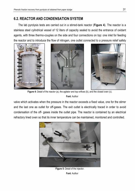
6.2. REACTOR AND CONDENSATION SYSTEM
The lab pyrolysis tests are carried out in a stirred-tank reactor (Figure 4). The reactor is a
stainless steel cylindrical vessel of 12 liters of capacity sealed to avoid the entrance of oxidant
agents, with three thermo-couples on the side and four connections on top: one inlet for feeding
the reactor and to introduce the flow of nitrogen, one outlet connected to a pressure relief safety
valve which activates when the pressure in the reactor exceeds a fixed value, one for the stirrer
and the last one as outlet for off-gases. The exit outlet is electrically traced in order to avoid
condensation of the off- gases inside the outlet pipe. The reactor is contained by an electrical
refractory lined oven so that its inner temperature can be maintained, monitored and controlled.
Figure 4: Detail of the reactor (a), the agitator and top orifices (b), and the closed oven (c).
Font: Author
F
Figure 5: Detail of the injector.
Font: Author
F

32 González Rivas, Álvaro
The reactor’s material feed inlet consists of a screw injector (Figure 5) used to dose the
sample in when the reactor has reached the desired pyrolysis temperature. Using the injector to
feed the sample we reduce the residence time of gases (avoiding cracking reactions of vapors
at high temperatures) and increase the heating velocity.
The condensation system (Figure 6) consists of two double tube condensers(one of 600
mm and one of 300 mL) connected in series, followed by a third condenser which consists of a
cotton filled tube. The two double tube condensers have a vessel connected at the bottom in
which the oil is collected. All the components are glass made and need to be manipulated with
caution. When assembling, in order to keep the system gas tight, grease is applied at the joints.
6.3. EXPERIMENTAL PROCEDURE
The experiences are divided in two main parts: the pyrolysis tests, from which we will obtain
the pyrolytic oil, and the phenolic fraction recovery, where the oil is treated to isolate this fraction
conducting one of the methods described previously.
6.3.1. Pyrolysis test
The steps followed during the described experiences are listed below.
Reactor and the condensation system assembly
1. The stirrer is coupled in the reactor taking special attention to its mechanical
alignment.
Figure 6: Detail of the condensation system.
Font: Author
F
Phenolic fraction recovery from pyrolysis oil obtained from paper sludge 33
2. The body and the top of the reactor are joint by 12 screws previously coated with
copper grease.
3. The injector is mounted on the reactor inlet and a connection is attached to the top
of the injector to introduce the nitrogen. The nitrogen tube is connected to a
rotameter in order to adjust its flow. Before sealing the adapter, the feedstock is
placed in the injector’s hopper.
4. The reactor is introduced in the oven and the axle of the stirrer is coupled to an
electrical motor.
5. The reactor outlet consists of a flexible electrically traced pipe, which is connected
to the condenser system described above. At the end of this flexible pipe there is
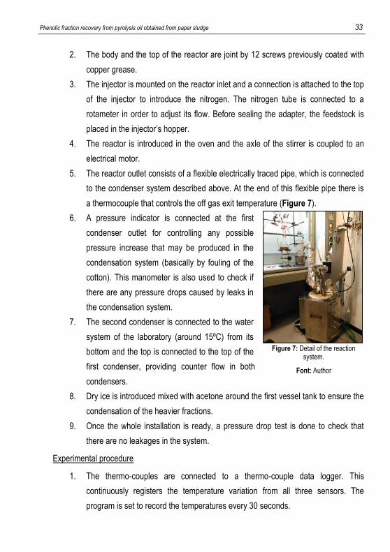
a thermocouple that controls the off gas exit temperature (Figure 7).
6. A pressure indicator is connected at the first
condenser outlet for controlling any possible
pressure increase that may be produced in the
condensation system (basically by fouling of the
cotton). This manometer is also used to check if
there are any pressure drops caused by leaks in
the condensation system.
7. The second condenser is connected to the water
system of the laboratory (around 15ºC) from its
bottom and the top is connected to the top of the
first condenser, providing counter flow in both
condensers.
8. Dry ice is introduced mixed with acetone around the first vessel tank to ensure the
condensation of the heavier fractions.
9. Once the whole installation is ready, a pressure drop test is done to check that
there are no leakages in the system.
Experimental procedure
1. The thermo-couples are connected to a thermo-couple data logger. This
continuously registers the temperature variation from all three sensors. The
program is set to record the temperatures every 30 seconds.
Figure 7: Detail of the reaction system.
Font: Author

34 González Rivas, Álvaro
Note: The middle temperature transmitter gives the process value temperature to
the oven temperature loop controller.
2. The electrical tracing is switched on, the water which feeds the condenser is
connected and a nitrogen flow of 5 L/min is introduced to purge out the oxygen
from the system.
3. The oven temperatures are increased (Set points 1 and 2) to the desired values
and the temperature profiles are registered.
4. Once the temperature of the bottom of the reactor reaches the desired value (the
pyrolysis temperature) the sample is injected. Depending on the amount of
sample is advisable to introduce it in separate batches to avoid a drastic increase
in the exit temperature of the reactor, which would hinder the proper condensation
of the gasses.
5. Once the pyrolysis has ended, the oven, the stirrer and the water flow of the
condensers are switched off.
Cleaning and sample collection
1. Once the reactor and the oven temperatures have decreased, the condensation
system is disassembled inside the fume hood.
2. The liquid oil in the vessels is collected and every component of the condensation
system is weighed before and after cleaning it with acetone.
3. The injector and the top cover of the reactor are removed and the stirrer is
uncoupled from the motor.
4. The solids remaining in the reactor are collected and weighed.
5. A mass balance is conducted knowing the amount of solids and liquid collected
and the initial quantity of sample to calculate the amount of gas generated.
6. Different types of analysis are done, depending on the objectives of the test. In
our case, only gas chromatography of the liquid was performed.
Calculation of the amount of minerals
1. Approximately 5g of the solids collected from the reactor are placed on a ceramic
plate and introduced in the oven, which is not completely closed and has an
oxygen entrance.

Phenolic fraction recovery from pyrolysis oil obtained from paper sludge 35
2. The solids are left in the oven at a temperature of 450ºC (to avoid degradation of
the minerals) for six hours. The sample is weighted every two hours in order to
know when a complete oxidation has been achieved. The difference is the fraction
of inorganic products.
Once the pyrolysis test has been completed, the oil obtained is further treated to recover the
phenolic fraction. The methods previously explained where tested following the next steps.
6.3.2. Solvent extraction
The main idea of this procedure is to dilute the aqueous fraction further more by adding
water and then decanting the mixture, obtaining the organic fraction (which is heavier) and
decant it one last time after adding methanol for enhancing even more the separation of the
polar and the apolar components (Figure 8).
1. The bio-oil obtained in the pyrolysis test is collected from the vessel tanks and
placed in a 500ml capacity glass decanter.
2. Water is added in a 1 to 1 ratio to bio-oil and left at room temperature for 2h.
3. The water insoluble fraction is decanted giving a viscous and black product.
4. This organic fraction is further treated with methanol, also in a 1 to 1 ratio of bio-oil
and methanol.
5. The lignin fraction is precipitated adding water incrementally while stirring until no
further precipitation is observed.
Figure 8: Detail of different parts of the solvent extraction method.
Font: Author
F

36 González Rivas, Álvaro
6. The mixture is then heated to evaporate the methanol and the remaining water
and the dark viscous lignin material that is left in the bottom.
7. The collectable solids are sent for analysis
6.3.3. Sulfur extraction
The idea of this method is to substitute the traditional polar hydrophilic solvent used in
solvent extraction. The bio-oil obtained during the pyrolysis experiment is collected and placed
in a Kitasato flask (Figure 9).
1. Water is added in a 3:1 bio-oil to water ratio.
2. While stirring the mixture, sulfur dioxide is introduced in stoichiometric excess and
allowed to react for one hour.
Note: Sulfur dioxide is generated in situ by combusting sulfur in the presence of
oxygen.
3. Once the reaction has taken place, the mixture is heated in order to reverse the
equilibrium. The sulfur dioxide gasses are removed by introducing a reverse nitrogen
flow.
4. The mixture is cooled down to room temperature by introducing a cooling air stream
while the mixture is left to settle down for another hour.
5. The aqueous fraction is removed by decantation and the solids are collected and sent
for analysis.
Figure 9: Detail of different parts of the sulfur extraction method.
Font: Author
F

Phenolic fraction recovery from pyrolysis oil obtained from paper sludge 37
6.4. RESULTS AND ANALYSIS
Two initial pyrolysis experiments where planned with the objective of obtaining enough oil to
test the two methods described above. For each experiment we will use a different feedstock
and the oil obtained will be analyzed via GC:MS before and after the extractions. Without taking
into account the three weeks that the analyses take to be done, each experiment lasts for
approximately three days, breaking down this time in the following operations:
Assembly of the
reaction system
Pyrolysis experiment
Cooling and
recovery of the
sample
Separation experiment
Cleaning Balances Calcination
4 hours 2 hours 4 hours 3 hours 4 hours 2 hours 8 hours
Table 6: Amount of hours needed to do one complete experiment. Font: Author.
These two initial experiments will serve as a starting point in order to test the efficiency of
each of the methods described above and its advantages and disadvantages. If
chromatographies from both methods report successful separation results, the next step would
be to start introducing changes in certain parameters of the experiment, like the working
conditions or the ratios of components used, with the objective of improving the yield and/or the
purity of the phenolic fraction recovered. If the results prove one of the methods to not be
feasible or to be significantly worse than the other, another experiment would be done using the
same method but introducing major changes in the parameters mentioned before.
6.4.1. Pyrolysis test from company #1 followed by solvent extraction
Since the extraction tests are designed to be done with 100mL of oil, an initial approximation
of the amount of paper sludge that will be needed to yield enough liquid was done. From
previous experiments done at Alucha Recycling Solutions with this kind of feedstock we can
approximate the amount of minerals of around 50% of the total of the paper sludge weight and
the remaining fiber yields to about 30% of oil. Assuming that part of the pyrolysis oil generated
will not be collected because it remains in the components of the condensation system (the
amount of oil can be quantified because the whole condensation system is weighted, but it
cannot be completely recovered because it is a batch system), we can calculate that for
obtaining 100mL of oil we will need around 750g of paper sludge.

38 González Rivas, Álvaro
Figure 10: Detail of the condensation system (a) and the two tanks (the two balloons) after the pyrolysis test.
Font: Author
Phase Weigh [g] Percentage Phase Percentage
Sample mass 742 - Regarding the organic -
First liquid fraction 130,2 17,5% Liquid 46,6%
Second liquid fraction 23,6 3,1% Char 23,5%
Solids remaining in the reactor 489,7 66,0% Gas 29,8%
Gas 98,4 13,2% Inorganic 55,5%
Table 7: Mass balance of the pyrolysis test from company #1. Font: Author
From the 153,8g of bio-oil produced (Table 7), 124,1g where collected in the first tank, from
which about 5g where used as sample to analyze the oil. After decanting the obtained oil into
the decanter, where the extraction will be done, a total of 105,3g from the initial 153,8g where
mixed stoichiometrically with water. After doing the first extraction, the same amount of
methanol (105g) was mixed with the organic phase and, after left to settle, solid lignin was
precipitated and recovered.
The amount of solid lignin obtained was too little (Figure 10) to do a representative mass
balance. Since the apolar phase of the oil is more viscous it is easy to lose an important part of
this fraction when decanting the oil or moving it from one equipment to another, and most of the
solid lignin was left at the bottom of the glass equipment used rather than extracted with both
water and methanol. This can be partially avoided by reducing the steps done and minimizing
the amount of times that the pyrolytic oil was moved from one equipment to another, but still the
solid lignin left unreacted would be too high in percentage to make a representative mass
Phenolic fraction recovery from pyrolysis oil obtained from paper sludge 39
balance of the process. Despite this restriction, the solid lignin yielded was analyzed by GC:MS
and compared with the initial oil to see if the percentage of phenolic fraction in the treated oil
has increased after the extractions.
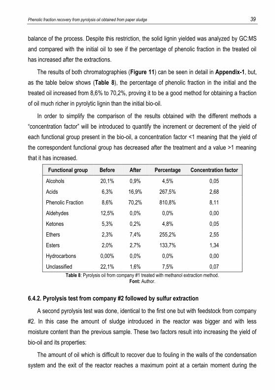
The results of both chromatographies (Figure 11) can be seen in detail in Appendix-1, but,
as the table below shows (Table 8), the percentage of phenolic fraction in the initial and the
treated oil increased from 8,6% to 70,2%, proving it to be a good method for obtaining a fraction
of oil much richer in pyrolytic lignin than the initial bio-oil.
In order to simplify the comparison of the results obtained with the different methods a
“concentration factor” will be introduced to quantify the increment or decrement of the yield of
each functional group present in the bio-oil, a concentration factor <1 meaning that the yield of
the correspondent functional group has decreased after the treatment and a value >1 meaning
that it has increased.
Functional group Before After Percentage Concentration factor
Alcohols 20,1% 0,9% 4,5% 0,05
Acids 6,3% 16,9% 267,5% 2,68
Phenolic Fraction 8,6% 70,2% 810,8% 8,11
Aldehydes 12,5% 0,0% 0,0% 0,00
Ketones 5,3% 0,2% 4,8% 0,05
Ethers 2,3% 7,4% 255,2% 2,55
Esters 2,0% 2,7% 133,7% 1,34
Hydrocarbons 0,00% 0,0% 0,0% 0,00
Unclassified 22,1% 1,6% 7,5% 0,07
Table 8: Pyrolysis oil from company #1 treated with methanol extraction method. Font: Author.
6.4.2. Pyrolysis test from company #2 followed by sulfur extraction
A second pyrolysis test was done, identical to the first one but with feedstock from company
#2. In this case the amount of sludge introduced in the reactor was bigger and with less
moisture content than the previous sample. These two factors result into increasing the yield of
bio-oil and its properties:
The amount of oil which is difficult to recover due to fouling in the walls of the condensation
system and the exit of the reactor reaches a maximum point at a certain moment during the

40 González Rivas, Álvaro
pyrolysis test, and once this maximum is achieved the oil produced afterwards will be
condensed more easily and the yield of both liquid fractions will increase. On the other hand, a
reduced moisture content in the initial bio-oil will mean a decrease in the amount of pyrolytic oil
produced, but the amount of water in this oil will be smaller, meaning that the properties of the
oil will be better.
Phase Weigh [g] Percentage Phase Percentage
Sample mass 1000 - Regarding the organic
First liquid fraction 220,8 22,1% Liquid 56,7%
Second liquid fraction 37,8 3,8% Char 14,2%
Solids remaining in the reactor 608,5 60,8% Gas 29,1%
Gas 132,9 13,3% Inorganic 54,3%
Table 9: Mass balance of the pyrolysis test from company #2. Font: Author.
From the 258,6g produced (Table 9), 204,1g where decanted into a Kitasato flask where
130g of water were added and where the sulfur dioxide was later introduced while stirring. For
producing this sulfur dioxide 9g of sulfur where introduced in the second Kitasato where the
reaction took place, generating 18g of sulfur dioxide. The amounts of sulfur dioxide and water
needed were extrapolated from the experiments disclosed in the patent, in order to benefit from
the previous experiences described and reduce the error in the initial experiments.
Despite that the amount of lignin left unreacted due to moving the oil fraction from one
container to another is very small compared to the one from the previous experiment, it was
considered that the quantity of solids left unreacted inside the condensation system would make
a mass balance of this experiment not representative of the efficiency of the method.
Like in the solvent extraction, a gas chromatography of the initial and the final oil where
compared to see how the amount of phenolic fraction increases after the process. The results
show that amount of phenolic fraction in the samples analyzed has increased from 15,7% in the
initial bio-oil to 55,8% (Table 10).

Phenolic fraction recovery from pyrolysis oil obtained from paper sludge 41
Functional group Before After Percentage Concentration factor
Alcohols 24,3% 7,4% 29,6% 0,30
Acids 0,9% 10,0% 1046,7% 10,47
Phenolic Fraction 15,7% 55,8% 355,9% 3,56
Aldehydes 1,4% 0,4% 26,9% 0,27
Ketones 16,1% 11,5% 71,5% 0,72
Ethers 0,6% 0,2% 38,4% 0,38
Esters 0,3% 7,1% 2366,9% 23,67
Hydrocarbons 0,5% 3,9% 799,9% 8,00
Unclassified 19,5% 3,6% 18,5% 0,18
Table 10: Pyrolysis oil from company #2 treated with SO2 extraction method. Font: Author.
6.4.3. Results of the two initial experiments
Looking into detail the table presented below (Table 11), it is possible to appreciate
significant similarities between the two methods. Both not only increased the amount of pyrolytic
lignin present in the sample, but also increased the amount of acids, ethers and esters and
decreased the yield of alcohols, aldehydes, ketones and the percentage of chemicals grouped
as “unclassified”.
Concentration factor of test
#1
Concentration factor of test
#2
Alcohols 0,05 0,3
Acids 2,68 10,47
Phenolic fraction 8,11 3,56
Aldehydes 0 0,27
Ketones 0,05 0,72
Ethers 2,55 0,38
Esters 1,34 23,67
Hydrocarbons 0 8
Unclassified 0,07 0,18 Table 11: Comparison of the concentration factors of both methods.
Font: Author

42 González Rivas, Álvaro
Both methods proved to have a high efficiency when it comes to remove oxygenated
compounds from pyrolysis oil, especially the solvent extraction using methanol, which
decreased the yield of alcohols, aldehydes and ketones to almost zero. Eventhought both
methods increased the percentage of organic acids, ethers and esters, this increment is
significantly higher when using the extraction with sulfur dioxide. It is also noticeable that the
decrease of the percentage of alcohols and ketones is significantly lower using this method, and
the increase of the yield of the phenolic fraction is lower as well.
These factors are a proof of the feasibility of both methods, but the results obtained when
comparing both separations may indicate that the working conditions used during the second
experiment are probably not the best ones to obtain a good efficiency. In an attempt to obtain
better results using the sulfur reaction method, another experiment was carried on, in which the
bio-oil mixed with water and sulfur dioxide will be heated to 100ºC (in order to reverse the
reaction of formation of acid) after the separation and not before.
6.4.4. Improvement of sulfur extraction
A third pyrolysis test was done, following the same procedure but using a feedstock from a
different company (#3). Like in the previous test, the amount of paper sludge introduced in the
injector is of 1000g in order to yield about 200mL of oil. With bigger amounts of oil, the error
committed during the experiment is smaller, since the percentage of bio-oil which is lost due to
fouling when moving the liquid from one flask to another is smaller.
Phase Weigh [g] Percentage Phase Percentage
Sample mass 1058,8 - Regarding the organic -
First liquid fraction 210,4 19,9% Liquid 54,8%
Second liquid fraction 49,7 4,7% Char 16,9%
Solids remaining in the reactor 664,2 62,7% Gas 28,3%
Gas 134,5 12,7% Inorganic 55,1%
Table 12: Mass balance of the pyrolysis test from company #3. Font: Author
From the 260,1g produced (Table 12), 210,1g where decanted into a Kitasato flask and
mixed with 140g of water were added and where the sulfur dioxide was later introduced while
stirring.

Phenolic fraction recovery from pyrolysis oil obtained from paper sludge 43
Fig
ure 11: C
hemical com
position of bio-oil from com
panies #1 & #2 before (blue) and after (orange) treatm
ent with tw
o different methods to recover a fraction rich in pyrolytic
lignin.
Fo
nt: A
uthor.

44 González Rivas, Álvaro
For producing this sulfur dioxide 14,5g of sulfur where introduced in the second Kitasato where
a “roasting” reaction took place, generating 29g of sulfur dioxide.
Like in the previous experiments, the amount of lignin left unreacted in the condensation
system due to moving the oil fraction from one container to another would make a mass balance
of this experiment not representative of the efficiency of the method.
In this experiment a GC:MS of the aqueous fraction was also done in order to obtain more
information about the efficiency of the method and to know the chemical composition of the
fraction of bio-oil which is not used to obtain pyrolytic lignin with the objective of finding another
use for it. The results show that the amount of pyrolytic lignin in the organic fraction has
increased from 6,5% in the initial bio-oil to 33,7%. The tables below (Tables 13 & 14) show a
comparison between the two experiments done using the sulfur extraction method.
Functional group Before After Percentage Concentration factor
Alcohols 3,9% 9,0% 232,7% 2,33
Acids 0,1% 14,5% 8628,9% 86,29
Phenolic Fraction 6,5% 33,7% 516,4% 5,16
Aldehydes 2,1% 1,9% 94,1% 0,94
Ketones 14,5% 7,6% 52,6% 0,53
Ethers 4,0% 12,3% 309,4% 3,09
Esters 0,2% 0,2% 111,9% 1,12
Hydrocarbons 0,7% 19,1% 2790,4% 27,90
Unclassified 47,9% 1,3% 2,7% 0,03
Table 13: Pyrolysis oil from company #3 treated with SO2 extraction method (organic fraction). Font: Author

Phenolic fraction recovery from pyrolysis oil obtained from paper sludge 45
Functional group Before After Percentage Concentration factor
Alcohols 3,9% 7,5% 193,5% 1,94
Acids 0,2% 2,6% 1532,1% 15,32
Phenolic Fraction 6,5% 1,8% 27,7% 0,28
Aldehydes 2,1% 0,2% 11,6% 0,12
Ketones 14,5% 11,5% 79,4% 0,79
Ethers 4,0% 6,2% 154,7% 1,55
Esters 0,2% 0,0% 0,0% 0,00
Hydrocarbons 0,7% 1,1% 156,5% 1,57
Unclassified 47,9% 49,1% 102,4% 1,02
Table 14: Pyrolysis oil from company #3 treated with SO2 extraction method (aqueous fraction). Font: Author
6.4.5. Results of both sulfur extraction experiments
When comparing the results obtained after repeating the sulfur extraction method with the
first experiment using the same technology, some changes can be appreciated (Table 15).
Concentration factor of test
#2
Concentration factor of test
#3
Alcohols 0,3 2,33
Acids 10,47 86,29
Phenolic fraction 3,56 5,16
Aldehydes 0,27 0,94
Ketones 0,72 0,53
Ethers 0,38 3,09
Esters 23,67 1,12
Hydrocarbons 8 27,9
Unclassified 0,18 0,03 Table 15: Comparison of the concentration factor of both experiments using the sulfur extraction method.
Font: Author
It is clear that the amount of phenolic fraction present in the sample after the second
experiment is bigger, but the amount of acids and hydrocarbons has drastically increased as
well, so this new working conditions are far from being the optimal working conditions of the
process. Focusing on the other functional groups, the percentage of aldehydes, ketones and

46 González Rivas, Álvaro
unclassified components has followed a similar pattern in both experiments, but in the second
experiment, the amount of ethers and alcohols (both oxygenated components) in the final
product has increased. The amount of each functional group can be seen in detail when
comparing the results obtained in both chromatographies (Figure 12). These results show that,
even though the recovered product after the second experiment is richer in phenolic fraction
than the product obtained with the first experience, the quality of the treated oil is worst in the
second case, since it contains bigger amounts of oxygenated compounds and acids, which will
hinder its utilization as substitute of phenol. One positive aspect of the second method is that,
unlike in the first experiment, no presence of sulfur containing components where found in the
final product nor the aqueous phase.
Both experiments done with the sulfur extraction method serve as an initial approach to
studying and optimizing the method, but the results of the experiences indicate that further
investigation needs to be done.
Since one of the advantages of this method is the possibility of recovering the aqueous
fraction without any contaminants introduced during the separation process an analysis of this
phase was also done. As shown in the graph below (Figure 13), pyrolytic oil of paper sludge
from company #3 has an important amount of unclassified compounds. In detail results of this
chromatography can be found in Appendix-1, but this “unclassified” group is mostly composed
of anhydrosugars (specially D-Allose).
This result opens a new route of investigation, since, as mentioned in previous sections of
this project, anhydrosugars present in bio-oil can be hydrolyzed into glucose, from which the
obtainment of bio-oil is possible. Given the scenario that more pyrolytic oil from paper sludge
from different feedstocks is found to contain similar amounts of anhydrosugars, further research
of this method (or other technologies for obtaining chemicals from anhydrosugars present in bio-
oil) should be considered.

Phenolic fraction recovery from pyrolysis oil obtained from paper sludge 47
Fig
ure 12: C
hemical com
position of bio-oil from com
panies #2 & #3 before (blue) and after (orange) treatm
ent with the S
O2 extraction m
ethod to recover a fraction rich in pyrolytic lignin.
Fo
nt: A
uthor.

48 González Rivas, Álvaro
6.4.6. Solvent extraction using a centrifuge
As mentioned before, for deciding which of the two processes for separating bio-oil in two
phases is better, a mass balance is needed in addition to the efficiency of each technology in
recovering the phenolic fraction. Since the methodology that needs to be followed and the
working conditions which optimize the sulfur extraction process are still unclear and need to be
further investigated, an attempt of doing a proper mass balance of the solvent extraction with
methanol and water will be done.
With the help of a centrifuge, it is possible to replicate the agitation and decantation steps
that need to be done during the two step L-L extraction significantly faster than decanting by
gravity. A series of experiments where designed in which the centrifuge was configured to work
at a speed of 3000 rpm for a period of two minutes. This speed and time residence are believed
(based on previous experiments done at Alucha Recycling Solutions) to be enough to ensure a
proper separation of the two phases formed after mixing the bio-oil with water.
Figure 13: Chemical composition of the aqueous phase of bio-oil from company #3 after treatment with the SO2 extraction method to recover a fraction rich in pyrolytic lignin.
Font: Author.
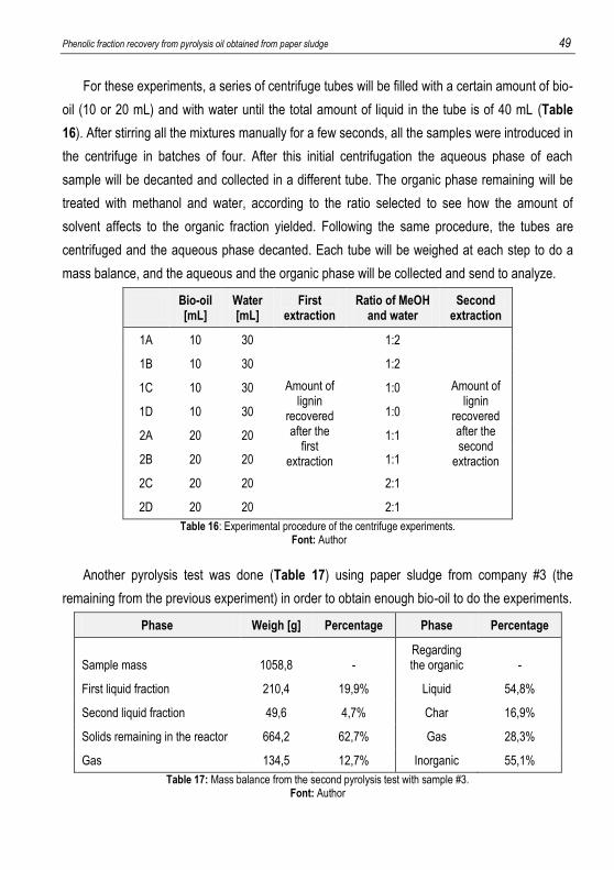
Phenolic fraction recovery from pyrolysis oil obtained from paper sludge 49
For these experiments, a series of centrifuge tubes will be filled with a certain amount of bio-
oil (10 or 20 mL) and with water until the total amount of liquid in the tube is of 40 mL (Table
16). After stirring all the mixtures manually for a few seconds, all the samples were introduced in
the centrifuge in batches of four. After this initial centrifugation the aqueous phase of each
sample will be decanted and collected in a different tube. The organic phase remaining will be
treated with methanol and water, according to the ratio selected to see how the amount of
solvent affects to the organic fraction yielded. Following the same procedure, the tubes are
centrifuged and the aqueous phase decanted. Each tube will be weighed at each step to do a
mass balance, and the aqueous and the organic phase will be collected and send to analyze.
Bio-oil [mL]
Water [mL]
First extraction
Ratio of MeOH and water
Second extraction
1A 10 30
Amount of lignin
recovered after the
first extraction
1:2
Amount of lignin
recovered after the second
extraction
1B 10 30 1:2
1C 10 30 1:0
1D 10 30 1:0
2A 20 20 1:1
2B 20 20 1:1
2C 20 20 2:1
2D 20 20 2:1
Table 16: Experimental procedure of the centrifuge experiments. Font: Author
Another pyrolysis test was done (Table 17) using paper sludge from company #3 (the
remaining from the previous experiment) in order to obtain enough bio-oil to do the experiments.
Phase Weigh [g] Percentage Phase Percentage
Sample mass 1058,8 - Regarding the organic -
First liquid fraction 210,4 19,9% Liquid 54,8%
Second liquid fraction 49,6 4,7% Char 16,9%
Solids remaining in the reactor 664,2 62,7% Gas 28,3%
Gas 134,5 12,7% Inorganic 55,1%
Table 17: Mass balance from the second pyrolysis test with sample #3. Font: Author

50 González Rivas, Álvaro
Figure 15: Detail of the eight samples of oil mixed with water after the first extraction.
Font: Author
A total of 157,8g of oil were produced and 110,2g where decanted into different centrifuge
tubes (Figure 14) in different quantitates (10 or 20mL).
After the first centrifugation, the organic phase of the pyrolysis oil was at the bottom of the
tube as a compacted solid paste with a high content of water (Figure 15), and the aqueous
phase was at the top of the tube. The next step was to remove this aqueous fraction by
decantation and left the solid pyrolytic lignin in the bottom of the tube.
Figure 14: Detail of the eight samples of oil mixed with water before the first extraction.
Font: Author

Phenolic fraction recovery from pyrolysis oil obtained from paper sludge 51
The second extraction was done with a ratio of oil using different ratios of methanol and
water to test the effect that these have on the efficiency of the method. The first experiment,
were the whole pyrolysis oil was treated with this method, was done using the same amount of
water, methanol and bio-oil, as stated in the literature. After weighing the amount of pyrolytic
lignin present in each tube, solutions with different ratios were prepared, measuring the amount
of solvent and water that needed to be added to each tube to fit the specifications.
These samples were treated following the same procedure as in the first extraction and the
centrifuge specifications were also the same ones (3000rpm during 2 minutes). As in the
previous experience, the aqueous phase was decanted, leaving the solid lignin in the bottom of
the tube. A sample from the two decanted water phases (mixed proportionally) and a sample of
the pyrolytic lignin were collected and sent to analyze.
The table below shows the amount of each component used during the different stages of
these experiments and the final amount of lignin recovered, comparing it with the initial bio-oil
introduced in the tube. From these results it is possible to do a mass balance of each
experience and know the efficiency of each of the different ratios used to treat the pyrolytic oil.
In order to understand better the tendency of the results shown above two determinant
factors need to be explained:
1. The pyrolysis oil obtained after the pyrolysis test is always very aqueous and,
eventhought two phases are not always appreciated, the bottom fraction of the oil
is always richer in pyrolytic lignin than the top fraction, which is more aqueous. It
is because of this factor that the efficiency of the extractions is worst in the first
samples (1A and 2A), slightly better in the second ones (1B and 2C) and
significantly better in the last ones (1C and 2C).
2. The yield of pyrolysis oil obtained after the second pyrolysis test done with paper
sludge from company #3 turned out to be insufficient to do all the centrifuge
experiments planned. As a solution, bio-oil from another source, which had been
stored for several months, was used to perform the two last experiments (1D and
2D). This aged bio-oil breaks the upward trend of the efficiency results and seems
to have an amount of pyrolytic lignin similar to samples 1B and 2B respectively.
Once these two points have been clarified, the results can be discussed in detail.

52 González Rivas, Álvaro
Oil
Wat
erTO
TAL
Wat
erLi
gnin
Lign
inM
eOH
Wat
erTO
TAL
Wat
erLi
gnin
1A10
,11
29,8
639
,97
39,0
60,
667%
1:02
0,66
0,78
1,29
2,73
2,34
0,39
4%59
%
1B11
,16
29,0
440
,238
,84
1,31
12%
1:02
1,31
1,34
2,7
5,35
4,11
1,24
11%
95%
1C11
,06
29,1
140
,17
364,
0737
%1:
004,
074,
150
8,22
4,63
3,59
32%
88%
1D10
,19
29,9
540
,14
38,6
41,
4514
%1:
001,
451,
550
32,
310,
697%
48%
2A20
,56
19,5
540
,11
39,0
91,
075%
1:01
1,07
0,98
0,98
3,03
2,12
0,91
4%85
%
2B19
,99
20,2
40,1
938
,61
1,63
8%1:
011,
631,
491,
494,
613,
181,
437%
88%
2C20
,48
19,7
640
,24
33,7
66,
4932
%2:
016,
4913
,12
6,5
26,1
120
,79
5,32
26%
82%
2D20
,41
19,5
39,9
137
,42,
4812
%2:
012,
484,
982,
8110
,27
8,23
2,04
10%
82%
FIR
ST
EX
TRA
CTI
ON
(w
ith w
ater
)E
ffici
ency
of th
e fir
st
extra
ctio
n
Rat
io
MeO
H:
wat
er
SE
CO
ND
EX
TRA
CTI
ON
(w
ith w
ater
and
met
hano
l)E
ffici
ency
of th
e
seco
nd
extra
ctio
n
Per
cent
age
of
pyro
lytic
lign
in le
ft
from
the
first
extra
ctio
n
BE
FO
RE
AF
TER
BE
FO
RE
AF
TER
Tab
le 1
8: M
ass
bala
nce
and
effic
ienc
y of
the
extr
actio
ns o
f pyr
olys
is o
il fr
om c
ompa
ny #
3 do
ne w
ith m
etha
nol a
nd w
ater
usi
ng a
cen
trifu
ge
Fo
nt:
Aut
hor
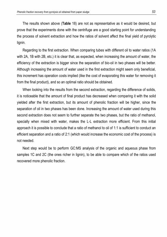
Phenolic fraction recovery from pyrolysis oil obtained from paper sludge 53
The results shown above (Table 18) are not as representative as it would be desired, but
prove that the experiments done with the centrifuge are a good starting point for understanding
the process of solvent extraction and how the ratios of solvent affect the final yield of pyrolytic
lignin.
Regarding to the first extraction. When comparing tubes with different oil to water ratios (1A
with 2A, 1B with 2B, etc.) it is clear that, as expected, when increasing the amount of water, the
efficiency of the extraction is bigger since the separation of bio-oil in two phases will be better.
Although increasing the amount of water used in the first extraction might seem only beneficial,
this increment has operation costs implied (like the cost of evaporating this water for removing it
from the final product), and so an optimal ratio should be obtained.
When looking into the results from the second extraction, regarding the difference of solids,
it is noticeable that the amount of final product has decreased when comparing it with the solid
yielded after the first extraction, but its amount of phenolic fraction will be higher, since the
separation of oil in two phases has been done. Increasing the amount of water used during this
second extraction does not seem to further separate the two phases, but the ratio of methanol,
specially when mixed with water, makes the L-L extraction more efficient. From this initial
approach it is possible to conclude that a ratio of methanol to oil of 1:1 is sufficient to conduct an
efficient separation and a ratio of 2:1 (which would increase the economic cost of the process) is
not needed.
Next step would be to perform GC:MS analysis of the organic and aqueous phase from
samples 1C and 2C (the ones richer in lignin), to be able to compare which of the ratios used
recovered more phenolic fraction.

54 González Rivas, Álvaro

Phenolic fraction recovery from pyrolysis oil obtained from paper sludge 55
7. CONCLUSIONS
An initial approach to the investigation of two methods (solvent extraction using
methanol and water and phase separation injecting sulfur dioxide) to recover the
phenolic fraction present in pyrolysis oil was done. Both methods reported promising
results, being able to obtain a final product rich in phenolic fraction. This phenolic
fraction, as stated in the literature of the project, can be used as a substitute for
traditional phenols in the synthesis of phenol-formaldehyde resins.
Two step liquid-liquid extraction, using water in the first step and a mixture of water
and methanol in the second step, reported promising results for obtaining a final
product rich in phenolic fraction (from the initial 8,6% to 70,2%). An initial mass
balance of the process was done using a centrifuge but further experiments need to
be done.
The sulfur dioxide extraction method succeeded into obtaining a final product richer in
phenolic fraction than the initial bio-oil (from the initial 15,7% to 55,8%), which is a
lower recovery ratio than in the first method, but it cannot be labeled as unsuccessful
until a comparison of the mass balances of both methods is done.
After repeating the sulfur extraction method in order to improve its efficiency, the
amount of phenolic fraction recovered increased (from the initial 6,5% to 33,7%) with
the new operation conditions, but these conditions are far from the optimal since the
percentage of acid and oxygenated compounds increased as well.
Results of the gas chromatography analysis of the aqueous fraction of bio-oil from
paper sludge from company #3 showed an important amount (around 50%) of
anhydrosugars present in the sample. This high yield should encourage the
investigation of possible methods to use this phase as feedstock for chemicals (like
bio-ethanol obtainment through hydrolysis of anhydrosugars).

56 González Rivas, Álvaro
The experiments done with the centrifuge are a good starting point for understanding
the process of solvent extraction and how the ratios of solvent affect the final yield of
pyrolytic lignin.
A feasibility study of each method for its industrial application could not be done since
both processes need to be further investigated in order to fully define the obtained
products and the mass balance of each method.
Phenolic fraction recovery from pyrolysis oil obtained from paper sludge 57
8. NEXT STEPS AND RECOMMENDATIONS
Realization of more experiments using both separation methods in order to define
an accurate mass balance of each process.
Would be advisable to do more analysis of the obtained pyrolysis oil once the bio-
oil starts being produced at the pilot plant instead than at the laboratory scale
reactor.
Improvement of the operation conditions and ratios used in the sulfur extraction
technology.
Further investigation of how the ratio of methanol and water used during the
solvent extraction method affect the final yield pyrolytic lignin and the amount of
phenolic fraction present in it.
Doing an approximate mass balance of the complete process in order to know the
amount of pyrolysis lignin and aqueous fraction that could be obtained regarding a
ton of paper sludge.
Perform an initial study of the economic feasibility of each process, taking into
consideration how the amount of components used at each step affect the cost of
the process.
Start a market study targeting companies that use phenol-formaldehyde resins as
reactant or as product for offering them an alternative and greener phenol source.


Phenolic fraction recovery from pyrolysis oil obtained from paper sludge 59
9. REFERENCES AND NOTES
1. Anders Kallenberg. Liquid bio fuels for gas turbines. Master thesis at Lund University,
2013.
2. Athanasiadou, E. &Papadopoulou, H. “Non-food Crops-to-Industry schemes in EU27” WP1. Non-food crops, 2011, CHIMAR Hellas SA.
3. Balat, M. et al. Main routes for the thermo-conversion of biomass into fuels. Part 1:
pyrolysis systems, 2009
4. Bennett, N. M. et al. Extraction and hydrolysis of levoglucosan from pyrolysis oil.
Bioresource technology, (2009) 100: 6059-6063.
5. Chum, H. L et al. (1993). Phenolic compounds containing neutral fractions extract and product derived therefrom from fractionated fast pyrolysis oil, U.S. Patent 5.223.601.
6. Chum, H. L., and Kreibich R. E. (1992). Process for preparing phenol-formaldehyde resin products derived from fractionated fast-pyrolysis oil, U.S. Patent 5.091.499.
7. Czernik, S., Bridgewater, A.V. Overview of applications of biomass fast pyrolysis oil.
Energy Fuels (2004) 18 (2): 590–598.
8. Elkasabi et al. Characterization of fast-pyrolysis bio-oil distillation residues and their
potential Applications. Journal of analytical and applied pyrolysis (2015) 114: 179-186
9. Garcia-Perez, M; Chaala, A.; Pakdel, H.; Kretschmer, D.; Roy, C., Characterization of
bio-oils in chemical families. Biomass and Bioenergy 2007, 31 (4), 222-242.
10. Jens F. Peters; Diego Iribarren; Javier Dufour. Life cycle assessment of pyrolysis oil
applications. Biomass Conv. Bioref, (2015) 5:1-19.
11. Joseph Anthony Kocal. Acetic acid production from biomass pyrolysis. US Patent
8.716.522 B2 (2014).
12. Kim, J. S. Production, separation and applications of phenolic-rich bio-oil. Bioresource
Technology (2015) 178: 90-98.
13. Lian, J. et al. Separation, hydrolysis and fermentation of pyrolytic sugars to produce
ethanol and lipids. Bioresource Technology (2010) 101: 9688-9699.
14. Luque, L. et al. Pyrolysis based bio-refinery for the production of bioethanol from
demineralized lingo-cellulosic biomass. Bioresource Technology (2014) 161: 20-28.
15. Oasmaa, A.; Czernik, S. Fuel oil quality of biomass pyrolysis oils – state of the art for
the end users. Energy & fuels 1999, 13, 914-921.
16. Prabir Basu, Biomss gasification and pyrolysis. Practical Design and theory (2010)
ISBN: 978-0-12-374988-8.
17. Prakash, R.; Singh, R. K.; Murugan, S. Use of biodiesel and bio-oil emulsions as an
alternative fuel for direct injection diesel engine. Waste Biomass Valor, (2013) 4:475-
484.

60 González Rivas, Álvaro
18. Ramirez Corredores et al. Renewable heating oil. US Patent 8.628.589 B2 (2014).
19. Sanna, A. et al. Hydrodeoxygenation of the aqueous fraction of bio-oil with Ru/C and
Pt/C catalysts. Applied Catalysis B, (2015) Enviromental 165: 446-456.
20. Sukhbaatar, B. et al. Removal of acids from bio-oil. BioResources, (2009) 4: 1319-
1329.
21. Sukhbaatar, B. et al. Use of lignin separated from bio-oil in oriented strand board
binder phenol-formaldehyde resins. BioResources, (2009) 4(2): 789-804.
22. Vecino Mantilla, S. et al. Methodology for the extraction of phenolic compounds of bio-
oil from agricultural wastes. Waste Biomass Valor (2015) 6:371-383.
23. Wang, P. C., Weider, P. R., and Blackbourn, R. L. (2014). Method of separating lignin
derived compounds from pyrolysis oil, U.S. Patent 2014/0259888 A1
24. Wang, S., Gu, Y., Liu, Q., Yao, Y., Guo, Z., Luo, Z., Cen, K., 2009. Separation of bio-oil bymolecular distillation. Fuel Process. Technol. (2009) 90 (5): 738–745.
25. Ye, T. et al. High efficiency production of hydrogen. Catal Lett (2009) 127: 323-333.
26. Zeng, F., Liu, W., Jiang, H., Yu, H.-Q., Zeng, R.J., Guo, Q. Separation of phthalate esters from bio-oil derived from rice husk by a basification-acidification process and column chromatography. Bioresource Technology (2011) 102 (2): 1982–1987.

Phenolic fraction recovery from pyrolysis oil obtained from paper sludge 61
10. ACRONYMS
1. Gasification: Biomass gasification is the conjunction of thermochemical reactions
that are produced in an atmosphere low in oxygen and which results in the
transformation of the solid biomass in a series of combustible gases that can be
used in a combustion engine, a turbine or a motor, after being properly upgraded.
2. Secondary cracking reactions may be present if the product gasses are not rapidly
cooled, making a thermochemical process where the main products are char,
carbon monoxide or methane.
3. Pyrolysis of lignin yields a range of products, being methoxy-substituted phenols
the most characteristic ones but also including simple phenols and oligomeric
polyphenols
4. Selective fast pyrolysis, differed from conventional fast pyrolysis which is usually
aimed at the maximum bio-oil yield, is to drive the pyrolysis of biomass towards
the products of interest, mostly by catalyst utilization, to maximize the yield of
target product and obtain target products with high purity.
5. Gas chromatography is a chemical analysis which separates and identifies
chemicals from a complex sample. A gas chromatograph uses a flow-through
narrow tube known as the column, through which different chemical constituents
of a sample pass in a gas steam (carrier gas) at different rates depending on the
various chemical and physical properties and their interaction with a specific
column filing, called stationary phase. As chemicals exit the end of the column,
they are detected and identified electronically. The function of the stationary
phase in the column is to separate different components, causing each one to exit
the column at different time (retention time).


Phenolic fraction recovery from pyrolysis oil obtained from paper sludge 63
APPENDICES


Phenolic fraction recovery from pyrolysis oil obtained from paper sludge 65
APPENDIX 1: CHROMATOGRAPHY RESULTS AND
FUNCTIONAL GROUP CLASSIFICATION

66 González Rivas, Álvaro
Comapany #1 Test 1 Test 2
Apex RT Area %Area Apex RT Area %Area
Ethanol 4,53 148464345 0,13 4,54 260546867 0,28
Allyl alcohol 6,07 262139799 0,22 6,07 578112116 0,61
1-butanol 8,41 1994496282 1,7 8,41 4071300113 4,33
Furfuryl alcohol 13,63 5229415227 4,46 5,208 13,62 4087922919 4,35 7,656 6,432
Formic acid 6,72 1240018032 1,06 6,69 1299629751 1,38
Acetic acid 7,72 3,2469E+10 27,66 7,66 1,9678E+10 20,93
Propionic acid 9,86 3579125482 3,05 9,82 2727830089 2,9
butyric acid 11,91 988908666 0,84 11,88 497579414 0,53
2-methyl butyric acid 13,38 380187371 0,32 13,37 247823592 0,26
2-pentenoic acid 14,12 223614994 0,19 14,11 174622990 0,19
2-pentenoic acid? 15,3 1416670717 1,21 15,28 1375783221 1,46
trans-2-methyl-2-pentenoic acid 16,98 711018978 0,61 27,952 16,97 571752181 0,61 22,608 25,28
pyrazine 9,96 477511829 0,41 9,96 568039848 0,6
pyridine 10,43 1024947931 0,87 10,41 280672637 0,3
methyl pyrazine? 12,17 865715712 0,74 12,15 969513839 1,03
Furfural 13,06 4583857166 3,91 13,06 6696346693 7,12
2-ethylfurane 13,88 102949606 0,09 13,88 238423821 0,25
4,6-dimethylpyrimidine 14,2 199805902 0,17 14,2 550742208 0,59
Ethylpyrazine 14,31 336496156 0,29 14,29 308763991 0,33
2,3-dimethylpyrazine 14,35 127950818 0,11 14,35 90846388,2 0,1
phenol 17,41 1155063505 0,98 17,41 667729343 0,71
2-methylphenol (o-cresol) 18,7 677630649 0,58 18,7 379598058 0,4
2-methoxyphenol 18,93 2297691678 1,96 18,93 1320299651 1,4
3-methylpenol (m-cresol) 19,26 717269637 0,61 19,26 409346107 0,44
2,5-xylenol 19,55 225690494 0,19 19,54 135858462 0,14
2,4-xylenol 20,47 320984642 0,27 20,47 178472571 0,19
2-methoxy-p-cresol 21 1228122594 1,05 21 672565361 0,72
p-Ethylguaiacol 22,64 400496671 0,34 22,65 190537093 0,2
3-Allyl-6-methoxyphenol 24,31 55332453 0,05 10,096 24,31 36730583,5 0,04 11,648 10,872
Acetaldehyde 3,77 549320748 0,47 3,78 290308226 0,31
Acrolein 4,89 4755108,04 0 4,88 26481739,1 0,03
Propionaldehyde 4,93 84425682,9 0,07 4,93 30810913 0,03
Isobutyraldehyde 5,96 68241625,9 0,06 5,96 7509780,83 0,01
Crotonaldehyde 8,22 121211008 0,1 8,22 218064544 0,23
o-methyloxime butanal ? 11,14 856267916 0,73 11,12 848553530 0,9
3-furaldehyde 12,38 193808991 0,17 12,38 475896101 0,51
5-methyl-2-furan-carboxaldehyde 16,21 1710217701 1,46 2,448 16,21 1654237499 1,76 3,024 2,736
Acetone 5,02 398149182 0,34 5,02 745340299 0,79
2-butanone 6,81 179681594 0,15 6,83 328334021 0,35
1-penten-3-one 8,8 70501945,2 0,06 8,8 28981335,3 0,03
2-pentanone 8,83 24016853,6 0,02 8,85 39184253,8 0,04
1-hydroxy-2-propanone 9,14 1,4254E+10 12,14 9,09 1,1265E+10 11,98
3-hydroxy-2-butanone 10,11 1264292465 1,08 10,09 1081674404 1,15
3-pentan-2-one 10,34 516715318 0,44 10,34 584876024 0,62
1-hydroxy-3-butanone 11,54 2009907676 1,71 11,52 1577134803 1,68
cyclopentanone 11,86 343839098 0,29 11,84 798209061 0,85
1-hydroxy-2-butanone 13,5 61962300,8 0,05 13,49 73223546,6 0,08
1-acetyloxy-2-propanone 13,79 3361653512 2,86 13,79 2329261322 2,48
6,10-dimethyl-5,9-dodecandien-2-one 14,01 682770423 0,58 14,01 673734449 0,72
Dihydro-2H-pyran-3(4H)one 14,21 162911406 0,14
cyclohexanone 14,53 42560456,3 0,04 14,53 99581632,4 0,11
2-methyl -cyclopentenone 14,7 1477882618 1,26 14,7 1770216196 1,88
1-(2-furanyl-ethanone) 14,85 1361094228 1,16 14,85 1200925190 1,28
2,5-hexanedione 15,54 382014456 0,33 15,54 211844756 0,23
2-cyclohexen-1-one 15,65 268377474 0,23 15,65 301507629 0,32
2,3-pentanedione 15,9 1595875127 1,36 15,9 1170910237 1,25
1-acetyloxy-2-butanone 15,96 1259535262 1,07 15,95 897014891 0,95
butyrolactone 16,09 685002702 0,58 16,09 433064073 0,46
2(5H)furanone 16,16 625821679 0,53 16,15 373315322 0,4
1-methyl-cyclopenten-3-one 16,62 1339390580 1,14 16,62 860042050 0,91
3,4-dimethyl-2-cyclopenten-1-one 17,05 241032076 0,21 17,05 190875696 0,2
3-methyl-1,2-cyclopentanedione 17,7 1907691984 1,63 17,7 1147313210 1,22
2,3-dimethyl-2-cyclopenten-1-one 18,01 785824264 0,67 18,01 558126575 0,59
2,3,4-trimethyl-2-cyclopenten-1-one 18,3 191622799 0,16 18,3 113500649 0,12
Acetophenone 18,5 360345586 0,31 18,5 227927562 0,24
3-ethyl-2-hydroxy-2-cyclopenten-1-one 19,64 135513119 0,12 19,64 123710759 0,13
(4E)-6-Ethyl-7-hydroxy-4-octen-3-one 19,69 101497585 0,09 19,69 87290126,5 0,09
1-Indanone 23,36 93802159,8 0,08 24,664 23,36 36976356,3 0,04 24,952 24,808
Methyl formiate 4,06 12885438,2 0,01 0,008 4,07 27695068,5 0,03 0,024 0,016
Acetic acid vinil ester 6,64 2030777439 1,73 6,64 2044598285 2,17
Glycolic acid methyl ester 9,59 139972794 0,12 9,57 106372822 0,11
Pyruvic acid methyl ester 12,05 117959871 0,1 12,06 170510858 0,18
2-hydroxy-butyric acid methyl ester 12,56 84758668,6 0,07 1,616 12,56 95854044,7 0,1 2,048 1,832
3,3,4,4-tetramethylhexane 12,7 357491268 0,3 0,24 12,7 321969473 0,34 0,272 0,256
Propanenitrile 6,92 13324282,8 0,01 6,92 50372998,2 0,05
Ethylene glycol monoacetate 11,28 913246668 0,78 11,26 1164487187 1,24
N-(3-hydroxypropyl)guanidine 11,98 425752697 0,36 11,99 349241267 0,37
isobutyric anhydride 12,76 750672749 0,64 1,432 12,76 637683389 0,68 1,872 1,652
? 7,21 87060571,9 0,07 7,18 125411651 0,13
? 12,27 191253457 0,16 12,27 161434811 0,17
? 12,81 367370288 0,31
? 13,68 1119024434 0,95
? 14,78 404222866 0,34 14,78 302753516 0,32
? 15,04 187043359 0,16 15,03 289182010 0,31
? 15,12 201606870 0,17 15,11 241736042 0,26
? 15,73 231116289 0,2
? 16,81 1950197687 1,66 16,81 1182224930 1,26
? 18,13 222625972 0,19 3,368 18,13 157872825 0,17 2,096 2,732
96,29 95,25 76,616

Phenolic fraction recovery from pyrolysis oil obtained from paper sludge 67
Company #2 Test 3 Test 4
Apex RT Area %Area Area %Area
Ethanol 4,53 156768321 0,19 753938002 0,89
allylic alcohol 6,07 674267600 0,82 3427494764 4,07
1-butanol 8,41 929954718 1,14 6015570131 7,14
2-buten-1-ol 8,54 12316373,7 0,02 131909412 0,16
furfuryl alcohol 13,62 4000222244 4,89 2517847608 2,99
2,5-dimethylcyclohexanol 14,78 163282888 0,2 188556505 0,22
4-methyl-4-hepten-3-ol 15,54 212686476 0,26 239058119 0,28
2-ethyl-1-hexanol 16,94 167442956 0,2 6,176 204607780 0,24 12,792 9,484
Formic acid 6,74 198254273 0,24
Acetic acid 7,67 2,1402E+10 26,14 1,024E+10 12,15
Propionic acid 9,85 4097928235 5 2393029271 2,84
butyric acid 11,9 1004293853 1,23 286462078 0,34
3-butenoic acid 12 644002724 0,79 398034304 0,47
2-methyl hexanoic acid 13,36 190530247 0,23 26,904 103743099 0,12 12,736 19,82
2-methoxytetrahidrofuran 9,97 516858685 0,63 958558982 1,14
pyridine 10,38 240515101 0,29
toluene 10,42 312108415 0,38 208583730 0,25
methyl pyrazine 12,15 550138386 0,67 314930276 0,37
Ethylbenzene 12,82 588052116 0,7
furfural 13,06 3650138759 4,46 4489012077 5,33
styrene 13,71 1094843494 1,3
cumene 14,2 228333417 0,28 319015423 0,38
alfa-methylstyrene 15,74 64283986,5 0,08 507758461 0,6
2-propyltetrahydrofuran 16,8 1740028399 2,13 1465086542 1,74
Phenol 17,41 1501836252 1,83 1355173043 1,61
Indene 17,62 117908447 0,14 219138600 0,26
o-cresol 18,69 950011529 1,16 920923106 1,09
o-methylphenol 18,93 500477288 0,61 352987084 0,42
m-cresol 19,26 634639276 0,78 600307661 0,71
2,6-xylenol 19,55 367305515 0,45 288826473 0,34
2-methyl-1H-indene 19,8 63680480,3 0,08 154094937 0,18
1,4-dihydronaphtalene 20,01 122899872 0,15 155045411 0,18
o-ethylphenol 20,29 75725528,4 0,09 100563151 0,12
3,4-xylenol 20,47 367326398 0,45 347259174 0,41
Naphtalene 20,9 122062135 0,15 188992702 0,22
2,5-xylenol 21,35 76502741,7 0,09 98715861,2 0,12
6-ethyl-m-cresol 22,15 111063239 0,14 181222697 0,22
biphenyl 24,72 140639902 0,17 12,152 343250318 0,41 15,304 13,728
Acetaldehyde 3,77 131384817 0,16 302073478 0,36
Acrolein 4,88 41837848 0,05 168701767 0,2
3-furaldehyde 12,38 202215045 0,25 555231368 0,66
2-ethylbutanal 14 166616007 0,2 169049868 0,2
5-methylfuraldehyde 16,21 1218810299 1,49 1,72 1121191164 1,33 2,2 1,96
acetone 5,02 159028399 0,19 1499999903 1,78
2,3-butanedione 6,65 1215203660 1,48 3646498827 4,33
2-butanone 6,82 40163841,7 0,05 566214547 0,67
1-penten-3-one 8,8 67728881,9 0,08 197734472 0,23
2-pentanone 101686351 0,12
2,3-pentanedione 9,02 1729967328 2,11 356764308 0,42
1-hydroxy-2-propanone 9,09 6995995480 8,54 5919729815 7,02
3-hydroxy-2-butanone 10,09 1526587746 1,86 1049419805 1,25
3-penten-2-one 10,34 500083169 0,61 1494725316 1,77
1-hydroxy-2-butanone 11,52 2031714942 2,48 1028088748 1,22
cyclopentanone 11,85 941688498 1,15 3749537100 4,45
2-hexen-4-one 12,56 113192528 0,14 252667240 0,3
2-methyl-cyclopentanone 12,99 249533494 0,3 472600185 0,56
2-cyclopenten-1-one 13,18 3249600756 3,97 3182240991 3,78
3-methyl-cyclopenten-1-one 13,25 75746787,5 0,09
1-acetyl-oxy-2-propanone 13,79 2220838373 2,71 1287648329 1,53
3-methyl-2-cyclopenten-1-one 13,87 179754828 0,22 440646480 0,52
cyclohexanone 14,53 132466574 0,16 265227000 0,31
2-methyl-cyclopentanone 14,7 1967931025 2,4 2436665590 2,89
2-furyl-methylketone 14,85 966900687 1,18 1133046367 1,34
n-propylbenzene 15,03 41484118,8 0,05 142062884 0,17
3,4-dimethyl-2-cyclopenten-1-one 15,25 289535801 0,35 322828066 0,38
cyclohexen-2-en-1-one 15,65 495479716 0,61 429145111 0,51
2,3-pentanedione 15,89 624912237 0,76 411670475 0,49
1-methyl-cyclopenten-3-one 16,61 879571136 1,07 735958919 0,87
3,4-dimethyl-2-cyclopenten-1-one 17,05 276491053 0,34 261993429 0,31
3-methyl-1,2-cyclopentanedione 17,7 722452133 0,88 682419950 0,81
2,3-dimethyl-cyclopenten-1 one 18 742974263 0,91 637094897 0,76
2,3,4-trimethyl-2-cyclopenten-1-one 18,29 141645281 0,17 150055655 0,18
acetophenone 18,5 358857845 0,44 352990538 0,42
2,3,4-trimethyl-2-cyclopenten-1-one 19,07 290966846 0,36 28,456 247252900 0,29 31,816 30,136
1,4-dioxane 0 139305308 0,17 0,136 0,068
glycolic acid methyl ester 9,57 148976711 0,18 89986397 0,11
piruvic acid methyl ester? 10,19 0,144 143167893 0,17 0,224 0,184
1-phenyl-cyclopentene 22,63 68701627,8 0,08 139598546 0,17
1-methylnaphtalene 23,08 41864485,1 0,05 145360488 0,17
2-methylnaphtalene 23,49 112307793 0,14 306074184 0,36
1,7-dimethylnaphtalene 25,96 30764320,6 0,04 69744147,4 0,08
2,6-dimethylnaphtalene 26,08 15668594,1 0,02 36972393 0,04
1,2-dimethylnaphtalene 26,57 19501762,5 0,02 0,064 76606536,9 0,09 0,136 0,1
acetic acid hydrazide 5,32 47589177 0,06 518546933 0,62
Ethylene glycol monoacetate 11,26 341243541 0,42 298573950 0,35
tertbutylhydroperoxide 12,27 257961783 0,32 0,64 199231491 0,24 0,968 0,804
? 8 122058828 0,15
? 8,23 67671516,6 0,08 512634764 0,61
? 10,79 310863411 0,38 293030571 0,35
? 12,44 208269545 0,25 108316203 0,13
? 14,17 193507560 0,24 160283873 0,19
? 14,29 50006398,9 0,06 378056160 0,45
? 15,11 83681551,2 0,1 78398481,6 0,09
? 15,94 374816666 0,46 218132630 0,26
? 16,08 523980815 0,64 570726212 0,68
? 16,31 112190662 0,14 75154824 0,09
? 16,89 96077522,2 0,12 114802690 0,14
? 17,17 55355522,4 0,07 64705515,3 0,08
? 18,13 128702088 0,16 101237326 0,12
? 25,33 57126719,3 0,07 2,336 154687946 0,18 2,696 2,516
98,24 98,76
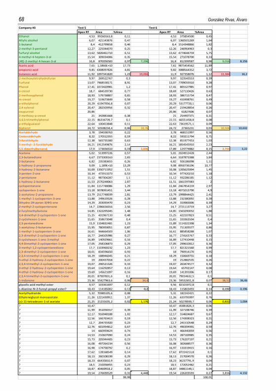
68 González Rivas, Álvaro
Company #3 Test 5 Test 6
Apex RT Area %Area Apex RT Area %Area
Ethanol 4,53 99260163,8 0,11 4,53 375854500 0,45
Allylic alcohol 6,07 421143876 0,47 6,07 1360501269 1,64
1-butanol 8,4 412799658 0,46 8,4 1514348866 1,82
2-methyl-3-pentanol 12,27 225044070 0,25 12,26 246964963 0,3
furfuryl alcohol 13,62 5826461710 6,51 13,62 4774644759 5,75
4-methyl-4-hepten-3-ol 15,54 309034006 0,35 15,54 271078700 0,33
(4E)-2-methyl-4-hexan-3-ol 16,8 870056583 0,97 7,296 16,8 812399587 0,98 9,016 8,156
Acetic acid 7,65 1,5866E+10 17,73 7,61 9875454562 11,89
propionic acid 9,85 4308097826 4,81 9,82 3088564352 3,72
butanoic acid 11,92 1097341820 1,23 19,016 11,9 927358076 1,12 13,384 16,2
2-methoxytetrahydrofuran 9,97 269522767 0,3 9,97 323543553 0,39
Furfural 13,07 7968558171 8,91 13,07 7709059310 9,28
Phenol 17,41 1072420981 1,2 17,41 805527985 0,97
o-cresol 18,7 684539730 0,77 18,69 527110426 0,63
2-methoxyphenol 18,93 579738807 0,65 18,93 386715734 0,47
m-cresol 19,27 519673849 0,58 19,27 410498761 0,49
o-ethylphenol 20,29 61947056,8 0,07 20,29 53177720,1 0,06
2,4-xylenol 20,47 282503956 0,32 20,47 219428854 0,26
oxypurinol 20,86 20,86 61827606 0,07
2-methoxy-p-cresol 21 342881668 0,38 21 254497371 0,31
3,4,5-trimethylphenol 22,15 86316739,7 0,1 22,15 66551458,8 0,08
p-ethylguaiacol 22,64 100453848 0,11 22,63 73619571,1 0,09
Biphenil 24,72 50508234,4 0,06 10,76 24,72 27365231 0,03 10,504 10,632
Acetaldehyde 3,78 194338763 0,22 3,78 468151997 0,56
Crotonaldehyde 8,22 170312355 0,19 8,22 593211794 0,71
3-furaldehyde 12,38 565735300 0,63 12,38 851977453 1,03
5-methyl--2-furaldehyde 16,21 1912549876 2,14 16,21 1854545910 2,23
5,5-dimethylhexanal 17,9 173656510 0,19 2,696 17,89 124774882 0,15 3,744 3,22
Acetone 5,02 513997226 0,57 5,01 2024912428 2,44
2,3-butanedione 6,67 2373300163 2,65 6,64 3187873388 3,84
2-butanone 6,82 235383655 0,26 6,82 926186098 1,11
1-hydroxy-2-propanone 9,09 1,189E+10 13,29 9,08 8950736196 10,77
3-hydroxy-2-butanone 10,09 1350711952 1,51 10,08 1205625994 1,45
3-penten-2-one 10,34 472913373 0,53 10,34 977420210 1,18
2-pentanone 11,12 987304287 1,1 11,12 932286185 1,12
1-hydroxy-2-butanone 11,53 2570248063 2,87 11,51 1661597083 2
cyclopentanone 11,84 1157748086 1,29 11,84 2467854159 2,97
cyclopenten-1-one 13,18 3078061451 3,44 13,18 4071013790 4,9
1-acetyloxy-2-propanone 13,79 2517748039 2,81 13,79 1998844425 2,41
1-methyl-1-cyclopenten-3-one 13,88 249619326 0,28 13,88 232380092 0,28
Dihydro-2H-pyran-3(4H)-one 14,29 203093470 0,23 14,29 319983006 0,39
2-methyl-2-cyclopentenone 14,7 2286656016 2,56 14,7 2721113719 3,27
2-furylmethylketone 14,85 1322295045 1,48 14,85 1563290032 1,88
3,4-dimethyl-2-cyclopenten-1-one 15,25 431967133 0,48 15,25 422107823 0,51
2-cyclohexen-1-one 15,65 358673048 0,4 15,65 333363504 0,4
2,3-pentanedione 15,9 1104832481 1,23 15,89 1114322398 1,34
1-acetyloxy-2-butanone 15,95 780959051 0,87 15,95 711305577 0,86
1-methyl-1-cyclopenten-3-one 16,61 944664503 1,06 16,61 885858288 1,07
2,3-dimethyl-2-cyclopenten-1-one 16,77 244505986 0,27 16,77 274163767 0,33
3-cyclohexen-1-one-3 methyl 16,89 140929661 0,16 16,89 127410448 0,15
4,4-Dimethyl-2-cyclopenten-1-one 17,05 258106873 0,29 17,05 299632812 0,36
3-methyl-1,2-cyclopentanedione 17,7 1103969232 1,23 17,7 821321560 0,99
2,3-dimethyl-2-cyclopenten-1-one 18,01 834596650 0,93 18 790914170 0,95
2,3,4-trimethyl-2-cyclopenten-1-one 18,29 188946045 0,21 18,29 150669755 0,18
3-ethyl-2-hydroxy-2-cyclopenten-1-one 19 200437018 0,22 19 212882535 0,26
2,3,4-trimethyl-2-cyclopenten-1-one 19,07 296521326 0,33 19,07 263474577 0,32
3-ethyl-2-hydroxy-2-cyclopenten-1-one 19,64 116292857 0,13 19,64 65702147 0,08
4-ethyl-2-hydroxy-2-cyclopenten-1-one 19,69 145621097 0,16 19,69 141391006 0,17
2,3,4-trimethyl-2-cyclopenten-1-one 20,01 87907831,6 0,1 20,01 79014632,5 0,1
1-Indanone 23,36 55427963,6 0,06 34,4 23,36 59532651,8 0,07 38,52 36,46
glycolic acid methyl ester 9,57 103361697 0,12 9,56 82101972,8 0,1
L-Alanine-N-2-furoyl-propyl ester? 18,43 114185002 0,13 0,2 18,43 115803493 0,14 0,192 0,196
Acetylhydrazide 5,32 70985105,6 0,08 5,31 182242421 0,22
Ethyleneglycol monoacetate 11,26 1221430911 1,37 11,26 633795997 0,76
(z)-11-tetradecen-1-ol acetate 21,25 21231635,2 0,02 1,176 21,24 50278939,7 0,06 0,832 1,004
? 10,47 10,47 45881826,3 0,06
? 11,99 351056557 0,39 11,99 327198746 0,39
? 12,17 916948188 1,02 12,17 554604687 0,67
? 12,56 166763413 0,19 12,56 174308323 0,21
? 12,7 204735920 0,23 12,7 241510548 0,29
? 12,76 601954812 0,67 12,76 490394991 0,59
? 14 660959624 0,74 14 466440059 0,56
? 14,53 210607090 0,24 14,53 287169985 0,35
? 15,73 205944405 0,23 15,73 176207197 0,21
? 16,08 497264234 0,56 16,08 302688577 0,36
? 16,98 174758792 0,2 16,97 133319415 0,16
? 17,62 128168549 0,14 17,62 87224213,8 0,1
? 18,13 260108199 0,29 18,13 217004570 0,26
? 18,23 66435810,9 0,07 18,23 36237791,9 0,04
? 18,5 210058455 0,23 18,5 172052482 0,21
? 18,87 40469918,2 0,05 18,87 34861149,1 0,04
? 19,54 276690529 0,31 4,448 19,54 226203593 0,27 3,816 4,132
99,99 100,01

Phenolic fraction recovery from pyrolysis oil obtained from paper sludge 69
Alucha project I (12/11/2015)
oil from paper sludge from company #1 before treatment
Peak R.Time Area Percentage Component
9 8,166 1778907 1,551% 2-octen-1-ol
11 8,457 166700 0,145% 4-methyl-cis-cyclohexanol
18 9,265 5371462 4,684% 1,10-decanendiol
21 9,992 933272 0,814% cis-1,2-cyclododecanendiol
22 10,171 156073 0,136% 2,2-dimethyl-1-pentanol
27 10,789 1489227 1,299% cyclodecanol
29 11,134 210202 0,183% 5-methyl-pyrimidine-4,6-diol
31 11,394 1275688 1,112% 2,6-dimethyl-7-octen-3-ol
41 13,793 14551512 12,690% 1,2-benzendiol 20%
53 17,121 2951278 2,574% 7-hexadeyn-1-ol 25,189% 20,15%
3 6,182 3315 0,003% octanoic acid
4 6,224 4002 0,003% 7-oxo-octanoic acid
5 6,384 225518 0,197% 2-noneonic acid
6 6,503 11208 0,010% 2-methylcyclopropanecarboxylic acid
16 8,91 184486 0,161% 1,2-Dimethylcyclopropanecarboxylic acid
39 13,172 1328597 1,159% 3-heptenoic acid
54 17,418 853096 0,744% cyclohexanepropanoic acid
56 17,963 6448231 5,623% 3-ethyl-2-butenoic acid 7,900% 6,32%
12 8,549 109395 0,095% decahydropyrazine
17 9,007 55222 0,048% 2,4-dimethil furan
19 9,648 3620687 3,157% 3-methyl-phenol
23 10,317 151346 0,132% 3-methyl-phenol
45 14,493 768127 0,670% octahydro-44,5-dimethyl-2(1H)-Naphtalenone
49 15,382 246507 0,215% hexahydro-3-methylene-2(3H)-benzofuranone
51 15,89 189920 0,166% 2-piperidinemethanol
52 15,999 7267576 6,338% 3,5-dimethyl-2-furylmethylketone 10,821% 8,66%
13 8,59 9727 0,008%
26 10,681 1112990 0,971%
30 11,21 291573 0,254% 3-methyl-dimethylhydrazone-2-butenal
57 18,526 189507 0,165%
58 19,647 1371465 1,196%
59 20,35 15019465 13,098% 15,693% 12,55%
1 4,633 7683 0,007% 2-cyclopenten-1-one
14 8,716 805778 0,703%
20 9,861 549750 0,479%
33 11,755 1872967 1,633% tetrahydro-4-(2-methyl-1-propen-3-yl)-2H-pyran-2-one
34 11,825 119313 0,104% 2,6-dimethyl-1-(methyl-1-piperazinyl-4(1H)-pyridinone
37 12,73 469914 0,410%
42 13,97 592683 0,517%
44 14,123 859882 0,750% Dihydro-3-methyl-2,4(1H-3H)-pyrimidendione
46 14,858 365320 0,319%
47 14,93 337800 0,295% decahydro-3-2H-cyclopentacyclocteno-2-one
48 15,168 280876 0,245%
61 26,612 1285541 1,121% 2-hydroxy-3,5,5-trimethyl-cyclohexe-2-one 6,582% 5,27%
10 8,231 12155 0,011%
32 11,573 1386131 1,209% 2-(1-methylpropyl)-bicyclo(2,2,1)heptane
36 12,353 1649912 1,439%
38 12,992 41746 0,036%
60 25,179 1044276 0,911% 3,605% 2,88%
50 15,788 2911094 2,539% 2,539% 2,03%
2 4,676 13358 0,012% 3-(1-methylethoxy)-propanennitrile
7 7,669 15415516 13,443% 1,3-dihydroxy-2-cycloheptano(d)imidazolidine
8 8,038 5581 0,005% 2,3,6-tri-O-methyl-glucose
24 10,538 3132138 2,731% 1-ethyl-2-methyl-1H-imidazole
25 10,643 703168 0,613% 1-methyl-2,5-pyrrolidinedione
28 10,902 90776 0,079% 3-ethyl-1,3-dimethyl-2,5-pyrrolidinedione
35 11,965 5171076 4,510% 1-(3-oxobutyl)-3,3-pentanebuthyl enediaziridine
40 13,383 3319153 2,895% 2-methoxy-1,3-benzodiozole
43 14,064 1075014 0,937% Anydro-d-mannosam
55 17,704 2805268 2,446% D-allose 27,672% 22,14%
114670150 100,0%
water
content of
4-noneonic acid methyl ester
O-methyloximedecanal
8-octandecanal
(z)-9-octadecenal
(E)-2-tridecenal
14-methyl-(z)-8-hexadecenal
3-ethenyl-3-methylcyclopentanone
Benzencyclohectanone
octamethyl-cyclotetrasyloxane
dodecyl-oxirane
1,2-dipropyl-cyclopentane
2-ethyl--cycloexanone
Hydroquinone
1,3-benzodioxin-4-one
(1,1-dimethylbutyl)-oxirane
1-(1H-pyrrol-2-yl)-Ethanone

70 González Rivas, Álvaro
Alucha project II (13/11/2015)
oil from paper sludge from company #2 before treatment
Peak R.Time Area Percentage Component
1 4,277 5475421 1,412% 4-cyclohexane-1,2-diol
3 4,61 1570245 0,405% 2-methyl-4-hexen-3-ol
7 6,175 2273821 0,586% 1,2,3-cyclopentanetriol
12 6,692 1517264 0,391% 2-methyleneciclopentanol
14 7,011 696473 0,180% 5-octen-1-ol
16 7,186 338038 0,087% 3-decen-1-ol
20 7,675 10957745 2,825% 2-ethylcyclohexanol
21 7,725 613265 0,158% 1-nonen-3-ol
25 8,493 901631 0,232% 5-octen-1-ol
27 8,726 1029452 0,265% 3-methylcyclopentanol
28 8,908 3173167 0,818% cis-4-methyl-cyclohexanol
38 10,817 977485 0,252% 2-(1-methylethyl)-cyclohexanol
40 11,14 4001423 1,032% 1-none-3-ol
43 11,873 5634208 1,453% 2-methyl-2-octen-4-ol
44 12,292 3415252 0,881% 4-isopropulidene-cyclohexanol
46 13,252 5231410 1,349% 2,3,6-dimethylhept-6-en-1-ol
48 13,754 47804449 12,326% 1,2-benzendiol
49 13,967 15206621 3,921% 2,7-dimethyl-4,5-octanediol
56 17,014 3392559 0,875% 2-methyl-1,4-benzenediol
58 17,825 6850860 1,766% 4-ethyl-1,2-benzendiol 31,216% 24,97%
5 4,808 532355 0,137% cyclopentanedecanoic acid
6 4,933 203636 0,053% octanoic acid
10 6,442 980774 0,253% 4-hydroxy-butanoic acid
17 7,375 367190 0,095% 4-pentenoic acid
19 7,476 340443 0,088% 7-oxo-octanoic acid
30 9,2 620714 0,160% octyl ester hexanoic acid
62 28,601 1607684 0,415% Hexadecanoic acid 1,200% 0,96%
2 4,483 380762 0,098% 4-hydroxyproline
9 6,368 2065235 0,533% 1-(2-fuanyl)-ethanone
11 6,5 6836000 1,763% 2-(5H)-furanone
18 7,417 203474 0,052% 2-(3-butynyloxy)tetrahidro-2H-pyran
22 8,025 3394567 0,875% 3-methyl-2,5(H)-furanone
23 8,172 9127154 2,353% Phenol
26 8,592 2046795 0,528% 2,5-dihydro-3,5-dimethyl-2-furanone
36 10,525 15884223 4,096% 3-methylphenol
51 14,417 10816293 2,789% 5-hydroxymethyl-2-furane
52 15,075 10846330 2,797% 2-ethoxy-4-methylphenol
54 15,8 8591787 2,215% 4-methylphenol
57 17,142 3315529 0,855% 2,3-dimethylhydroquinone
61 23,225 2519453 0,650% 1,1'-(1,3-propanedyil(bis)benzene 19,604% 15,68%
13 6,783 4503471 1,161% 2-ethyl-2-butenal
47 13,375 2225184 0,574% 3,4-dimethyl-3-cyclohexen-1-carboxaldehyde 1,735% 1,39%
8 6,242 6780210 1,748%
29 9,075 2940795 0,758%
31 9,411 48262779 12,445%
32 9,52 4130870 1,065%
34 10,075 3383625 0,872%
35 10,375 780157 0,201%
37 10,692 1850183 0,477%
42 11,633 9423494 2,430%
45 12,817 608071 0,157% 20,154% 16,12%
15 7,075 1111930 0,287%
33 9,7 1496925 0,386%
53 15,683 109404 0,028% 0,701% 0,56%
24 8,392 1446717 0,373% 3,5-dimethylcyclohexil ester 0,373% 0,30%
55 16,214 2397159 0,618% 2-ethyldione-6-methyl-3,5-heptadienal 0,618% 0,49%
4 4,663 11643497 3,002% 4,5-dimethyl-1H-imidazole
39 10,983 2281770 0,588% 3,4-anhydro-D-galactosan
41 11,498 9308262 2,400% Maltol
50 14,291 62235920 16,048%
59 22,217 3254200 0,839% Glucopyranose
60 22,858 5906497 1,523% galactofuranose 24,400% 19,52%
387822307 100,0%
water
content of
20%
2,3-dimethyl-2-pentene
2-methyl-2-cyclopenten1-one
3-methylpiridazin-5-one
3-methyl-1,2-cyclopentanedione
2,3-dimethyl-2-cyclopentanedione
2,4-dimethyl-1-cyclopentanedione
5,5-dimethyl-cyclohex-3-en-1-one
furylhydroxymethylketone
3-ethyl-2-hydroxy-2-cyclopenten-1-one
5,9-dymethyl-5,8-decadien-2-one
4-methyl-2-hexene
1,2-dimethyl-cycloctene
anhydro-D-mannosan

Phenolic fraction recovery from pyrolysis oil obtained from paper sludge 71
Alucha project III (16/11/2015)
oil from paper sludge from company #1 after treatment
Peak R.Time Area Percentage Component
20 14,952 1795684 0,803% 3,5-dimethylbenzenemethanol
28 16,417 251948 0,113% alpha-1-propenyl-benzanemethanol 0,916%
1 7,002 933386 0,417% trans-2-pentenoic acid
3 9,092 2935325 1,313% 1,2-dimethylcyclopropane carboxylic acid
47 28,042 8654461 3,871% 2,6-dihexadecanoate-1-(t)-ascorbic acid
48 28,683 14589162 6,525% 1-hexadecanoicacid
53 37,136 10699255 4,785% 1,2-benzenedicarboxilic acid 16,911%
2 8,17 2340293 1,047% phenol
5 9,65 157474 0,070% 3-phenyl-1-propine
6 10,458 9359786 4,186% 3-methyl phenol
7 11,217 614218 0,275% 2,6-dimethylphenol
8 12,25 6104155 2,730% 2,5-dimethylphenol
9 12,633 664309 0,297% (1-methylene-2-propenyl)benzene
10 12,733 3600300 1,610% 3-ethylphenol
11 13,108 2425276 1,085% Azulene
14 13,975 661930 0,296%
15 14,175 1109544 0,496% 2-ethyl-6-methyl-phenol
17 14,433 2268826 1,015% 2-ethyl-5-methylphenol
18 14,508 1655895 0,741% hexahydronaphtalene
22 15,3 738435 0,330% 1,2-dihydro-3-methylnaphtalene
23 15,7 11082069 4,956% chlorophenil silane
29 16,492 493023 0,220% 3-methyl-6-propylphenol
31 16,808 466678 0,209% 4-(2-propenyl)-phenol
32 17,65 9378469 4,194% Biphenil
33 17,792 7649003 3,421% 3,4-dihydroisoquinoline
34 18,033 994561 0,445% 2,3-dimethylphtalene
35 18,458 4896360 2,190% 2-methylphenol
36 18,925 1731544 0,774% (1-Ethynyl-2-methyl-1-propenyl-benzene
37 19,9 8450811 3,779% 4-methyl-1,1'-biphenol
38 20,642 2495875 1,116% bibenzyl
39 21,742 2196532 0,982% 7-phenylbiciclo-(3,2,1)octa-2,6-diene
43 23,225 36201803 16,191% 1,1'-(1,3-propanediyl bis)benzene
45 24,742 6130853 2,742% 1,2-diphenylcyclopropane
46 25,133 4308841 1,927% bis(1,4-butanediyl)-1,1'-benzene
49 28,833 7483416 3,347% 2-phenylnaphtalene
50 31,192 5485344 2,453% octahydro-1,2'-binaphtalene
51 31,622 9457370 4,230% p-terphenyl
52 32,642 6344324 2,837% 2-isopropyl-10-methylphenanthrene 70,192%
12 13,367 563675 0,252% 0
4 9,317 634264 0,284% 0,252%
16 14,205 759146 0,340% 1,5,5-trimethyl-6-methylenecyclohexane
21 15,158 283196 0,127%
24 15,825 1279645 0,572% 1-phenyl-2,3-diazabyciclo(2,2,1)hept-2-ene
25 15,942 379915 0,170%
26 16,108 5986893 2,678%
27 16,292 1112447 0,498% 1-phenylbiciclo(2,11)hexane
40 21,833 2391060 1,069% 1,2-dimethyl-cyclopentene
42 22,767 3633467 1,625% 2-phenyl-bicyclo(3,2,1)octa-2,6-diene 7,361%
41 22,023 2755922 1,233% chloroaceticacid-hexadecil ester
44 23,95 3314545 1,482% pentadecyl ester chloroacetic acid 2,715%
13 13,558 1435390 0,642% 2-methoxy-1,3-benzodioxol
19 14,742 257439 0,115% oxacyclotetradeca-4,11-diine
30 16,667 2003206 0,896% benzenebutanenitrile 1,653%
223596748 100,000%
(Ethenyloxy)benzene
2,4-dimethyl-1-decene
1-methylenebut-2-ethylbenzene
benzocycloheptatriene
5-methylene
5,9-dimethyl-5,8-decadien-2-one
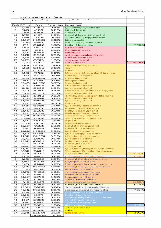
72 González Rivas, Álvaro
Alucha project IV (17/11/2015)
oil from paper sludge from company #2 after treatment
Peak R.Time Area Percentage Component
6 6,364 2126014 0,485% 3,3-dimethyl-cyclohexanol
8 6,843 489522 0,112% 1,6-diol-hexene
9 7,008 929434 0,212% 5-octen-1-ol
16 8,725 240874 0,055% 3-methyl-hepta-1,6-dien-3-ol
17 8,996 233073 0,053% propenylciclopropylmethanol
41 13,567 14725681 3,360% 1,2-benzendiol
46 15,025 5498330 1,255% 3-hydroxi-benzenmethanol
53 17,8 8176153 1,866% 4-ethyl-2-benzendiol 7,398%
1 4,074 3011042 0,687% butanoic acid
4 6,117 83484 0,019% 8-chlorocapric acid
47 15,427 7818354 1,784% Benzoic acid
56 19,742 3131660 0,715% cyclopropanecarboxylicacid
64 28,658 17509933 3,996% 1-hexadecanoic acid
70 31,789 8569174 1,955% octadecanoic acid
73 36,217 3902857 0,891% diphenolic acid 10,046%
3 4,634 6489961 1,481% 1,4-dimethyl-pyrazole
10 7,633 9314617 2,125% Furan
12 8,107 11452822 2,613% Phenol
15 8,583 757252 0,173% 2,5-dihydro-3,5-dimethyl-2-furanone
20 9,633 2641063 0,603% 3-phenyl-1-propyne
21 9,944 14142084 3,227% 3-methylphenol
23 10,2 1757197 0,401% acetophenone
25 10,475 16111366 3,676% 3-methylphenol
28 11,217 4018475 0,917% 2,6-dimethylphenol
32 12,02 3919968 0,894% 2,3-dimethylphenol
33 12,156 1499122 0,342% hexahydro-2,5-methano-furopyran
34 12,292 14510582 3,311% 2,5-dimethylphenol
35 12,617 1379116 0,315% (1-methylene-2-propenyl)benzene
37 12,775 3310168 0,755% 2,3-dimethylphenol
38 12,913 2845726 0,649% 2,6-dimethylphenol
39 13,1 3854429 0,880% Azulene
40 13,35 6584698 1,503% 2,3-dimethylhidroquinone
42 14,175 3449051 0,787% 4-(1-methylethyl)phenol
44 14,433 2603087 0,594% 2-ethyl-5-methylphenol
48 15,7 15712390 3,585% 2-ethoxy-4-methylphenol
49 16,225 16293771 3,718%
51 17,098 1354600 0,309% 2,3-dimethylhydroquinone
52 17,642 8032920 1,833% byphenil
54 18,364 1577345 0,360%
55 19,187 7063989 1,612% 3-allyl-2-methoxyphenol
57 19,917 7885658 1,799% 4-methyl-1,1'byphenil
59 23,242 24567250 5,606% 1,3-diphenil-propane
60 23,808 9467692 2,160% 2,6-diisopropyl-naphtalene
61 24,642 15419564 3,519% 1,2-diphenilciclopropane
63 25,952 2968002 0,677% 1,3-diphenil-butene
65 28,842 4088918 0,933% 2-phenilnaphtalene
66 29,592 2404585 0,549% 4-methylbenzene
69 31,617 5999704 1,369% p-terphenyl
71 32,017 5590841 1,276% 4,4'-(1-methylethyldiene)bis-phenol
72 32,642 3076111 0,702% 2-isopropyl-10-methylphenantrene
74 37,125 2466160 0,563% diisooctilpthalate 55,817%
7 6,443 1638471 0,374% 3,7-dimethyl-2,6-nonadienal 0,374%
5 6,223 2612083 0,596% 2-methyl-2-cyclopenten-1-one
11 8,017 944779 0,216%
14 8,483 1224742 0,279% 2,3-dimethyl-2-cyclopenten-1-one
19 9,285 26247523 5,989% 3-methyl-1,2-cyclopentanedione
22 10,525 1482266 0,338%
26 10,792 4948922 1,129% trymethylcyclopentenone
27 11,125 2489875 0,568%
30 11,567 6267740 1,430%
36 12,7 2709913 0,618%
75 47,433 1591875 0,363% 11,528%
18 9,048 942806 0,215% 2-methyl-2,3-divinyloxirane 0,215%
58 22,033 3096568 0,707% chloroacetic acid hexadecil ester
76 49,542 27859485 6,357% octadecanoic acid ethenyl ester 7,064%
13 8,358 1294466 0,295% 2,3-dimethyl-2,4-hexadiene
24 10,358 805570 0,184% 2-ethyl-2-pentenal
31 11,853 1438637 0,328% (1-methylethyldiene)cyclohexane
43 14,27 5920009 1,351%
45 14,942 2480821 0,566% trymethylcyclopropane
62 25,767 5396324 1,231% 10-heneicosene 3,956%
2 4,226 73031 0,017% 6-deoxy-L-manose
29 11,402 4194381 0,957% Maltol
67 29,825 11520403 2,629% cyclooctasulfur 3,603%
438236559 100,00%
dihydromethyl-indanone
7-methyl-indanone
1-cyclopentene-3-one
2-cyclopenten-1-one
3-ethenylcyclohexanone
dimethyl-decadienone
dipentanedecyl ketone
trimethylcyclohexene
2-cyclopenten-1-one

Phenolic fraction recovery from pyrolysis oil obtained from paper sludge 73
NAME: Alucha project V (9/12/2015)
oil from paper sludge from company #3 before treatment
Peak R.Time Area Percentage Component
4 4.645 3472437 1,251% 1,2-ciclopentanediol
6 6.082 6420089 2,312% 2-furanmethanol
7 6.247 679915 0,245% 3-tertbutyl-4-methoxycyclohexanol
12 8.072 1605611 0,578% Hex-3-ene-1,6-diol
20 10.333 393025 0,142% 2-Nonen-1-ol
24 11.718 538852 0,194% 4,4-dimethyl-cyclohex-2-en-1-ol
26 12.521 339629 0,122% cyclodecanol 4,844% 3,876%
13 8.298 261818 0,094% cyclopentaneundecanoic acid
14 8.564 322388 0,116% 2-Nonenoic acid 0,210% 0,168%
8 6.385 2701337 0,973% 3-butylhydro-2(3H)-furanone
9 6.860 8217885 2,960% Styrene
11 7.705 3782416 1,362% Tetrahydropyran
17 9.180 2843291 1,024% 3,3-dimethyl-(3H)-Indazole
25 12.052 247157 0,089% 2(1H)-Naphtalenone
29 13.637 710181 0,256% 3-methyl-1H-indene
34 17.427 4187014 1,508% 2-ethoxy-4-methylphenol 8,173% 6,538%
23 11.177 2244497 0,808% cyclohexanecarboxaldehyde
27 12.901 1897453 0,683% 3,3-dimethyl-5-oxo-cyclohexacarboxaldehyde
33 16.141 2720186 0,980% 5-Hydroxymethyl-2-furancarboxaldehyde
35 19.050 488308 0,176% 2-formyl-3-methyl-cyclopentaneacetaldehyde 2,648% 2,118%
2 4.272 17999768 6,483%
10 7.316 8381050 3,019% 2-methyl-2-cyclopenten-1-one
18 9.680 405430 0,146%
19 9.863 902462 0,325% 2-hydroxyhexadecilbutanone
21 10.556 21894895 7,886% 3-methyl-1,2-pentanedione
22 10.757 809794 0,292% 18,151% 14,521%
3 4.576 792200 0,285% 1-butoxy-2-methyl-butane
15 8.742 473087 0,170% 1-Isobutoxy-2-ethylhexane
16 8.965 2054170 0,740% 2-methyl-2,3-divinyloxirane
31 15.591 10546999 3,799% (1,1-dimethylbutyl)oxirane 4,995% 3,996%
28 13.427 670632 0,242% 4-pentadecyl ester valiric acid 0,242% 0,193%
38 25.029 2383473 0,859% 1,1'-(1,3-propanediyl)bis-benzene 0,859% 0,687%
1 4.054 3744 0,001% 3-O-Benzyl-d-glucose
5 4.837 324742 0,117% L-mannose
30 15.121 21468160 7,733% 2-methoxy-1,3-benzodioxale
32 15.895 6749562 2,431% Anhydro-D-annosan
36 22.776 1,35E+08 48,796% D-Allose
37 24.618 2222284 0,800% 1,5-Anhydro-D-mannitol 59,879% 47,903%
2,78E+08 100%
water
content of
20%
1-hydroxy-2-butanone
Iridomyrmelin
2(1H)-pyrimidinone

74 González Rivas, Álvaro
NAME:Alucha project VI (9/12/2015)
oil from paper sludge from company #3 after treatment
Peak R.Time Area Percentage Component
11 8.361 6494718 0,848% 2-(benzylamino)-ethanol
16 9.418 585221 0,076% 1-(2-methylphenyl)ethanol
21 10.327 4979361 0,650% 2-ethyl-1-hexanol
41 15.325 3953037 0,516% 1-methyl-tetrahidronaphtalene-1-ol
44 17.245 5346828 0,698% 4-hydroxy-benzenemethanol
47 19.318 47710375 6,231% 1-phenyl-1,3-cyclohexadien-5-ol 9,021%
2 4.620 2189266 0,286% 5-hexanoic acid
4 6.439 115719 0,015% 3-chloropropanoic acid
19 9.814 1186071 0,155% Valeric acid
55 30.155 33142126 4,328% N-hexadecanoic acid
58 32.965 52581216 6,867% 6-octadecanoic acid
59 33.312 18434884 2,408% Eicosanoic acid
63 36.098 3574731 0,467% phenanthrene carboxylic acid 14,526%
14 9.171 50323943 6,572% Methylstyrene
15 9.270 5132926 0,670% Phenol
25 10.918 14864949 1,941% Indene
26 11.071 2202501 0,288% Hexahydronaphtalene
27 11.196 17362889 2,268% 3-methylphenol
29 11.796 29564902 3,861% 2-methylphenol
30 12.064 2496852 0,326% 2(3H)benzofuranone
31 12.603 3988625 0,521% 2,6-dimethylphenol
34 13.634 31677140 4,137% tetrahydronaphtalene
35 13.839 3361148 0,439% 3-methyl-1H-indene
36 13.947 3187996 0,416% Naphtalene
37 14.093 7637992 0,998% 1,4-dihydronaphtalene
39 14.694 19620323 2,562% Azulene
42 15.802 4224465 0,552% 3,4,5-trimethylphenol
48 21.608 31515281 4,116% 4-methyl-,11'-byphenil
60 33.662 18208834 2,378% p-terphenyl
61 34.560 8444074 1,103% phenanthrene
62 35.027 4717303 0,616% triphenyl-2-decanol 33,765%
13 8.904 15262938 1,993% 5-methyl-2-furancarboxaldehyde 1,993%
1 4.168 1649265 0,215% 1-phenyl-2-butanone
7 7.282 9255530 1,209% 2-methyl-2-cyclopentenen1-one
23 10.539 10784762 1,409% 3-methyl-1,2-cyclopentanedione
24 10.743 10899368 1,423% 2,3-dimethyl-2-cyclopenten-1-one
28 11.286 1816329 0,237% Benzofuranone
32 12.864 3283335 0,429% 3-ethyl-2-hydroxy-2-cyclopenten-1-one
33 13.123 3432887 0,448% 3-ethenylcyclohexanone
65 49.000 17353560 2,266% 16-Hentriacontanone 7,637%
9 8.044 4665801 0,609% 1-methyl-4-methylene-cyclohexane
18 9.663 3332037 0,435% 2-methyl-2,3-divinyloxirane
20 10.188 3801520 0,496% 1,2,4-tris(methylene)cyclohexane
50 23.258 5376543 0,702% 3-octadecane
52 24.924 63875966 8,342% 1,3-diphenylpropane
54 26.568 10546626 1,377% 1,2-diphenilcyclopropane
64 40.966 3056370 0,399% 2,3-dimethylnonadecane 12,362%
57 32.260 1656725 0,216% 9-octadecanoic acid methyl ester 0,216%
3 6.250 3050752 0,398% 1,3-dimethylbenzene
5 6.619 817907 0,107% 2-methyl-2,3-hexadiene
6 6.832 27494227 3,591% Benzocyclobutene
8 7.568 12965667 1,693% (1-methyl)benzene
10 8.191 2176376 0,284% 1-propenylbenzene
17 9.536 2245147 0,293% 1-ethenyl-2-methylbenzene
22 10.406 4697411 0,613% 2-propenylbenzene
38 14.535 751682 0,098% trimethyl-cyclohexane
43 16.799 9441423 1,233% (1-mmethylenbut-2-enyl)benzene
45 17.762 27193667 3,552% benzocycloheptatriene
46 18.118 3588997 0,469% 2-cyclohexen-1-yl-benzne
51 24.485 4250939 0,555% 7-phenylbicyclo(3,2,1)octa-2,6-diene
53 26.169 29339069 3,832% 2,6-diisopropylnapthalene
56 30.933 18729528 2,446% 1-(4-methylphenyl)-4-phenylbuta-1,3-diene 19,165%
12 8.555 2441129 0,319% 2-methyl-3-methylene-1-hepten-5-yne
40 14.971 3603117 0,471% 2-methoxy-1,3-benzodioxole
49 22.141 4023722 0,526% 3,4-altrosan 1,315%
765686018 100%

Phenolic fraction recovery from pyrolysis oil obtained from paper sludge 75
NAME: Alucha project VII (14/12/2015)
aqueous phase of oil from paper sludge from company #3 after treatment
Peak R.Time Area Percentage Component
7 6,385 725541 0,337% cyclohexanetetrol
8 6,92 386698 0,180% cyclopentanetetrol
10 7,366 1294290 0,602% 1,2,4-cyclopentanetriol
12 7,7 3934140 1,830% 2-(3-Methylguanidino)ethanol
14 9,018 1438047 0,669% 5-octen-1-ol
21 13,507 2104366 0,979% 2-ethyl-2-hexen-1-ol
23 15,541 10270960 4,777% 2,7-dimethyl-4,5-octanediol 9,374% 7,499%
11 7,573 257858 0,120% 7-oxo-octanoicacid
13 8,081 472969 0,220% 2-nonenoic acid
15 9,384 4642865 2,160% 2-chlorohexanoic acid
18 11,229 920378 0,428% octyl ester pentanoic acid
19 11,694 637319 0,296% 4,4-dimethylcyclo-hex-2-en-2-ol 3,224% 2,579%
27 17,501 4872940 2,267% 2-ethoxy-4-methylphenol 2,267% 1,813%
17 11,151 663684 0,309% 3,3-dimethyl-5-oxo-cyclohexane carboxaldehyde 0,309% 0,247%
1 4,274 11414896 5,309% 1-Hydroxy-2-butanone
16 10,51 19007619 8,841% 3-methylcyclopentanedione
20 12,51 308454 0,143% 6-hydroxyhexahydropenta(b)furan-2-one
24 15,772 247430 0,115% 2-hydroxymethylcyclohexanone 14,409% 11,527%
2 4,557 1160619 0,540% 1-butoxy-2-methylbutane
6 6,254 151311 0,070% 1,3-dimethoxyciclopentane
22 15,1 15304273 7,119% 2-methoxy-1,3-benzodioxole 7,729% 6,183%
26 16,238 2408926 1,120% 3-ethyl-4,4-dimethyl-2-pentene 0 0
28 17,714 479845 0,223% hexahydro-3-methylene-2(3H)benzofuranone 1,344% 1,075%
3 4,797 2027709 0,943% 6-deoxy-L-mannose
4 4,85 991762 0,461% Digitoxose
5 6,136 2473263 1,150% 3,4-Anhydrogalactosan
9 7,194 245473 0,114% 2-Deoxy-D-galactose
25 15,845 6831116 3,177% Anhydro-D-mannosan
29 22,665 116798525 54,327% D-Allose
30 24,601 2519458 1,172% Heptose 61,345% 49,076%
214992734 100%
water
content of
20%

76 González Rivas, Álvaro
NAME: Alucha project VIII (17/12/2015)
oil from paper sludge from company #3: Organic fraction 1C
Peak R.Time Area Percentage Component
1 6 14602162 17,93% Ethylbenzene
2 6,869 15261795 18,74% Styrene
3 7,567 997278 1,22% 2-phenyloxetane
4 11,229 3423103 4,20% 3-cyclohexenil-1-phenyl-propane
5 11,328 6933512 8,52% 6-heptinyl-benzene
6 11,585 1716659 2,11% 8-phenyl-3-octen-2-one
7 11,871 495375 0,61% methyl ester 2,5-octadecanoic acid
8 12,015 4277981 5,25% ?
9 12,766 2450578 3,01% stigmastan-3,5-diene
10 13,466 2061149 2,53% 1-chlorooctadecane
11 15,06 7859024 9,65% 16-Hentriacontanone
12 16,341 673868 0,83% ?
13 16,816 1307119 1,61% 2,3,5,8-tetramethyldecane
14 18,691 1719526 2,11% Palmitic acid vinyl ester
15 20,626 1034418 1,27% 1-chloroheptacosane
16 22,525 15953078 19,59% ethyl ester octadecanoic acid
17 24,633 659076 0,81% behenylchloride
81425701 100,00%
NAME: Alucha project IX (17/12/2015)
oil from paper sludge from company #3: Organic fraction 2C
Peak R.Time Area Percentage Component
1 6 23089262 13,65% Ethylbenzene
2 6,933 20332980 12,02% Styrene
3 7,567 2299494 1,36% Benzamethylamino
4 10,703 567358 0,34% Behenylchloride
5 11,3 14801144 8,75% 4-methylene-cyclooctane
6 11,966 6760325 4,00% 1-chlorooctadecane
7 12,75 7617278 4,50% ?
8 13,454 7602877 4,50% phenylmethyl ester octoacetic acid
9 15,017 18914915 11,19% 16-hemtriacontanone
10 16,798 3305578 1,95% 1-chlorooctadecane
11 16,644 32626809 19,30% palmitic acid vinyl ester
12 20,607 1840882 1,09% Behenylchloride
13 22,64 26299351 15,55% ethenyl ester octadecanoic acid
14 24,719 1117399 0,66% ?
15 25,886 841536 0,50% ?
16 26,885 1074292 0,64% ?
169091480 100,00%

Phenolic fraction recovery from pyrolysis oil obtained from paper sludge 77
NAME: Alucha project X (18/12/2015)
oil from paper sludge from company #3: Aqueous fraction 1C
Peak R.Time Area Percentage Component
1 4,335 4530022 15,00% 1-Hexen-3-ol
2 4,63 2276053 7,54% 4-methyl-pentanoic acid
3 6,149 5078637 16,82% 2-Furanmethanol
4 8,073 360771 1,19% 3-Decen-1-ol
5 10,493 2820248 9,34% Cyclooctanone
6 10,742 340731 1,13% Decanol
7 10,491 1611770 5,34% 2-(hydroxymethyl)-Cyclohexanone
8 22,106 13172962 43,63% D-Allose
30191194 100,00%
NAME: Alucha project XI (18/12/2015)
oil from paper sludge from company #3: Aqueous fraction 2C
Peak R.Time Area Percentage Component
1 4,342 6396351 12,90% 1-Hydroxy-2-butanone
2 4,63 2960787 5,97% 3,4-Altrosann
3 6,13 2130016 4,30% 2-Furanmethanol
4 6,864 4460352 9,00% Styrene
5 7,715 656721 1,32% 2-Nonenoic acid
6 8,062 799037 1,61% 3-Decen-1-ol
7 10,491 4223078 8,52% cyclooctane
8 10,74 761170 1,54% Decanal
9 11,225 1267703 2,56% 3-none-1-ol
10 15,502 2403805 4,85% (1,1-dimethyl)oxirane
11 15,826 1547974 3,12% Anhydro-D-Mannosan
12 22,23 21958148 44,30% D-Allose
49565142 100,00%

