trek® tab belt drive - bike- · pdf filemaintenance 2 2. periodic maintenance for the...
TRANSCRIPT

i
Trek® TAB Belt Drive Supplement to owner’s manual
Important: Keep for Future ReferenceThis supplement gives instructions on the use and maintenance of the TAB (Trek Auto Belt) belt drive system on your Trek bicycle. It is a supplement to the Trek Bicycle Owner’s Manual.
This manual is written for the owner, but requires some mechanical experience. Some maintenance should only be performed by the dealer, and this manual tells you when that is.
Check for updatesFor revisions to this manual and the most current information, check our web site at www.bontrager.com
Meaning of Safety Signs and LanguageIn this manual the Safety Alert symbol, a triangle with an exclamation mark, shows a hazardous situation which, if not avoided, could cause injury.
About TAB Belt DriveIn the Trek Belt Drive system, the traditional bicycle chain (with its metal links and toothed sprockets) is replaced by a flexible, rubber-based belt (and its special self-cleaning sprockets). This system is quiet and easy to maintain. In particular, it does not require any lubrication, and this also means it is a clean system.
Be SafeA bicycle can be fun when used for transportation, recreation, exercise, or competition. But a bicycle can also be dangerous, especially if you try to ride beyond the limits of your bicycle or the limits of your ability. This manual does not provide all the safety information needed for a person riding a bicycle. Please read the safety information in your bicycle owner’s manual before using this seatpost. If you do not have a bicycle owner’s manual, visit www.bike-manual.com.
If after reading this manual you have additional questions, contact your dealer or the technical support team:
Trek Attn: Customer Service 801 W. Madison Street Waterloo, Wisconsin 53594 920.478.4678 www.trekbicycles.com
PN ??????
Table of ContentsIntroduction .................................................11. Names of Parts .........................................12. Periodic Maintenance ..............................23. Wheel Installation ....................................34. Belt Tension Adjustment ..........................55. Centering Tension Pulley .........................66. Sprocket Installation and Removal .......... 77. Belt Installation ......................................10Warranty ....................................................11
® Trek is a registered trademark of the Trek Bicycle Corporation© Copyright Trek Bicycles 2015 L
‘CAUTION’ indicates the possibility of mild or moderate injury. ‘WARNING’ indicates the possibility of serious injury or death.
1
Trek Belt Drive Manual Supplement
1 Parts of the System
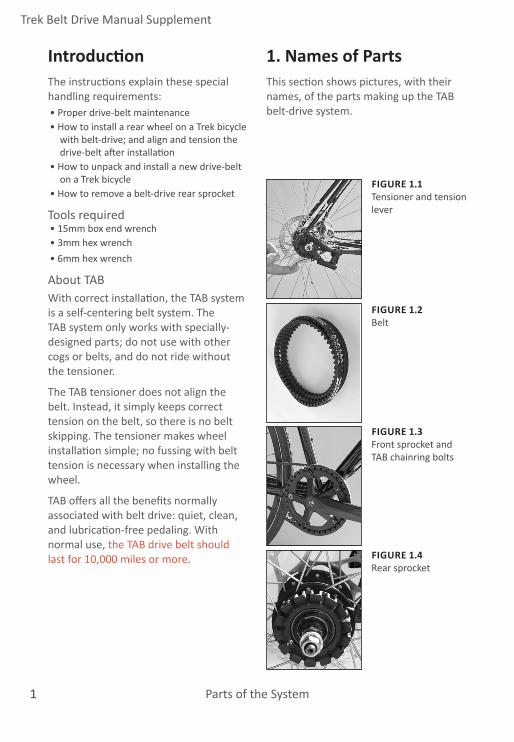
FIGURE 1.2Belt
1. Names of PartsThis section shows pictures, with their names, of the parts making up the TAB belt-drive system.
FIGURE 1.3Front sprocket and TAB chainring bolts
FIGURE 1.4Rear sprocket
FIGURE 1.1Tensioner and tension lever
IntroductionThe instructions explain these special handling requirements:• Proper drive-belt maintenance• How to install a rear wheel on a Trek bicycle
with belt-drive; and align and tension the drive-belt after installation
• How to unpack and install a new drive-belt on a Trek bicycle
• How to remove a belt-drive rear sprocket
Tools required• 15mm box end wrench• 3mm hex wrench• 6mm hex wrench
About TABWith correct installation, the TAB system is a self-centering belt system. The TAB system only works with specially-designed parts; do not use with other cogs or belts, and do not ride without the tensioner.
The TAB tensioner does not align the belt. Instead, it simply keeps correct tension on the belt, so there is no belt skipping. The tensioner makes wheel installation simple; no fussing with belt tension is necessary when installing the wheel.
TAB offers all the benefits normally associated with belt drive: quiet, clean, and lubrication-free pedaling. With normal use, the TAB drive belt should last for 10,000 miles or more.

22Maintenance
2. Periodic MaintenanceFor the smoothest riding and the longest life, check your TAB belt drive system regularly according to the following schedule.
InspectionOnce each month inspect the drive belt. There should be no frayed areas or chipped rubber. If either of these are detected, replace the drive belt.
Once each month, check the belt tension?
Once each month, check the front and rear sprockets. Look for damaged or deformed teeth, or areas of unusual wear. If any damage is detected, replace the sprocket.
Once each month, check the tensioner. Make sure that the tensioner can move through its range of motion while under tension (HOW?). Release tension from the belt and spin the pulley. It should spin freely with no friction, grittiness, or side play. If the pulley does not spin properly, replace it.
Also check that the pulley is centered on the belt. Hold the rear wheel off the ground and slowly rotate the pedals. The pulley should be visually centered on the belt. If the pulley is not centered, follow the instructions to center it.
AdjustmentAdjustment of the pulley (centering) is covered on page 5.
The tension on the drive belt is adjustable. See Section 4, Belt Tension Adjustment.
The chain line can be adjusted. This is normally done during installation. See that section for instructions.
CleaningThe TAB drive belt is not metal, so it can react to a variety of chemicals. Avoid all cleaning agents except water and mild dish soap. To help clean the teeth of the belt or sprockets, use a soft nylon-bristle brush.
WARNING: Incorrect mechanical work can make your bicycle unsafe. Read the Trek Bicycle Owner’s Manual for more information, or consult your dealer.

3
Trek Belt Drive Manual Supplement
Wheel Installation
FIGURE 3.2Inserting axle into dropout
FIGURE 3.4Assembly with axle nut installed
FIGURE 3.3Orientation of toothed washer
FIGURE 3.1Moving tension lever to low-tension position
3. Wheel Installation: Single-speed hubTools required• 15mm box end wrench
To install a rear wheel1. Move the tension lever to the low-
tension position (Figure 3.1).
2. Place the belt on the rear sprocket and insert the axle into the dropouts (Figure 3.2). Make sure the non-drive washer and bolt are correctly placed. Place the toothed washer on the axle with the tooth in the slot formed by the dropout and the tensioner (Figure 3.3).You may have to rotate the axle in the dropout to achieve this position.
3. Attach the wheel. Thread the axle nut onto the axle (Figure 3.4). Align the wheel and tighten the axle nuts to 27.1-33.9 Nm (240-300 lb•in).
4. Move the tension lever to the ride position (Figure 3.5).
FIGURE 3.5Tension lever engaged

4Wheel Installation
Wheel Installation: Internally-geared hubA hub brake such as a drum brake, or internal brake, usually requires multiple frame attachment and multiple adjustments. Due to this complexity and importance to your safety, we highly recommend that any adjustment of a hub brake, or removal of the wheel from the frame, only be done by your dealer.
Tools required• 15mm box end wrench
To install a rear wheel1. Move the tension lever to the low-
tension position (Figure 3.1).
2. Place the belt on the rear sprocket and insert the axle into the dropouts (Figure 3.2). Make sure the non-drive washer and bolt are correctly placed. Place the toothed washer on the axle with the tooth in the slot formed by the dropout and the tensioner (Figure 3.3).You may have to rotate the axle in the dropout to achieve this position.
3. Attach the wheel. Thread the axle nut onto the axle (Figure 3.4). Align the wheel and tighten the axle nuts to 27.1-33.9 Nm (240-300 lb•in).
4. Align the bell crank with the axle nut, and press onto the nut (Figure 3.6).
5. Tighten the bell crank fixing bolt (Figure 3.7).
6. Move the tension lever to the ride position (Figure 3.5).
7. If needed, adjust the shifting.
FIGURE 3.5Bell crank and axle nut
FIGURE 3.7Bell crank fixing bolt
Bell crank
Axle nut

5
Trek Belt Drive Manual Supplement
Maintenance
FIGURE 4.2Adjusting tension
FIGURE 4.1Tension adjustment screw
4. Belt Tension AdjustmentThe TAB system has a wide range of acceptable tension. Excessive tension will increase drag on the system, making it harder to pedal. Lack of tension will allow the belt to slip. In other words, as long a the belt is not slipping and pedal resistance is low, the tension is acceptable.
Tools required• 6mm hex wrench
To change drive belt tension1. Make sure the tension lever is
engaged (Figure 4.2).
2. Locate the tension adjustment screw (Figure 4.1) and rotate it (Figure 4.3): clockwise to increase tension, counter-clockwise to decrease tension.
3. Pedal the system by hand to feel for pedal resistance. It should be low.
FIGURE 4.2Tension lever engaged

6Maintenance
FIGURE 5.3Tightening centering clamp screw
FIGURE 5.1Centering screw
5. Centering Tension PulleyIf the sprocket spacing is correct, the belt will center itself automatically. If there is excessive noise, the tension pulley may need adjustment.
Tools required• 3mm hex wrench
To center the tension pulley1. Make sure the tension lever is
engaged (Figure 5.2).
2. Loosen the centering clamp screw.
3. Move the centering pulley as needed.
4. Tighten the centering clamp screw to 6 Nm.
5. Gently pedal the system by hand while inspecting the centering of the belt. Re-adjust as necessary by following steps 1-4.
FIGURE 5.2Tension lever engaged

7
Trek Belt Drive Manual Supplement
Maintenance
FIGURE 6.2Gap between belt and straight edge
6. Sprocket Installation and RemovalDue to the long expected life of the Trek TAB sprockets, you should only have to replace sprockets if there is accidental damage. However, sprocket installation affects chain line, so the installation instructions are given here.
Tools required• Cassette lockring tool• Small, slot-type screwdriver• Drive-sprocket strap wrench
To check the chain line1. Engage the tension lever (Figure 6.1).
2. Place a straight edge against the chainring (Figure 6.2) with the 12” (30cm) mark directly above the center of the bottom bracket.
3. Measure the gap between the end of the straight edge and the belt. • Acceptable gap is less than 3mm.
To remove the rear sprocket (driver type)1. Remove the rear wheel from the
frame.
2. With a small slot-type screwdriver, pry the snap ring out of its groove in the driver (Figure 6.3).
3. Slide the sprocket off the driver.
FIGURE 6.3Pry the snap ring out of the groove in driver
FIGURE 6.1Tension lever engaged

8Maintenance
To remove the rear sprocket (cassette type)NOTICE: When removing the rear sprocket, never use the drive-belt as a tool (Figure 6.4). Using the drive-belt as a tool puts bends in it that can damage it and cause it to fail.
1. Remove the wheel from the frame.
2. Wrap the drive-sprocket strap wrench around the sprocket.
3. With a cassette lockring tool (Figure 6.5), remove the lockring.
4. Slide the sprocket off the splines of the hub.
To install the rear sprocket (either type)1. Determine the correct orientation of
the rear sprocket:
• For an internal gear hub, the side of the sprocket with more metal exposed goes to the outside (Figure 6.6).
• For a splined hub, the sprocket can face either way, which allows adjustment of the chainline.
2. Slide the sprocket onto the driver. Note: With the cassette-type rear sprocket, spacers are required to fill the space on the freehub body (Figure 6.7). You can place these spacers on either side of the sprocket to adjust the chain line.
3. Fasten the lockring or snap ring.
4. Install the wheel, and check the chain line (see page 5).
FIGURE 6.4Do not use TAB belt as a tool
FIGURE 6.5Drive-sprocket strap wrench and cassette lockring tool
FIGURE 6.6Sides of sprocket for internal-geared hub
FIGURE 6.7Spacers on cassette driver
Inside
Outside

9
Trek Belt Drive Manual Supplement
Maintenance
To remove the front sprocketIt may be helpful later if you note the orientation before removal. The front sprocket has four possible orientations, each creating a different chain line:• Inside the crankarm spider • 6mm offset • 8mm offset• Outside the crankarm spider • 2mm offset • 4mm offset
1. Remove the chainring bolts (Figure 6.8) and guide the sprocket off the crankarm.
To install the front sprocket1. Select the desired front sprocket
location and orientation (Figure 6.9).
2. Install the TAB chainring bolts. Note: Do not use other chainring bolts. The larger heads of the TAB bolts are necessary to correctly fit the holes in the chainring. Undersized bolts will not properly support the chainring, and could break.
3. Tighten the bolts to 12-14 Nm (106-124 lb•in).
4. Install the TAB belt and check the chain line (see page 5).
FIGURE 6.8Chainring bolts
FIGURE 6.9Four front sprocket positions offer chain line options

10Maintenance
7. Belt InstallationNote: Although the TAB belt is quite flexible, it should still be handled with care. Avoid crimping it or creating a sharp bend.
To put the drive-belt on the frame1. Remove the seatstay bolt (Figure 7.1).
2. Gently spread the stays and insert the drive-belt through the opening (Figure 7.2).
3. Hang the drive-belt over the front sprocket (Figure 7.3).
4. Replace the dropout.
5. Follow the instructions for your type of Wheel Installation.
FIGURE 7.1Seatstay bolt
FIGURE 7.2Stays spread to open a gap for belt
FIGURE 7.3TAB belt on front sprocket

11
Trek Belt Drive Manual Supplement
Additional Information
For further information or additional assistanceThe Trek Owner’s Manual provides additional information for belt-drive bicycles. If, after reading both this instruction booklet and the owner’s manual, you have additional questions, contact the Trek technical support team at www.trekbikes.com.
WarrantyThe TAB system is covered by a warranty different from the remainder of the bicycle. For the general bicycle warranty, see www.trekbikes.com/warranty
The TAB system is covered against defects in materials and workmanship for a period of 1 (one) year.