tremec - mg xpower sv · pdf fileinspection list 14 turret control ... tremec parts according...
TRANSCRIPT

TREMECM.R.
INDEXNOTES, CAUTIONS WARNINGS&

As you read through the procedures, you will come across NOTES,CAUTIONS, and WARNINGS. Each one is there for a specific purpose.NOTES give you added information that will help you to complete aparticular procedure. CAUTIONS are given to prevent you from makingan error that could damage the vehicle. WARNINGS remind you to beespecially careful in those areas where carelessness can causepersonal injury. The following list contains some general WARNINGthat you should follow when you work on a vehicle.
Always wear safety glasses for eye protection.
Use safety stands whenever a procedure requires you to be under thevehicle with the vehicle jacked up.
Be sure that the ignition switch is always in the OFF position, unlessotherwise required by the procedure.
Set the parking brake when working on the vehicle. It should be inREVERSE (engine OFF) or NEUTRAL (engine ON) unless instructedotherwise for a specific operation. Place wood blocks (4”X4” or larger)to the front and rear surfaces of the tires to provide further restraintfrom inadvertent vehicle movement.
Operate the engine only in a well-ventilated area to avoid the dangerof carbon monoxide.
Keep yourself and your clothing away from the moving parts, whenthe engine is running, especially the fanand drive belts.
To prevent serious burns, avoid contact with hot metal parts such asthe radiator, exhaust manifold tail pipe, catalytic converter and muffler.Do not smoke while working on the vehicle.
To avoid injury, always remove rings, watches, loose hanging jewelry,and loose clothing before beginning to work on a vehicle. Tie long hairsecurely behind the head.
Keep hands and other objects clear of the radiator fan blades, Electriccooling fans can start to operate at any time by an increase in underhood temperatures, even though the ignition is in the OFF position.Therefore, care should be taken to ensure that the electric cooling fanis completely disconnected when working under the hood.
Disconnect the negative battery ground cable before using any electricwelding equipment.
Appropriate service methodsand proper repair procedure areessential for the safe, reliableoperation of all motorvehicles as well as the personalsafety of the individual doingthe work.
This Manual provides generaldirections foraccomplishing service andrepair work with tested,effective techniques.
Following them will help assurereliability.
There are numerous variationsin procedures, techniques,tools and parts for servicingvehicles, as well as in the skillof the individual doing the work.
This Manual cannot possiblyanticipate all such variationsand provide advice orcautions as to each.
Accordingly, anyone whodeparts from the instructionsprovided in this Manual mustfirst establish that hecompromises neither hispersonal safety nor the vehicleintegrity by his choice ofmethods, tools orparts.
NOTES, CAUTIONS & WARNINGS
TREMECM.R.

3
Introduction 4
Explosive view 5
Transmission Parts 6
Specifications 7
Lubrication 8
General Information 9
Torque Recomendations 10
Axial Clearances 12
Preventive Maintenance 12
Precautions 13
Inspection List 14
Turret Control Disassembly 15
Control Parts Group Disassembly 22
Primary Gear Parts Group Disassembly 24
Secondary Group Disassembly 30
Input Shaft Disassembly 31
Case Parts Group Input Shaft Disassembly 33
Extension Disassembly 36
Reassembly Reverse Gear 38
Troubleshooting Guide 57
Tools 60
CONTENTS

TR-3650
4
INTRODUCTION
This manual is designed to provide detailed informationnecessary to service and repair the TREMEC 3650transmission listed on the cover. As outlined in the Table ofContents, the manual is divided into 4 main sections:
a) Technical Information and reference
b) Disassembly and reassembly of the transmission
c) Troubleshooting guide
d) Tools required
The format of the manual is designed to be followed in itsentirety if complete disassembly and reassembly of thetransmission is necessary. But if only one component of thetransmission needs to be repaired, see the Table of Con-tents for the page numbers showing that component. Forexample, if you need to work on the Shifting Controls, youwill find instructions for removal, disassembly, and reassem-bly on page into. Service manuals, Illustrated part list,drivers instructions, and other forms service information fortheses and other TREMEC transmission are available uponrequest.On any repair or parts replacement, always use “original”TREMEC parts according to the corresponding “Servicepart Catalog”.The use “non original” parts may endanger the operationand performance of the transmission.
TRANSMISIONES Y EQUIPOS MECANICOS, S.A. DE C.V.DOES NOT GUARANTEE service parts or failures resultedfor a misuse or not being provided by an authorizedTREMEC distributor.A product literature order from, service bulletins (detailinginformation on product improvements), repair procedures,and other service related subjects can be obtained bywriting to the following address:
PLANT AND GENERAL OFFICES:
TRANSMISIONES Y EQUIPOS MECANICOS, S.A. DE C.V.Av. 5 de Febrero No. 2115C.P. 76120, Querétaro, Qro.MEXICOTR-3650
TREMECDesign
x10 Capacity nominal lbs-ft
NOMENCLATURE:
Letter designations Number designations
Design Level
Forward speeds

5
EX
PL
OS
IV
E V
IE
W
71
143
129
5452
48
57
56
65
67
58
130
59
67
6
49
63
129
50
115
113
128
112
132
113
115
113
82
5 4 5
105
113
110
81
60 84 127
127
126
79
114
41
116
66
150
135
136
145
118
119
120
121
122
123
46
11
12
13
161514 17
1893
70 69
46
429091
106
68
19
20
21
102
43
44
18
146
21
20
19
106
73
46
3914
4
138
106
40
102
68
14
99
142
125
147
148
24 25 26 27
28
151
35
141
102
30
38
30
85
140
18
46
86
139
87
112
129
114
129
133
5553
10
64
80
134
9511
1
105
113 33
29
22
72
92
39
23
89
45
1894 137
37
36
103
100
89
94
89
108
107
117
83
97
109
98
2
104
104
104
104
104
104
129
124
129
104
5112
9
113
6260
61
149
8
40
106
31
32
31
7875 76 77
74
29
34
45
88 96
1
13147
6
104
10
7
33
9
138
141
23

TR-3650
6
TRANSMISSION TR-3650 PARTS
1 1 MAGNET2 1 ROLL PIN3 8 ROLL PIN4 1 SNAP RING SPEEDOMETER5 1 TAG IDENTIFICATION6 1 CENTER INTERLOCK PIN7 2 SHIFTER INTERLOCK8 1 BEARING ROLLER CUP *9 2 ROLLER BEARING SELECTOR ARM10 1 SPRING INHIBITOR11 14 BOLT METRIC HEX WASHER HD12 2 NYLON STOP13 1 BEARING INPUT SHAFT POCKET14 1 THRUST BEARING ASS’Y15 1 THRUST WASHER SHAFT PILOTED16 AR SNAP RING 2.30+/-0.05 MM AS REQU.17 AR SNAP RING 2.40+/-0.05 MM AS REQU.18 AR SNAP RING 2.50+/-0.05 MM AS REQU.19 AR SNAP RING 2.60+/-0.05 MM AS REQU.20 12 SPRING SYNCHRONIZER21 2 1st. & 2nd. INNER RING22 2 BLOCKER RING & LINING ASSY 1st. & nd.23 2 1st. & 2nd. BLOCKER RING24 1 SNAP RING HUB SYNCHRO 1st. & 2nd.25 2 SNAP RING TOP INSERT26 1 BEARING CONE & CUP ASS’Y MAIN SHAFT27 1 BEARING CONE*28 AR BEARING SHIM C.S. AS REQUIRED29 AR BEARING SHIM C.S. AS REQUIRED30 AR BEARING SHIM C.S. AS REQUIRED31 AR BEARING SHIM C.S. AS REQUIRED32 1 BEARING CONE & CUP ASS’Y C.S.33 1 CUP BEARING *34 2 ROLLER BEARING GEAR 5th. C.S.35 2 ROLLER BEARING GEAR REV. IDLER36 1 SPACER ROLLER BEARING GEAR REV.37 2 O’RING INHIBITOR38 1 CONE BEARING*39 1 BEARING CONE & CUP ASS’Y REAR C.S.40 1 CUP BEARING REAR C.S.*41 1 CONE BEARING REAR C.S.*42 1 SPACER ROLLER BEARING 5th. C.S.43 1 REVERSE IDLER GEAR44 2 1st. & 2nd. CLUTCH CONE45 1 1st. GEAR SPEED ASS’Y M.S.46 1 1st. GEAR SPEED M.S. *47 2 BUSHING 3rd GEAR & REV.48 1 CLUTCH HOUSING ASS’Y49 1 CLUTCH HOUSING *50 1 TRANSMISSION CASE ASS’Y51 1 TRANSMISSION CASE *52 1 EXTENSION ASS’Y53 1 EXTENSION *54 1 MAIN SHAFT55 1 SPEEDOMETER ROTOR GEAR56 1 OIL SEAL EXTENSION57 1 INPUT SHAFT58 1 3rd GEAR SPEED. M.S.*59 1 2nd. GEAR SPEED. ASS’Y M.S.60 1 2nd. GEAR SPEED. M.S. *61 1 5th. GEAR SPEED. M.S.62 1 SYNCHRONIZER ASS’Y 5th. GEAR C.S.63 1 5th. GEAR C.S.*64 2 5th: & REVERSE SLEEVE *65 1 CLUSTER GEAR66 4 BLOCKER RING 3rd/4th./5th & REVERSE67 1 1st. & 2nd. SHIFT RAIL68 1 3rd & 4 th. SHIFT RAIL69 1 5th. & REV. SHIFT RAIL70 1 5th. FORK SHIFT ASS’Y71 1 5th. FORK SHIFT*72 1 1st. & 2nd. GATE ASS’Y
73 1 1st. & 2nd. GATE *74 1 1st. & 2nd. FORK SHIFT ASS’Y75 1 1st. & 2nd. FORK SHIFT *76 1 3th. & 4th. FORK SHIFT ASS’Y77 1 3th. & 4th. FORK SHIFT *78 1 SELECTOR RAIL79 1 ARM SELECTOR INHIBITOR80 1 SEAT SELECTOR GATE81 4 DETENT PLUG82 3 DETENT83 3 ACTUATING SPRING84 1 REVERSE FORK SHIFT ASS’Y85 1 REVERSE FORK SHIFT *86 1 3rd & 4th. GATE87 1 SHIFTER LEVER ASS’Y88 2 SPACER FONT89 2 THRUST WASHER 3rd GEAR & REV.90 1 3rd & 4th. SYNCHRONIZER ASS’Y91 1 3rd & 4th. SLEEVE *92 1 1st. & 2nd. SYNCHRONIZER ASS’Y93 1 1st. & 2nd. SLEEVE*94 1 SYNCHRONIZER ASS’Y REVERSE GEAR95 1 REVERSE CLUTCH CONE96 1 CLUTCH CONE 5th. SPEED. C.S.97 1 SPRING BASE TURRET98 1 RAIL REVERSE INHIBITOR99 1 INHIBITOR REVERSE100 1 PIN INHIBITOR RETAINER BAR101 1 INTERLOCK SUPPORT102 1 OIL SEAL BEARING RETAINER103 1 WASHER SPRING RETENTION104 1 GEAR REVERSE M.S.105 1 THRUST WASHER 5th. GEAR C.S.106 1 REVERSE SHAFT RAIL107 1 BOLT M8X1.25X60 TORX BOTTON HEAD108 1 REVERSE SUPPORT SHAFT109 1 O’RING110 12 INSERT SYNCHRONIZER111 1 3rd CLUTCH CONE *112 1 3rd GEAR SPEED ASS’Y M.S.113 1 1st. & 2nd. HUB SYNCHRO *114 1 3rd & 4th. HUB SYNCHRO *115 2 5th.. & REV. HUB SYNCHRO *116 3 BALL117 1 BALL SPEEDOMETER118 2 DRAIN PLUG & FILLER PLUG119 1 BREATHER120 4 2nd. & 3rd NEEDLE BEARING ASS’Y121 1 BEARING TAPERED ROLLER CUP122 1 BEARING TAPERED ROLLER CONE123 1 CAP SCREW HEX HEAD SENSOR124 1 SWITCH ASS’Y BACKUP LAMP125 1 TUB RETAINER BEARING*126 4 DOWEL PIN127 1 BUSHING EXTENSION HOUSING128 1 STUD CLUTCH RELEASE LEVER129 1 SEAL OUTPUT SPLINE130 AR BEARING SHIM 0.55 +/- 0.013 MM131 AR BEARING SHIM 0.61 +/- 0.013 MM132 AR BEARING SHIM 0.66 +/- 0.013 MM133 AR BEARING SHIM 0.71 +/- 0.013 MM134 AR BEARING SHIM 0.76 +/- 0.013 MM135 AR BEARING SHIM 0.81 +/- 0.013 MM136 AR BEARING SHIM 0.83 +/- 0.013 MM137 1 SNAP RING138 1 SPRING CENTERING SHIFT CONTROL139 2 BOLT SHOULDER140 14 BOLT METRIC HEX. WASHER HEAD141 4 BOLT METRIC HEX. WASHER HEAD142 9 PAD SHIFT FORK143 1 SENSOR SPEEDOMETER
* SOLD ONLY IN ASS’Y

7
Lengths measured from clutch housing face to cover rear (extension).
Weights include shift bar housing, clutch housing, less shift lever assembly, andclutch parts. For more information on available application, see thetransmission’s illustrated parts list. All weights are approximate.
Oil capacities are approximate, depending on inclination of engine and transmis-sion. Always fill transmission, with proper grade and type of lubricant, to level offiller opening. See LUBRICATION.
SPECIFICATIONS
IMPORTANT
All TREMEC transmissions TR-3650 are identifiedby the model and serial number, and date. Thisinformation is stamped on the transmission identifi-cation tag and affixed to the case.
The transmissions series TR-3650 have five forward speeds and one reverse, of advanced design that offers to you, themost efficent relation of capacity of partorsion-weight, that any other transmissions of 5 speeds within its rank.
NOTES1
2
3
TRANSMISSION MODEL ASSEMBLY DATE
TRANSMISSION NUMBER SERIAL NUMBER
MODEL GEAR RATIOS
1st. 2nd. 3rd. 4th. 5th. REV. OIL CAPACITY
TR-3650-1/2 3.38 2.00 1.32 1.00 0.67 3.38 3800 C.C.
TR-3650-3/4/5 3.38 2.00 1.32 1.00 0.62 3.38 3800 C.C.

TR-3650
8
Proper lubrication procedures are the key to a good allaround maintenance program.If the oil is not doing its job, or if the oil level is ignored, allthe maintenance procedures in the world are not going tokeep the transmission running or assure long transmissionlife.
TREMEC Transmissions are designed so that the internalparts operate in an oil circulating bath by the motion of thegears and shafts.
CHANGE AND INSPECTION OF THE LUBRICANT
Use oil ET-M99 specification.Additives and friction modifiers are not recommended foruse in transmission TR-3650.
PROPER OIL LEVEL
Make sure oil is level with the filler opening. Because youcan reach oil with your finger does not mean oil is at properlevel.
DRAINING OIL
Drain transmission while oil is warm. To drain oil removethe drain plug at case bottom.Clean the drain plug before re-installing.
OIL CHANGE AND REFILLING
Clean case around filler plug and remove plug from caseside. Fill the transmission to the level of the filler opening.
The exact amount of oil depends on the transmissioninclination and model. Do not over fill this causes oil to beforced out of the case and cause a deficients lubrication.when adding oil, types and brands of oil should not bemixed because of possible incompatibility.
LUBRICATION
Thus, all parts are amply lubricated if these procedures areclosely followed:
Maintain oil level. Inspect regularly.
Change oil regularly.
Use the correct grade and type of oil.
Buy from a reputable dealer.
OIL SPECIFICATIONS
MODEL API SPECIFICATION TREMEC OILTRANSMISSION SPECIFICATION CAPACITY
TR-3650 Mobil 1 Synthetic ATF ET-M-99 3.8 Lts.
Dexron III 1300-244-006
1
2
3
4
PROPER OIL LEVEL
IMPROPER OIL LEVEL

9
GENERAL INFORMATIONGENERAL INFORMATIONGENERAL INFORMATIONGENERAL INFORMATIONGENERAL INFORMATION
The TR-3650 transmissions have five forward speeds andone reverse, and are shifted as you would shift anysynchronized transmission manual, following the simple 5speed shift pattern.
Follow the simple 5 speed shift pattern:
The transmission must efficiently transfer the engine’spower, in terms of torque, to the vehicle’s rear wheels.Knowl-edge of what takes place in the transmission duringtorque tranfer is essential when troubleshooting and makingrepairs.
Power ( torque ) from the engine is transferred tothe input shaft and drive gear.
Torque is transferred to the countershaft drive gear.
POWER FLOW
Torque is delivered along the countershaft to allcountershaft gear.
Torque is transferred to “engaged” mainshaft gear.The cross section illustrates 1st speed gear position.
Engaged mainshaft gear internal clutching teethtransfers torque to mainshaft through synchronizerassembly.
Mainshaft transfers torque directly to driveshaft tthrough rear yoke.
1
2
1 3 5
2 4 R
NEUT R A L
3
4
5
6

TR-3650
10
Correct torque application is important to assure longtransmission life. Over or under tightening of fasteners canresult in a loose installation and, in many instances, caneventually cause demage to the transmission. Use a torque
TORQUE RECOMENDATIONS
wrench to obtain recommended torque ratings. Do nottorque capscrews dry. Apply teflon to threads of allcapscrews before in installing definitive.
2

11
TORQUE RECOMMENDATIONS
ITEM QTY DESCRIPTION TORQUE
Nm Lbs/Ft
1 3 DETENT PLUGS 1/2-20 8.2 MM TORX PLUS DRIVE 20-35 15-25
2 14 CLUCTH HOUSING TO TRANSMISSION MAIN CASE BOLT 25-40 19-29M8X1.25 HEX HEAD 13
3 12 EXTENSION TO TRANSMISSION MAIN CASE BOLT 25-40 19-29M8X1.25 HEX HEAD 10 MM
4 4 GEARSHIFT LEVER TO EXTENSION HGS BOLT 25-40 19-29M8 X 1.25 HEX HEAD 10 MM
5 1 REVERSE LIGTH SWITCH M16 X 1.5 HEX HEAD 7/8” 20-35 15-23
6 1 SENSOR SPEEDOMETER BOLT M6 X 1.00 HEX HEAD 10 MM 7-14 5-10
7 1 FILL PLUG 1/2”-14 NPTF SOCKET HEAD 3/8” 20-35 15-25
8 1 DRAIN PLUG 1/2”-14 NPTF SOCKET HEAD 3/8” 20-35 15-25
9 1 REVERSE IDLER GEAR BOLT M8 X 1.25 TORX PLUS 20-35 15-25
10 1 STUD CLUTCH RELEASE LEVER 1/2 -13 UNC-2A HEX HEAD 7/8” 35-50 26-36
11 1 INTERLOCK SUPPORT BOLT M10 X 1.5 6g TORX (T40) 20-35 15-25
12 2 GUIDE PLATE BOLT SHOULDER M8 X 1.25-6H TORX 20-35 15-25
13 1 DETENT BIAS SPRING BOLT 1/2”-20 8.2 MM TORX PLUS DRIVE 20-35 15-25
3
6
9
4
10
APPLY TEFLON TO THREADS OF ALL CAPSCREWS BEFORE INSTALLING DEFINITIVE
1

TR-3650
12
1 CLUTCH HOUSING MOUNTING
a) Check all capscrews of clutch housing flange for loose-ness.
2 CLUTCH RELEASE BEARING
(NOT SHOWN)
a) Remove hand hole cover and ckeck radial and axialclearance in release bearing.
b) Check relative position of thrust surface of releasebearing with thrust sleeve on push-type clutches.
3 CLUTCH PEDAL SHAFT AND BORES
a) Pry upward on shafts to check wear.
b) b)If excessive movement is found, remove clutch releasemechanism and check bushings in bores and war on shafts.
4 LUBRICANT
a) Change at specified service intervals.
b) Use only the types and grades as recommended.See LUBRICATION.
AXIAL CLEARANCES
The axial clearances will have maintain original for mainshaft gear, cluster gearand 5th. assembly gear.
DESCRIPTION SPECIFICATION(mm) (in)
1st. GEAR SPEED ............................ 0.200-0.500 ............... .008”-.019”2nd. GEAR SPEED ............................ 0.100-0.340 ............... .004”-.013”3rd. GEAR SPEED ............................ 0.125-0.365 ............... .005”-.014”INPUT SHAFT.................................... 0.027-0.127 ............... .001”-.005”REVERSE GEAR ............................... 0.100-0.360 ............... .004”-.014”COUNTERSHAFT.............................. 0.026-0.126 ............... .001”-.005”5th.GEAR C.S. ................................... 0.112-0.742 ............... .004”-.025”REVERSE IDLER GEAR ................... 0.100-0.660 ............... .004”-.026”
PREVENTIVE MAINTENANCE
5 FILLER AND DRAIN PLUGS
a) Remove plug filler and check level of lubricant at speci-fied intervals. Tighten filler and drain plugs securely.
6 CAPSCREW
a) Check all capscrew, especially those turret, the clutchhousing and cover rear, for looseness which can cause oilleakage.See TORQUE RECOMMENDATIONS.
7 GEAR SHIFT LEVER
a) Check for looseness and free play in housing. If lever isloose in housing, proceed with check No.8
8 GEAR SHIFT LEVER HOUSING
ASSEMBLY
a) Remove the gear shift housing assembly from transmis-sion.
b) Check gear shift lever botton end for wear of slots. Alsocheck finger assembly for wear

13
CHECK WITH UNIVERSAL JOINT COMPANION FLAGE OR YOKE REMOVEDNOTE: If necessary, use solvent and shop rag to clean sealing surface of companion flage or yoke.
DO NOT USE CROCUS CLOTH,EMERY PAPER,
OR OTHER ABRASIVE MATERIALS THAT WILL MAR SURFACE FINISH.
9 UNIVERSAL JOINT COMPANION FLAGE OR YOKE NUTa Check for tightness. Tighten to recommended torquerating.
It is assumed in the detailed assembly instructions that thelubricant has been drained from the transmission, thenecessary linkage disconnected and the transmission hasbeen removed from vehicle chassis.
Removal of the gear shift lever housing assembly is in-cluded in the detailed instructions (Disassembly andReassembly-Shifting Controls); however, this assemblymust be detached from shift bar housing before transmis-sion can be removed.
Follow closely each porcedure in the detailed instructions,making use of the text, illustrations, and photographsprovided.
1 BEARINGS
Carefully wash and relubricate all reuseable bearing asremoved and protectively wrapped until ready for use.Remove bearings planned to be reused with pullers de-signed for this purpose.
2 ASSEMBLIES
When disassembling the various assemblies, such as themainshaft, countershafts, and shift bar housing, lay all partson a clean bench in the same orden as removed.This procedure simplifies reassembly and reduces thepossibility of losing parts.
3 SNAP RINGS
Remove snap rings with pliers designed for this purpose.Snap rings removed in this manner can be reused, if theyare not sprung or loose.
4 CLEANLINESS
Provide a clean place to work. It is important that no dirt orforeign material enters the unit during repairs.Dirt is an abrasive and can damage bearings. It is alwaysgood practice to clean the outside of the unit before startingthe planned disassembly.
5 WHEN USING TOOLS TO MOVE PARTS
Always apply force to shafts, housings, etc, with restraint.Movement of some parts is restricted.Never apply force to the part being driven after it stopssolidly.The use of soft hammers, bar, and mauls for all disassem-bly work is recommended.
PRECAUTIONS
CHECK WITH DRIVE LINE DROPPED
10 OUTPUT SHAFT ( NOT SHOWN )
a) Pry upward against output shaft to check radial clear-ance in mainshaft rear bearing.
12 MAINSHAFT REAR BEARING COVER
11 SPLINES ON OUTPUT SHAFT (NOT SHOWN)a) Check for wear from movement and chucking action ofthe universal joint companion flange or yoke.
12 MAINSHAFT REAR BEARING COVER
a) Check oil seal for wear.

TR-3650
14
Before reassembling the transmission, check each part carefully for abnormal or excessive wear and damage to determinereuse or replacement. When replacement is necessary, use only genuine TREMEC Transmission parts to assure continuedperformance and extended life from your unit.
Since the cost of a new part is generally a small fraction of the total cost of downtime and labor, avoid reusing a questionablepart which could lead to additional repairs and expense soon after reassembly. To aid in determining the reuse or replace-ment of any transmission part, consideration should also be given to the unit’s history, mileage, application, etc.
Recommended inspection procedures are provided in the following check list.
INSPECTION LIST
A. BEARINGS
1. – Wash all bearings in clean solvent. Check balls, rollers,and raceways for pitting, discoloration, and spalled areas.Replace bearings thar are pitted, discolored, spalled, ordamaged during disassembly.
2. - Lubricate bearings that are not pitted, discolored, orspalled and check for axial and radial clearances.
3. - Replace bearings with excessive clearances.
4.- Check bearing fit.Bearing inner races should be tight to shaft; outer racesslightly loose in case bore. If bearing spins freely in bore,case should be replaced.
B. GEARS
1. – Check gear teeth for frosting and pitting. Frosting ofgear teeth faces present no threat of transmission failure.Often in continued operation of the unit, frosted gears “heal”and do not progress to the pitting stage.In most cases, gears with light to moderate pitted teethhave considerable gear life remaining and can be reused,but gears with advanced stage pitting should be replaced.
2. – Check for gears with clutching teeth abnormally worn,tapered, or reduced in length from clashing in shifting.Replace gear found in any of these conditions.
3. – Check axial clearance of gear. Where excesive clearance is found, check gear snap ring,split washer, clutch hub, and gear hub for excessive wear.
C. SPLINES
1. – Check splines on all shafts for abnormal wear.if slidingclutch gears, companion flage, or clutch hub have worn intothe sides of the splines, replace the specfic shaft affected.
D. WASHERS
1. – Check surfaces of all washers. Washers scored orreduced in thickness should be replaced.
E. REVERSE IDLER GEAR ASSEMBLIES
1. - Check for excessive wear from action of roller bearing.
F. ASSEMBLIES CONTROL PARTS
1. - Revise desgaste en donde asienta, revise las ranurasde los topes y las horquillas, revise los insertos de lashorquillas, reemplace los insertos si muestran huellas dedesgaste.
G. ASSEMBLIES CONTROL TURRET
1. – When disassembled the turret, check torreta, revise sihay desgaste en el extremo bajo de la palanca, en elconjunto del dedo accionador de los cambios, reemplace laparte con desgaste excesivo.
H. BEARING CUP
1. – Check si las tazas tienen desgaste, reemplace lastazas que estén dañadas.
I. OIL SEALS
1. – Check oil in input shaft and rear bearring cover. Ifsealing action of lip has been destroyed, replace seal.
J. SYNCHRONIZER ASSEMBLY
1. – Check synchronizer for burrs, uneven and excessivewear at contact surface, and metal particles.
2. – Check blocker insert for excessive wear or looseness.

15
3.- Check synchronizer contac surfaces on the synchro-nizer rings for wear.
Make sure that case interiors and housings are clean. It isimportant that dirt and other foreign materials are kept outof the transmission during reassembly.Dirt is an abrasive and can damage polished surfaces ofbearing and washers. Use certain precautions, as listedbelow, during reassembly.
1 GASKET ELIMINATOR
Use gasket eliminator in all the transmisión, the omisión deany bead of silecone rubber to the sealing surface, cancause result in oil leakage Use only products approved byTREMEC.
2 CAPSCREWS
To prevent oil leakage and loosening, use teflón sealantthread all capscrews. For recommended torque ratings, seeTORQUE RECOMMENDATIONS.
3 ASSEMBLY
See the illustrations provided in the detailed disaddemblyinstruvtions as a guide to reassembly.
4 INITIAL LUBRICATION
Coat all thrust washers, synchronizer, and bearings withtransmission lubricant during reassembly to prevent dam-age during initial star up.
5 AXIAL CLEARANCES
Maintain original axial clearances for mainshaft gears. Seeespecification axial clearances.
6 BEARINGS
Using a sleeve type driver that contacts the bearing innerrace prevents damage to the rollers and cage.
7 SHIMS
Use shims new, until obtaining end play specified, therecorded end play measurements, select and install theappropriate shims to achieve the proper end play.
IMPORTANT:See the appropriate illustrated parts list (specified bymodel series) to ensure that proper parts are used suringreassembly of the transmission.
INSPECTION...
TURRET CONTROL DISASSEMBLY
BOLT METRIC HEX WASHER HEAD
SHIFTER LEVER ASS’Y

TR-3650
16
1.-Place the transmission on a work bench, as shown. 2.- Turn out the four bolts and remove, as shown.
3.-Remove the control turret assembly, as indicated 4.- Rotate the transmission to a vertical position, andremove the bolt and washer, that hold the spring and plate.
5.- Using a 1/4” socket, remove the bolts , as shown. 6.- Remove the shift spring and plate, as indicated.
DISASSEMBLY TRANSMISSION

17
7.-Using a 5/32-inch drift and hammer, drive the split pindownward, as shown.
8.-Remove the fill plug, as indicated
9.-Remove the 12 bolts, from extension, as shown.
11.-Remove the assembly extension housing, as shown. 12.- Using a snap ring plier, remove the sensorspeedometer snap ring, as indicated.
10.- Using a flat-blade screwdriver, separate the extensionhousing, then remove the gearshift offset lever from thetransmission case.
TR-3650
18
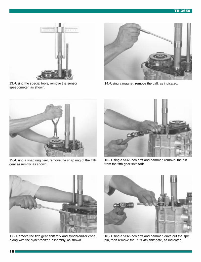
13.-Using the special tools, remove the sensorspeedometer, as shown.
14.-Using a magnet, remove the ball, as indicated.
15.-Using a snap ring plier, remove the snap ring of the fifthgear assembly, as shown
16.- Using a 5/32-inch drift and hammer, remove the pinfrom the fifth gear shift fork.
17.- Remove the fifth gear shift fork and synchronizer cone,along with the synchronizer assembly, as shown.
18.- Using a 5/32-inch drift and hammer, drive out the splitpin, then remove the 3rd & 4th shift gate, as indicated

19
19.- Using a 5/32-inch drift and hammer, drive out the splitpin then remove the 1st & 2nd shift gate.
21.-Remove the plastic spacer, as shown. 22.-Remove the two needle bearings and the spacer, asindicated.
23.- Using a magnet, remove the ball, as shown.
20.- Remove the main shift rail, as indicated.
24.-Remove the thrust washer, as indicated.

TR-3650
20
CAUTION:
Do not remove all bolts while thehorizontal position.
!
25.-Remove the two bolts from the shift interlck palte, asshown.
26.- Remove the shift interlock plate, as indicated
27.- Using a magnet, remove the interlock pins, as shown. 28.-Position the interlock, and lock pin on the center rail,two between the rails.
29.- Rotate the transmission to a horizontal position.Remove 12 bolts, leaving two opposing bolts in. Rotate thetransmission to a vertical position, them remove theremaining two bolts.

21
30.- Carefully pry the clucht housing from the transmissionmain case, as shown.
31.- Remove the trnsmission case from the clucht housing,as indicated. Use a hook to hold the bearing cone to avoidinterference with the cluster gear.

TR-3650
22
32 .- Remove the three detent plugs, as shown
CONTROL PARTS GROUP DISASSEMBLY
33.- Position the three detent plugs, springs and the de-tents, as indicated.
SELECTOR RAIL
SEAT SELECTOR GATE
SPACER FRONT
ROLLER BEARING
ROLL PINROLL PIN
ARM SELECTOR INHIBITOR
SPACER FRONTROLLER BEARING
ROLL PIN
NYLON STOP1st & 2ND GATE
1st & 2ND GATE ASS’Y1st & 2ND FORK
SHIFT
1st & 2ND FORKSHIFT ASS’Y
PAD
1st & 2ND SHIFT RAIL 3rd & 4TH FORK SHIFT
PAD
3rd & 4TH FORKSHIFT ASS’Y
3rd & 4TH SHIFT RAIL
5TH & REV SHIFT RAIL
REVERSE FORKSHIFT
PAD
REVERSE FORKSHIFT ASS’Y
5TH FORK SHIFT
PAD
5TH FORK SHIFT ASS’Y
ROLL PIN
NYLON STOP
ROLL PIN
3rd & 4TH GATE

23
36 .- Using a 5/32-inch drift and hammer, remove the splitpin from the 3rd & 4th. fork and shift rail.
35.-Remove the 1st. & 2nd, fork and shift rail, as indicated.
37.- Remove the 3rd & 4th., fork and rail as indicated.
38.-Using a 5/32-inch drift and hammer, remove the split pinfrom the reverse fork and shift rail.
34.- Using a 5/32-inch drift and hammer, remove the splitpin. From the 1st & 2nd fork and shift rail.
39.- Remove the reverse fork and rail as indicated.

TR-3650
24
PRIMARY GEAR PARTS GROUP DISASSEMBLY
NEEDLE BEARING ASS’Y
SNAP RING
REVERSE GEAR SPEED
BUSHING 3rd GEAR
BALL
THRUST WASHER
BEARING CONE
BEARING CUP
5th GEAR SPEED
BALL
SPEEDOMETER GEAR
SNAP RINGSPEEDOMETER
BEARING ASS’Y
INSERT SYNCHRONIZER
SPRING SYNCHRONIZER
1st & 2nd HUB SYNCHRO
SNAP RING HUBSYNCHRO 1st & 2nd
1st & 2nd SLEEVE
1st BLOCKER RING
1st BLOCKER RING& LINING ASSY
1st BLOCKER RING
NEEDLE BEARING ASS’Y
1st CLUTCH CONE
1st GEAR SPEED
REVERSE BLOCKER RING
REVERSE SLEEVE
INSERT SYNCHRONIZER
SPRING SYNCHRONIZER
REVERSE HUB SYNCHRO
SNAP RING TOP INSERT
1st & 2nd
SYNCHROASS’Y
REVERSE CLUTCH CONE
SNAP RING
3rd CLUTCHCONE
3rd GEAR SPEED
NEEDLE BEARINGASS’Y
3rd GEAR BUSHING
BALL
THRUST WASHER
NEEDLE BEARING ASS’Y
2nd GEAR SPEED
2nd CLUTCH CONE
2nd BLOCKER RING
2nd BLOCKER RING &LINING ASS’Y
2nd BLOCKER RING
MAIN SHAFT
SNAP RING
1st GEAR SPEED ASS’Y
INSERT SYNCHRO.
SPRING SYNCHRO.
3rd GEARSPEED ASS’Y
3rd/4th HUB SYNCHRO
3rd/4th SLEEVE3rd BLOCKER RING
2nd GEAR SPEEDASS’Y
25
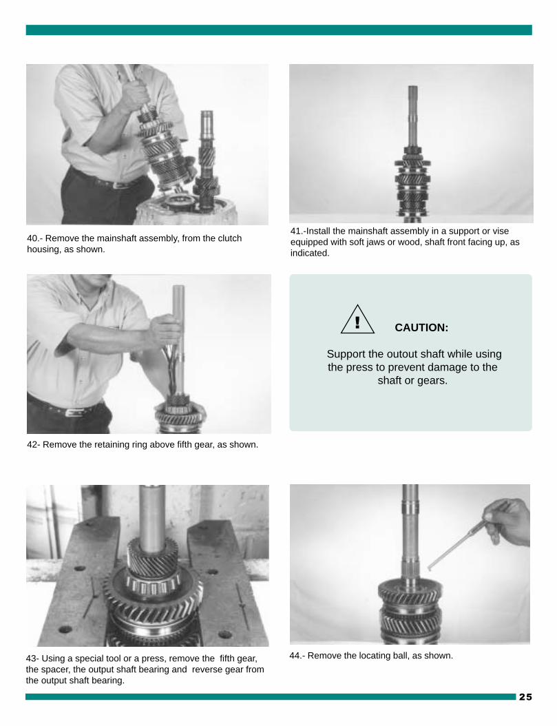
41.-Install the mainshaft assembly in a support or viseequipped with soft jaws or wood, shaft front facing up, asindicated.
40.- Remove the mainshaft assembly, from the clutchhousing, as shown.
42- Remove the retaining ring above fifth gear, as shown.
43- Using a special tool or a press, remove the fifth gear,the spacer, the output shaft bearing and reverse gear fromthe output shaft bearing.
44.- Remove the locating ball, as shown.
CAUTION:
Support the outout shaft while usingthe press to prevent damage to the
shaft or gears.
!

TR-3650
26
45.- Remove reverse gear needle bearing, as shown. 46.- Remove the reverse gear blocking ring, as indicated.
47.- Remove the clutch cone, as shown. 48.- Remove the first gear, as indicated.
49.-Remove the needle bearing from first gear, as shown. 50.- Remove the first gear synchronizer inner cone, asindicated.

27
51.- Remove the outer first gear synchronizer cone, asshown.
52.- Remove the first gear synchronizer blocking ring, asindicated.
53.- Rotate the output shaft with the input end facingupward and remove the input shaft bearing race, as shown
54.- With a snap ring plier, remove the hub snap ring,asindicated.
55.- Remove the 3rd & 4th speed synchronizer, as shown. 56.- Remove the 3rd speed synchronizer blocking ring, asindicated.

TR-3650
28
57.- Remove the third speed gear, as shown. 58.- Remove the third gear needle bearing, as indicated.
59.- Using a special tool or a press, remove the spacer,thrust washer and second speed gear
61.- Remove the second speed gear needle bearing, asindicated.
60.- Remove the locating ball, as shown.
NOTE:Install the special tool behind
second gear with the flat side of thetool facing second gear

29
63.- Remove the second speed gear synchronizer outercone, as indicated.
64.- Remove the second speed gear synchronizer blockerring, as shown.
65.- Using a snap ring pliers, remove the 3rd & 4th hub snapring, as indicated.
66.- Using a special tool or a press, remove the 3rd & 4thSynchronizer, as shown
62.-Remove the second speed gear synchronizer innercone, as shown.

TR-3650
30
SECONDARY GROUP DISASSEMBLY
67.- Remove the countershaft, as shown. 68.- Remove the cone bearing, as indicated.
BEARINGSHIM
BEARING TAPEREDROLLER CUP
BEARING TAPEREDROLLER ASS’Y
COUNTER GEAR
BEARING TAPEREDROLLER CONE
BEARING TAPEREDROLLER CUP
THRUST WASHER
BALL
5th GEAR C.S.
SPACER
SNAP RING TOPINSERT
5th HUB SYNCHRO
INSERT SYNCHRO.
SPRING SYNCHRO.
5th SLEEVE
BLOCKER RING
CLUTCH CONE 5th SPEED C.S.
SNAP RING C.S. (A.R.)
BOLT TORX BOTTON HEAD
O’RING
REVERSE SUPPORT SHAFT
REVERSE SHAFT RAIL
REVERSE IDLER GEAR
ROLLER BEARING
SPACER
ROLLER BEARING GEAR 5th
BEARING TAPEREDROLLER CONE
BEARING TAPEREDROLLER ASS’Y
SYNCHRO. ASS’Y
31
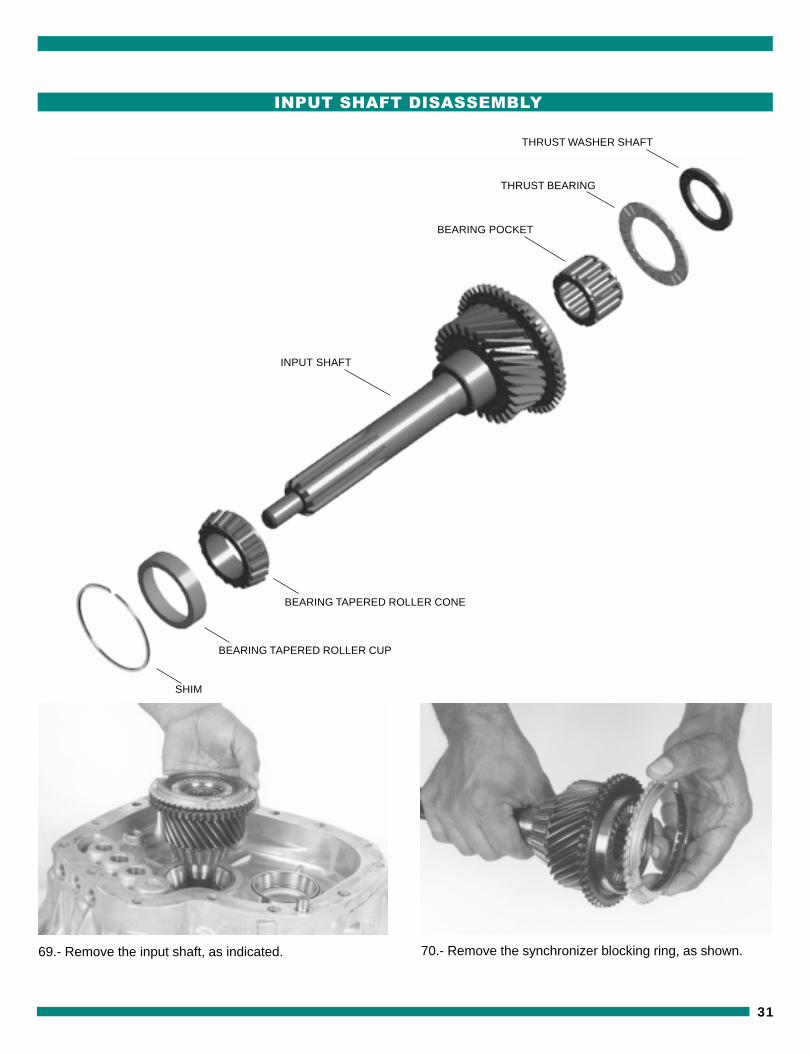
INPUT SHAFT DISASSEMBLY
69.- Remove the input shaft, as indicated. 70.- Remove the synchronizer blocking ring, as shown.
THRUST WASHER SHAFT
THRUST BEARING
BEARING POCKET
INPUT SHAFT
BEARING TAPERED ROLLER CONE
BEARING TAPERED ROLLER CUP
SHIM

TR-3650
32
71.- Remove the axial bearing, as shown. 72.- Remove the input shaft needle bearing, as shown.
73.- Using a special tool or a press, remove the conebearing from the input shaft, as shown.

33
CASE PARTS GROUP DISASSEMBLY
74.- Remove the cup bearing, from the main drive asshown.
75.- Remove the shim bearing, from the main drive asindicate.
TUB RETAINER BEARING
BOLT METRIC HEX WASHER HEAD
CLUTCH HOUSING
DETENT
ACTUATING SPRINGS
DETENT PLUG
DOWELL PIN
STUD CLUTCHRELEASE
PIN DOWELL
BREATHER
SWITCH ASS’YBACKUP LAMP
DRAIN PLUG
SHIPTERINTERLOCK
INTERLOCK SUPPORT
BOLT
CENTERINTERLOCKPIN
SHIPTERINTERLOCK
TRANSMISSION CASE
TR-3650
34
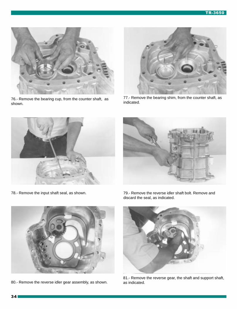
76.- Remove the bearing cup, from the counter shaft, asshown.
77.- Remove the bearing shim, from the counter shaft, asindicated.
78.- Remove the input shaft seal, as shown. 79.- Remove the reverse idler shaft bolt. Remove anddiscard the seal, as indicated.
80.- Remove the reverse idler gear assembly, as shown.81.- Remove the reverse gear, the shaft and support shaft,as indicated.

35
82.-Remove the reverse idler gear bearing. The reverseidler gear is three separate pieces: bearing, spacer,
bearing, as shown.
83.- Remove the reverse switch, as indicated.

TR-3650
36
EXTENSION DISASSEMBLY
84.- Remove the fifth & reverse inhibitor bolt, as shown. 85.-Remove the fifth & reverse lockout inhibitor, as indi-cated.
SEAL OUTPUT SPLINE
OIL SEAL EXTENSION
BUSHINGEXTENSION
EXTENSION
BOLTMETRIC
PIN DOWELL
PIN INHIBITOR
SPRING BASE TURRET
SPRING CENTERINGSHIFT CONTROL
BOLT SHOULDER
WASHER SPRINGRETENTION
DETENT PLUG
RAIL REVERSE INHIBITOR
SPRING INHIBITOR
ROLL PIN
INHIBITORREVERSE
O’RING
FILLER PLUG
MAGNET
SENSOR SPEEDOMETER
CAP SCREW HEX HEAD SENSOR
PIN DOWELL

37
86.- Remove the sensor bolt, as shown. 87.- Remove the sensor, as indicated.
88.- Using a special tools, remove the extensión housingfluid seal, as shown.

TR-3650
38
ENSAMBLE DE LA REVERSA
1.-Inspect the gear and bearing for wear or damage. Installnew as necessary.
2.- Install the reverse idler gear assembly, as indicated.
3.- Install a new seal and the reverse idler shaft bolt, asshown.
4.- Install the reverse switch, as indicated.
5.- If previously removed, install the extension seal with theproper seal driver.
6.-Install the sensor, as indicated.
REASSEMBLY REVERSE GEAR

39
7.- Install the sensor bolt, as shown. 8.- Install the fifth & reverse lockout, as indicated.
9.-Install the fifth & reverse gear lockout bolt, as shown. 10.-Install the mainshaft in a support or vise with soft jawsor wood, shaft front facing up, as indicated.
11.- Install 1st & 2nd synchronizer assembly, as shown 12.- Using a special tool or press, install the 1st & 2nd
synchronizer, as indicated.

TR-3650
40
13.- Using a snap ring plier, install the of 1st & 2nd hub snapring, as shown.
14.-Install the second gear synchronizer blocker ring, alignthe blocking ringtabs with sinchronizer assembly.
15.- Install the second gear synchronizer outer cone, asshown.
16.- Install the second gear synchronizer inner cone, asindicated.
17.- Install the second gear needle bearing, lubricate withthe recommended transmission fluid.
18.- Install the 2nd speed gear, as indicated, rotate the gearto align gear slots with inner cone tabs.

41
19.- Install the locating ball, as shown. 20.- Install the thrust washer, as indicated.
21.- Using a special tool or a press, install the spacer, thrustwasher and second speed gear, as shown.
22.- Install the third gear needle bearing, lubricate with therecommended transmission fluid,as shown.
23 .- Install the third speed gear, as indicated. 24 .- Install the 3rd speed synchronizer blocking ring, asshown.

TR-3650
42
30.- Install the inner first gear synchronizer cone, rotate theinner cone till it is seated, as indicated.
25 .- Install the 3rd & 4th speed synchronizer, as indicated. 26.- Using a snap ring plier, install the 3rd & 4th hub snapring, as shown.
27.- Install the input shaft bearing race, as indicated. 28.- Install the first gear synchronizer blocking ring, alignthe blocking ring tabs with the synchronizer assembly.Rotate mainshaft with synchronizer up, as shown.
29.- Install the outer first gear synchronizer cone, asshown.

43
31.- Install the first gear needle bearing lubricate with therecommended transmission fluid.
33.- Install the reverse clutch cone, as shown. 34.-Install the reverse gear blocking ring, as indicated
32- Install the first speed gear, rotate the gear to aligngear slots with the inner cone tabs.
35.-Install the reverse gear bearing spacer, as shown. 36.- Use a special tool or a press to install, as indicated.

TR-3650
44
37.-Install reverse gear needle bearing, lubricate with therecommended transmission fluid,as shown.
38.- Install reverse gear, rotate gear to align the gear slotswith the inner cone tabs.
39.- Using a magnet, Install the ball, use grease to hold theball in place.
40.- Install the thrust washer. Be sure to align the slot in thewasher with the ball.
41.- Instal the bearing cone, as shown. 42.- Use a special tool or a press to install, as indicated.

45
43.- Intalll the 5th speed gear, as shown. 44.- Use a special tool or a press to install, as indicated.
45- Using a snap ring plier, install the 5th gear snap ring,as indicated.
46.- Using a special tool or press, install the countershaftbearing cone, as shown.
47.- Using a special tool, install the input shaft seal. 48.- Install the appropriate shims to achieve the proper endplay, this total gives you a shim pack thickness to start theend play measurement.

TR-3650
46
49.-. Install the front countershaft bearing cup, as indicated. 50.- Install the appropriate shims to achieve the proper endplay, this total gives you a shim pack thickness to start theend play measurement.
51.- Install the front input shaft bearing cup, as indicated. 52.- Using a special tool or press, install input shaft bearingcone, as shown.
53.- Install the input shaft needle bearing, as indicated 54.- Install the input shaft bearing, as shown.

47
55.- Install the synchronizer blocking ring, as indicated. 56.- Install the input shaft, as shown.
57.- Install the countershaft, as indicated.
60.-Install the countershaft bearing cone, as shown.59.-Install a tube as a guide when installing the countershaft bearing cone, as indicated.
58.- Install the main shaft assembly, as shown.

TR-3650
48
61.- Hold the cone and install the transmission case, asindicated.
62.- Install temporarily the transmission case, as shown.
63.- Using a 13 mm socket install the (2) two bolts that holdthe case and tighten to the specified torque (18-28 lb-ft). asindicated.
64.- Position a dial indicator as shown on the output shaftpry on the 5th gear. End play must be between 0.001”-0.005”
65.-Position a dial indicator as shown on the transmissioncase pry on countershaft. End play must be between 0.001”-0.005”.
NOTE:Add shims for less and play or remove
shims for more endplay. To add or remove shims refer to views
48 & 50

49
67.- Install the reverse & 5th rail, as indicated.
68.- Using a 5/32-inch drift and hammer, install the split pinon the reverse fork and shift rail.
66.- Install the reverse fork, as shown.
69.- Install the 3rd & 4th fork, as shown.
70.- Install the 3rd & 4th. rail, as indicated. 71.- Using a 5/32-inch drift and hammer, install the split pin

TR-3650
50
74.- Using a 5/32-inch drift and hammer, install the split pin.from the 1st & 2nd fork and shift rail.
75.- Install the detents and detent springsk, as indicated.
76.- Install the three detent plugs, as shown 77.- Clean the mating surfaces of the transmission maincase and the clutch housing. Apply a bead of siliconerubber to the sealing surface on the clutch housing theninstall the transmission main case.
73.- Install the 1st & 2nd rail, as indicated.72.- Install the 1st & 2nd fork, as shown.

51
79.-Using a 13 mm socket, install the (14) bolts and tightento the recommended torque.
80.- Arrange the lock pin, as indicated. 81.- Using a magnet, install the lock pin in the center rail, asshown
82.- Using a magnet, install the interlock pins, as indicated. 83.- Install the shift interlock plate, as shown.
78.- Install the transmission case, as shown.

TR-3650
52
85.- Tighten to the recommended torque
86.- Using a magnet install the locating ball, as indicated. 87.- Install the thrust washer, as shown.
88.- Install the two needle bearing and spacer, as indicated. 89.- Install the plastic spacer, as shown.
84.- Install the shift interlock plate bolts, as indicated.

53
91.- Install the 1st & 2nd shift finger, as shown.
92.- Using a 5/32-inch drift and hammer, install the 1st & 2nd
Gate pin on the shift rail, as shown.93.- Install the 3rd & 4th shift finger, as shown.
94.-Using a 5/32-inch drift and hammer, install the 3rd & 4th
gate pin on the shift rail.95.-Install the 5th gear shift fork, the synchronizer assembly,the synchronizer cone and fifth gear as an assembly.
90.- Install the main shift rail, as indicated.

TR-3650
54
100.-Using the snap ring plier, install the sensor snap ring,as indicated.
101.- Clean the mating surfaces of the transmission maincase, and the extension housing. Apply a bead of siliconerubber to the sealing surface of the transmission case.
99.- Install the speedometer sensor, as indicated.
97.-Using a snap ring plier, install the 5th gear snap ring,as indicated.
96.- Using a 5/32-inch drift and hammer, install the 5th forkpin on the shift rail.
98.- Install the ball for speedometer, using a magnet, asshown.

55
104.- Install the fill plug, as shown. 105.-Using a 10 mm. socket tighten to the recommendedtorque.
106.-Using a 5/32-inch drift and hammer, install the off setlever pin, as shown.
107 .- Install the shift spring and plate, as indicated.
102.- Install the extension housing and at the same timeinstall the gear shift off-set lever.
103.- Install the (12) bolts and tighten to the recommendedtorque, as indicated.

TR-3650
56
110.-Using a socket, Install the bolt on plate , as shown. 111.-Using a 10 mm socket tighten to the recommendedtorque, (see torque recommendations).
112.- Install the control turret assembly, as shown 113.- Install the four bolts and tighten to the recommendtorque, as indicated.
109.-Using a 10 mm socket tighten to the recommendedtorque, as indicated.
108.- Using a 1/4“ socket, install the bolts , as shown.

57
GUIA PARA LOCALIZACION DE PROBLEMAS
PROBLEM POSSIBLE CAUSE REMEDY
Will not shift Control lever assy broken or damaged Replace control lever and housing assy(Control lever Moves)
Damaged offset lever, shift plate, or Remove extension or adapter and caseselector, armloose rail bushings. cover. Check for damaged parts.Broken roll pins in offset levers of Replace damaged parts.selector arm.
Hard shift or control Clutch not releasing Adjust or replace clutchlever will not moveinto gear Improper or low transmission lubricant Add or drain and replace with proper lubricant
Shifter rail binding Remove extension or adapter and case cover.Check for damaged parts. Replace damagedparts
Binding of sliding synchronizers or gears Remove extension and case to check thatsynchronizers and gears slide freely on shafts.Remove and replace damaged parts
If reverse only, seized backup switch Remove and check backup switch. Replace ifseized
Worn or damaged flywheel pilot bushing Replace pilot bushing
Bell housing misaligned Align bell housing to within 0.010 inch TIR onface and in bore
Gears clash when Engine idle speed too high Adjust idle speed to specificationsshifting
Clutch damaged or out of adjustment Adjust or replace clutch
Bent shift forks or worn fork pads Disassemble and check. Replace damagedparts
Damaged synchronizer Disassemble and check for damagedsynchronizer parts. Replace damaged parts
Pilot bearing between input shaft and Disassemble and check bearing rollers, inputoutput shaft binding shaft ID and output shaft OD. Replace dam
aged parts
Bell housing misaligned Align bell housing to within 0.010 inch TIR onface and in bore
Damaged gears Disassemble and check for gear damage.Replace damaged gears
Worn or damaged flywheel pilot bushing Replace pilot bushing
TR-3650 ON-VEHICLE SERVICE AND TROUBLESHOOTING

TR-3650
58
Transmission jumps Synchronizer damaged or Disassemble and check for worn or damagedout of gear excessively worn synchronizer parts. Replace damaged parts.
Blocking ring damaged, worn index slots Disassemble and check blocking ring for wearor friction surfaces worn or damaged or damage. Replace worn or damaged parts
Excessive countershaft end play Disassemble and check. Replace worn ordamaged parts. Reshim if necessary
Shifting fork loose on shift rail; Disassemble and check for wear or damage.worn or damaged fork or fork pads Replace worn or damaged parts
Transmission locked Fork or offset lever loose on shift rail Remove extension and case to check for loosein one gear parts on shift rail. Replace roll pin(s). If still
loose, replace shift rail and/or attached parts asrequired
Worn or damaged forks, offset lever, Remove extension or adapter and case cover.shift rail, broken roll pins in offset levers. Check for wear or damage.
Replace damaged parts.
Worn or damaged synchronizer Disassemble and check for worn or damagedsynchronizer parts. Replace worn or damagedparts.
Worn or damaged gears Disassemble and check for worn or damagedgears. Replace worn or damaged gears.
Transmission noise Improper or low transmission lubricant Add or drain and replace with proper lubricant.NOTE: Make surenoise is coming from Loose bolts or other attaching parts Make sure all attaching parts are torqued totransmission and not specificationsclutch release bearingor other components. Improper flywheel housing to engine Check alignment and correct if necessary per
crankshaft alignment vehicle service manual
Noisy transmission bearings Disassemble and check bearings, bearingrollers and parts in and on which they operatefor wear or damage. Replace worn or damagedparts
Noisy gears Disassemble and check for worn or damagedgears (including speedometer gear). Replaceworn or damaged gears
PROBLEM POSSIBLE CAUSE REMEDY
59
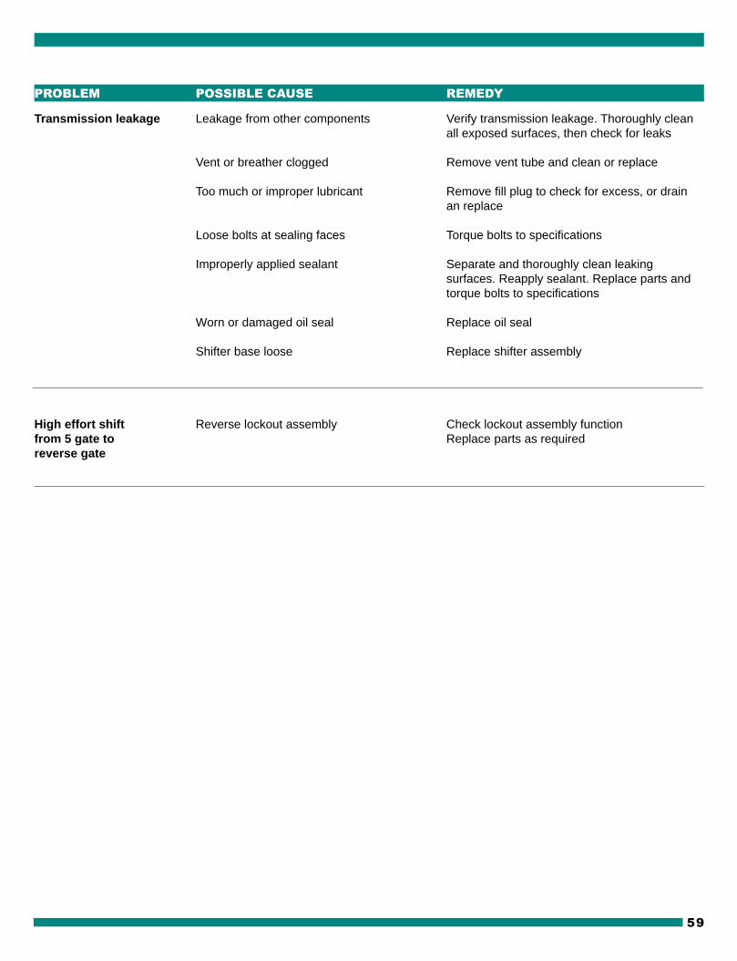
Transmission leakage Leakage from other components Verify transmission leakage. Thoroughly cleanall exposed surfaces, then check for leaks
Vent or breather clogged Remove vent tube and clean or replace
Too much or improper lubricant Remove fill plug to check for excess, or drainan replace
Loose bolts at sealing faces Torque bolts to specifications
Improperly applied sealant Separate and thoroughly clean leakingsurfaces. Reapply sealant. Replace parts andtorque bolts to specifications
Worn or damaged oil seal Replace oil seal
Shifter base loose Replace shifter assembly
High effort shift Reverse lockout assembly Check lockout assembly functionfrom 5 gate to Replace parts as requiredreverse gate
PROBLEM POSSIBLE CAUSE REMEDY

TR-3650
60
HERAMIENTAS UTILIZADAS
TORQUE WRENCHES
PULLERS BEARINGAND BEARING SEPARATORS
JUEGO DE SOCKET SET
FEELER GAGES
BALL PEIN HAMMER
SOFT FACET HAMMER
PLIERS
SNAP RING PLIERS
HEX KEY SET
GASKET ELIMINATOR
TOOLS
DRIFT PUNCHES
40 TORK, 40 TORK PLUS