tri-packs trays • column internals - dust · pdf file• excellent gas and liquid...
TRANSCRIPT

TO
WE
R P
AC
KIN
GS
• T
RA
YS
• C
OL
UM
N I
NT
ER
NA
LS
Tri-PacksProduct Bulletin 600
JAEG
ER Features
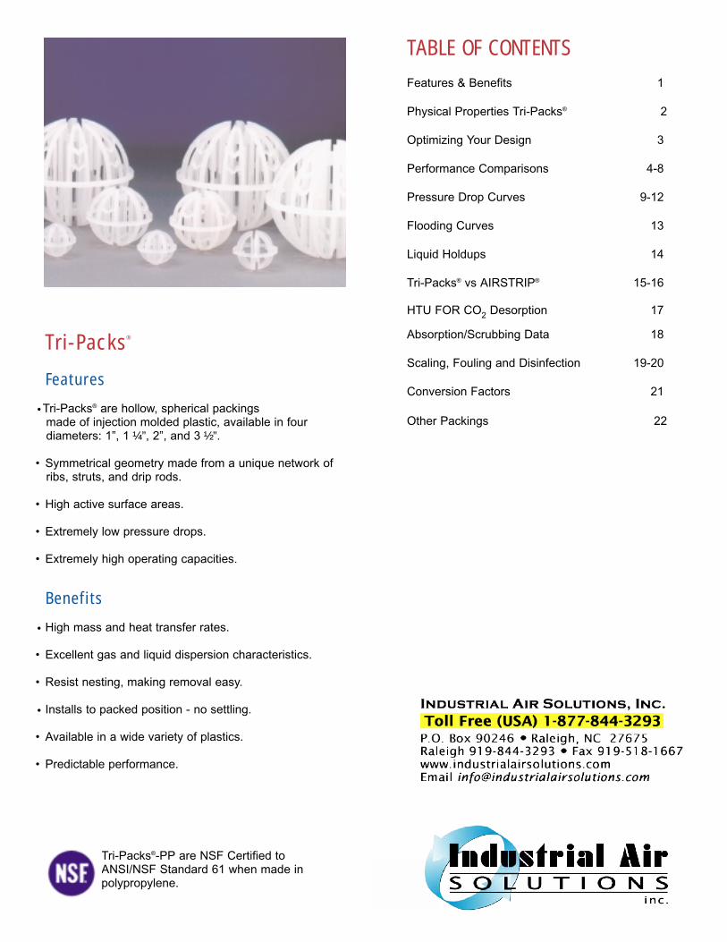
•Tri-Packs® are hollow, spherical packings made of injection molded plastic, available in four diameters: 1”, 1 ¼ ”, 2”, and 3 ½ ”.
• Symmetrical geometry made from a unique network of ribs, struts, and drip rods.
• High active surface areas.
• Extremely low pressure drops.
• Extremely high operating capacities.
Benefits
• High mass and heat transfer rates.
• Excellent gas and liquid dispersion characteristics.
• Resist nesting, making removal easy.
• Installs to packed position - no settling.
• Available in a wide variety of plastics.
• Predictable performance.
Tri-Packs®
Tri-Packs®-PP are NSF Certified toANSI/NSF Standard 61 when made inpolypropylene.
TABLE OF CONTENTS
Features & Benefits 1
Physical Properties Tri-Packs® 2
Optimizing Your Design 3
Performance Comparisons 4-8
Pressure Drop Curves 9-12
Flooding Curves 13
Liquid Holdups 14
Tri-Packs® vs AIRSTRIP® 15-16
HTU FOR CO2 Desorption 17
Absorption/Scrubbing Data 18
Scaling, Fouling and Disinfection 19-20
Conversion Factors 21
Other Packings 22
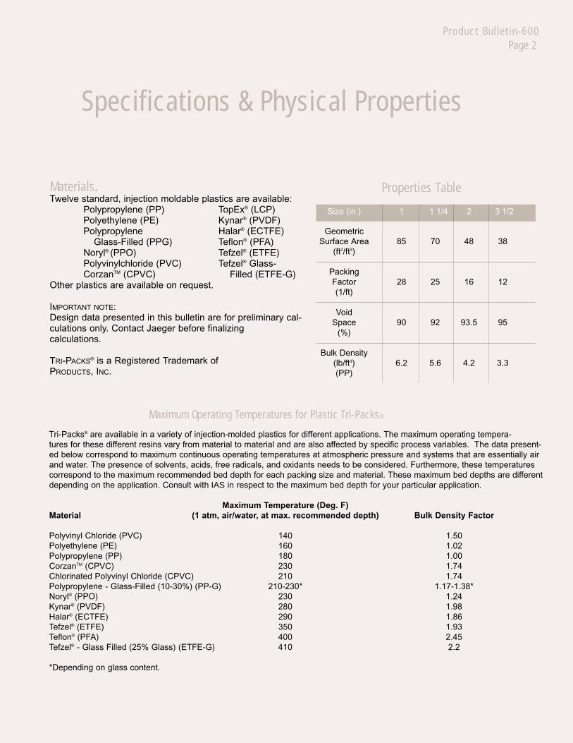
Properties Table
Size (in.) 1 1 1/4 2 3 1/2
GeometricSurface Area 85 70 48 38
(ft2/ft3)
PackingFactor 28 25 16 12(1/ft)
VoidSpace 90 92 93.5 95
(%)
Bulk Density(lb/ft3) 6.2 5.6 4.2 3.3(PP)
Materials.Twelve standard, injection moldable plastics are available:
Polypropylene (PP) TopEx® (LCP)Polyethylene (PE) Kynar® (PVDF)Polypropylene Halar® (ECTFE)
Glass-Filled (PPG) Teflon® (PFA)Noryl® (PPO) Tefzel® (ETFE)Polyvinylchloride (PVC) Tefzel® Glass-CorzanTM (CPVC) Filled (ETFE-G)
Other plastics are available on request.
IMPORTANT NOTE:Design data presented in this bulletin are for preliminary cal-culations only. Contact Jaeger before finalizing calculations.
TRI-PACKS® is a Registered Trademark of PRODUCTS, INC.
Maximum Operating Temperatures for Plastic Tri-Packs®
Tri-Packs® are available in a variety of injection-molded plastics for different applications. The maximum operating tempera-tures for these different resins vary from material to material and are also affected by specific process variables. The data present-ed below correspond to maximum continuous operating temperatures at atmospheric pressure and systems that are essentially airand water. The presence of solvents, acids, free radicals, and oxidants needs to be considered. Furthermore, these temperaturescorrespond to the maximum recommended bed depth for each packing size and material. These maximum bed depths are differentdepending on the application. Consult with IAS in respect to the maximum bed depth for your particular application.
Maximum Temperature (Deg. F)Material (1 atm, air/water, at max. recommended depth) Bulk Density Factor
Polyvinyl Chloride (PVC) 140 1.50Polyethylene (PE) 160 1.02Polypropylene (PP) 180 1.00CorzanTM (CPVC) 230 1.74Chlorinated Polyvinyl Chloride (CPVC) 210 1.74Polypropylene - Glass-Filled (10-30%) (PP-G) 210-230* 1.17-1.38*Noryl® (PPO) 230 1.24Kynar® (PVDF) 280 1.98Halar® (ECTFE) 290 1.86Tefzel® (ETFE) 350 1.93Teflon® (PFA) 400 2.45Tefzel® - Glass Filled (25% Glass) (ETFE-G) 410 2.2
*Depending on glass content.
Specifications & Physical Properties
Product Bulletin-600Page 2
Superior Performance by Design
Product Bulletin-600Page 3
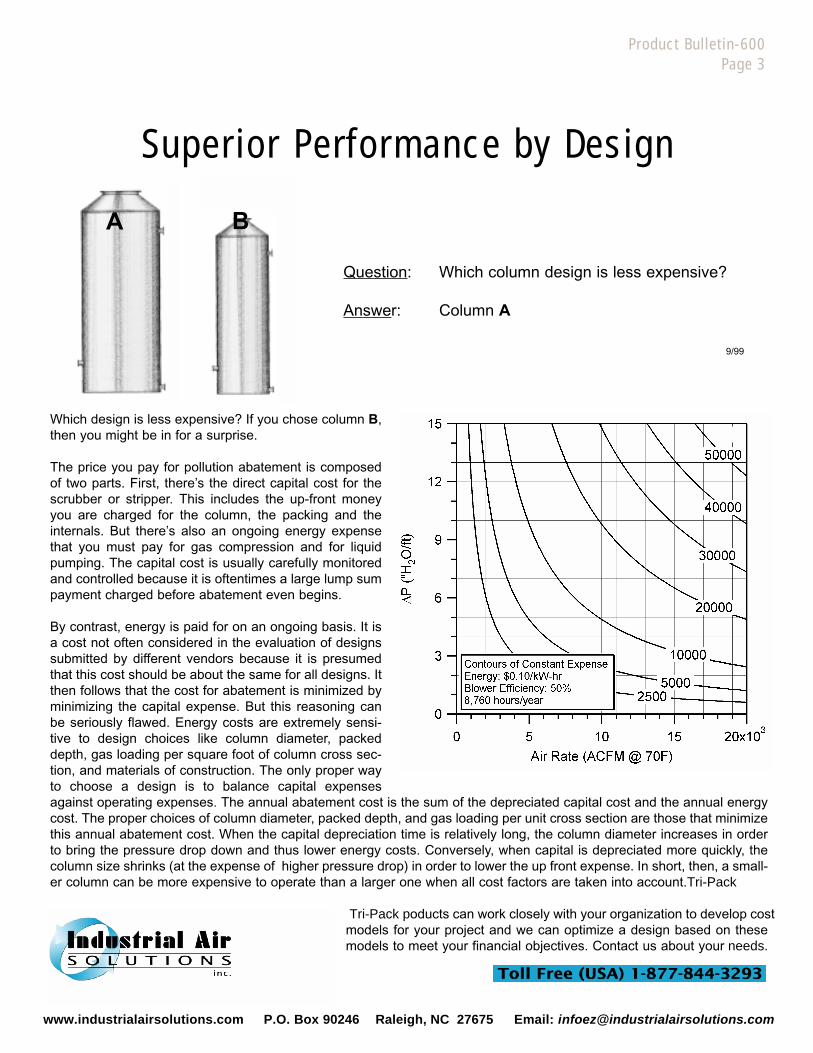
Question: Which column design is less expensive?
Answer: Column A
Which design is less expensive? If you chose column B,then you might be in for a surprise.
The price you pay for pollution abatement is composedof two parts. First, there’s the direct capital cost for thescrubber or stripper. This includes the up-front moneyyou are charged for the column, the packing and theinternals. But there’s also an ongoing energy expensethat you must pay for gas compression and for liquidpumping. The capital cost is usually carefully monitoredand controlled because it is oftentimes a large lump sumpayment charged before abatement even begins.
By contrast, energy is paid for on an ongoing basis. It isa cost not often considered in the evaluation of designssubmitted by different vendors because it is presumedthat this cost should be about the same for all designs. Itthen follows that the cost for abatement is minimized byminimizing the capital expense. But this reasoning canbe seriously flawed. Energy costs are extremely sensi-tive to design choices like column diameter, packeddepth, gas loading per square foot of column cross sec-tion, and materials of construction. The only proper wayto choose a design is to balance capital expensesagainst operating expenses. The annual abatement cost is the sum of the depreciated capital cost and the annual energycost. The proper choices of column diameter, packed depth, and gas loading per unit cross section are those that minimizethis annual abatement cost. When the capital depreciation time is relatively long, the column diameter increases in orderto bring the pressure drop down and thus lower energy costs. Conversely, when capital is depreciated more quickly, thecolumn size shrinks (at the expense of higher pressure drop) in order to lower the up front expense. In short, then, a small-er column can be more expensive to operate than a larger one when all cost factors are taken into account.Tri-Pack
Tri-Pack poducts can work closely with your organization to develop costmodels for your project and we can optimize a design based on thesemodels to meet your financial objectives. Contact us about your needs.
9/99
A B
www.industrialairsolutions.com P.O. Box 90246 Raleigh, NC 27675 Email: [email protected]
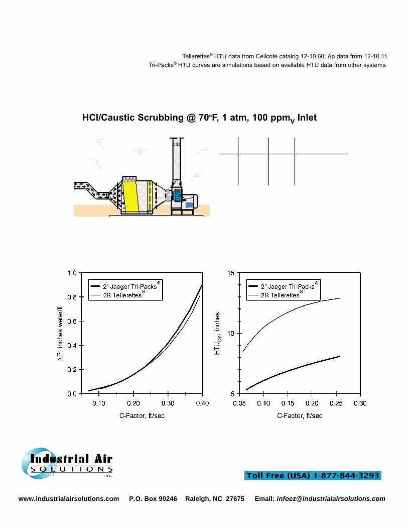
HCl/Caustic Scrubbing @ 70oF, 1 atm, 100 ppmV Inlet
Performance Comparison2R Tellerettes®
vs 2” Tri-Packs®
Tellerettes® HTU data from Ceilcote catalog 12-10.60; ∆p data from 12-10.11Tri-Packs® HTU curves are simulations based on available HTU data from other systems.
Product Bulletin-600Page 4
9,000 CFM @ 70oF100 ppmv HCl
ppmV Removal ∆p/H
Out Effcy. % “H2O/ft
17.5 82.5 0.11 2” Pall Rings3.8 96.2 0.065 2R Tellerettes®
3.8 96.2 0.042 3 1/2” Tri-Packs®
0.5 99.5 0.086 2” Tri-Packs®
-2” Tri-Packs® give a 97% improvement in outlet HCl concentration compared to 2” Pall Rings
-2” Tri-Packs® outperform 2R Tellerettes® by 87%-3 1/2" Tri-Packs® give a 78% improvement when
compared to 2” Pall Rings-3 1/2" Tri-Packs® equal 2R Tellerettes® performance
with 35% lower pressure drop.
9/99
www.industrialairsolutions.com P.O. Box 90246 Raleigh, NC 27675 Email: [email protected]
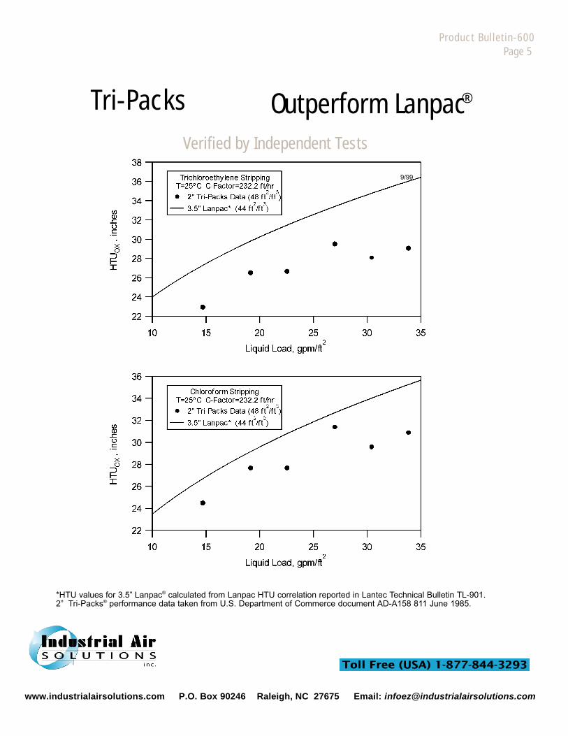
Tri-Packs Outperform Lanpac ®
Product Bulletin-600Page 5
*HTU values for 3.5” Lanpac® calculated from Lanpac HTU correlation reported in Lantec Technical Bulletin TL-901.2” Tri-Packs® performance data taken from U.S. Department of Commerce document AD-A158 811 June 1985.
9/99
Verified by Independent Tests
www.industrialairsolutions.com P.O. Box 90246 Raleigh, NC 27675 Email: [email protected]
Product Bulletin-600Page 6
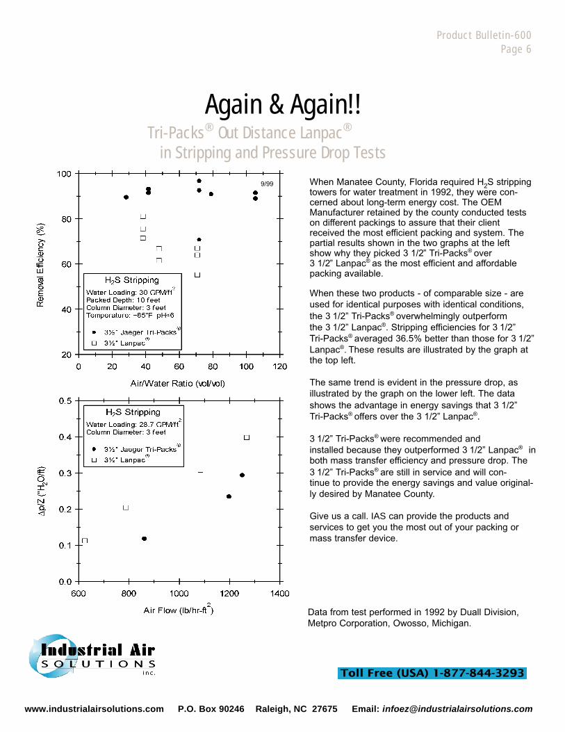
Again & Again!!Tri-Packs® Out Distance Lanpac®
in Stripping and Pressure Drop Tests
When Manatee County, Florida required H2S strippingtowers for water treatment in 1992, they were con-cerned about long-term energy cost. The OEMManufacturer retained by the county conducted testson different packings to assure that their clientreceived the most efficient packing and system. Thepartial results shown in the two graphs at the leftshow why they picked 3 1/2 ” Tri-Packs® over3 1/2 ” Lanpac® as the most efficient and affordablepacking available.
When these two products - of comparable size - areused for identical purposes with identical conditions,the 3 1/2” Tri-Packs® overwhelmingly outperformthe 3 1/2” Lanpac®. Stripping efficiencies for 3 1/2” Tri-Packs® averaged 36.5% better than those for 3 1/2”Lanpac®. These results are illustrated by the graph atthe top left.
The same trend is evident in the pressure drop, asillustrated by the graph on the lower left. The datashows the advantage in energy savings that 3 1/2”Tri-Packs® offers over the 3 1/2” Lanpac®.
3 1/2” Tri-Packs® were recommended andinstalled because they outperformed 3 1/2” Lanpac® inboth mass transfer efficiency and pressure drop. The3 1/2” Tri-Packs® are still in service and will con-tinue to provide the energy savings and value original-ly desired by Manatee County.
Give us a call. IAS can provide the products andservices to get you the most out of your packing ormass transfer device.
9/99
Data from test performed in 1992 by Duall Division,Metpro Corporation, Owosso, Michigan.
www.industrialairsolutions.com P.O. Box 90246 Raleigh, NC 27675 Email: [email protected]
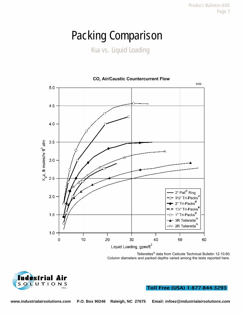
CO2 Air/Caustic Countercurrent Flow
Packing ComparisonKGa vs. Liquid Loading
Tellerettes® data from Ceilcote Technical Bulletin 12-10.60.Column diameters and packed depths varied among the tests reported here.
Product Bulletin-600Page 7
9/99
www.industrialairsolutions.com P.O. Box 90246 Raleigh, NC 27675 Email: [email protected]
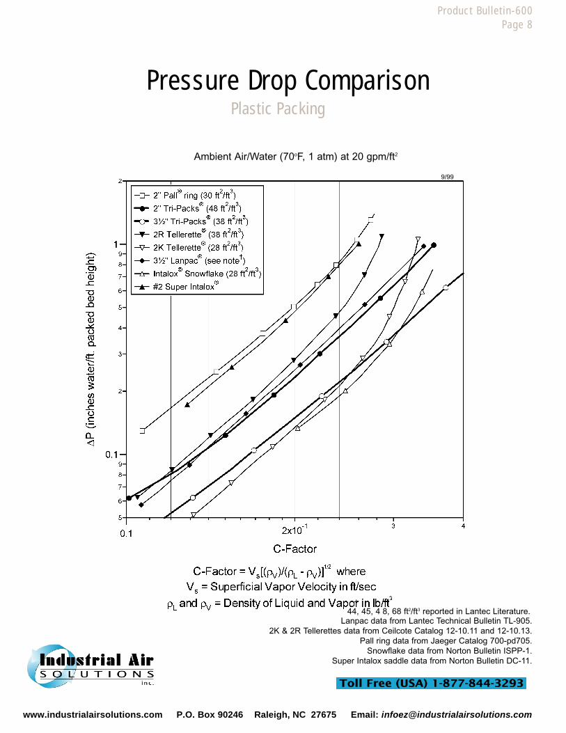
Ambient Air/Water (70oF, 1 atm) at 20 gpm/ft2
Pressure Drop ComparisonPlastic Packing
Product Bulletin-600Page 8
+44, 45, 4 8, 68 ft2/ft3 reported in Lantec Literature.
Lanpac data from Lantec Technical Bulletin TL-905.2K & 2R Tellerettes data from Ceilcote Catalog 12-10.11 and 12-10.13.
Pall ring data from Jaeger Catalog 700-pd705.Snowflake data from Norton Bulletin ISPP-1.
Super Intalox saddle data from Norton Bulletin DC-11.
9/99
www.industrialairsolutions.com P.O. Box 90246 Raleigh, NC 27675 Email: [email protected]
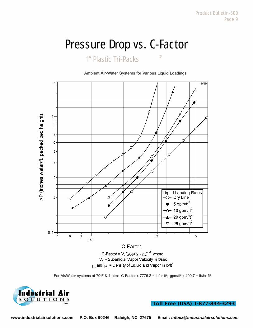
1” Plastic Tri-Packs ®
Pressure Drop vs. C-Factor
Product Bulletin-600Page 9
Ambient Air-Water Systems for Various Liquid Loadings
For Air/Water systems at 70oF & 1 atm: C-Factor x 7776.2 = lb/hr-ft2; gpm/ft2 x 499.7 = lb/hr-ft2
9/99
www.industrialairsolutions.com P.O. Box 90246 Raleigh, NC 27675 Email: [email protected]
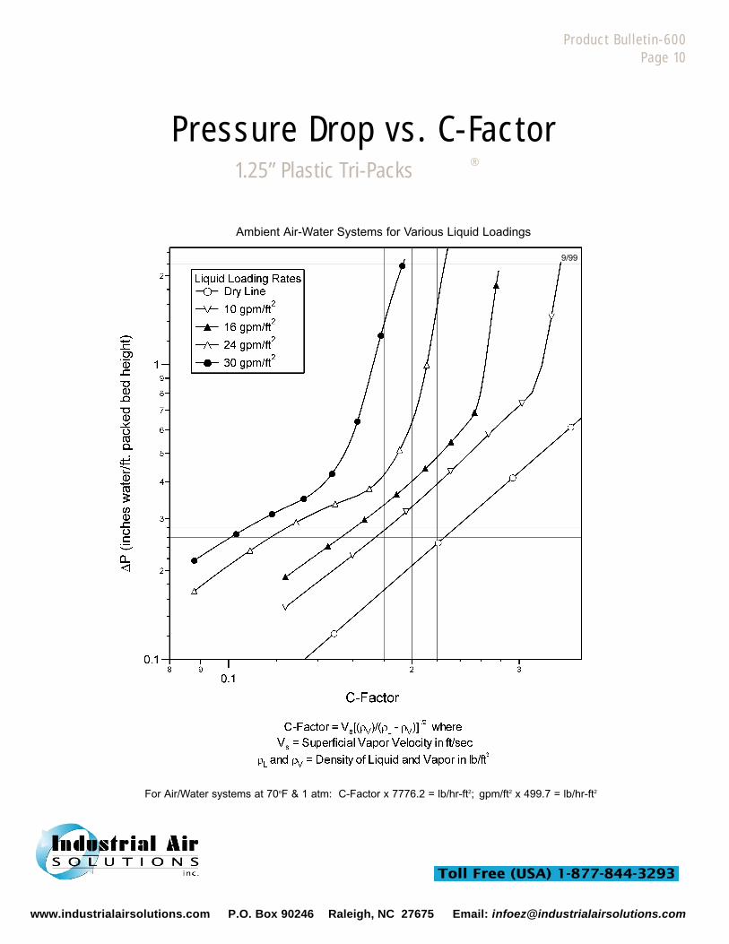
1.25” Plastic Tri-Packs ®
Pressure Drop vs. C-Factor
Product Bulletin-600Page 10
Ambient Air-Water Systems for Various Liquid Loadings
For Air/Water systems at 70oF & 1 atm: C-Factor x 7776.2 = lb/hr-ft2; gpm/ft2 x 499.7 = lb/hr-ft2
9/99
www.industrialairsolutions.com P.O. Box 90246 Raleigh, NC 27675 Email: [email protected]

2” Plastic Tri-Packs ®
Pressure Drop vs. C-Factor
Ambient Air-Water Systems for Various Liquid Loadings
Product Bulletin-600Page 11
For Air/Water systems at 70oF & 1 atm: C-Factor x 7776.2 = lb/hr-ft2; gpm/ft2 x 499.7 = lb/hr-ft2
9/99
www.industrialairsolutions.com P.O. Box 90246 Raleigh, NC 27675 Email: [email protected]

Product Bulletin-600Page 12
Ambient Air-Water Systems for Various Liquid Loadings
For Air/Water systems at 70oF & 1 atm: C-Factor x 7776.2 = lb/hr-ft2; gpm/ft2 x 499.7 = lb/hr-ft2
3.5” Plastic Tri-Packs ®
Pressure Drop vs. C-Factor
9/99
www.industrialairsolutions.com P.O. Box 90246 Raleigh, NC 27675 Email: [email protected]
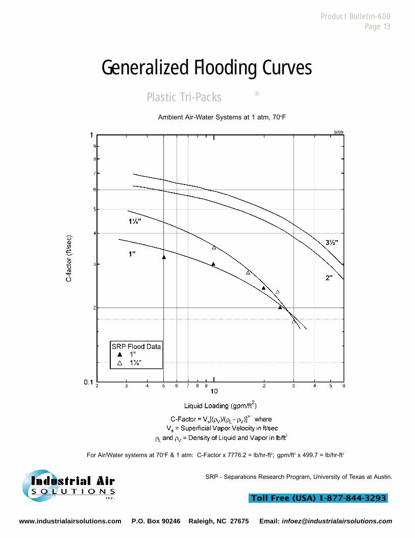
Plastic Tri-Packs ®
Generalized Flooding Curves
Product Bulletin-600Page 13
Ambient Air-Water Systems at 1 atm, 70oF
For Air/Water systems at 70oF & 1 atm: C-Factor x 7776.2 = lb/hr-ft2; gpm/ft2 x 499.7 = lb/hr-ft2
SRP - Separations Research Program, University of Texas at Austin.
9/99
www.industrialairsolutions.com P.O. Box 90246 Raleigh, NC 27675 Email: [email protected]
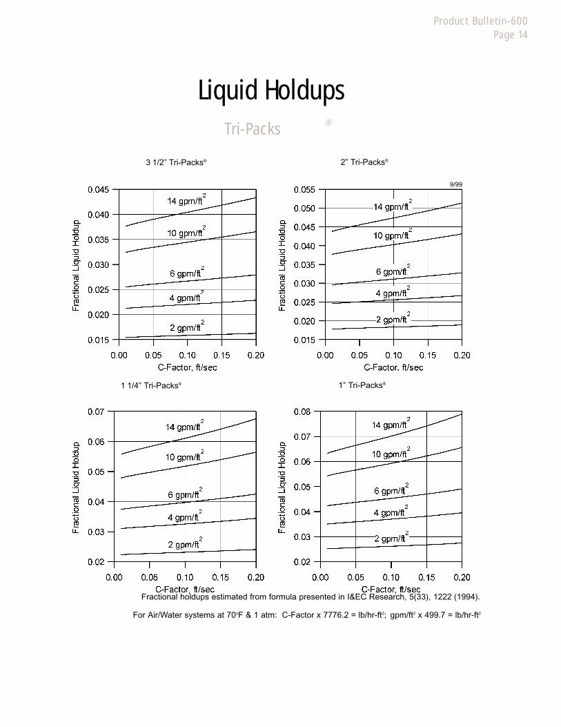
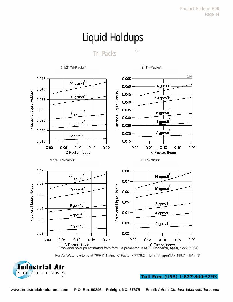
Tri-Packs ®
Liquid Holdups
Product Bulletin-600Page 14
For Air/Water systems at 70oF & 1 atm: C-Factor x 7776.2 = lb/hr-ft2; gpm/ft2 x 499.7 = lb/hr-ft2
Fractional holdups estimated from formula presented in I&EC Research, 5(33), 1222 (1994).
9/99
3 1/2” Tri-Packs® 2” Tri-Packs®
1” Tri-Packs®1 1/4” Tri-Packs®
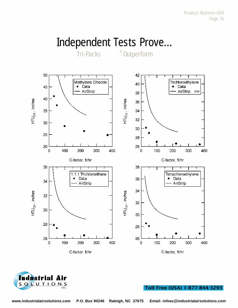
Independent Tests Prove...Tri-Packs ®
Outperform
Product Bulletin-600Page 15
9/99
www.industrialairsolutions.com P.O. Box 90246 Raleigh, NC 27675 Email: [email protected]

1611 Peachleaf St., Houston, Texas 77039 800-678-0345 Phone: 281-449-9500 Fax: 281-449-9400 www.jaeger.com
2” Jaeger Tri-Packs® performance data taken from U.S. Department of Commerce document AD-A 158 811, June 1985.AirStrip v.1.2 is a computer program which uses the mass transfer correlations of Onda et al., to design and rate air strippers.
JAEGER
Product Bulletin-600Page 16
9/99
Tri-Packs Exceed Expectations
AirStrip® Predictions
Tri-Packs ®
Liquid Holdups
Product Bulletin-600Page 14
For Air/Water systems at 70oF & 1 atm: C-Factor x 7776.2 = lb/hr-ft2; gpm/ft2 x 499.7 = lb/hr-ft2
Fractional holdups estimated from formula presented in I&EC Research, 5(33), 1222 (1994).
9/99
3 1/2” Tri-Packs® 2” Tri-Packs®
1” Tri-Packs®1 1/4” Tri-Packs®
www.industrialairsolutions.com P.O. Box 90246 Raleigh, NC 27675 Email: [email protected]
G(lb/hr-ft2)
Temp.(oF) 2
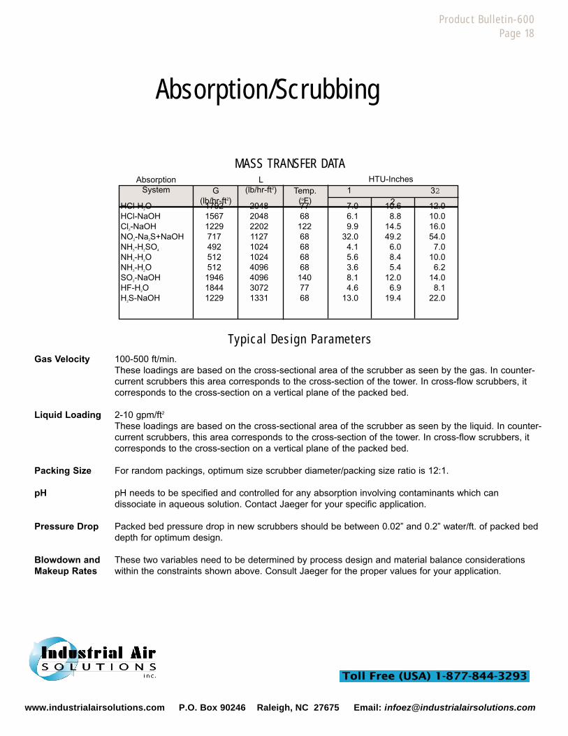
Absorption/Scrubbing
Product Bulletin-600Page 18
Typical Design Parameters
Gas Velocity 100-500 ft/min.These loadings are based on the cross-sectional area of the scrubber as seen by the gas. In counter-current scrubbers this area corresponds to the cross-section of the tower. In cross-flow scrubbers, itcorresponds to the cross-section on a vertical plane of the packed bed.
Liquid Loading 2-10 gpm/ft2
These loadings are based on the cross-sectional area of the scrubber as seen by the liquid. In counter-current scrubbers, this area corresponds to the cross-section of the tower. In cross-flow scrubbers, itcorresponds to the cross-section on a vertical plane of the packed bed.
Packing Size For random packings, optimum size scrubber diameter/packing size ratio is 12:1.
pH pH needs to be specified and controlled for any absorption involving contaminants which can dissociate in aqueous solution. Contact Jaeger for your specific application.
Pressure Drop Packed bed pressure drop in new scrubbers should be between 0.02” and 0.2” water/ft. of packed bed depth for optimum design.
Blowdown and These two variables need to be determined by process design and material balance considerationsMakeup Rates within the constraints shown above. Consult Jaeger for the proper values for your application.
AbsorptionSystem
MASS TRANSFER DATAL
(lb/hr-ft2) 1 32HTU-Inches
HCl-H2O 1792 2048 77 7.0 10.6 12.0HCl-NaOH 1567 2048 68 6.1 8.8 10.0Cl2-NaOH 1229 2202 122 9.9 14.5 16.0NO2-Na2S+NaOH 717 1127 68 32.0 49.2 54.0NH3-H2SO4 492 1024 68 4.1 6.0 7.0NH3-H2O 512 1024 68 5.6 8.4 10.0NH3-H2O 512 4096 68 3.6 5.4 6.2SO2-NaOH 1946 4096 140 8.1 12.0 14.0HF-H2O 1844 3072 77 4.6 6.9 8.1H2S-NaOH 1229 1331 68 13.0 19.4 22.0
www.industrialairsolutions.com P.O. Box 90246 Raleigh, NC 27675 Email: [email protected]
Product Bulletin-600Page 19
Among the biggest long term maintenance problems facing personnel charged withoperating scrubbers and strippers are scaling, fouling, and disinfection. Scaling is theprecipitation and deposition of water-insoluble salts onto column internals and pack-ing. Scaling is distinct from fouling, which involves the formation of deposits other thansalts and which may be due to corrosion or biological growth. Finally, operators mustconsider disinfection if the water being treated is ultimately destined for human or ani-mal consumption.
Scaling is especially troublesome when the contaminant being dealt with can dissoci-ate or needs to dissociate in water to effect its efficient removal. For these contami-nants, water pH is adjusted by adding strong acids or bases to prevent or enhancedissociation. Generally speaking, dissociation needs to be prevented when the contaminant is to be stripped from water;it needs to be enhanced when the contaminant is to be scrubbed from air. Unfortunately, when these pH adjustmentsare performed on “hard” water, one is often forced to cross the solubility envelopes for sparingly soluble salts of calci-um, iron, or magnesium (among others). If these solubility phase boundaries are crossed, precipitation is a thermody-namic inevitability. Contrary to popular belief, packing geometry plays little or norole in the scaling process. The rate at which a packing scales, therefore, dependsprimarily upon the initial water “hardness” and the “pH driving force”, i.e. the differencebetween the operating pH and the pH at the solubility limit for the salt in question, withsecondary effects caused by liquid and gas loading.
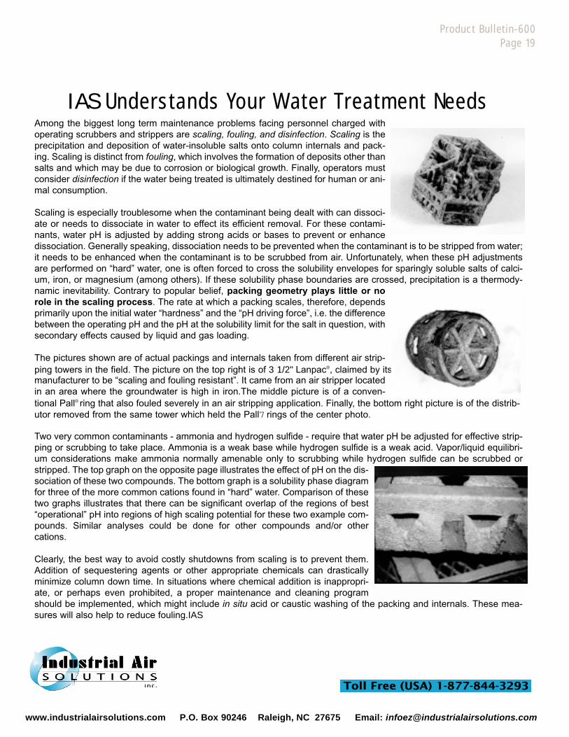
The pictures shown are of actual packings and internals taken from different air strip-ping towers in the field. The picture on the top right is of 3 1/2" Lanpac®, claimed by itsmanufacturer to be “scaling and fouling resistant”. It came from an air stripper locatedin an area where the groundwater is high in iron.The middle picture is of a conven-tional Pall® ring that also fouled severely in an air stripping application. Finally, the bottom right picture is of the distrib-utor removed from the same tower which held the Pall7 rings of the center photo.
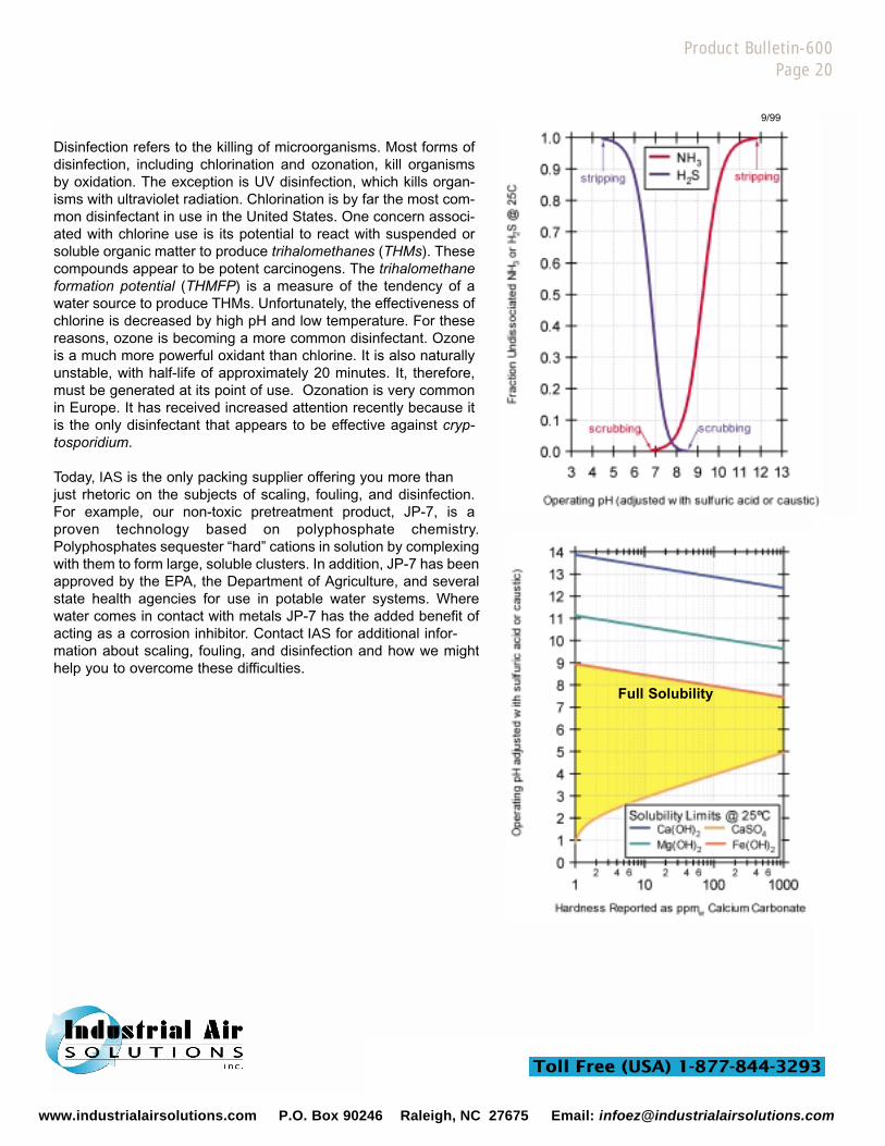
Two very common contaminants - ammonia and hydrogen sulfide - require that water pH be adjusted for effective strip-ping or scrubbing to take place. Ammonia is a weak base while hydrogen sulfide is a weak acid. Vapor/liquid equilibri-um considerations make ammonia normally amenable only to scrubbing while hydrogen sulfide can be scrubbed orstripped. The top graph on the opposite page illustrates the effect of pH on the dis-sociation of these two compounds. The bottom graph is a solubility phase diagramfor three of the more common cations found in “hard” water. Comparison of thesetwo graphs illustrates that there can be significant overlap of the regions of best“operational” pH into regions of high scaling potential for these two example com-pounds. Similar analyses could be done for other compounds and/or othercations.
Clearly, the best way to avoid costly shutdowns from scaling is to prevent them.Addition of sequestering agents or other appropriate chemicals can drasticallyminimize column down time. In situations where chemical addition is inappropri-ate, or perhaps even prohibited, a proper maintenance and cleaning programshould be implemented, which might include in situ acid or caustic washing of the packing and internals. These mea-sures will also help to reduce fouling.IAS
IAS Understands Your Water Treatment Needs
www.industrialairsolutions.com P.O. Box 90246 Raleigh, NC 27675 Email: [email protected]
Product Bulletin-600Page 20
Disinfection refers to the killing of microorganisms. Most forms ofdisinfection, including chlorination and ozonation, kill organismsby oxidation. The exception is UV disinfection, which kills organ-isms with ultraviolet radiation. Chlorination is by far the most com-mon disinfectant in use in the United States. One concern associ-ated with chlorine use is its potential to react with suspended orsoluble organic matter to produce trihalomethanes (THMs). Thesecompounds appear to be potent carcinogens. The trihalomethaneformation potential (THMFP) is a measure of the tendency of awater source to produce THMs. Unfortunately, the effectiveness ofchlorine is decreased by high pH and low temperature. For thesereasons, ozone is becoming a more common disinfectant. Ozoneis a much more powerful oxidant than chlorine. It is also naturallyunstable, with half-life of approximately 20 minutes. It, therefore,must be generated at its point of use. Ozonation is very commonin Europe. It has received increased attention recently because itis the only disinfectant that appears to be effective against cryp-tosporidium.
Today, IAS is the only packing supplier offering you more thanjust rhetoric on the subjects of scaling, fouling, and disinfection.For example, our non-toxic pretreatment product, JP-7, is aproven technology based on polyphosphate chemistry.Polyphosphates sequester “hard” cations in solution by complexingwith them to form large, soluble clusters. In addition, JP-7 has beenapproved by the EPA, the Department of Agriculture, and severalstate health agencies for use in potable water systems. Wherewater comes in contact with metals JP-7 has the added benefit ofacting as a corrosion inhibitor. Contact IAS for additional infor-mation about scaling, fouling, and disinfection and how we mighthelp you to overcome these difficulties.
Full Solubility
9/99
www.industrialairsolutions.com P.O. Box 90246 Raleigh, NC 27675 Email: [email protected]
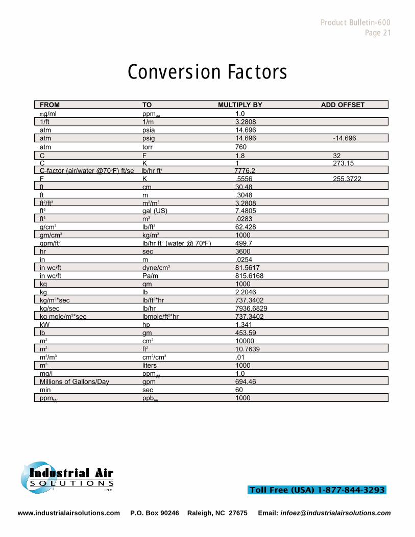
Conversion Factors
Product Bulletin-600Page 21
FROM TO MULTIPLY BY ADD OFFSETmg/ml ppmW 1.01/ft 1/m 3.2808atm psia 14.696atm psig 14.696 -14.696atm torr 760C F 1.8 32C K 1 273.15C-factor (air/water @70oF) ft/se lb/hr ft2 7776.2F K .5556 255.3722ft cm 30.48ft m .3048ft2/ft3 m2/m3 3.2808ft3 gal (US) 7.4805ft3 m3 .0283g/cm3 lb/ft3 62.428gm/cm3 kg/m3 1000gpm/ft2 lb/hr ft2 (water @ 70oF) 499.7hr sec 3600in m .0254in wc/ft dyne/cm3 81.5617in wc/ft Pa/m 815.6168kg gm 1000kg lb 2.2046kg/m2*sec lb/ft2*hr 737.3402kg/sec lb/hr 7936.6829kg mole/m2*sec lbmole/ft2*hr 737.3402kW hp 1.341lb gm 453.59m2 cm2 10000m2 ft2 10.7639m2/m3 cm2/cm3 .01m3 liters 1000mg/l ppmW 1.0Millions of Gallons/Day gpm 694.46min sec 60ppmW ppbW 1000
www.industrialairsolutions.com P.O. Box 90246 Raleigh, NC 27675 Email: [email protected]
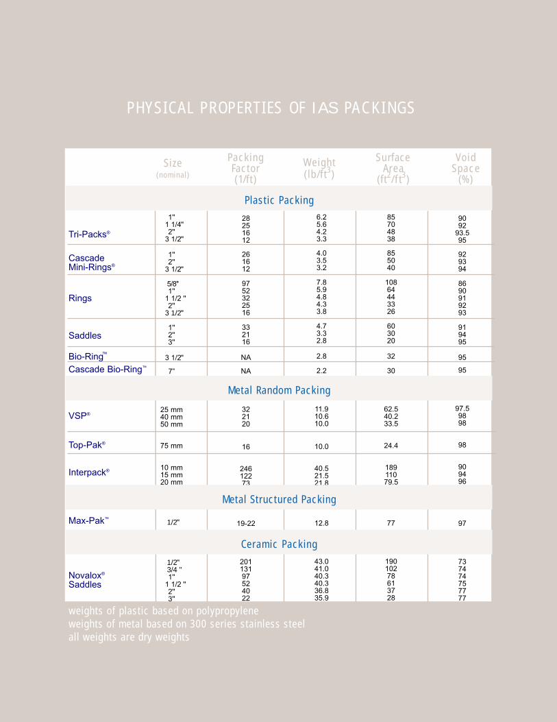
PHYS ICAL PROPERT I ES OF I A S PA C K I N G S
Type Size(nominal)
PackingFactor(1/ft)
Weight(lb/ft3)
Surface Area
(ft2/ f t3)
VoidSpace
(%)
Tri-Packs®
CascadeMini-Rings®
Rings
Saddles
™Bio-RingCascade Bio-Ring™
VSP®
Top-Pak®
Interpack®
Max-Pak™
Novalox®
Saddles
1''1 1/4 ''2''
3 1/2 ''
1''2''
3 1/2 ''
5/8''1''
1 1/2 ''2''
3 1/2 ''
1''2''3''
3 1/2 ''
7”
25 mm40 mm50 mm
75 mm
10 mm15 mm20 mm
1/2 ''
1/2 ''3/4 ''1''
1 1/2 ''2''3''
28251612
261612
9752322516
332116
NA
NA
322120
16
24612273
19-22
20113197524022
6.25.64.23.3
4.03.53.2
7.85.94.84.33.8
4.73.32.8
2.8
2.2
11.910.610.0
10.0
40.521.521.8
12.8
43.041.040.340.336.835.9
85704838
855040
10864443326
603020
32
30
62.540.233.5
24.4
18911079.5
77
19010278613728
9092
93.595
929394
8690919293
919495
95
95
97.59898
98
909496
97
737474757777
Metal Random Packing
Ceramic Packing
Plastic Packing
weights of plastic based on polypropyleneweights of metal based on 300 series stainless steelall weights are dry weights
Metal Structured Packing
For More Information:
General BrochureSeries 100
Metal VSP® & Metal Top-Pak®
Series 200
Metal Random PackingSeries 300 - Future Publication
CoFloTM TraysSeries 400
Fractionation TraysSeries 450 - Future Publication
Metal Max-PakTM
Series 500
Plastic Tri-Packs®
Series 600
Plastic Rings & SaddlesSeries 700
Plastic Cascade Mini-Rings®
Series 800
Biological Products & ChemicalsSeries 900 - Future Publication
Ceramic PackingSeries 1000
Column InternalsSeries 1100
-- Complete Technical Catolog includes all of the above along with othertechnical and performance information.
NOTE: The information presented in this brochure is believed to beaccurate and reliable. However, it is based on test results which maynot apply to your application. Therefore, the data is presented withoutguarantee or warranty. We recommend that you contact IAS’s engi-neering department or your local representative to discuss the details ofyour specific application.
TRI-PACKS®
Patent No. 4,203,935. Canadian Patent No. 1,150,621. Tri-Packs havethe Trademark “HACKETTEN” in Germany. Further Patents Pending.
VSP®, TOP-PAK®, Novalox® are trademarks of VFF, Germany.
Other Trademarks herein:CorzanTM B.F. GoodrichNoryl® General Electric CompanyKynar® Elf Atochem North America, Inc.Halar® Ausimont USA, Inc.Tefzel® E.I. DuPont de Nemours & Co., Inc.Teflon® E.I. DuPont de Nemours & Co., Inc.Intalox® Norton Chemical Process ProductsPall® Norton Chemical Process ProductsRaschig® Raschig AGTellerette® Ceilcote-Air Pollution ControlHiflow Rings® Rauschert Industries, Inc.Lanpac® Lantec Products, Inc.NSF® NSF International
Superior performance by designTM
600-1099-10000
www.industrialairsolutions.com P.O. Box 90246 Raleigh, NC 27675 Email: [email protected]