tribology and superhydrophobicity of laser-controlled-melted alumina surfaces with hard particles
TRANSCRIPT

Tribology and Superhydrophobicity of Laser-Controlled-MeltedAlumina Surfaces with Hard Particles
BEKIR SAMI YILBAS,1 BHARAT BHUSHAN,1,2,3 B.J. ABDUL ALEEM,1
and ZUHAIR GASEEM1
1.—Department of Mechanical Engineering, King Fahd University of Petroleum & Minerals,Dhahran 31261, Saudi Arabia. 2.—Nanoprobe Laboratory for Bio- and Nanotechnology andBiomimetics, The Ohio State University, 201 W. 19th Ave, Columbus, OH 43210-1142, USA.3.—e-mail: [email protected]
Laser-controlled melting of alumina surface with a carbon film of about 40-lmthickness formed prior to the laser treatment process is carried out to improveits hardness, durability, and superhydrophocity. The carbon film consisted of auniformly distributed mixture of hard particles of WC, SiC, and B4C. Thepresence of carbon film improves the absorption of the laser beam during thetreatment process. The morphology and hydrophobicity of the laser-treatedsurface were evaluated using optical microscopy, atomic force microscopy, andthe contact angle measurement, respectively. The chemical changes of thetreated layer were examined using scanning electron microscopy and energy-dispersive spectroscopy. The structure of the nitride compound formed at thesurface was characterized using x-ray diffraction, which was also used todetermine the residual stress at the surface. Both microhardness and fracturetoughness of the laser-treated surface were determined using indentationtests. Scratch tests were conducted to measure the friction coefficient andscratch resistance of the laser-treated surface. Laser treatment produces mi-cropoles, nanopoles, and small size cavities at the surface, which enhancehydrophobicity of the surface. The microhardness of the laser-treated surfaceincreases almost 50% because of the dense layer formed at the surface and theresidual stress is in the order of �2 GPa, which is compressive. The scratchresistance and friction coefficient of the laser-treated surface is superior.
INTRODUCTION
Alumina is widely used in industry because it canwithstand high temperatures, resists corrosion, andcan be used in wear environments.1–3 Alumina tilesare normally made by compacting and hot pressingalumina powders or granules. Because the aluminaparticles and granules have a high melting temper-ature and high hardness, in general, poles are formedwithin the tile structure after its formation, whichlimits the practical applications of alumina tiles,particularly in surface engineering. One of themethods that can be used to minimize the porestructures in alumina tiles is to introduce controlledmelting at the surface. High-power laser melting hasseveral advantages over the conventional meltingtechniques for surface melting because of its preci-sion of operation, fast processing time, and low cost.
In high-power laser melting, care must be taken toavoid excessive thermal stresses in the treated layerbecause of the high-temperature gradient across theliquid and solid phases owing to the low thermalconductivity of alumina; therefore, controlled melt-ing minimizing the stress levels in the treated layer isessential despite the several advantages of lasermelting. On the other hand, high cooling rates at thesurface result in the formation of fine grains and adense layer, which, in turn, enhances the microh-ardness of the surface. In addition, surface prepara-tion prior to the laser treatment improves the surfacecharacteristics such as hardness.4 In this case,forming a fine carbon film of low thickness comprisingof hard particles, such as carbides, further improvesthe microhardness of the surface.5
A considerable amount of research has been con-ducted to examine the laser treatment of alumina
JOM, Vol. 66, No. 6, 2014
DOI: 10.1007/s11837-014-0971-6� 2014 The Minerals, Metals & Materials Society
1068 (Published online April 29, 2014)

surfaces. Harimkar and Dahotre6 studied the sur-face characteristics of a laser-modified aluminaceramic and examined the microstructure evolutionin terms of the development of crystallographic andmorphological (size and shape) textures of surfacegrains as a function of laser processing parameters.Krishnan et al.7 studied laser surface modificationand characterization of air-plasma-sprayed aluminacoatings. They showed that Raman spectroscopyreveals the restoration of an a-Al2O3 phase anddemonstrated that the scattering technique could beused to optimize the processing parameters to ob-tain a superior surface finish. Yu et al.8 examinedthe laser surface characteristics of alumina ceram-ics in vacuum and demonstrated that continuousline-like holes were formed at alumina surfacesafter the laser treatment process; however, properselection of laser treatment parameters could resultin regular microscopic patterns exhibiting improvedelectrical properties at the surface.
Yilbas et al.9 studied laser surface texturing ofalumina for improved hydrophobicity and foundthat laser-controlled ablation resulted in microtex-turing and nanotexturing of the surface. Althoughthe surface texture did not follow a regular pattern,it consisted of pillars and dimple-like structures,and the surface roughness was within the sub-microscale. Yilbas et al.10 also studied laser carbo-nitriding of the alumina surface, and the resultsshow that the formation of Al (C, N) in the surfaceregion enhanced the microhardness at the surface.Adraider et al.11 examined the surface modificationof stainless steel by laser-induced deposition of analumina ceramic coating. They showed that laserirradiation of dry alumina films led to the depositionof a crystalline alumina coating in the a-Al2O3 formon the substrate surface, which significantlyimproved the mechanical properties of the alumina-coated surface. Yilbas et al.12 demonstrated thatlaser gas-assisted nitriding of alumina surfacesdevelops two regions in the laser irradiated zone; adense layer composed of a-Al2O3 and AlN wasformed in the surface region and a randomlystacked lamellae structure was observed below thesurface region.
Carrado et al.13 showed that pulsed laser deposi-tion of alumina coatings form stoichiometric andpartially crystallized films with an amorphous ma-trix. Decup et al.14 studied the laser surface treat-ment of alumina and measured the dielectricstrength of the resulting surface, and they foundthat the dielectric strength was not significantlyaffected by the laser-induced surface modifications.Triantafyllidis et al.15 used two combined lasersources for laser surface treatment of alumina-based ceramics to control the thermal gradients andcooling rates during the processing so that crackformation could be eliminated or minimized. In astudy of the laser surface treatment of plasma-sprayed alumina coatings, Ibrahim et al.16 showedthat laser fluence played a major role in modifying
the surface morphology of the coating, followed bythe pulse repetition rate. Yilbas5 investigated lasergas-assisted melting of a preprepared alumina sur-face containing TiC particles at the surface, andthey found that a dense structure containingundissolved TiC particles formed in the surface re-gion of the laser-treated layer, whereas a columnarstructure formed beneath the dense structure.
Wallstabe17 studied laser-assisted surface modi-fication of alumina and its tribological behavior, andit was demonstrated that multiphase ceramics form,which possessed a higher wear resistance than themonolithic ones. Dupas-Bruzek et al.18 showed thatlaser surface structural transformation products ofsintered alumina were composed of an amorphousmatrix and cement; in addition, the starting mate-rial at grain boundaries played an important role inthe formation of the new amorphous material. Scitiet al.19 investigated laser-induced microstructuralchanges of alumina, and they showed that at highfluence, the material was removed by decomposi-tion/vaporization and the depth of material removalwas linearly dependent on the number of pulses.Using process optimization of laser surface struc-turing of alumina, Samant et al.20 demonstratedthat the pulse repetition rate was the most signifi-cant factor affecting the minimization of the inter-dendritic porosity, whereas the scanning speedplayed a vital role in increasing the grain size.Yilbas et al.21 investigated laser controlled meltingof alumina surfaces containing B4C particles, andfound that microhardness of the surface increasedsignificantly after the laser treatment process,which was attributed to high cooling rates and theformation of nitride species at the surface. In addi-tion, they found that the residual stress generated iscompressive and micro or major cracks are not ob-served at the laser-treated surface. Khalil et al.22
characterized surface-modified alumina ceramicsand demonstrated that the laser-treated surface iscomposed of a multiphase surface structure, with adense layer containing fine grains formed at thesurface. Yilbas et al.23 studied laser-controlledmelting of alumina surfaces and thermal stressanalysis, they and showed that the residual stresspredicted agreed with the measured values andhigh heating and cooling rates resulted in high vonMises stress levels in the surface region. Moncayoet al.24 demonstrated that, by controlling the laserenergy density in laser surface modification of alu-mina, more multifaceted grains and a laser-treatedlayer of lower porosity can be formed.
Although laser surface treatment of alumina andparticle injection into thetreated layerhasbeenstudiedpreviously,5,9,10,21 the effect of a mixture of carbideparticles, in the melted zone, on the laser-treated sur-face characteristics has not been investigated. There-fore, in the current study, laser-controlled melting of aalumina surface with a carbon film of 40 lm thickness,in which carbide particles based on WC, SiC, and B4Care uniformly distributed, is formed on the alumina
Tribology and Superhydrophobicity of Laser-Controlled-Melted Alumina Surfaces with Hard Particles 1069

surface prior to the laser-treatment process. The mor-phological, hydrophobicity, material properties, andwear characteristics of the laser-treated surface wereexamined using various analytical tools. The results ofthe study are the subject of this article.
EXPERIMENTAL PROCEDURES
The CO2 laser (LC-ALPHAIII, http://www.amada.co.uk/, 2014) delivering a nominal output power of2 kW was used to irradiate the workpiece surface.The nominal focal length of the focusing lens was127 mm and the diameter of the laser beam focusedat the workpiece surface was �0.3 mm. The nitro-gen gas used as the assisting gas was applied co-axially with the laser beam using a conical nozzle,and the laser treatment was repeated several timesusing different laser parameters. Laser parametersresulting in controlled melting of the surface with aminimum of surface defects, such as very smallcavities without crack networks, were selected andthe laser treatment conditions are given in Table I.
Alumina (Al2O3) tiles (Ceram Tec-ETEC, 2010,http://www.army-technology.com/contractors/ballistic_protection/ceram-etec/, 2014) with 3 mm thicknesswere used as the workpieces. A water-soluble phe-nolic resin and 5 wt.% of SiC, 5 wt.% of WC, and5 wt.% of B4C powders of about 400 nm particle si-zes were mixed until the mixture was homogeneousprior to applying it uniformly to the workpiecesurface. To form an approximately 40-lm thick filmat the alumina tile surface, the samples were placedin a control chamber, which was at 8 bar pressureand 175�C for 2 h. The workpieces were then heatedto 400�C in an argon environment for 6 h to ensurethe conversion of the phenolic resin into a carbonfilm. The presence of the carbon film improves theabsorption of the laser beam during the treatmentprocess. The sample surfaces were scanned using alaser beam with the parameters given in Table I.
Material characterization of the laser-treatedsurfaces was conducted using an optical microscope,scanning electron microscopy (SEM), energy-dispersive spectroscopy (EDS), and x-ray diffraction(XRD). A JEOL 6460 scanning electron microscope(JEOL Ltd., Tokyo, Japan) was used for SEMexaminations and a Bruker D8 Advanced x-raydiffractometer using CuKa radiation (Bruker OpticsInc., Billerica, MA, http://www.bruker.com/products/x-ray-diffraction-and-elemental-analysis/x-ray-diffraction.html, 2014) was used for XRD analysis.Typical settings of the XRD were 40 kV and 30 mA
with the scanning angle (2h) ranging from 20� to80�. The surface roughness measurement of the la-ser-melted surfaces was performed using an Agilent5100 AFM in the contact mode (Agilent Technolo-gies, Santa Clara, CA). The tip was made of siliconnitride probes (r = 20–60 nm) with a manufacturer-specified force constant k of 0.12 N/m.
A Microphotonics digital microhardness tester(MP-100TC, http://www.innovatest-europe.com/,2014) was used to determine the microhardness atthe surface. The standard test method for Vickersindentation hardness of advanced ceramics (ASTMC1327-99) was adopted. Microhardness was mea-sured at the surface of the workpiece after the lasertreatment process, and the measurements were re-peated five times at each location to determine theconsistency of the results.
A linear microscratch tester (MCTX-S/N:01-04300, http://www.csm-instruments.com/, 2014)was used to determine the wear characteristics andfriction coefficient of the laser-treated and un-treated surfaces. The equipment was set at a con-tact load ranging from 0.03 N to 5 N. The scanningspeed was 5 mm/min with a loading rate of 5 N/sand the total length for the scratch tests was 5 mm.
The wetting experiment was performed using aKyowa (model DM 501, http://www.face-kyowa.co.jp/english/en_products/en_contact_angle/, 2014) con-tact angle goniometer. The static sessile drop methodwas adopted for the contact angle measurement. Thewater contact angle between a water droplet and theheat-treated surface was measured with deionizedwater used as the fluid medium. The droplet volumewas controlled with an automatic dispensing systemhaving a volume step resolution of 0.1 lL. Still ima-ges were captured, and the contact angle measure-ments were performed with 1 s duration of depositionof a water droplet on the surface.
The XRD technique was used to measure theresidual stresses in the surface region of the laser-treated layer. The XRD technique provides data inthe surface region of the specimens due to the lowpenetration depth of Cu-Ka radiation into the trea-ted layer; i.e., the penetration depth was in the or-der of 5 lm. The measurements relied on thestresses in the fine-grained polycrystalline struc-ture and the position of the diffraction peaksexhibited a shift as the specimen was rotated by anangle w. The magnitude of the shift can be related tothe magnitude of the residual stress. The relation-ship between the peak shift and the residual stress(r) is given as:25
Table I. Laser heating conditions used in the experiment
Scanningspeed (cm/s)
(mm/min)Peak power
(W)Frequency
(Hz)Nozzle gap
(mm)
Nozzlediameter
(mm)
Focussetting(mm)
N2 pressure(kPa)
10 2000 1500 1.5 1.5 127 600
Yilbas, Bhushan, Abdul Aleem, and Gaseem1070

r ¼ E
ð1þ tÞSin2w
ðdn � doÞdo
(1)
where E is Young’s modulus, m is Poisson’s ratio, w isthe tilt angle, and dn are the d spacing measured ateach tilt angle. If shear strains are not present inthe specimen, then the d spacing changes linearlywith sin2w. Figure 1 shows the linear dependence ofd(311) on sin2w in the region of the laser-cut sur-face. The c-Al2O3 peak (ICDD 29-1486) is at 37.5�,which corresponds to the (311) plane with aninterplanar spacing of 0.239 nm. The linear depen-dence of d(311) has a slope of �1.60 9 10�12 m/de-grees and an intercept of 0.239 nm as shown inFig. 1. The residual stress determined by the XRDtechnique in the vicinity of the surface is on theorder of �2.0 ± 0.06 GPa. The XRD measurementswere repeated three times, and the error of mea-surement is in the order of 3%.
The fracture toughness of the surface was deter-mined using the indenter test data for microhard-ness (Vickers) and crack inhibiting. In this case,microhardness in HV and the crack lengths gener-ated due to indentation at the surface were mea-sured. The length (l) measured corresponds to thedistance from the crack tip to the indent. The cracklengths were individually summed to obtain
Pl as
described in a previous study.26 The crack length cfrom the center of the indent was the sum of indi-vidual crack lengths (
Pl) and half of the diagonal
length of the indent 2a. Therefore, c = a +P
l.However, depending on the ratio of c
a, the average ofequations was developed to estimate the fracturetoughness (K). However, the equation proposed byAnstis et al.27 has limitations due to nonlinearity ofthe coefficients for values of c
a > 2, which is notapplicable for tungsten carbide (�2.5 to 4.5).Therefore, the equation proposed by Evans andCharles28 was used to determine the fracturetoughness (Kc), which is applicable for0:6 � c
a � 4:5� �
, i.e.,
Kc ¼ 0:079P
a
� �1:5
� log 4:5Pa
c
� �(2)
where P is the applied load on the indenter, c is thecrack length, and a is half of the diagonal length ofthe indent. Table II gives the data used for thefracture toughness calculations.
RESULTS AND DISCUSSION
Laser-controlled melting of an alumina tile sur-face with a carbon film of about 40 lm thickness,which hosts the hard particles was conducted, andthe material and wear characteristics of the treatedsurface were determined using SEM, EDS, andXRD. The surface hydrophobicity and morphologywere investigated using contact angle measurementand atomic force microscopy (AFM). Residual stressin the surface region was measured using the XRDdata, whereas the fraction toughness of the surfacewas determined from the indentation tests.
Surface Morphology and Contact AngleMeasurement
Figures 2 and 3 show optical micrographs, andscanning electron micrographs, and AFM images ofthe laser-treated workpiece, respectively. Regularlaser scanning tracks are observed in the opticalimages of the surface, which are associated with therepetitive pulsations during laser scanning (Fig. 2aand b). As the laser scans the surface at a constantspeed with a laser pulse repetition rate of 1500 Hz,regular laser scanning tracks consisting of over-lapped irradiated spots are formed (Fig. 2d). Theoverlapping ratio of the laser spots is estimated tobe about 75% at the surface, and laser-controlledmelting does not result in the overflow of moltenmaterial in between the laser scanning tracks at thesurface. In addition, large-scale asperities such aslarge voids and large cavities are not observed at thesurface. Large cavities are formed because of abla-tion (large-scale evaporation) at the surface; how-ever, through controlled melting, surfaceevaporation is localized to shallow depths and smallareas during laser scanning. A close examination ofthe laser-treated surface reveals that partiallyembedded hard particles are at the surface (Fig. 2c),which is attributed to the high melting temperature
Table II. Fracture toughness and data used forfracture toughness calculations
Fracturetoughness(MPa
ffiffiffiffiffimp
) P (N) a (lm) c (lm)
As-received surface 3.5 ± 0.2 5 45 60Laser-treated surface 3.0 ± 0.4 5 45 95
Fig. 1. Linear dependence of d(311) on sin2w.
Tribology and Superhydrophobicity of Laser-Controlled-Melted Alumina Surfaces with Hard Particles 1071

of the hard particles (B4C, SiC, and WC), allowingthem to stay in the solid phase.
However, a few scattered microcracks are ob-served at the surface (Fig. 2f) due to one or both ofthe following: (I) high cooling rates at the surfacecausing excessive temperature gradients at thesurface, which in turn forms thermally inducedmicrocracks at the surface, and (II) the mismatchbetween the thermal expansion coefficients of alu-mina (base material) and the hard particles gener-ating thermally induced microstrains near the hardparticles, which in turn forms microcracks on thelaser-treated surface in the vicinity of the hardparticles. Moreover, the high cooling rates resultin grain refining at the surface, which can also be
observed in the SEM images. Although the differ-ences in thermal expansion coefficients of the hardparticles contribute to the microstress levels whileinfluencing microcrack distribution at the surface,large-scale cracks are not observed at the surface.This occurs because of the stress relaxation throughthe development few microcracks at the surface andthe self-annealing of scanned laser tracks by sub-sequent laser scanning. In this case, the coolingrate, in particular below the surface, is influencedby the gradual heating and cooling due to laserscanning, which lowers the temperature gradientsand suppresses the thermal stress levels below thesurface of the laser-treated area. However, localizedevaporation results in a fine surface texture composed
Fig. 2. Optical and SEM micrographs of the laser-treated surface: (a) optical image of laser-treated alumina tile, (b) optical image of laser scantracks, (c) SEM micrograph partially immersed hard particles, (d) SEM micrograph of overlapping of laser irradiated spots at the surface, (e) SEMmicrograph of small void at the surface, and (f) SEM micrograph of microcrack at the surface.
Yilbas, Bhushan, Abdul Aleem, and Gaseem1072

of nanosized poles and fiber-like structures at thesurface, which are visible in the SEM images(Fig. 2e) and AFM micrographs (Fig. 3). As theirradiating laser beam has a high frequency, laserspots overlap along the laser scanning tracks.However, the molten metal in small cavities at thesurface, formed by laser scanning, flows into smallcavities newly formed during subsequent laserpulses. This, in turn lowers the cavity depth andalters the geometric features at the irradiated sur-face, significantly lowering the surface roughness(Ra = 0.56 lm) when compared to that reported in aprevious study (Ra = 2.5 lm).18 AFM micrographsshow that the topological features of the structuresresemble those of the lotus leaf surface.29,30
The hydrophobicity of solid surfaces can be as-sessed through contact angle measurements. The
contact angle of a liquid on a perfectly smooth andchemically homogenous solid surface can be formu-lated by Young’s equation:29
cosh ¼ ðcsv � cslÞclv
(3)
whereh is the contact angle, csv is the interfacialtension of the solid–vapor interface, csl is theinterfacial tension of the solid–liquid interface, andclv is the interfacial tension of liquid–vapor inter-face. The practical application of Young’s equationis limited because the surfaces are rough andchemically heterogeneous. Wenzel31 and Cassie andBaxter32 proposed a relationship between the con-tact angle of a liquid droplet and the surfaceroughness factor to overcome this limitation. The
Fig. 3. AFM image of the laser-treated surface and surface roughness.
Tribology and Superhydrophobicity of Laser-Controlled-Melted Alumina Surfaces with Hard Particles 1073

Wenzel formulation takes the liquid penetrationinto the rough grooves into account and expressesthe contact angle as follows:31
coshw ¼rðcsv � cslÞ
clv
(4)
wherehw is the rough surface contact angle and r isthe surface roughness factor, which is defined as theratio between the actual and projected surfaceareas, where r = 1 for a perfectly smooth surfaceand r > 1 for a rough surface. The liquid surfaceinterface consists of liquid–solid and liquid–vaporinterfaces, and the contact angle of both interfacesshould be taken into account in the analysis. Thecontact angle equation is expressed as follows:32
coshc ¼ f1cosh1 þ f2cosh2 (5)
where hc is the apparent contact angle, f1 is thesurface fraction of the liquid–solid interface, f2 is thesurface fraction of the liquid–vapor interface, h1 isthe contact angle of the liquid–solid interface, andh2 is the contact angle for liquid–vapor interface. Inthe case of an air–liquid interface, f1 is the solid–liquid fraction, and air fraction (f2) becomes (1 � f1).For f1 = 0, the liquid droplet is not in contact withthe solid surface and for f1 = 1, the droplet com-pletely wets the surface. Moreover, the small con-tact area between the liquid droplet and the solidsurface allows the liquid droplet to roll at the sur-face in the Cassie and Baxter state.32 Figure 4shows optical photographs of the water droplet onthe laser-treated and the untreated surface, andTable III shows the data on the contact angle mea-surements at different locations on the surface ofthe workpiece.
The data in Table III show that the contact anglevaries with the location on the surface. This isattributed to the variation of the surface roughnessand the texture composition of the surface, whichaffects the contact angle.33 In the case of a roughsurface, the water droplet is in a Wenzel state at thesurface as evident from the optical photograph(Fig. 4); in this case, the water droplet penetratesthrough the texture containing high poles and largespacing of the rough surface, which results in a lowcontact angle. However, the Wenzel state is notfrequently observed at the surface; i.e., of 10 tests, itappears only at three locations on the surface. Thecontact angle is considerably higher for the laser-treated samples when compared to that for the un-treated surface. This is attributed to the formationof AlN compound at the surface during the laser-treatment process, the surface free energy for whichis 38.3 mJ/m2 when compared to 68 mJ/m2 forAl2O3.34 The low surface energy (csl) increases thecontact angle for the laser-treated surface, and thefine texture with nanopoles and micropoles enablesair pockets to be accommodated between the waterdroplets and the laser-treated surface. This in turnforms the Cassie and Baxter state at the laser-treated surface, where f in Eq. 3 attains low valuesfor large contact angles (Table III). Therefore, thesurface texture consisting of fine pillars and poles atmicroscale and nanoscale results in both Cassie andBaxter and Wenzel states at the laser-treated sur-face; however, the Cassie and Baxter state covers alarger area at the surface.
Material Examinations
Figure 5 shows SEM micrographs of a cross sec-tion of the laser-treated workpiece. The laser-trea-ted layer has an almost uniform thickness of 40 lmbelow the surface (Fig. 5a) due to the controlledmelting at a constant scanning speed with a steadylaser output power. The dense layer, which isformed at the surface, consists of fine grains andhard particles (Fig. 5b). The dense layer extends
Fig. 4. Images of water droplet shapes on the laser-treated anduntreated surfaces.
Table III. Contact angles measurement resultsprior to and after the laser treatment
Contact angle (�)
Lowroughness
Highroughness
Laser-treated surface 119.7 (+5/–5) 82 (+5/–5)Untreated surface 67.2 (+5/–5)
Yilbas, Bhushan, Abdul Aleem, and Gaseem1074

about 2 lm in the surface region of the laser-treatedlayer. The grain refinement takes place due to thehigh cooling rates at the surface, and the use ofhigh-pressure nitrogen as the assisting gas con-tributes to convection cooling of the surface andformation of AlN compounds at the surface (Fig. 6).The presence of hard particles is evident from theSEM micrographs, and a small microvoid is presentaround each hard particle (Fig. 5c) due to the vol-ume shrinkage and wetting characteristics of thehard particles. In addition, a microcrack is also ob-served in the surface region of the dense layer(Fig. 5d), and these microsize defect sites in thesurface region are caused by the volume shrinkageand microstresses formed in the dense layer. Acrack network is not observed in the dense layer, asthe few microvoids formed stop the crack propaga-tion in the dense layer. However, locally scattered
hard particles influence the micro stress levels inthe dense layer due to the mismatch between thethermal expansion coefficients. Large-scale cracksare not observed across the laser-treated layer dueto the self-annealing effect of the scanned lasertracks by subsequent laser scanning. The heatconduction from the newly formed tracks sup-presses the cooling rate of the previously formedscanning tracks. The columnar-like stacked struc-tures are observed because of gradual cooling of thesolid phase in this region (Fig. 5d). As the depthbelow the surface increases, a heat-affected zone isformed, and due to the low thermal diffusivity of thesubstrate material, the extension of the heat-af-fected zone into the solid bulk is suppressed(Fig. 5e).
Figure 6 shows x-ray diffractograms for the laser-treated and as-received surfaces, and the presence
Fig. 5. SEM micrographs of a cross section of the laser-treated layer and untreated workpiece: (a) SEM micrograph of laser-treated layer crosssection, (b) SEM micrograph of hard particles in the dense layer, (c) SEM image of void and hard particle in the dense layer, (d) SEM image oflaser-treated region below the dense layer, and (e) SEM image of untreated workpiece cross section.
Tribology and Superhydrophobicity of Laser-Controlled-Melted Alumina Surfaces with Hard Particles 1075
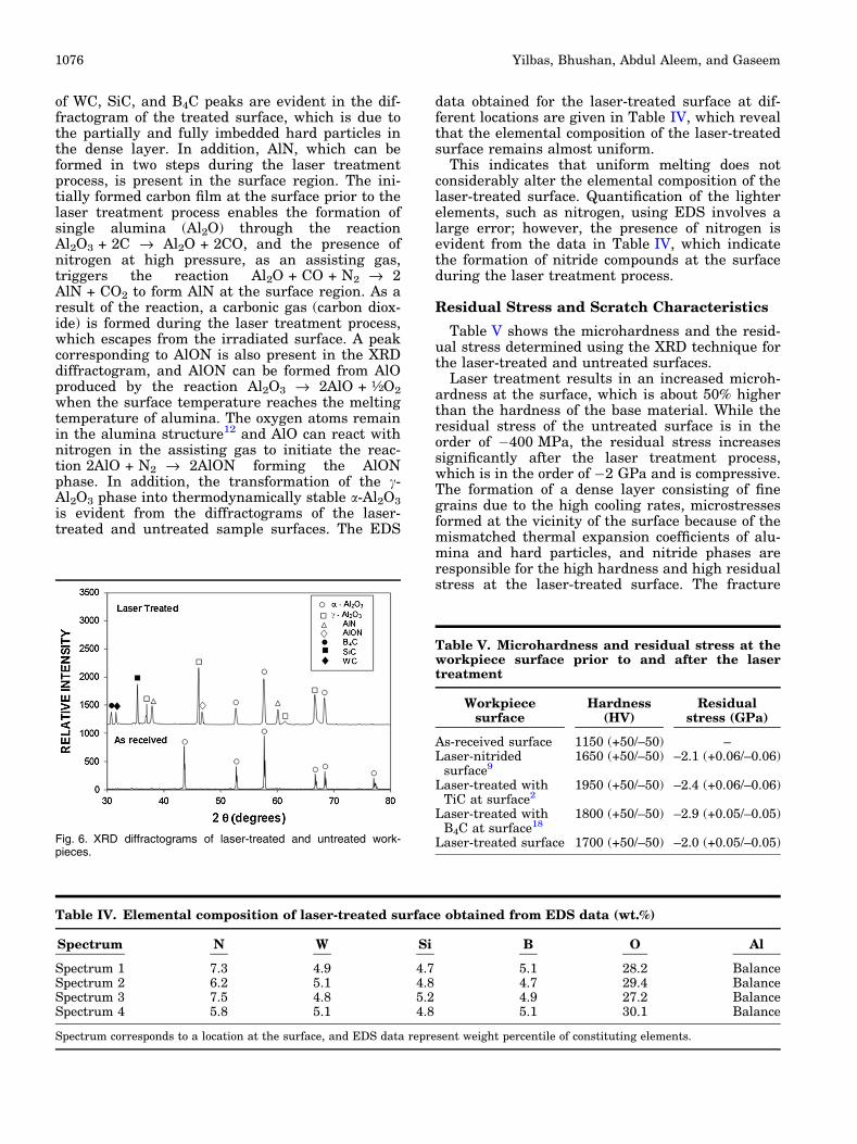
of WC, SiC, and B4C peaks are evident in the dif-fractogram of the treated surface, which is due tothe partially and fully imbedded hard particles inthe dense layer. In addition, AlN, which can beformed in two steps during the laser treatmentprocess, is present in the surface region. The ini-tially formed carbon film at the surface prior to thelaser treatment process enables the formation ofsingle alumina (Al2O) through the reactionAl2O3 + 2C fi Al2O + 2CO, and the presence ofnitrogen at high pressure, as an assisting gas,triggers the reaction Al2O + CO + N2 fi 2AlN + CO2 to form AlN at the surface region. As aresult of the reaction, a carbonic gas (carbon diox-ide) is formed during the laser treatment process,which escapes from the irradiated surface. A peakcorresponding to AlON is also present in the XRDdiffractogram, and AlON can be formed from AlOproduced by the reaction Al2O3 fi 2AlO + ½O2
when the surface temperature reaches the meltingtemperature of alumina. The oxygen atoms remainin the alumina structure12 and AlO can react withnitrogen in the assisting gas to initiate the reac-tion 2AlO + N2 fi 2AlON forming the AlONphase. In addition, the transformation of the c-Al2O3 phase into thermodynamically stable a-Al2O3
is evident from the diffractograms of the laser-treated and untreated sample surfaces. The EDS
data obtained for the laser-treated surface at dif-ferent locations are given in Table IV, which revealthat the elemental composition of the laser-treatedsurface remains almost uniform.
This indicates that uniform melting does notconsiderably alter the elemental composition of thelaser-treated surface. Quantification of the lighterelements, such as nitrogen, using EDS involves alarge error; however, the presence of nitrogen isevident from the data in Table IV, which indicatethe formation of nitride compounds at the surfaceduring the laser treatment process.
Residual Stress and Scratch Characteristics
Table V shows the microhardness and the resid-ual stress determined using the XRD technique forthe laser-treated and untreated surfaces.
Laser treatment results in an increased microh-ardness at the surface, which is about 50% higherthan the hardness of the base material. While theresidual stress of the untreated surface is in theorder of �400 MPa, the residual stress increasessignificantly after the laser treatment process,which is in the order of �2 GPa and is compressive.The formation of a dense layer consisting of finegrains due to the high cooling rates, microstressesformed at the vicinity of the surface because of themismatched thermal expansion coefficients of alu-mina and hard particles, and nitride phases areresponsible for the high hardness and high residualstress at the laser-treated surface. The fracture
Table IV. Elemental composition of laser-treated surface obtained from EDS data (wt.%)
Spectrum N W Si B O Al
Spectrum 1 7.3 4.9 4.7 5.1 28.2 BalanceSpectrum 2 6.2 5.1 4.8 4.7 29.4 BalanceSpectrum 3 7.5 4.8 5.2 4.9 27.2 BalanceSpectrum 4 5.8 5.1 4.8 5.1 30.1 Balance
Spectrum corresponds to a location at the surface, and EDS data represent weight percentile of constituting elements.
Table V. Microhardness and residual stress at theworkpiece surface prior to and after the lasertreatment
Workpiecesurface
Hardness(HV)
Residualstress (GPa)
As-received surface 1150 (+50/–50) –Laser-nitrided
surface91650 (+50/–50) –2.1 (+0.06/–0.06)
Laser-treated withTiC at surface2
1950 (+50/–50) –2.4 (+0.06/–0.06)
Laser-treated withB4C at surface18
1800 (+50/–50) –2.9 (+0.05/–0.05)
Laser-treated surface 1700 (+50/–50) –2.0 (+0.05/–0.05)Fig. 6. XRD diffractograms of laser-treated and untreated work-pieces.
Yilbas, Bhushan, Abdul Aleem, and Gaseem1076

toughness of the laser-treated surfaces measuredusing the indentation method, shown in Table II, isless than that for the untreated surface. The per-centage difference of the fracture toughness be-tween the laser-treated surface and the untreatedsurface is about 17%. Although fracture failurenormally takes place at the surface under tension, itcan also occur due to surface compressive stresseswhen the crack tip exceeds the sum of theoreticalstrength.
Figure 7 shows the scratch test results used todetermine the friction coefficient of the laser-treatedand untreated surfaces, and Fig. 8 shows the scarmark resulting from the scratch tests. The surfacefriction coefficient decreases after the laser treat-ment process, which is attributed to the low surfaceroughness and high hardness of the laser-treatedsurface. In addition, the presence of hard particlesat the surface lowers the scar depth and improvesthe friction coefficient. The optical image of the
Fig. 7. Scratch test results of friction coefficient for laser-treated and treated surfaces.
Tribology and Superhydrophobicity of Laser-Controlled-Melted Alumina Surfaces with Hard Particles 1077

scratched surface reveals that the scar size remainsalmost uniform along the tested surface and thedepth of the scar marks is very shallow. This indi-cates that the laser-treated surface responds to thescratch tests almost uniformly, indicating that themicrocracks formed at the laser surface do notcontribute to the scar size enlargement.
CONCLUSION
Laser-controlled melting of an alumina tile sur-face with a carbon film of about 40 lm thicknesswas conducted, in which carbide particles based onWC, SiC, and B4C are uniformly distributed. Thesurface morphology was examined using opticalmicroscopy and AFM, and the surface hydropho-bicity was assessed by the contact angle mea-surement. Chemical and structural changes in thelaser-treated layer and nitride compounds formedat the surface were determined using SEM, AFM,EDS, and XRD. The microhardness and fracturetoughness of the laser-treated surface were mea-sured using the indentation tests, while theresidual stress developed at the surfacewas determined using the XRD method. Scratchtests were conducted to measure the frictioncoefficient and scratch resistance of the laser-treated surface.
The laser-treated surface is free from large-scaleasperities including large cracks and cavities. Con-trolled melting and localized evaporation at thesurface resulted in a texture consisting of fine mi-cropoles, nanopoles, and micro cavities, which givesrise to contact angle enhancement at the surface.Although the Cassie and Baxter state dominatesover the laser-treated surface, local Wenzel statesare also observed at the treated surface. The laser-treated surface is composed of a fine texture withthe presence of some locally scattered small rough
regions. The use of nitrogen as an assisting gascauses nitride compounds to form at the treatedsurface, which in turn lowers the surface energyand enhances the surface hydrophobicity.
Partially embedded hard particles are observed atthe surface because of the high melting temperatureof the hard particles. As the thermal expansioncoefficients of the hard particles and alumina aredifferent, microstresses are formed in the vicinity ofthe hard particles. These, in turn, form few micro-cracks at the surface, although a crack network isnot observed at the surface. The laser-treated layerextends almost 40 lm below the surface, while thethickness of the dense layer is about 2 lm in thesurface region. It should be noted that the laser-treated layer is composed of the dense layer, whichis located in the surface region, a columnar struc-ture, which is located below the dense layer, and aheat-affected zone. Fine grains and few scatteredhard particles are observed in the dense layer. A fewvoids are formed around some of the hard particlesbecause of the volume shrinkage and wetting stateof the hard particles during solidification of thesurface.
Microhardness enhancement is about 50% at thelaser-treated surface, which is associated with thehigh cooling rates, microstresses due to presence ofhard particles, and volume shrinkage in the denselayer. A self-annealing effect of the laser scanningtracks by subsequent laser scanning modifies thecooling rates; thus, large-scale cracks are not ob-served across the cross section of the dense layer.AlN and AlON compounds are formed at the surfacebecause of the high-pressure-assisting gas usedduring the laser treatment process. The residualstress increase at the surface region is compressiveand it is of the order of �2 GPa. The friction coef-ficient of the laser-treated surface is lower andscratch resistance is better than that of the un-treated surface.
Fig. 8. Optical images of scar sites at laser-treated and untreated surfaces.
Yilbas, Bhushan, Abdul Aleem, and Gaseem1078

ACKNOWLEDGEMENTS
The authors acknowledge the support of Dean-ship of Scientific Research at King Fahd Universityof Petroleum and Minerals, Dhahran, Saudi Arabiafor the funding for project number SF131-CES-12.
REFERENCES
1. B. Bhushan and B.K. Gupta, Handbook of Tribology,Materials, Coatings, and Surface Treatments (New York:McGraw-Hill, 1991).
2. B. Bhushan, Introduction to Tribology, 2nd ed. (New York:Wiley, 2013).
3. B. Bhusha, Nanotribology and Nanomechanics, Vols. I andII, 3rd ed. (Heidelberg, Germany: Springer, 2011).
4. B.S. Yilbas, S.S. Akhtar, and C. Karatas, Surf. Eng. 27, 470(2011).
5. B.S. Yilbas, Surf. Interface Anal. 46, 30 (2014).6. S.P. Harimkar and N.B. Dahotre, J. Appl. Phys. 100, 024901
(2006).7. R. Krishnan, S. Dash, R. Kesavamoorthy, C. Babu Rao, A.K.
Tyagi, and B. Raj, Surf. Coat. Technol. 200, 2791 (2006).8. K. Yu, G. Zhang, N. Zheng, G. Liu, and Y. Zhang, Trans.
China Electrotech. Soc. 24, 28 (2009).9. B.S. Yilbas, M. Khaled, N. Abu-Dheir, N. Aqeeli, and S.Z.
Furquan, Appl. Surf. Sci. 286, 161 (2013).10. B.S. Yilbas, S.S. Akhtar, and C. Karatas, Opt. Lasers Eng.
49, 341 (2011).11. Y. Adraider, Y.X. Pang, F. Nabhani, S.N. Hodgson, M.C.
Sharp, and A. Al-Waidh, Ceram. Int. 40, 6151 (2014).12. B.S. Yilbas, C. Karatas, A.F.M. Arif, and B.J. Abdul Aleem,
Surf. Eng. 25, 235 (2009).13. A. Carrado, H. Pelletier, F. Sima, C. Ristoscu, A. Fabre, L.
Barrallier, and I.N. Mihailescu, Eng. Mater. 384, 185 (2008).14. M. Decup, D. Malec, and V. Bley, J. Appl. Phys. 106, 094103
(2009).
15. D. Triantafyllidis, L. Li, and F.H. Stott, Appl. Surf. Sci. 186,140 (2002).
16. A. Ibrahim, H. Salem, and S. Sedky, Surf. Coat. Technol.203, 3579 (2009).
17. R. Wallstabe, J. Mater. Eng. Perform. 22, 223 (2013).18. C. Dupas-Bruzek, L.D. Laude, F. Langenhorst, and K.
Kolev, J. Appl. Phys. 93, 4489 (2003).19. D. Sciti, C. Melandri, and A. Bellosi, J. Mater. Sci. 35, 3799
(2000).20. A.N. Samant, S.R. Paital, and N.B. Dahotre, J. Mater.
Process Technol. 203, 498 (2008).21. B.S. Yilbas, N. Al-Aqeeli, and C. Karatas, J. Alloy Compd.
539, 12 (2012).22. N.M. Khalil, J. Schneider, and G.K.-H. ZumGahr, Int. Cer-
am. Rev. 51, 144 (2002).23. B.S. Yilbas, C. Karatas, A.F.M. Arif, and B.J. Abdul, Aleem.
Opt. Laser Technol. 43, 858 (2011).24. M.A. Moncayo, S. Santhanakrishnan, V.H. Vora, S.R.
Paital, and N.B. Dahotre, Ceram. Int. 39, 6207 (2013).25. R.H.U. Khan, A.L. Yerokhin, T. Pilkington, A. Leyland, and
A. Matthews, Surf. Coat. Technol. 200, 1580 (2005).26. E.L. Cantera and B.G. Mellor, Mater. Lett. 37, 201 (1998).27. G.R. Anstis, P. Chantikul, B.R. Lawin, and D.B. Marshall,
J. Am. Ceram. Soc. 64, 533 (1981).28. A.G. Evans and E.A. Charles, J. Am. Ceram. Soc. 59, 370
(1976).29. B. Bhushan, Bioinspired Hierarchical-Structured Surfaces
for Green Science and Technology (Heidelberg, Germany:Springer, 2012).
30. B. Bhushan and Y.C. Jung, Progr. Mater. Sci. 56, 1 (2011).31. R.N. Wenzel, Ind. Eng. Chem. 28, 988 (1936).32. A.B.D. Cassie and S. Baxter, Trans. Faraday Soc. 40, 546
(1944).33. S. He, M. Zheng, L. Yao, X. Yuan, M. Li, L. Ma, and W.
Shen, Appl. Surf. Sci. 256, 2557 (2010).34. H.-W. Zan, K.-H. Yen, P.-K. Liu, K.-H. Ku, C.-H. Chen, and
J. Hwang, Org. Electron. 8, 450 (2007).
Tribology and Superhydrophobicity of Laser-Controlled-Melted Alumina Surfaces with Hard Particles 1079