triclinic, monoclinic and orthorhombic forms · hermann-mauguin symbol, and class name. crystal...
TRANSCRIPT
LECTURE NOTES 1ST
SEMESTER
UNIT- 3
Forms, Open and Closed
Any group of crystal faces related by the same symmetry is called a form. There are
47 or 48 crystal forms depending on the classification used.
Closed forms are those groups of faces all related by symmetry that completely
enclose a volume of space. It is possible for a crystal to have faces entirely of one
closed form. Open forms are those groups of faces all related by symmetry that do
not completely enclose a volume of space. A crystal with open form faces requires
additional faces as well. There are 17 or 18 open forms and 30 closed forms.
Triclinic, Monoclinic and Orthorhombic Forms
Pedion A single face unrelated to any other by symmetry. Open
Pinacoid A pair of parallel faces related by mirror plane or twofold symmetry axis. Open
Dihedron A pair of intersecting faces related by mirror plane or twofold symmetry axis.
Some crystallographers distinguish between domes (pairs of intersecting faces
related by mirror plane) and sphenoids (pairs of intersecting faces related by
twofold symmetry axis). All are open forms
Pyramid A set of faces related by symmetry and meeting at a common point. Open form.

3-, 4- and 6-Fold Prisms
Prism A collection of faces all parallel to a symmetry axis. All are open.
3-, 4- and 6-Fold Pyramids

Pyramid
A group of faces intersecting at a symmetry axis. All are open. The base of the
pyramid would be a pedion.
3-, 4- and 6-Fold Dipyramids
Dipyramid Two pyramids joined base to base along a mirror plane. All are closed, as are
all following forms.

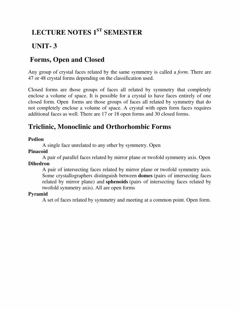
Scalenohedra and Trapezohedra
Disphenoid A solid with four congruent triangle faces, like a distorted tetrahedron.
Midpoints of edges are twofold symmetry axes. In the tetragonal disphenoid the
faces are isoceles triangles and a fourfold inversion axis joins the midpoints of
the bases of the isoceles triangles.
Scalenohedron A solid made up of scalene triangle faces (all sides unequal)
Trapezohedron A solid made of trapezia (irregular quadrilaterals)
Rhombohedron A solid with six congruent parallelogram faces. Can be considered a cube
distorted along one of its diagonal three-fold symmetry axes.
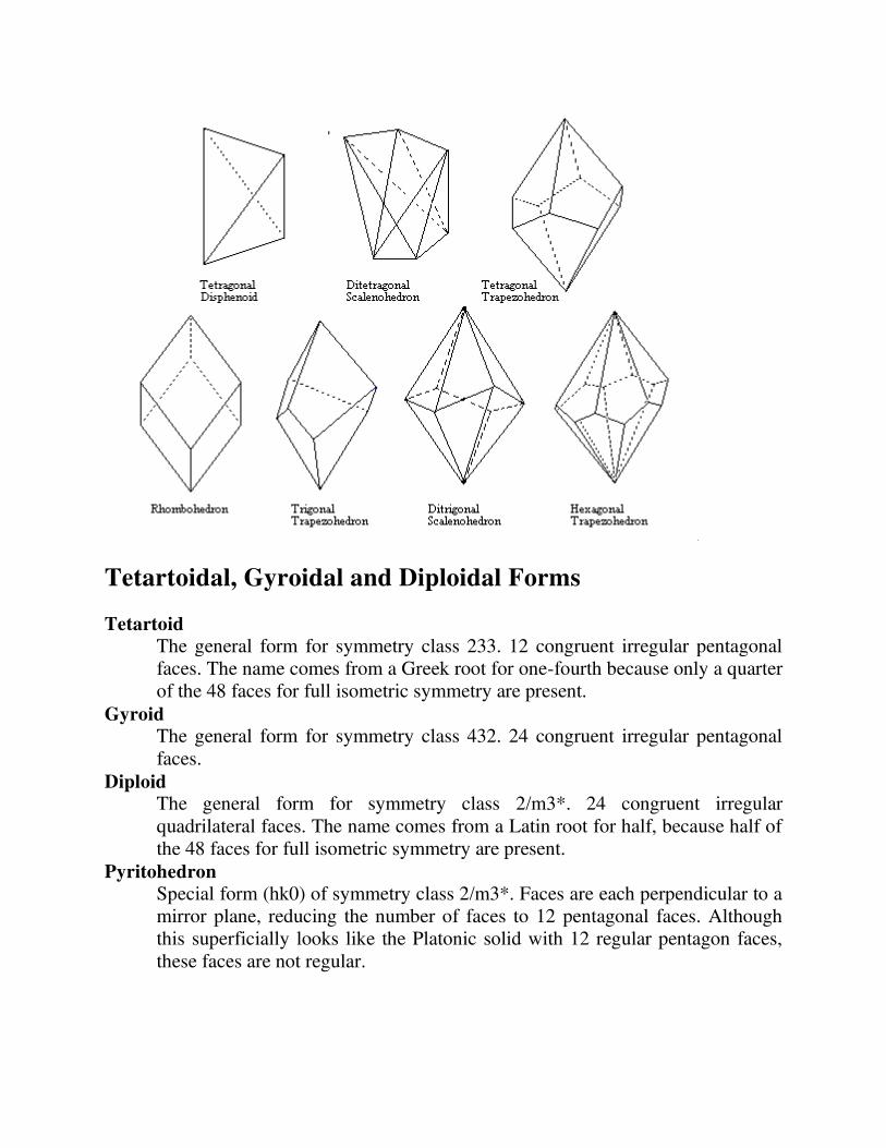
Tetartoidal, Gyroidal and Diploidal Forms
Tetartoid The general form for symmetry class 233. 12 congruent irregular pentagonal
faces. The name comes from a Greek root for one-fourth because only a quarter
of the 48 faces for full isometric symmetry are present.
Gyroid The general form for symmetry class 432. 24 congruent irregular pentagonal
faces.
Diploid The general form for symmetry class 2/m3*. 24 congruent irregular
quadrilateral faces. The name comes from a Latin root for half, because half of
the 48 faces for full isometric symmetry are present.
Pyritohedron Special form (hk0) of symmetry class 2/m3*. Faces are each perpendicular to a
mirror plane, reducing the number of faces to 12 pentagonal faces. Although
this superficially looks like the Platonic solid with 12 regular pentagon faces,
these faces are not regular.
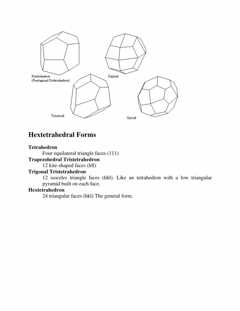
Hextetrahedral Forms
Tetrahedron Four equilateral triangle faces (111)
Trapezohedral Tristetrahedron 12 kite-shaped faces (hll)
Trigonal Tristetrahedron 12 isoceles triangle faces (hhl). Like an tetrahedron with a low triangular
pyramid built on each face.
Hextetrahedron 24 triangular faces (hkl) The general form.

Hexoctahedral Forms
Cube Six square faces (100).
Octahedron Eight equilateral triangle faces (111)
Rhombic Dodecahedron 12 rhombic faces (110)
Trapezohedral Trisoctahedron 24 kite-shaped faces (hhl). Note that the Miller indices for the two trisoctahedra
are the opposite of those for the tristetrahedra.
Trigonal Trisoctahedron 24 isoceles triangle faces (hll). Like an octahedron with a low triangular
pyramid built on each face.
Tetrahexahedron 24 isoceles triangle faces (h0l). Like an cube with a low pyramid built on each
face.
Hexoctahedron 48 triangular faces (hkl) The general form

COMPILED BY
GDC HANDWARA
LECTURE NOTES
1ST SEMESTER
UNIT 3
As stated in the last lecture, there are 32 possible combinations of
symmetry operations that define the external symmetry of crystals.
These 32 possible combinations result in the 32 crystal classes. These
are often also referred to as the 32 point groups. We will go over some
of these in detail in this lecture, but again I want to remind everyone
that the best way to see this material is by looking at the crystal models
in lab.
Hermann-Mauguin (International) Symbols
Before going into the 32 crystal classes, I first want to show you how to
derive the Hermann-Mauguin symbols (also called the international
symbols) used to describe the crystal classes from the symmetry
content. We'll start with a simple crystal then look at some more
complex examples.
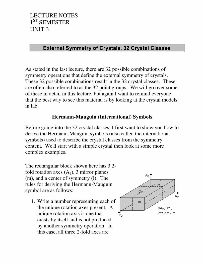
The rectangular block shown here has 3 2-
fold rotation axes (A2), 3 mirror planes
(m), and a center of symmetry (i). The
rules for deriving the Hermann-Mauguin
symbol are as follows:
1. Write a number representing each of
the unique rotation axes present. A
unique rotation axis is one that
exists by itself and is not produced
by another symmetry operation. In
this case, all three 2-fold axes are
External Symmetry of Crystals, 32 Crystal Classes

LECTURE NOTES
1ST SEMESTER
UNIT 3
unique, because each is
perpendicular to a different shaped
face, so we write a 2 (for 2-fold) for
each axis
2 2 2
2. Next we write an "m" for each unique mirror plane. Again, a
unique mirror plane is one that is not produced by any other
symmetry operation. In this example, we can tell that each mirror
is unique because each one cuts a different looking face. So, we
write:
2 m 2 m 2 m
3. If any of the axes are perpendicular to a mirror plane we put a
slash (/) between the symbol for the axis and the symbol for the
mirror plane. In this case, each of the 2-fold axes are
perpendicular to mirror planes, so our symbol becomes:
2/m2/m2/m
If you look in the table given in the lecture notes below, you will see
that this crystal model belongs to the Rhombic-dipyramidal class.
Our second example involves the block shown
here to the right. This model has one 2-fold
axis and 2 mirror planes. For the 2-fold axis,
we write:
2
Each of the mirror planes is unique. We can
tell that because each one cuts a different
LECTURE NOTES
1ST SEMESTER
UNIT 3
looking face. So, we write 2 "m"s, one for
each mirror plane:
2 m m
Note that the 2-fold axis is not perpendicular to a mirror plane, so we
need no slashes. Our final symbol is then:
2mm
For this crystal class, the convention is to write mm2 rather than 2mm
(I'm not sure why). If you consult the table below, you will see that
this crystal model belongs to the Rhombic-pyramidal class.
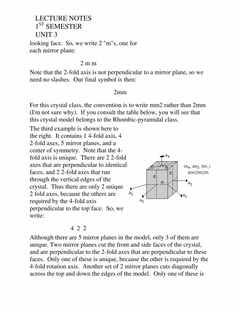
The third example is shown here to
the right. It contains 1 4-fold axis, 4
2-fold axes, 5 mirror planes, and a
center of symmetry. Note that the 4-
fold axis is unique. There are 2 2-fold
axes that are perpendicular to identical
faces, and 2 2-fold axes that run
through the vertical edges of the
crystal. Thus there are only 2 unique
2 fold axes, because the others are
required by the 4-fold axis
perpendicular to the top face. So, we
write:
4 2 2
Although there are 5 mirror planes in the model, only 3 of them are
unique. Two mirror planes cut the front and side faces of the crystal,
and are perpendicular to the 2-fold axes that are perpendicular to these
faces. Only one of these is unique, because the other is required by the
4-fold rotation axis. Another set of 2 mirror planes cuts diagonally
across the top and down the edges of the model. Only one of these is

LECTURE NOTES
1ST SEMESTER
UNIT 3
unique, because the other is generated by the 4-fold rotation axis and
the previously discussed mirror planes. The mirror plane that cuts
horizontally through the crystal and is perpendicular to the 4-fold axis
is unique. Since all mirror unique mirror planes are perpendicular to
rotation axes, our final symbol becomes:
4/m2/m2/m
Looking in the table below, we see that this crystal belongs to the
Ditetragonal-dipyramidal class.
Our last example is the
most complex. Note
that it has 3 4-fold
rotation axes, each of
which is perpendicular
to a square shaped face,
4 3-fold rotoinversion
axes (some of which are
not shown in the
diagram to reduce
complexity), each
sticking out of the
corners of the cube, and
6 2-fold rotation axes
(again, not all are
shown), sticking out of
the edges of the cube.
In addition, the crystal
has 9 mirror planes, and
a center of symmetry.
LECTURE NOTES
1ST SEMESTER
UNIT 3
There is only 1 unique 4 fold axis, because each is perpendicular to a
similar looking face (the faces of the cube). There is only one unique
3-fold rotoinversion axes, because all of them stick out of the corners
of the cube, and all are related by the 4-fold symmetry. And, there is
only 1 unique 2-fold axis, because all of the others stick out of the
edges of the cube and are related by the mirror planes the other set of 2-
fold axes. So, we write a 4, a , and a 2 for each of the unique rotation
axes.
4 2
There are 3 mirror planes that are perpendicular to the 4 fold axes, and
6 mirror planes that are perpendicular to the 2-fold axes. No mirror
planes are perpendicular to the 3-fold rotoinversion axes. So, our final
symbol becomes:
4/m 2/m
Consulting the table in the lecture notes below, reveals that this crystal
belongs to the hexoctahedral crystal class.
The 32 Crystal Classes
The 32 crystal classes represent the 32 possible combinations of
symmetry operations. Each crystal class will have crystal faces that
uniquely define the symmetry of the class. These faces, or groups of
faces are called crystal forms. Note that you are not expected to
memorize the crystal classes, their names, or the symmetry associated
with each class. You will, however, be expected to determine the
symmetry content of crystal models, after which you can consult the
tables in your textbook, lab handouts, or lecture notes. All testing on
this material in the lab will be open book.
In this lecture we will go over some of the crystal classes and their
symmetry. I will not be able to cover all of the 32 classes. You will,

LECTURE NOTES
1ST SEMESTER
UNIT 3
however, see many of the 32 classes during your lab work. Note that it
is not easy to draw a crystal of some classes without adding more
symmetry or that can be easily seen in a two dimensional drawing.
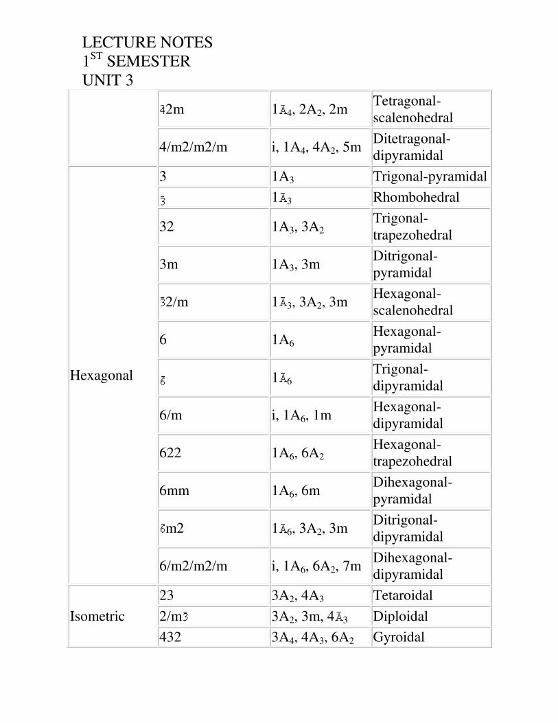
The table below shows the 32 crystal classes, their symmetry,
Hermann-Mauguin symbol, and class name.
Crystal
System Crystal Class Symmetry Name of Class
Triclinic 1 none Pedial
i Pinacoidal
Monoclinic
2 1A2 Sphenoidal
m 1m Domatic
2/m i, 1A2, 1m Prismatic
Orthorhombic
222 3A2 Rhombic-
disphenoidal
mm2 (2mm) 1A2, 2m Rhombic-
pyramidal
2/m2/m2/m i, 3A2, 3m Rhombic-
dipyramidal
Tetragonal
4 1A4 Tetragonal-
Pyramidal
4 Tetragonal-
disphenoidal
4/m i, 1A4, 1m Tetragonal-
dipyramidal
422 1A4, 4A2 Tetragonal-
trapezohedral
4mm 1A4, 4m Ditetragonal-
pyramidal
LECTURE NOTES
1ST SEMESTER
UNIT 3
2m 1 4, 2A2, 2m Tetragonal-
scalenohedral
4/m2/m2/m i, 1A4, 4A2, 5m Ditetragonal-
dipyramidal
Hexagonal
3 1A3 Trigonal-pyramidal
1 3 Rhombohedral
32 1A3, 3A2 Trigonal-
trapezohedral
3m 1A3, 3m Ditrigonal-
pyramidal
2/m 1 3, 3A2, 3m Hexagonal-
scalenohedral
6 1A6 Hexagonal-
pyramidal
1 6 Trigonal-
dipyramidal
6/m i, 1A6, 1m Hexagonal-
dipyramidal
622 1A6, 6A2 Hexagonal-
trapezohedral
6mm 1A6, 6m Dihexagonal-
pyramidal
m2 1 6, 3A2, 3m Ditrigonal-
dipyramidal
6/m2/m2/m i, 1A6, 6A2, 7m Dihexagonal-
dipyramidal
Isometric
23 3A2, 4A3 Tetaroidal
2/m 3A2, 3m, 4 3 Diploidal
432 3A4, 4A3, 6A2 Gyroidal

LECTURE NOTES
1ST SEMESTER
UNIT 3
3m 3 4, 4A3, 6m Hextetrahedral
4/m 2/m 3A4, 4 3, 6A2,
9m Hexoctahedral
Note that the 32 crystal classes are divided into 6 crystal systems.
1. The Triclinic System has only 1-fold or 1-fold rotoinversion axes.
2. The Monoclinic System has only mirror plane(s) or a single 2-fold
axis.
3. The Orthorhombic System has only two fold axes or a 2-fold axis
and 2 mirror planes.
4. The Tetragonal System has either a single 4-fold or 4-fold
rotoinversion axis.
5. The Hexagonal System has no 4-fold axes, but has at least 1 6-fold
or 3-fold axis.
6. The Isometric System has either 4 3-fold axes or 4 3-fold
rotoinversion axes.
Triclinic System
Characterized by only 1-fold or 1-fold rotoinversion axis
Pedial Class, 1, Symmetry content - none

LECTURE NOTES
1ST SEMESTER
UNIT 3
In this class there is no symmetry, so all crystal faces are unique
and are not related to each other by symmetry. Such faces are
called Pedions, thus this is the Pedial Class. Only a few rare
minerals are in this class.
Pinacoidal Class, , Symmetry content - i
Since in this class there is only a center of
symmetry, pairs of faces are related to each other
through the center. Such faces are called
pinacoids, thus this is the pinacoidal class.
Among the common minerals with pinacoidal
crystals are: microcline (K-feldspar), plagioclase,
turquoise, and wollastonite.
Monoclinic System
Characterized by having only mirror plane(s) or a single 2-fold axis.
Sphenoidal Class, 2, Symmetry content - 1A2
In this class there is a single 2-fold rotation
axis. Faces related by a 2-fold axis are called
sphenoids, thus this is the sphenoidal class.
Only rare minerals belong to this class.

LECTURE NOTES
1ST SEMESTER
UNIT 3
Domatic Class, m, Symmetry content -
1m
This class has a single mirror plane.
Faces related by a mirror plane are called
domes, thus this is the domatic class.
Only 2 rare minerals crystallize in this
class.
Prismatic Class, 2/m. Symmetry content - 1A2,
m, i
This class has a single 2-fold axis perpendicular
to a single mirror plane. This class has pinacoid
faces and prism faces. A prism is defined as 3 or
more identical faces that are all parallel to the
same line. In the prismatic class, these prisms
consist of 4 identical faces, 2 of which are shown
in the diagram on the front of the crystal. The
other two are on the back side of the crystal.
The most common minerals that occur in the prismatic class are
the micas (biotite and muscovite), azurite, chlorite,
clinopyroxenes, epidote, gypsum, malachite, kaolinite, orthoclase,
and talc.
Orthorhombic System
Characterized by having only two fold axes or a 2-fold axis and 2
LECTURE NOTES
1ST SEMESTER
UNIT 3
mirror planes.
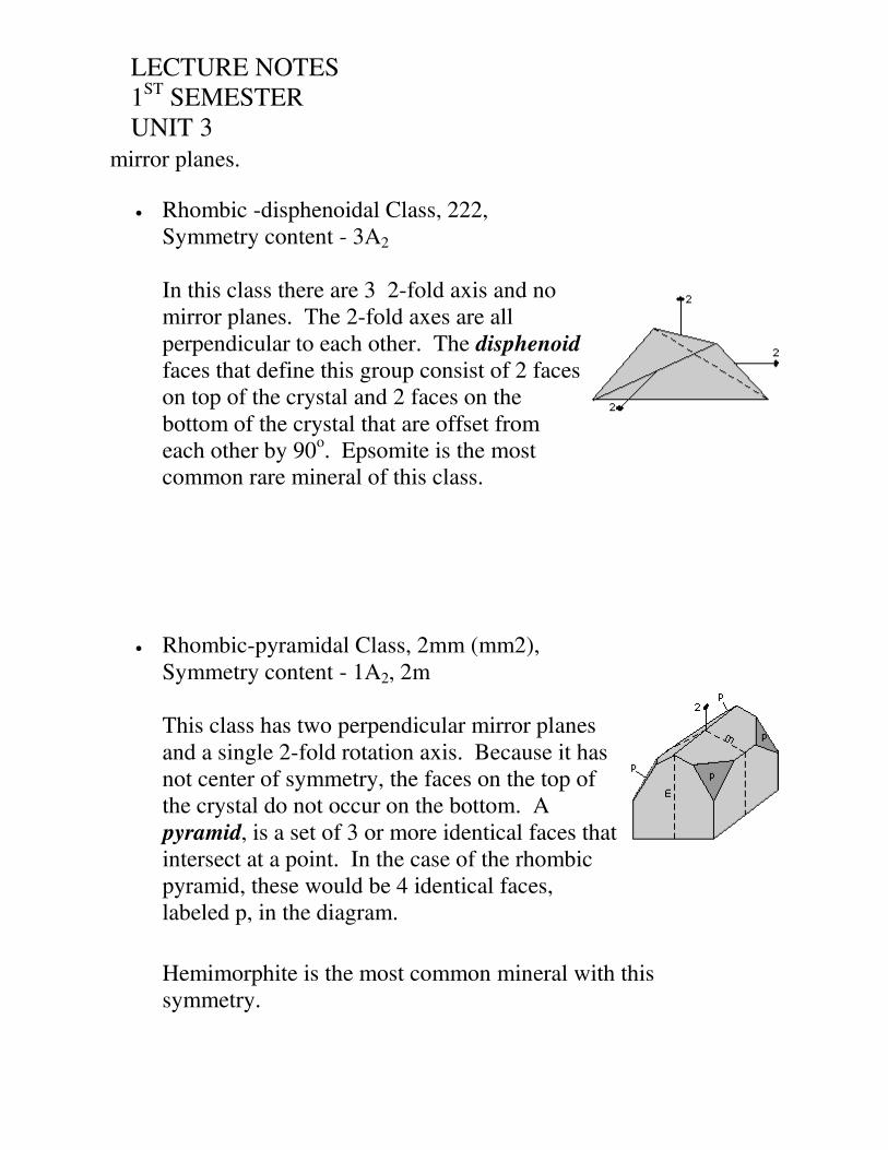
Rhombic -disphenoidal Class, 222,
Symmetry content - 3A2
In this class there are 3 2-fold axis and no
mirror planes. The 2-fold axes are all
perpendicular to each other. The disphenoid
faces that define this group consist of 2 faces
on top of the crystal and 2 faces on the
bottom of the crystal that are offset from
each other by 90o. Epsomite is the most
common rare mineral of this class.
Rhombic-pyramidal Class, 2mm (mm2),
Symmetry content - 1A2, 2m
This class has two perpendicular mirror planes
and a single 2-fold rotation axis. Because it has
not center of symmetry, the faces on the top of
the crystal do not occur on the bottom. A
pyramid, is a set of 3 or more identical faces that
intersect at a point. In the case of the rhombic
pyramid, these would be 4 identical faces,
labeled p, in the diagram.
Hemimorphite is the most common mineral with this
symmetry.

LECTURE NOTES
1ST SEMESTER
UNIT 3
Rhombic-dipyramidal Class, 2/m2/m2/m,
Symmetry content - 3A2, 3m, i
This class has 3 perpendicular 2-fold axes that are
perpendicular to 3 mirror planes. The dipyramid
faces consist of 4 identical faces on top and 4
identical faces on the bottom that are related to
each other by reflection across the horizontal
mirror plane or by rotation about the horizontal 2-
fold axes.
The most common minerals in this class are
andalusite, anthophyllite, aragonite, barite,
cordierite, olivine, sillimanite, stibnite, sulfur, and
topaz.
Tetragonal System
Characterized by a single 4-fold or 4-fold rotoinversion axis.
Tetragonal-pyramidal Class, 4, Symmetry
content - 1A4
Since this class has a single 4-fold axis
and no mirror planes, there are no
pyramid faces on the bottom of the
crystal. Wulfinite is the only mineral
known to crystallize in this class.

LECTURE NOTES
1ST SEMESTER
UNIT 3
Tetragonal-disphenoidal Class, , Symmetry content -
1 4
With only a single 4-fold rotoinversion axis, the
disphenoid faces consist of two identical faces on top,
and two identical faces on the bottom, offset by 90o.
Note that there are no mirror planes in this class. Only
one rare mineral is known to form crystals of this class.
Tetragonal-dipyramidal Class, 4/m, Symmetry content -
1A4, 1m, i
This class has a single 4-fold axis perpendicular to a
mirror plane. This results in 4 pyramid faces on top
that are reflected across the mirror plane to form 4
identical faces on the bottom of the crystal. Scheelite
and scapolite are the only common minerals in this
class.
Tetragonal-trapezohedral Class, 422, Symmetry
content - 1A4, 4A2
This class has a 4 fold axis perpendicular to 4 2-
fold axes. There are no mirror planes. Only one
rare mineral belongs to this class.

LECTURE NOTES
1ST SEMESTER
UNIT 3
Ditetragonal-pyramidal Class, 4mm, Symmetry content -
1A4, 4m
This class has a single 4-fold axis and 4 mirror planes.
The mirror planes are not shown in the diagram, but
would cut through the edges and center of the faces
shown. Note that the ditetragonal pyramid is a set of 8
faces that form a pyramid on the top of the crystal. Only
one rare mineral forms in the crystal class.
Tetragonal-scalenohedral Class, 2m, Symmetry
Content - 1 4, 2A2, 2m
This class has a 4-fold rotoinversion axis that is
perpendicular to 2 2-fold rotation axes. The 2
mirror planes a parallel to the and are at 45o to the
2-fold axes. Chalcopyrite and stannite are the only
common minerals with crystals in this class.
Ditetragonal-dipyramidal Class, 4/m2/m2/m,
Symmetry content - 1A4, 4A2, 5m, i
This class has the most symmetry of the
tetragonal system. It has a single 4-fold axis
that is perpendicular to 4 2-fold axes. All of
the 2-fold axes are perpendicular to mirror
planes. Another mirror plane is perpendicular
to the 4-fold axis. The mirror planes are not
shown in the diagram, but would cut through
all of the vertical edges and through the center

LECTURE NOTES
1ST SEMESTER
UNIT 3
of the pyramid faces. The fifth mirror plane is
the horizontal plane. Note the ditetragonal-
dipyramid consists of the 8 pyramid faces on
the top and the 8 pyramid faces on the
bottom.
Common minerals that occur with this symmetry are
anatase, cassiterite, apophyllite, zircon, and vesuvianite.
Note that I will not have time in lecture to cover the rest of the 32
crystal classes, that is those belonging to the hexagonal and isometric
systems. These are difficult to draw, and are best left for the student to
study using the textbook, pages 180-205, and the crystal models in lab.
Examples of questions on this material that could be asked on an
exam
1. Why are there only 32 classes of crystals?
2. What criteria is involved in dividing the 32 crystal classes into 6
crystal systems?
3. Note that exams where you will be asked to recognize the
different crystal classes and their symmetry, the exams will be
open book, so you will have access to the tables and figures in
these notes.

LECTURE NOTES 1ST SEMESTER UNIT-3
Axial Ratios, Parameters, Miller Indices Crystallographic axes can be defined for the various crystal systems. Two important points to remember are that
1. The lengths of the crystallographic axes are controlled by the dimensions of the unit cell upon which the crystal is based.
2. The angles between the crystallographic axes are controlled by the shape of the unit cell.
We also noted last time that the relative lengths of the crystallographic axes control the angular relationships between crystal faces. This is true because crystal faces can only develop along lattice points. The relative lengths of the crystallographic axes are called axial ratios, our first topic of discussion.
Axial Ratios
Axial ratios are defined as the relative lengths of the crystallographic axes. They are normally taken as relative to the length of the b crystallographic axis. Thus, an axial ratio is defined as follows:
Axial Ratio = a/b : b/b : c/b
where a is the actual length of the a crystallographic axis, b, is the actual length of the b crystallographic axis, and c is the actual length of the c crystallographic axis.
For Triclinic, Monoclinic, and Orthorhombic crystals, where the lengths of the three axes are different, this reduces to
a/b : 1 : c/b (this is usually shortened to a : 1 : c)
For Tetragonal crystals where the length of the a and b axes are equal, this reduces to
1 : 1 : c/b (this is usually shorted to 1 : c)
For Isometric crystals where the length of the a, b, and c axes are equal this becomes

1 : 1 : 1 (this is usually shorted to 1)
For Hexagonal crystals where there are three equal length axes (a1, a2, and a3) perpendicular to the c axis this becomes:
1 : 1 : 1: c/a (usually shortened to 1 : c)
Modern crystallographers can use x-rays to determine the size of the unit cell, and thus can determine the absolute value of the crystallographic axes. For example, the mineral quartz is hexagonal, with the following unit cell dimensions as determined by x-ray crystallography:
a1 = a2 = a3 = 4.913Å
c = 5.405Å
where Å stands for Angstroms = 10-10 meter.
Thus the axial ratio for quartz is
1 : 1 : 1 : 5.405/4.913
or
1: 1 : 1 : 1.1001
which simply says that the c axis is 1.1001 times longer than the a axes.
For orthorhombic sulfur the unit cell dimensions as measured by x-rays are:
a = 10.47Å
b = 12.87Å
c = 24.39Å
Thus, the axial ratio for orthorhombic sulfur is:
10.47/12.87 : 12.87/12.87 : 24.39/12.87
or
0.813 : 1 : 1.903
Because crystal faces develop along lattice points, the angular relationship between faces must depend on the relative lengths of the axes. Long before x-rays were invented and

absolute unit cell dimensions could be obtained, crystallographers were able to determine the axial ratios of minerals by determining the angles between crystal faces. So, for example, in 1896 the axial ratios of orthorhombic sulfur were determined to be nearly exactly the same as those reported above from x-ray measurements.
In a later lecture we will see how we can determine axial ratios from the angular relationships between faces. First, however we must determine how we can name, or index faces of crystals and define directions within crystals.
Intercepts of Crystal Faces (Weiss Parameters)
Crystal faces can be defined by their intercepts on the crystallographic axes. For non-hexagonal crystals, there are three cases.
1. A crystal face intersects only one of the crystallographic axes. As an example the top crystal face shown here intersects the c axis but does not intersect the a or b axes. If we assume that the face intercepts the c axis at a distance of 1 unit length, then the intercepts, sometimes called Weiss Parameters, are: a, b, 1c
2. A crystal face intersects two of the crystallographic axes. As an example, the darker crystal face shown here intersects the a and b axes, but not the c axis. Assuming the face intercepts the a and c axes at 1 unit cell length on each, the parameters for this face are: 1 a, 1 b, c

3. A crystal face that intersects all 3 axes. In this example the darker face is assumed to intersect the a, b, and c crystallographic axes at one unit length on each. Thus, the parameters in this example would be: 1a, 1b, 1c
Two very important points about intercepts of faces:
The intercepts or parameters are relative values, and do not indicate any actual cutting lengths.
Since they are relative, a face can be moved parallel to itself without changing its relative intercepts or parameters.
Because one does usually not know the dimensions of the unit cell, it is difficult to know what number to give the intercept of a face, unless one face is chosen arbitrarily to have intercepts of 1. Thus, the convention is to assign the largest face that intersects all 3 crystallographic axes the parameters - 1a, 1b, 1c. This face is called the unit face.
For example, in the orthorhombic crystal shown here, the large dark shaded face is the largest face that cuts all three axes. It is the unit face, and is therefore assigned the parameters 1a, 1b, 1c.

Once the unit face is defined, the intercepts of the smaller face can be determined. These are 2a, 2b, 2/3c. Note that we can divide these parameters by the common factor 2, resulting in 1a,1b,1/3c. Again, this illustrates the point that moving a face parallel to itself does not change the relative intercepts. Since intercepts or parameters are relative, they do not represent the actual cutting lengths on the axes.
By specifying the intercepts or parameters of a crystal face, we now have a way to uniquely identify each face of a crystal. But, the notation is cumbersome, so crystallographers have developed another way of identifying or indexing faces. This conventional notation called the Miller Index is our next topic of discussion.
Miller Indices
The Miller Index for a crystal face is found by
first determining the parameters second inverting the parameters, and third clearing the fractions.
For example, if the face has the parameters 1 a, 1 b, c
inverting the parameters would be 1/1, 1/1, 1/
this would become 1, 1, 0
the Miller Index is written inside parentheses with no commas - thus (110)

As further examples, let's look at the crystal shown here. All of the faces on this crystal are relatively simple. The face [labeled (111)] that cuts all three axes at 1 unit length has the parameters 1a, 1b, 1c. Inverting these, results in 1/1, 1/1, 1/1 to give the Miller Index (111).
The square face that cuts the positive a axis, has the parameters 1 a, b, c. Inverting these becomes 1/1, 1/to give the Miller Index (100).
The face on the back of the crystal that cuts the negative a axis has the parameters -1a, b, c. So its Miller Index is ( 00). Note how the negative intercept is indicated by putting a minus sign above the index. This would be read "minus one, one, one". Thus, the other 4 faces seen on this crystal would have the Miller Indices (001), (00 ), (010), and (0 0).
Now let's look at some more complicated examples. The drawing to the right is the same orthorhombic crystal we looked at earlier. Recall that the small triangular face near the top that cuts all three axes had the parameters 1a, 1b, 1/3c. Inverting these becomes 1/1, 1/1, 3/1 to give the Miller Index for this face as (113).
Similarly, the small triangular face the cuts the positive a axis and the negative b axis, would have the Miller Index (1 3), the similar face on the bottom of the crystal, cutting positive a, positive b, and negative c axes would have the Miller Index (11 ).
See if you can determine the Miller Indices for the 8 faces on the back of the crystal that are not seen in this drawing.
Note once again, that moving a face parallel to itself does not change the parameters nor the Miller Index for that face.
To refer to a general face that intersects all three crystallographic axes where the parameters are not known, we use the notation (hkl). For a face that intersects the b and c axes with general or unknown intercepts the notation would be (0kl), for a face intersecting the a and c axis, but parallel to b the notation would be (h0l), and similarly for a face intersecting the a and b axes, but parallel to c we would use the notation (hk0).
This Miller Index notation applies very well to crystals in the Triclinic, Monoclinic,

Orthorhombic, Tetragonal, and Isometric systems, but requires some modification to be applied to the Hexagonal crystal system.
Miller Bravais Indices
Since the hexagonal system has three "a" axes perpendicular to the "c" axis, both the parameters of a face and the Miller Index notation must be modified. The modified parameters and Miller Indices must reflect the presence of an additional axis. This modified notation is referred to as Miller-Bravais Indices, with the general notation (hkil)
To see how this works, let's look at the dark shaded face in the hexagonal crystal shown here. This face intersects the positive a1 axis at 1 unit length, the negative a3 axis at 1 unit length, and does not intersect the a2 or c axes. This face thus has the parameters:
1 a1, a2, -1 a3, c
Inverting and clearing fractions gives the Miller-Bravais Index:
(10 0)
An important rule to remember in applying this notation in the hexagonal system, is that whatever indices are determined for h, k, and i,
h + k + i = 0

For a similar hexagonal crystal, this time with the shaded face cutting all three axes, we would find for the shaded face in the diagram that the parameters are 1 a1, 1 a2, -1/2 a3, c. Inverting these intercepts gives:
1/1, 1/1, -2/1, 1/
resulting in a Miller-Bravais Index of
(11 0)
Note how the "h + k + i = 0" rule applies here!
Crystal Forms
Although we will not cover this in detail in this lecture, the next step is to use the Miller Index notation to designate crystal forms. A crystal form is a set of crystal faces that are related to each other by symmetry. To designate a crystal form (which could imply many faces) we use the Miller Index, or Miller-Bravais Index notation enclosing the indices in curly braces, i.e.
{hkl} or {hkil}
Such notation is called a form symbol.
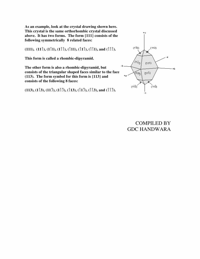
As an example, look at the crystal drawing shown here. This crystal is the same orthorhombic crystal discussed above. It has two forms. The form {111} consists of the following symmetrically 8 related faces:
(111), (11 ), (1 1), (1 ), ( 11), ( 1 ), ( 1), and ( ).
This form is called a rhombic-dipyramid.
The other form is also a rhombic-dipyramid, but consists of the triangular shaped faces similar to the face (113). The form symbol for this form is {113} and consists of the following 8 faces:
(113), (1 3), (11 ), (1 ), ( 13), ( 1 ), ( 3), and ( ).
COMPILED BY
GDC HANDWARA

LECTURE NOTES
1ST
SEMESTER
UNIT 3
Twinning, Polymorphism, Polytypism, &Pseudomorphism
Twinning in Crystals
Sometimes during the growth of a crystal, or if the crystal is subjected
to stress or temperature/pressure conditions different from those under
which it originally formed, two or more intergrown crystals are formed
in a symmetrical fashion. These symmetrical intergrowths of crystals
are called twinned crystals. Twinning is important to recognize,
because when it occurs, it is often one of the most diagnostic features
enabling identification of the mineral.
What happens is that lattice points in one
crystal are shared as lattice points in another
crystal adding apparent symmetry to the
crystal pairs. Twinning, because it adds
symmetry, never occurs in relation to the
existing symmetry of the crystal.
Symmetry Operations that Define Twinning
Because symmetry is added to a crystal by twinning, twining can be
defined by the symmetry operations that are involved. These include:
Reflection across a mirror plane. The added mirror plane would
then be called a twin plane.
Rotation about an axis or line in the crystal. The added rotation
axis would then be called a twin axis.
Inversion through a point. The added center of symmetry would
then be called a twin center.
Twin Laws
Twin laws are expressed as either form symbols to define twin planes
(i.e. {hkl}) or zone symbols to define the direction of twin axes (i.e.
[hkl]).
The surface along which the lattice points are shared in twinned
crystals is called a composition surface.
If the twin law can be defined by a simple planar composition surface,
the twin plane is always parallel to a possible crystal face and never
parallel to an existing plane of symmetry (remember that twinning adds
symmetry).
If the twin law is a rotation axis, the composition surface will be
irregular, the twin axis will be perpendicular to a lattice plane, but will
never be an even-fold rotation axis of the existing symmetry. For
example twinning cannot occur on a new 2 fold axis that is parallel to
an existing 4-fold axis.
Types of Twinning
Another way of defining twinning breaks twins into two separate types.

1. Contact Twins - have a planar composition surface
separating 2 individual crystals. These are usually
defined by a twin law that expresses a twin plane
(i.e. an added mirror plane). An example shown
here is a crystal of orthoclase twinned on the
Braveno Law, with {021} as the twin plane.
2. Penetration Twins - have an irregular composition
surface separating 2 individual crystals. These are
defined by a twin center or twin axis. Shown here is a
twinned crystal of orthoclase twinned on the Carlsbad
Law with [001] as the twin axis.
Contact twins can also occur as repeated or multiple
twins.
If the compositions surfaces are parallel to one
another, they are called polysynthetic twins.
Plagioclase commonly shows this type of
twinning, called the Albite Twin Law, with
{010} as the twin plane. Such twinning is one
of the most diagnostic features of plagioclase.
If the composition surfaces are not parallel to one
another, they are called cyclical twins. Shown here is
the cyclical twin that occurs in chrysoberyl along a
{031} plane.
Origin of Twinning
Twinning can originate in 3 different ways, as growth twins,
transformation twins, and glide or deformation twins.
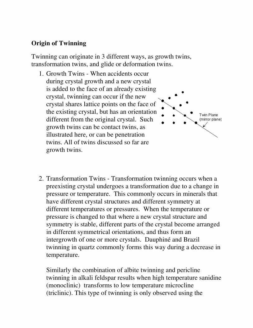
1. Growth Twins - When accidents occur
during crystal growth and a new crystal
is added to the face of an already existing
crystal, twinning can occur if the new
crystal shares lattice points on the face of
the existing crystal, but has an orientation
different from the original crystal. Such
growth twins can be contact twins, as
illustrated here, or can be penetration
twins. All of twins discussed so far are
growth twins.
2. Transformation Twins - Transformation twinning occurs when a
preexisting crystal undergoes a transformation due to a change in
pressure or temperature. This commonly occurs in minerals that
have different crystal structures and different symmetry at
different temperatures or pressures. When the temperature or
pressure is changed to that where a new crystal structure and
symmetry is stable, different parts of the crystal become arranged
in different symmetrical orientations, and thus form an
intergrowth of one or more crystals. Dauphiné and Brazil
twinning in quartz commonly forms this way during a decrease in
temperature.
Similarly the combination of albite twinning and pericline
twinning in alkali feldspar results when high temperature sanidine
(monoclinic) transforms to low temperature microcline
(triclinic). This type of twinning is only observed using the

polarizing microscope, and results in a "tartan" twinning pattern
as shown in your text book on page 231, figure10.18. When this
twinning pattern is observed with the microscope it is one of the
most characteristic diagnostic properties for the identification of
microcline.
3. Deformation
Twins - During
deformation
atoms can be
pushed out of
place. If this
happens to
produce a
symmetrical
arrangement, it
produces
deformation
twins. The
mineral calcite
can be easily
twinned in this
way, producing
polysynthetic
twins on {01 2}.
Common Twin Laws
Triclinic System - The feldspar minerals plagioclase and

microcline are the most common triclinic minerals that show
twinning. Two common twin laws are observed in these
feldspars.
o Albite Law - As described above,
plagioclase (NaAlSi3O8 - CaAl2Si2O8)
very commonly shows albite
polysynthetic twinning. The twin law -
{010} indicates that the twining occurs
perpendicular to the b crystallographic
axis. Albite twinning is so common in
plagioclase, that it's presence is a
diagnostic property for identification of
plagioclase.
o Pericline Law - The pericline law has [010] as the twin
axis. As stated above, pericline twinning occurs as the
result of monoclinic orthoclase or sanidine transforming to
microcline (all have the same chemical formula -
KAlSi3O8). Pericline twinning usually occurs in
combination with albite twinning in microcline, but is only
observable with the polarizing microscope. The
combination of pericline and albite twinning produce a
cross-hatched pattern, called tartan twinning, as discussed
above, that easily distinguishes microcline from the other
feldspars under the microscope.
Monoclinic System - The most common twins in the monoclinic
system occur on the planes {100} and {001}. The feldspars -
orthoclase and sanidine - are the most commonly twinned
minerals in the monoclinic system. Both contact twins and
penetration twins occur, and both types result from accidents
during growth.

o Manebach Law - {001} - forms a contact
twin commonly observed in the mineral
orthoclase. This twinning is very diagnostic
of orthoclase when it occurs.
o Carlsbad Law - [001] - forms a penetration twin
in the mineral orthoclase. Crystals twinned under
the Carlsbad Law show two intergrown crystals,
one rotated 180o from the other about the [001]
axis. Carlsbad twinning is the most common type
of twinning in orthoclase, and is thus very
diagnostic of orthoclase when it occurs.
o Braveno Law - {021} - forms a contact twin
in the mineral orthoclase.
o Swallow Tail Twins - {100}- are commonly
observed in the mineral gypsum (CaSO4.2H2O).
Orthorhombic System - Orthorhombic crystals commonly twin
on planes parallel to a prism face. The most common is a {110}
twin that results in many orthorhombic minerals having cyclical
twins.

o {110} Cyclical Twins - The mineral aragonite
(CaCO3) , chrysoberyl (BeAl2O4), and cerrusite
(PbCO3) commonly develop twinning on {110}.
This results in a cyclical twin which gives these
minerals a pseudo-hexagonal appearance.
o Staurolite Law - The
mineral staurolite is
really monoclinic, but it
has a ß angle very close
to 90o so it has the
appearance of an
orthorhombic mineral.
Two types of
interpenetration twins
occur in staurolite the
{031} twins from a right-
angled cross and the
{231} twins form a cross
at about 60o.
Tetragonal System - Twinning in the
tetragonal system usually occurs on {011}
forming cyclical contact twins. The
minerals rutile (TiO2) and cassiterite
(SnO2) commonly show this type of
twinning.

Hexagonal System - The minerals calcite (CaCO3) and quartz
(SiO2) are the most common hexagonal minerals and both show
the types of twinning common in hexagonal minerals.
o Calcite Twins - The two most
common twin laws that are
observed in calcite crystals are
{0001} and the rhombohedron
{01 2}. Both are contact
twins, but the {01 2} twins
can also occur as polysynthetic
twins that result from
deformation.
Quartz shows three other
hexagonal twins.
o Brazil Law - {11 0} -
is a penetration twin
that results from
transformation.
o Dauphiné Law -
[0001] - is also a
penetration twin that
results from
transformation.
o Japanese Law - {11 2}
- is a contact twin that
results from accidents
during growth.
Isometric System - Three types of twins are common in the

isometric system.
o Spinel Law - { 1} - is a twin plane, parallel to
an octahedron. It occurs commonly in mineral
spinel (MgAl2O4).
o [111] - The twin axis perpendicular to an
octahedral face adds three fold rotational
symmetry.
o Iron Cross [001] - The mineral pyrite (FeS2)
often shows the iron cross made of the
interpenetration of two pyritohedrons. Since
this occurs in the class 2/m , with no 4-fold
rotation axes, the [001] twin axis gives the
mineral apparent 4-fold symmetry about 3
perpendicular axes.
Polymorphism
Polymorphism means "many forms". In mineralogy it means that a
single chemical composition can exist with two or more different
crystal structures. As we will see when we look more closely at crystal
structures, if a crystal is subjected to different pressures and
temperatures, the arrangement of atoms depends on the sizes of the
atoms, and the sizes change with temperature and pressure. In general,
as pressure increases the volume of a crystal will decrease and a point

may be reached where a more compact crystal structure is more stable.
The crystal structure will then change to that of the more stable
structure, and a different mineral will be in existence. Similarly, if the
temperature is increased, the atoms on the crystal structure will tend to
vibrate more and increase their effective size. In this case, a point may
be reached where a less compact crystal structure is more stable. When
the crystal structure changes to the more stable structure a different
mineral will form.
The change that takes place between crystal structures of the same
chemical compound are called polymorphic transformations.
Types of Polymorphic Transformations
Stability of crystal structures is generally referred to in terms of the
energy of the crystal structure. In general terms this can be thought of
as the bond strength (enthalpy), and entropy (degree of order or
randomness) of the structure. In general, the structure with the lowest
energy is the most stable at any given temperature and pressure.
This results in three types of transformations.
1. Reconstructive Transformations -
these involve extensive rearrangement
of the crystal structure and requires
breaking of chemical bonds and
reassembling the atoms into a different
crystal structure. This usually involves
a large change in energy of the
structure which must occur at the
transformation temperature or
pressure. Because of the extensive
rearrangement involved, the rate at
which this type of transformation
occurs may be very slow. If the rate of

the transformation is very slow,
unstable polymorphs (metastable) may
exist for long periods of time.
For example, diamond is a metastable polymorph of Carbon at the
pressures and temperatures present at the Earth's surface, yet, as
the saying goes "diamonds are forever". Not really, it's just that
the rate at which diamond can rearrange its crystal structure to
become graphite, the polymorph stable at low P and T, is very
slow at the low temperatures found near the Earth's surface.
2. Displacive Transformations - these
involve only small adjustments to the
crystal structure. Generally no bonds
are broken, but the angles between the
atoms may change slightly. Because
there is little rearrangement, displacive
transformations involve no change in
energy at the transformation
temperature or pressure, and the
transformations are instantaneous and
reversible. Thus, no unstable
polymorphs will occur.
For example, at 1 atmosphere pressure high quartz ( quartz) is
the stable form of quartz above 580o C. When high quartz is
brought to a temperature below 580o it immediately is
transformed into low quartz ( quartz). Thus, high quartz is
never seen in rocks at the surface of the Earth.
3. Order - Disorder Transformations - these involve the state of

order or disorder in a crystal structure. Perfect order can only
occur at a temperature of absolute zero (-273oC). As temperature
increases, the degree of order or randomness of a crystal structure
decreases, so that the higher temperature forms of minerals are
more disordered than the lower temperature forms. Because the
state of order-disorder changes gradually with increasing
temperature, there is no definite temperature at which a
transformation occurs.
An example of polymorphic transformations that involve order-
disorder is the compound KAlSi3O8. At high temperature the
stable form is Sanidine (Monoclinic). At lower temperature the
structure changes to one of orthoclase (also Monoclinic), and at
even lower temperature the structure becomes that of the more
ordered structure of microcline (also Triclinic).
There is no definite temperature at which Sanidine changes to
orthoclase or orthoclase changes to Microcline, since the structure
changes gradually as temperature decreases. If the temperature
change is rapid, then unstable polymorphs can continue to exist a
low temperature.
Important Polymorphs
Many common minerals show polymorphism. We here look at some of
the more common ones.
Carbon - has two polymorphs. At
high pressure carbon has an
isometric crystal structure that is
called diamond. As temperature
and/or pressure are decreased
diamond should undergo a

reconstructive transformation to the
hexagonal structure of graphite.
Because this transformation
involves a drastic rearrangement of
atoms on the crystal structure, as
evidenced by the fact that diamond
is the hardest naturally occurring
substance and graphite is one of the
softest) diamond is found at the T &
P conditions present at the Earth's
surface, where it is therefore only
metastable.
Al2SiO5 - has three polymorphs. The high
pressure form is kyanite (Triclinic), the high
temperature form is sillimanite
(orthorhombic), and the low temperature,
low pressure form is andalusite
(orthorhombic). Transformations between
all three polymorphs are reconstructive, thus
all three forms can metastably exist at the
Earth's surface. Transformation rates are
somewhat faster, however, at higher
temperatures in the Earth.
CaCO3 - has two polymorphs. The high pressure form is
aragonite (orthorhombic) and the low pressure form is calcite
(hexagonal). The transformation between the two polymorphs is
reconstructive, so metastable polymorphs can exit.
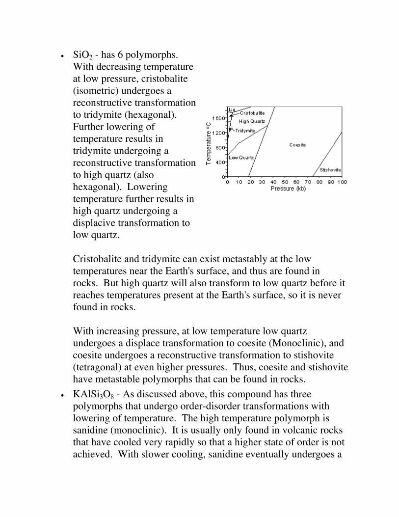
SiO2 - has 6 polymorphs.
With decreasing temperature
at low pressure, cristobalite
(isometric) undergoes a
reconstructive transformation
to tridymite (hexagonal).
Further lowering of
temperature results in
tridymite undergoing a
reconstructive transformation
to high quartz (also
hexagonal). Lowering
temperature further results in
high quartz undergoing a
displacive transformation to
low quartz.
Cristobalite and tridymite can exist metastably at the low
temperatures near the Earth's surface, and thus are found in
rocks. But high quartz will also transform to low quartz before it
reaches temperatures present at the Earth's surface, so it is never
found in rocks.
With increasing pressure, at low temperature low quartz
undergoes a displace transformation to coesite (Monoclinic), and
coesite undergoes a reconstructive transformation to stishovite
(tetragonal) at even higher pressures. Thus, coesite and stishovite
have metastable polymorphs that can be found in rocks.
KAlSi3O8 - As discussed above, this compound has three
polymorphs that undergo order-disorder transformations with
lowering of temperature. The high temperature polymorph is
sanidine (monoclinic). It is usually only found in volcanic rocks
that have cooled very rapidly so that a higher state of order is not
achieved. With slower cooling, sanidine eventually undergoes a

transformation to orthoclase (also monoclinic), and orthoclase
eventually transforms to microcline (triclinic) with further slow
cooling.
Polytypism
Polytypism is a type of polymorphism wherein different polymorphs
exist in different domains of the same crystal. It has to do with the way
that individual layers are stacked within a crystal structure. Polytypism
has little geologic consequence, and will thus not be discussed further
here.
Metamict Minerals
Metamict minerals are minerals whose crystal structure has been
partially destroyed by radiation from contained radioactive elements.
The breakdown of the crystal structure results from bombardment of a
particles emitted by the decay of U and Th radioactive isotopes.
The mineral zircon (ZrSiO4) often has U and Th atoms substituting for
Zr in the crystals structure. Since U and Th have radioactive isotopes,
Zircon is often seen to occur in various stages of metamictization.
Mineraloids
By definition, a mineral has to have an ordered atomic arrangement, or
crystalline structure. There are some Earth materials that fit all other
parts of the definition of a mineral, yet do not have a crystalline
structure. Such compounds are termed amorphous (without form).
Some of these amorphous compounds are called mineraloids. These
usually form at low temperatures and pressures during the process of
chemical weathering and form mammillary, botryoidal, and stalactitic
masses with widely varying chemical compositions. Limonite

[FeO.(OH)
.nH2O] and allophane ( a hydrous aluminum silicate) are
good examples.
Others like volcanic glass and opal
(SiO2.nH2O) have short-range order
or domains wherein some
crystalline-like order exists.
Unlike crystalline minerals that
show sharp, well defined x-ray
diffraction peaks, these mineraloids
with short-range order show broad
diffraction peaks that give evidence
of the short-range order.
Pseudomorphism
Pseudomorphism is the existence of a mineral that has the appearance
of another mineral. Pseudomorph means false form. Pseudomorphism
occurs when a mineral is altered in such a way that its internal structure
and chemical composition is changed but its external form is
preserved. Three mechanisms of pseudomorphism can be defined:
1. Substitution. In this mechanism chemical constituents are
simultaneously removed and replaced by other chemical
constituents during alteration. An example is the replacement of
wood fibers by quartz to form petrified wood that has the outward
appearance of the original wood, but is composed of quartz.
Another example is the alteration of fluorite which forms
isometric crystals and is sometimes replaced by quartz during
alteration. The resulting quartz crystals look isometric, and are
said to be pseudomorphed after fluorite.
2. Encrustation. If during the alteration process a thin crust of a new

mineral forms on the surface of a preexisting mineral, then the
preexisting mineral is removed, leaving the crust behind, we say
that pseudomorphism has resulted from encrustation. In this case
the thin crust of the new mineral will have casts of the form of the
original mineral.
3. Alteration. If only partial removal of the original mineral and
only partial replacement by the new mineral has taken place, then
it is possible to have a the space once occupied entirely by the
original mineral be partially composed of the new mineral. This
results for example in serpentine pseudomorphed after olivine or
pyroxene, anhydrite (CaSO4) pseudomorphed after gypsum
(CaSO4.2H2O), limonite [FeO
.(OH)
.nH2O] after pyrite (FeS2), and
anglesite (PbSO4) after galena (PbS).
COMPILED BY
GDC HANDWARA

LECTURE NOTES
1ST
SEMESTER
UNIT 4
Introduction to Uniaxial Minerals
Uniaxial minerals are a class of anisotropic minerals that include all minerals that crystallize in the
tetragonal and hexagonal crystal systems. They are called uniaxial because they have a single optic
axis. Light traveling along the direction of this single optic axis exhibits the same properties as
isotropic materials in the sense that the polarization direction of the light is not changed by passage
through the crystal. Similarly, if the optic axis is oriented perpendicular to the microscope stage with
the analyzer inserted, the grain will remain extinct throughout a 360o rotation of the stage. The single
optic axis is coincident with the c-crystallographic axis in tetragonal and hexagonal minerals. Thus,
light traveling parallel to the c-axis will behave as if it were traveling in an isotropic substance
because, looking down the c-axis of tetragonal or hexagonal minerals one sees only equal length a-
axes, just like in isometric minerals.
Like all anisotropic substances, the refractive indices of uniaxial crystals varies between two
extreme values. For uniaxial minerals these two extreme values of refractive index are defined
as (or No) and (or Ne). Values between and are referred to as '.
Uniaxial minerals can be further divided into two classes. If the mineral is said have a
negative optic sign or is uniaxial negative. In the opposite case, where the mineral is
said to have a positive optic sign or is uniaxial positive.
The absolute birefringence of a uniaxial minerals is defined as | | (the absolute value of
the difference between the extreme refractive indices).
Double Refraction
All anisotropic minerals exhibit the phenomenon of double refraction. Only when the
birefringence is very high, however, is it apparent to the human eye. Such a case exists for the
hexagonal (and therefore uniaxial) mineral calcite. Calcite has rhombohedral cleavage which
means it breaks into blocks with parallelogram - shaped faces. If a clear rhombic cleavage block
is placed over a point and observed from the top, two images of the point are seen through the
calcite crystal. This is known as double refraction.
What happens is that when unpolarized light enters the crystal from below, it is broken into two
polarized rays that vibrate perpendicular to each other within the crystal.

One ray, labeled o in the figure shown here, follows Snell's Law,
and is called the ordinary ray, or o-ray. It has a vibration direction
that is perpendicular to the plane containing the c-axis and the path
of the ray. The other ray, labeled e in the figure shown here, does
not follow Snell's Law, and is therefore referred to as the
extraordinary ray, or e-ray. The e ray is polarized with light
vibrating within the plane containing the c-axis and the
propagation path of the ray.
Since the angle of incidence of the light is 0o, both rays should not be refracted when entering the
crystal according to Snell's Law, but the e-ray violates this law because it's angle of refraction is
not 0o, but is r, as shown in the figure. Note that the vibration directions of the e-ray and the o-ray
are perpendicular to each other. These directions are referred to as the privileged directions in the
crystal.
If one separates out the e-ray and the o-ray as shown here, it
can be seen that the o-ray has a vibration direction that is
perpendicular to the propagation direction. On the other
hand, the vibration direction of the e-ray is not
perpendicular to the propagation direction. A line drawn
that is perpendicular to the vibration direction of the e-ray is
called the wave normal direction. It turns out the wave
normal direction does obey Snell's Law, as can be seen by
examining the diagram of the calcite crystal shown above.
In the case shown, the wave normal direction would be
parallel to the o-ray propagation direction, which is
following Snell's Law.
Uniaxial Indicatrix
Just like in isotropic minerals, we can construct an indicatrix for uniaxial minerals. The uniaxial
indicatrix is constructed by first orienting a crystal with its c-axis vertical. Since the c-axis is also
the optic axis in uniaxial crystals, light traveling along the c-axis will vibrate perpendicular to the
c-axis and parallel to the refractive index direction. Light vibrating perpendicular to the c-axis
is associated with the o-ray as discussed above. Thus, if vectors are drawn with lengths
proportional to the refractive index for light vibrating in that direction, such vectors would define
a circle with radius . This circle is referred to as the circular section of the uniaxial indicatrix.

Light propagating along directions perpendicular to the c-axis or
optic axis is broken into two rays that vibrate perpendicular to each
other. One of these rays, the e-ray vibrates parallel to the c-axis or
optic axis and thus vibrates parallel to the refractive index. Thus, a
vector with length proportional to the refractive index will be larger
than or smaller than the vectors drawn perpendicular to the optic axis,
and will define one axis of an ellipse. Such an ellipse with the direction as one of its axes and the direction as its other axis is
called the Principal Section of the uniaxial indicatrix.
Light vibrating parallel to any direction associated with a refractive
index intermediate between and will have vector lengths
intermediate between those of and and are referred to as ' directions. Thus, the uniaxial indicatrix is seen to be an ellipsoid of revolution. Such an ellipsoid of
revolution would be swept out by rotating the ellipse of the principal section by 180o. Note that
there are an infinite number of principal sections that would cut the indicatrix vertically.
Light propagating along one of the ' directions is broken into two rays, one vibrates parallel to an
' direction and the other vibrates parallel to the direction. An ellipse that has an ' direction
and a direction as its axes is referred to as a random section of the indicatrix.
Optic Sign
Recall that uniaxial minerals can be divided into 2 classes based on the optic sign of the mineral.
If the optic sign is negative and the
uniaxial indicatrix would take the form of an
oblate spheroid. Note that such an indicatrix is
elongated in the direction of the stroke of a
minus sign.
If the optic sign is positive and the
uniaxial indicatrix would take the form of a
prolate spheroid. Note that such an indicatrix is
elongated in the direction of the vertical stroke
of a plus sign.

Application of the Uniaxial Indicatrix
The uniaxial indicatrix provides a useful tool for thinking about the vibration directions of light as
it passes through a uniaxial crystal. Just like crystallographic axes, we can move the indicatrix
anywhere in a crystal so long it is moved parallel to itself.
This is shown here for an imaginary tetragonal crystal. In this case
the optic sign of the mineral is positive, and the uniaxial indicatrix is
shown at the center of the crystal.
If the crystal is mounted on the microscope stage such that
the c-axis or optic axis is perpendicular to the stage, we can
move the indicatrix up to the top face of the crystal (face a)
and see that such light will be vibrating in the direction
even if we rotate the stage. Thus we will see the circular
section of the indicatrix.
If the crystal is mounted on the stage such that the c-axis is
parallel to the stage, we can move the indicatrix to one of the
side faces of the crystal (such as face c) and see that light
will be broken up into two rays, one vibrating parallel to the
direction and one vibrating parallel to the direction.
Thus we will see one of the principal planes of the indicatrix.
If the crystal is mounted on the stage such that the c-axis or optic axis is neither parallel to
or perpendicular to the stage, we can move the indicatrix to some random face that is not
parallel to or perpendicular to the c-axis (such as face b) and see that the light will be
broken into two perpendicular rays, one vibrating parallel to the direction and the other
vibrating perpendicular to an ' direction. Thus we will see one of the random sections of
the indicatrix.
We will next look at what we could observe for crystals oriented on the microscope stage for each
of the general orientations described above, beginning with the unique circular section.

Circular Section
If a crystal is mounted on the microscope stage with its optic axis oriented exactly perpendicular
to the stage, the circular section of the indicatrix can be imagined to be on the upper surface of the
crystal such as for the crystal face labeled a in the diagram above.
In this orientation the crystal behaves just like an isotropic mineral.
Light polarized in an E-W direction entering the
crystal from below remains polarized in an E-W
direction as it passes through the crystal.
Since light is vibrating parallel to an direction
for all orientations of the grain, no change in
relief would be observed as we rotate the
microscope stage.
A comparison of the refractive index of the grain
to that of the oil using the Becke line method
would allow for the determination of the
refractive index of the mineral.
With the analyzer inserted the grain would go
extinct and would remain extinct throughout a
360o rotation of the microscope stage, because
the light exiting the crystal will still be polarized
in an E-W direction.

Principal Section
If the mineral grain is oriented such that the optic axis is oriented parallel to the microscope stage,
then we can imagine the principal section of the indicatrix as being parallel to the top of the grain
such as would be the case for a crystal lying on face c in the diagram above.
In this case, the mineral will show birefringence for most orientations, unless one of the
privileged directions in the crystal is lined up with the E-W polarizing direction of the incident
light entering from below.
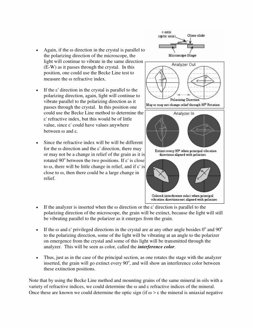
If the direction in the crystal is parallel to the
polarizing direction of the microscope, the light
will continue to vibrate in the same direction (E-
W) as it passes through the crystal. In this
position, one could use the Becke Line test to
measure the refractive index.
If the direction in the crystal is parallel to the
polarizing direction, again, light will continue to
vibrate parallel to the polarizing direction as it
passes through the crystal. In this position one
could use the Becke Line method to determine the
refractive index.
Since the refractive index will be will be different
for the direction and the direction, there will
be some change in relief of the grain as it is
rotated 90o between the two positions. How much
change in relief would also depend on the
birefringence of the mineral (|- |).
If the analyzer is inserted when the direction or
the direction is parallel to the polarizing
direction of the microscope, the grain will be
extinct, because the light will still be vibrating
parallel to the polarizer as it emerges from the
grain.
If the and privileged directions in the crystal are at any other angle besides 0
o and 90
o
to the polarizing direction, some light of the light will be vibrating at an angle to the
polarizer on emergence from the crystal and some of this light will be transmitted through
the analyzer. This will be seen as color, called the interference color.

Thus, as one rotates the stage with the analyzer inserted, the grain will go extinct every
90o, and will show an interference color between these extinction positions. The origin
and significance of the interference colors will be discussed in the next lecture.
Random Section
If the mineral grain is oriented such that the optic axis is oriented at an angle to the microscope
stage, then we can imagine a random section of the indicatrix as being parallel to the top of the
grain such as would be the case for a crystal lying on face b in the crystal diagram above.
In this case, the mineral will also show birefringence for most orientations, unless one of the
privileged directions in the crystal is lined up with the E-W polarizing direction of the incident
light entering from below But this time, one of the privileged directions corresponds to the
direction and the other to an ' direction in the crystal.
Again, if the direction in the crystal is parallel to
the polarizing direction of the microscope, the
light will continue to vibrate in the same direction
(E-W) as it passes through the crystal. In this
position, one could use the Becke Line test to
measure the refractive index.
If the ' direction in the crystal is parallel to the
polarizing direction, again, light will continue to
vibrate parallel to the polarizing direction as it
passes through the crystal. In this position one
could use the Becke Line method to determine the
' refractive index, but this would be of little
value, since ' could have values anywhere
between and .
Since the refractive index will be will be different
for the direction and the ' direction, there may
or may not be a change in relief of the grain as it is
rotated 90o between the two positions. If ' is close
to , there will be little change in relief, and if ' is
close to , then there could be a large change in
relief.
If the analyzer is inserted when the direction or the ' direction is parallel to the
polarizing direction of the microscope, the grain will be extinct, because the light will still
be vibrating parallel to the polarizer as it emerges from the grain.
If the and ' privileged directions in the crystal are at any other angle besides 0o and 90
o
to the polarizing direction, some of the light will be vibrating at an angle to the polarizer
on emergence from the crystal and some of this light will be transmitted through the
analyzer. This will be seen as color, called the interference color.
Thus, just as in the case of the principal section, as one rotates the stage with the analyzer
inserted, the grain will go extinct every 90o, and will show an interference color between
these extinction positions.
Note that by using the Becke Line method and mounting grains of the same mineral in oils with a
variety of refractive indices, we could determine the and refractive indices of the mineral.
Once these are known we could determine the optic sign (if > the mineral is uniaxial negative

or if > , the mineral is uniaxial positive), and the birefringence of the mineral (| - |). But,
this would be a time consuming operation and would be difficult.
It would be less difficult in the case where the grain is either elongated in the direction of the c-
axis or has a cleavage parallel to the c-axis (such as {110}, {100}, {010}, or {10 0}). In these
cases one could more easily keep track of which direction is associated with (the direction
perpendicular to the c-axis) and which direction is associated with (the direction parallel to the
c-axis).
Fortunately, there are other means to determine optic sign and birefringence that are less time
consuming. We will learn about these other means in the next lecture. Nevertheless, in lab you
will have to determine both refractive indices on a uniaxial mineral as an aid to learning the
concepts involved.
COMPILED BY
GDC HANDWARA
LECTURE NOTES
1ST
SEMESTER
UNIT 4
Biaxial Minerals
All minerals that crystallize in the orthorhombic, monoclinic, or triclinic crystal systems are
biaxial. Biaxial crystals have 2 optic axes, and this distinguishes biaxial crystals from uniaxial
crystals. Like uniaxial crystals, biaxial crystals have refractive indices that vary between two
extremes, but also have a unique intermediate refractive index. Biaxial refractive indices are as
follows:
The smallest refractive index is given the symbol (or X).
The intermediate refractive index is given the symbol (or Y).
The largest refractive index is given the symbol (or Z)
All biaxial minerals have optical symmetry equivalent to 2/m2/m2/m. But, in each of the
crystal systems, the optical directions have different correspondence to the crystallographic
directions.
In orthorhombic crystals the optical directions correspond to the crystallographic axes,
i.e. the X direction and its corresponding refractive index, can be either the a, b, or c
crystallographic axes, the Y direction and can be parallel to either a, b, or c, and the Z
direction or , can be parallel to either a, b, or c.
In monoclinic crystals, one of the X (), Y (), or Z () directions or indices is parallel
to the b crystallographic axis, and the other two do not coincide with crystallographic
directions.
In triclinic crystals none of the optical directions or indices coincide with
crystallographic directions, although in some rare case one of the indices might coincide
with one of the crystallographic directions.
The Biaxial Indicatrix
The biaxial indicatrix, like the isotropic and uniaxial indicatrices, diagrammatically illustrates

the refractive index for vibration directions of light. It is shown in the diagram below.
The biaxial indicatrix has three principle axes, labeled , , and .
Directions that have refractive indices between and , are referred to
as '. Directions with refractive indices between and are referred to
as '. Note that the direction also must occur in the plane that
includes and . Similarly, if we were to draw all other possible
planes that include the direction, would have to occur in each of
these as well. This results in two sections that would be circular with a
radius equivalent to the refractive index. These two sections are
referred to as the circular sections. In the diagrams below we see the
two circular sections, each having a radius equal to the refractive
index.
In the left-hand diagram some of
the other possible planes that
include are shown. In the right-
hand diagram these planes are
removed to show only the circular
sections. Lines drawn
perpendicular to the circular
sections are the optic axes. This is
why minerals that exhibit these
optical properties are called
biaxial.
The acute angle between the optic
axes is called the 2V angle.
Just like in uniaxial minerals, if one is looking down one of the optic axes, light traveling along
the optic axis will be vibrating in the direction, and thus the mineral would be extinct for all
rotation positions.
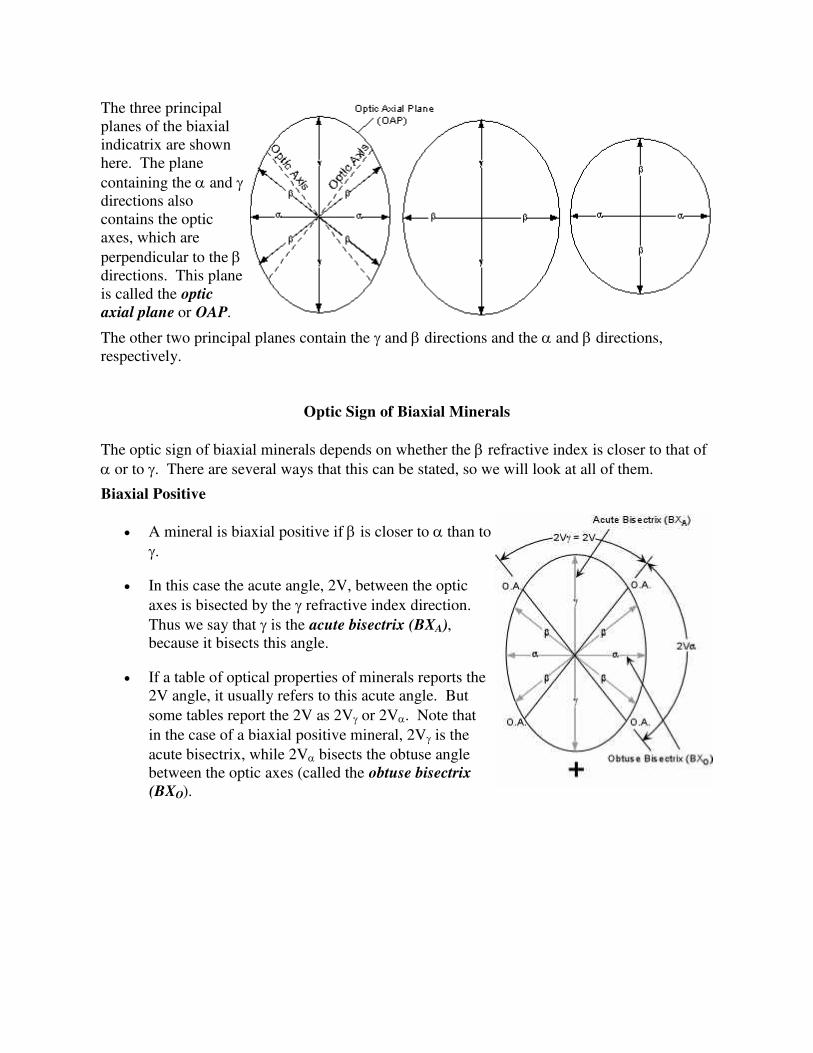
The three principal
planes of the biaxial
indicatrix are shown
here. The plane
containing the and
directions also
contains the optic
axes, which are
perpendicular to the
directions. This plane
is called the optic
axial plane or OAP.
The other two principal planes contain the and directions and the and directions,
respectively.
Optic Sign of Biaxial Minerals
The optic sign of biaxial minerals depends on whether the refractive index is closer to that of
or to . There are several ways that this can be stated, so we will look at all of them.
Biaxial Positive
A mineral is biaxial positive if is closer to than to
.
In this case the acute angle, 2V, between the optic
axes is bisected by the refractive index direction.
Thus we say that is the acute bisectrix (BXA),
because it bisects this angle.
If a table of optical properties of minerals reports the
2V angle, it usually refers to this acute angle. But
some tables report the 2V as 2V or 2V. Note that
in the case of a biaxial positive mineral, 2V is the
acute bisectrix, while 2V bisects the obtuse angle
between the optic axes (called the obtuse bisectrix
(BXO).

Biaxial Negative
A mineral is biaxial negative if is closer to
than to .
In this case the acute angle, 2V, between the
optic axes is bisected by the refractive
index direction. Thus we say that is the
acute bisectrix.
In the case of a biaxial negative mineral,
2V is the acute bisectrix, while 2V is the
obtuse bisectrix.
Note that 2V+ 2V = 180o.
If 2V = 90o the mineral has no optic sign.
If 2V = 0o the mineral is uniaxial.
Optical Orientations of Biaxial Crystals
Just like in uniaxial crystals, we can move the indicatrix around in a crystal so long as the
indicatrix is kept parallel to the optical directions, and use this as an aid to determining the
optical directions in the crystal. Several orientations are possible, the most general are shown
in the diagram below. Note that in this diagram we have not shown the crystallographic axes,
because different minerals will show different relationships between optical directions and
crystallographic directions as discussed above.
If a crystal oriented on the microscope stage with its vibration direction perpendicular
to the stage, then the and vibration directions will be the two privileged directions in
the crystal, as for the face labeled A in the diagram below. With such a face it would be
possible to determine the and refractive indices by using the Becke line method and
various oils when either of these privileged directions is oriented parallel to the
polarizer. Just as in uniaxial minerals, the crystal would be extinct with the analyzer
inserted when either of the privileged directions are parallel to the polarizer. At any
other orientation of the two principal vibration directions the crystal would exhibit an
interference color that reflects the thickness of the crystal and the birefringence for this
orientation ( - ). Note that this would not be the maximum interference color for this
crystal.

If a crystal face such as B in the diagram above is parallel to the microscope stage, one
would be looking down the direction in the crystal. In this orientation the optic axial
plane (OAP) would be parallel to the stage, and the and refractive indices could be
determined using the Becke line method and various oils. Because the direction in
this orientation is perpendicular to or normal to the OAP, the direction is often
referred to as the optic normal direction (O.N.).
In this orientation the interference color exhibited by positions off of extinction would
again reflect the thickness of the crystal and the birefringence. But the birefringence for
this orientation would be the absolute or maximum birefringence possible for this
crystal ( - ).
If a face like C were lying parallel to the stage, it would show another of the principal
planes of the indicatrix, this time showing the and vibration directions of the
crystal. Again, the refractive indices corresponding the and could be determined in
this orientation. Note that for crystal faces A or C, we would be looking down either
the BXA or BXO depending on the optic sign of the mineral. The interference color seen
with the analyzer inserted will reflect an intermediate birefringence for the crystal ( -
).
If a face like D were lying parallel to the stage, it would show the circular section and

one of the optic axes would be orientated perpendicular to the stage. For this
orientation the crystal would show no change in relief on rotation of the stage with the
analyzer not inserted, and would remain extinct through a 360o rotation with crossed
polarizers. For any rotation position the refractive index could be determined.
Faces like E and F, if lying parallel to the stage, would have privileged directions
corresponding to random vibration directions. ', ' and could be measured, but this
would be of little use because all of these refractive indices are intermediate.
While knowledge of the optical directions can provide a means to measure the principle
refractive indices, this is not often done because much of the information necessary to identify
a biaxial mineral can be obtained from interference figures.
Biaxial Interference Figures
Four primary types of biaxial interference are seen. Only two of these are commonly used, but
it is essential to discuss all four so that you can recognize each.
Acute Bisectrix Figure (BXA)
Looking down the acute bisectrix, (the direction perpendicular to the stage if the crystal is
optically positive, or the direction perpendicular to the stage if the crystal is negative), at 45o
off extinction in conoscope mode, one would see the interference figure shown in the left-hand
diagram below.
The dark isogyres mark the positions where light vibrating parallel to the polarizer has
passed through the crystal.
At the points of maximum curvature of the isogyres are the two melatopes that mark the
positions where rays that traveled along the optic axis emerge from the field of view.
Note that the distance between the two melatopes is proportional to the angle 2V
between the optic axes.
Also seen are isochromes, which show increasing interference colors in all directions
away from the melatopes. The number of isochromes and maximum order of the
interference colors seen will increase with increasing thickness and absolute
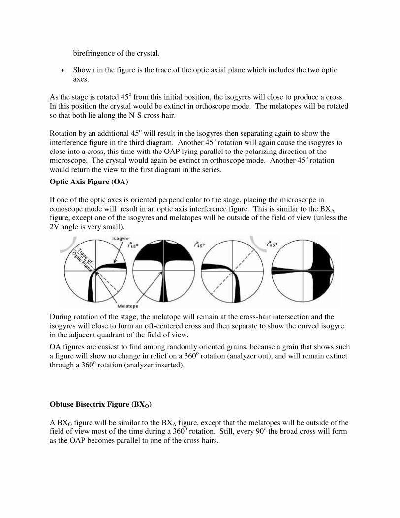
birefringence of the crystal.
Shown in the figure is the trace of the optic axial plane which includes the two optic
axes.
As the stage is rotated 45o from this initial position, the isogyres will close to produce a cross.
In this position the crystal would be extinct in orthoscope mode. The melatopes will be rotated
so that both lie along the N-S cross hair.
Rotation by an additional 45o will result in the isogyres then separating again to show the
interference figure in the third diagram. Another 45o rotation will again cause the isogyres to
close into a cross, this time with the OAP lying parallel to the polarizing direction of the
microscope. The crystal would again be extinct in orthoscope mode. Another 45o rotation
would return the view to the first diagram in the series.
Optic Axis Figure (OA)
If one of the optic axes is oriented perpendicular to the stage, placing the microscope in
conoscope mode will result in an optic axis interference figure. This is similar to the BXA
figure, except one of the isogyres and melatopes will be outside of the field of view (unless the
2V angle is very small).
During rotation of the stage, the melatope will remain at the cross-hair intersection and the
isogyres will close to form an off-centered cross and then separate to show the curved isogyre
in the adjacent quadrant of the field of view.
OA figures are easiest to find among randomly oriented grains, because a grain that shows such
a figure will show no change in relief on a 360o rotation (analyzer out), and will remain extinct
through a 360o rotation (analyzer inserted).
Obtuse Bisectrix Figure (BXO)
A BXO figure will be similar to the BXA figure, except that the melatopes will be outside of the
field of view most of the time during a 360o rotation. Still, every 90
o the broad cross will form
as the OAP becomes parallel to one of the cross hairs.
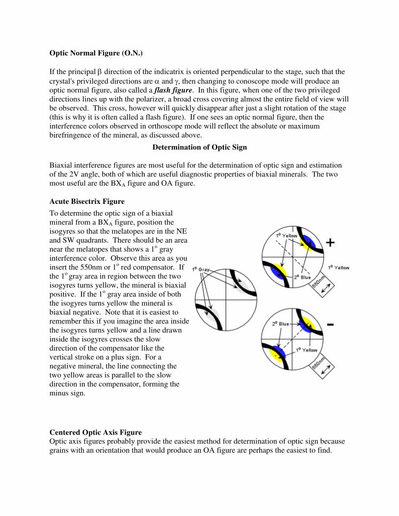
Optic Normal Figure (O.N.)
If the principal direction of the indicatrix is oriented perpendicular to the stage, such that the
crystal's privileged directions are and , then changing to conoscope mode will produce an
optic normal figure, also called a flash figure. In this figure, when one of the two privileged
directions lines up with the polarizer, a broad cross covering almost the entire field of view will
be observed. This cross, however will quickly disappear after just a slight rotation of the stage
(this is why it is often called a flash figure). If one sees an optic normal figure, then the
interference colors observed in orthoscope mode will reflect the absolute or maximum
birefringence of the mineral, as discussed above.
Determination of Optic Sign
Biaxial interference figures are most useful for the determination of optic sign and estimation
of the 2V angle, both of which are useful diagnostic properties of biaxial minerals. The two
most useful are the BXA figure and OA figure.
Acute Bisectrix Figure
To determine the optic sign of a biaxial
mineral from a BXA figure, position the
isogyres so that the melatopes are in the NE
and SW quadrants. There should be an area
near the melatopes that shows a 1o gray
interference color. Observe this area as you
insert the 550nm or 1o red compensator. If
the 1o gray area in region between the two
isogyres turns yellow, the mineral is biaxial
positive. If the 1o gray area inside of both
the isogyres turns yellow the mineral is
biaxial negative. Note that it is easiest to
remember this if you imagine the area inside
the isogyres turns yellow and a line drawn
inside the isogyres crosses the slow
direction of the compensator like the
vertical stroke on a plus sign. For a
negative mineral, the line connecting the
two yellow areas is parallel to the slow
direction in the compensator, forming the
minus sign.
Centered Optic Axis Figure
Optic axis figures probably provide the easiest method for determination of optic sign because
grains with an orientation that would produce an OA figure are perhaps the easiest to find.

The method is similar to the BXA figure,
except you will be looking at only one of the
isogyres. Again place the isogyre so that the
inside of the isogyre is in the NW quadrant.
Find the area that shows 1o gray close to the
melatope. Observe this area as the 550 nm
compensator plate is inserted. If the area
outside of the isogyre turns yellow, the
mineral is biaxial positive. If the area inside
the isogyre turns yellow, the mineral is biaxial
negative.
Off-centered Figures
Probably even easier to locate are off-centered OA or BXA interference figures.
The method for optic sign determination in
off-centered figures is essentially the same as
for BXA and OA figures. Position the
isogyres so that it fits best in either the NE or
SW quadrant. Observe the gray area near the
melatopes and note the color change on
insertion of the 550 nm compensator. If the
gray area outside the isogyre turns yellow, the
mineral is biaxial positive. If the gray area
outside isogyre turns blue and the gray area
inside the isogyre turns yellow, the mineral is
biaxial negative.
How to Locate Different types of Biaxial Interference Figures
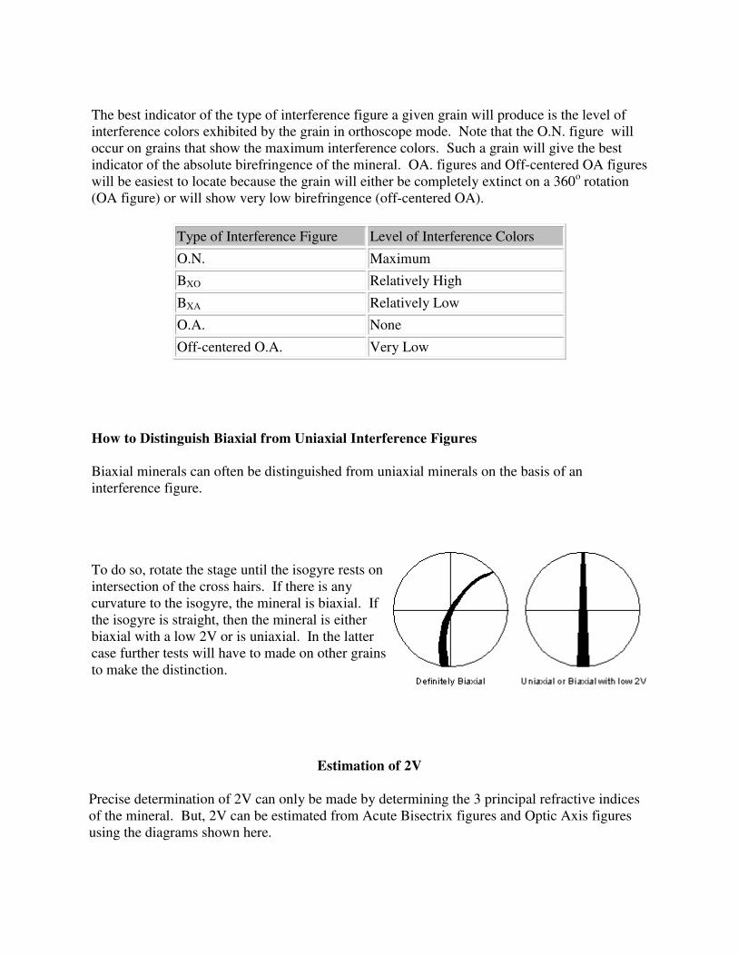
The best indicator of the type of interference figure a given grain will produce is the level of
interference colors exhibited by the grain in orthoscope mode. Note that the O.N. figure will
occur on grains that show the maximum interference colors. Such a grain will give the best
indicator of the absolute birefringence of the mineral. OA. figures and Off-centered OA figures
will be easiest to locate because the grain will either be completely extinct on a 360o rotation
(OA figure) or will show very low birefringence (off-centered OA).
Type of Interference Figure Level of Interference Colors
O.N. Maximum
BXO Relatively High
BXA Relatively Low
O.A. None
Off-centered O.A. Very Low
How to Distinguish Biaxial from Uniaxial Interference Figures
Biaxial minerals can often be distinguished from uniaxial minerals on the basis of an
interference figure.
To do so, rotate the stage until the isogyre rests on
intersection of the cross hairs. If there is any
curvature to the isogyre, the mineral is biaxial. If
the isogyre is straight, then the mineral is either
biaxial with a low 2V or is uniaxial. In the latter
case further tests will have to made on other grains
to make the distinction.
Estimation of 2V
Precise determination of 2V can only be made by determining the 3 principal refractive indices
of the mineral. But, 2V can be estimated from Acute Bisectrix figures and Optic Axis figures
using the diagrams shown here.
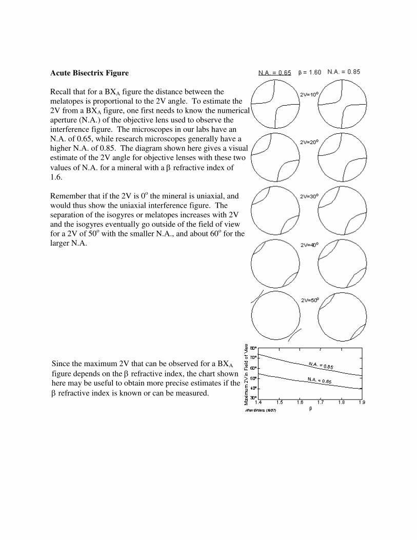
Acute Bisectrix Figure
Recall that for a BXA figure the distance between the
melatopes is proportional to the 2V angle. To estimate the
2V from a BXA figure, one first needs to know the numerical
aperture (N.A.) of the objective lens used to observe the
interference figure. The microscopes in our labs have an
N.A. of 0.65, while research microscopes generally have a
higher N.A. of 0.85. The diagram shown here gives a visual
estimate of the 2V angle for objective lenses with these two
values of N.A. for a mineral with a refractive index of
1.6.
Remember that if the 2V is 0o the mineral is uniaxial, and
would thus show the uniaxial interference figure. The
separation of the isogyres or melatopes increases with 2V
and the isogyres eventually go outside of the field of view
for a 2V of 50o with the smaller N.A., and about 60
o for the
larger N.A.
Since the maximum 2V that can be observed for a BXA
figure depends on the refractive index, the chart shown
here may be useful to obtain more precise estimates if the
refractive index is known or can be measured.

Optic Axis Figure
2V estimates can be made on an optic axis figure by noting the
curvature of the isogyres and referring to the diagram shown here.
Note that the curvature is most for low values of 2V and decreases
to where the isogyre essentially forms a straight line across the
field of view for a 2V of 90o. For a 2V of 0
o the mineral is
uniaxial and the isogyres form a cross with straight isogyres.
COMPILED BY
GDC HANDWARA