tridas lhcc report cms level 1 trigger - university of …wsmith/cms/lhcc_jan99.pdf · wesley...
TRANSCRIPT

Wesley Smith, U. Wisconsin January, 1999
TriDAS LHCC ReportTriDAS LHCC ReportCMS Level 1 TriggerCMS Level 1 Trigger
Wesley Smith, U. Wisconsin, 19.1.99
Overview & Recent Progress:• Calorimeter Trigger• Muon Trigger• Global Trigger
Organization, Cost, Schedule
The pdf file of this talk is available at:http://cmsdoc.cern.ch/~wsmith/LHCC_Jan99.pdfSee also CMS Level 1 Trigger Home page at
http://cmsdoc.cern.ch/ftp/afscms/TRIDAS/html/level1.html

Wesley Smith, U. Wisconsin January, 1999
Detector Frontend
Computing Services
Readout
FilterFarms
Event Flow
Control Readout Network
Level 1Trigger
Controls
40 MHz
105 Hz
102 Hz
100 Tbyte/s
100 Gbyte/s
100 Mbyte/s
Collision rate 40 MHzLevel-1 Maximum trigger rate 100 kHzAverage event size ≈ 1 MbyteNo. of In-Out units (200-5000 byte/event) 1000Readout network (512-512 switch) bandwidth ≈ 500 Gbit/s Event filter computing power ≈ 5 106 MIPSData production ≈ Tbyte/dayNo. of readout crates ≈ 250No. of electronics boards ≈ 10000
CMS Trigger & DAQCMS Trigger & DAQ
Basic Structure
Wesley Smith, U. Wisconsin January, 1999
•
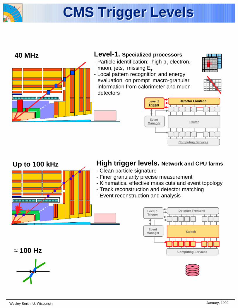
High trigger levels. Network and CPU farms- Clean particle signature- Finer granularity precise measurement- Kinematics. effective mass cuts and event topology- Track reconstruction and detector matching- Event reconstruction and analysis
Level-1. Specialized processors- Particle identification: high pT electron,
muon, jets, missing ET
- Local pattern recognition and energy evaluation on prompt macro-granular information from calorimeter and muon detectors
40 MHz
Up to 100 kHz
≈ 100 Hz
Detector Frontend
Computing Services
Event Manager Switch
Level 1Trigger
Detector Frontend
Computing Services
Event Manager Switch
Level 1Trigger
CMS Trigger LevelsCMS Trigger Levels
•
• •• ••
•

Wesley Smith, U. Wisconsin January, 1999
Synchronous 40 MHz digital system
- 160 MHz internal pipeline
- Readout and processing latency < 1µs
- Signal distribution latency ≈ 2 µs
Global Trigger 1
Accept/Reject LV-1
Trigger Primitive Generator
Front-End Digitizer
Local level-1Primitive e, γ, jets, µ
Pipeline delay ( ≈ 3 µs)
≈ 3 µs latency
loop
Level-1 trigger systemLevel-1 trigger system
Communication Loop:

Wesley Smith, U. Wisconsin January, 1999
Level 1 LatencyLevel 1 Latency
RPC DT CSC CALO
detector
CALOtrigger
global trigger
clk/control
local clk/control
RPCPACT
M. Kudla
J. Ero
J. Hauser W. Smith
link to detector~ 18 bx
W. Smith
linklin
k
R. Martinelli
logicalunitsinterconnections between logical units
links between detector and control room (18 bx)
66 bx
=>28 bx
126 bx
A. Taurok
5 bx5bx
frontend frontend frontend frontend
DTTPG
CSCTPG
CALOTPG
TRACKFINDERS
DT
global muon trigger79 bx
74 bx
80 bx
link
link
92 bx
A. Taurok
98 bx
77 bx
CSC
D. Acosta

Wesley Smith, U. Wisconsin January, 1999
CMS/LHC Trigger PhysicsCMS/LHC Trigger Physics
Standard model Higgs (high luminosity)
• H (80 GeV) → γ γ • H (120 GeV) → Z Z* (4 leptons)
• H (>500 GeV) → leptons ( + ν's)
• H (< 2MW Associated t or W or Z) → b b (lepton + X) SUSY Higgs (low luminosity)
• (standard model Higgs like channels)
• h, H, A → τ τ (lepton + X) or → µµ• A → Z h ; h → bb (lepton + X)
• p p → t t X; t → H+ b; H+ → τ ν; t → lepton + X; τ → X SUSY sparticle searches (low luminosity)
• MSSM sparticle → LSP (Missing Et) + n jets
• MSSM sparticle → Same sign dileptons + X Other new particles
• Z' → dileptons
• Leptoquarks: dileptons Top physics (low luminosity)
• t → lepton + X
• t → multijets Bottom physics (low luminosity)
• b → lepton + X
• b → ψks (leptons + X) QCD
• Low luminosity 100 GeV jets
• High luminosity 200 GeV jets ⇒ Trigger candidate requirements:
• High luminosity: lepton/γ (30 GeV), dileptons/γγ (15 GeV) missing Et (100 GeV), jets (200 GeV)
• Low luminosity: lepton/γ (15 GeV), dileptons/γγ (10 GeV) missing Et (50 GeV), jets (100 GeV)

Wesley Smith, U. Wisconsin January, 1999
Cal. Trigger requirementsCal. Trigger requirements Input
• ECAL trigger towers, 0.087φ x 0.087η• Matching HCAL towers
• Data every 25ns - including any corrections for time development of calorimeter signal
• 8 bit transverse energy
• 1 bit finegrain charecterization of energy deposit
• Data presynchronized across all channels, ECAL and HCAL
Output
• Top 4 nonisolated electrons/photons (Et and location)
• Top 4 isolated electrons/photons (Et and location)
• Top 6 jets (Et and location) & no. above threshold
• Total and missing transverse energy (Et, Ex, Ey)
• Minimimum ionization ID and isolation bits for use with muon trigger
Outut rate
• 75/2=37.5 kHz maximum for calorimeter trigger
• Simulations should indicate significant safety margin - i.e., ~15 kHz rate from calorimeter trigger simulation
Efficiency
• Trigger should contribute no more than a few percent inefficiency for any physics channel compared to other offline analysis cuts.
• Trigger efficiencies should be measurable

Janu
ary,
199
9W
esle
y S
mith
, U. W
isco
nsin
HA
C V
eto0.
017
η
φη
Hit
0.08
7 η0.
087
φ
Max
Had
EM
Nei
ghbo
r E
M
Tow
er V
eto
0.01
7 φ
Ele
ctro
n:
4x4
Jet
Reg
ion
EC
AL
HC
AL
∆η,∆
φ =
0.34
8
Tri
gg
erT
ow
er
Jet:
Jet
Et f
rom
su
m o
f E
CA
L&
HC
AL
trig
ger
to
wer
Et in
no
n-o
verl
app
ing
4x4
re
gio
ns
(als
o u
sed
fo
r E
x, E
y, E
t, E
tMis
s )U
se m
ult
ijet
trig
ger
sJe
t ca
nd
idat
es a
re s
ort
ed t
o f
ind
hig
hes
t en
erg
y je
ts
3 x
3 sl
idin
g w
ind
ow
ce
nte
red
on
EC
AL
/HC
AL
tr
igg
er t
ow
er p
airs
To
wer
co
un
t =
72φ
x 60
η x
2 =
8640C
alo
rim
eter
Tri
gg
ers
Cal
ori
met
er T
rig
ger
s
Fin
e-G
rain
EM
Vet
o
Nei
ghbo
r H
AC
Vet
oE
M N
eigh
bor
FG
V
eto
Janu
ary,
199
9W
esle
y S
mith
, U. W
isco
nsinHig
h L
um
ino
sity
Cal
Tri
gg
erH
igh
Lu
min
osi
ty C
al T
rig
ger
Lu
min
osi
ty =
1034
cm
-2 s
-1
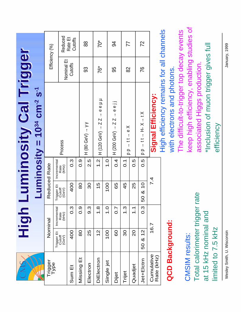
QC
D B
ackg
rou
nd
:
CM
SIM
res
ults
:T
otal
cal
orim
eter
trig
ger
rate
at
15
kHz
nom
inal
and
lim
ited
to 7
.5 k
Hz
Sig
nal
Eff
icie
ncy
:H
igh
effic
ienc
y re
mai
ns fo
r al
l cha
nnel
s w
ith e
lect
rons
and
pho
tons
.T
he d
iffic
ult-
to-t
rigge
r to
p de
cay
even
ts
keep
hig
h ef
ficie
ncy,
ena
blin
g st
udie
s of
as
soci
ated
Hig
gs p
rodu
ctio
n.*I
nclu
sion
of m
uon
trig
ger
give
s fu
ll ef
ficie
ncy
Trigger
Type
No
min
al
Re
du
ce
d R
ate
Tri
gg
er
Et
Cuto
ff(G
eV
)
Incre
menta
lR
ate
(kH
z)
Tri
gg
er
Et
Cuto
ff(G
eV
)
Incre
menta
lR
ate
(kH
z)
Su
m E
t4
00
0.3
40
00
.3
Mis
sin
g E
t8
00
.98
00
.9
Ele
ctr
on
25
9.3
30
2.5
DiE
lectr
on
12
1.8
15
1.2
Sin
gle
je
t1
00
1.0
10
01
.0
Dije
t60
0.7
65
0.4
Trije
t30
1.3
45
0.1
Quadje
t20
1.1
25
0.5
Je
t+E
lctr
n5
0 &
12
0.3
50
& 1
00
.5
Cum
ula
tive
Ra
te (
kH
z)
16.7
7.4
Pro
cess
Effi
cien
cy (%
)
Nom
inal
Et
Cut
offs
Red
uced
Rat
e E
tC
utof
fs
H (8
0 G
eV)→
γ γ
9388
H (1
20 G
eV)→
Z Z
→ e
eµ
µ76
*70
*
H (2
00 G
eV)→
Z Z
→ e
e j
j95
94
p p
→ t
t→ e
X82
77
p p
→ t
t→ H
+ X
→ t
X76
72
LEB
Wor
ksho
p, S
epte
mbe
r199
8W
esle
y S
mith
, U. W
isco
nsin
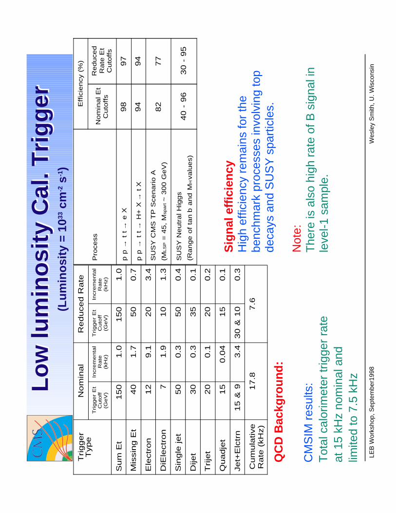
Sig
nal
eff
icie
ncy
Hig
h ef
ficie
ncy
rem
ains
for
the
benc
hmar
k pr
oces
ses
invo
lvin
g to
p de
cays
and
SU
SY
spa
rtic
les.
Not
e:T
here
is a
lso
high
rat
e of
B s
igna
l in
leve
l-1 s
ampl
e.
Lo
w lu
min
osi
ty C
al. T
rig
ger
Lo
w lu
min
osi
ty C
al. T
rig
ger
(Lu
min
osi
ty =
1033
cm
-2 s
-1)
Trigger
Type
No
min
al
Re
du
ce
d R
ate
Tri
gg
er
Et
Cuto
ff(G
eV
)
Incre
menta
lR
ate
(kH
z)
Tri
gg
er
Et
Cuto
ff(G
eV
)
Incre
menta
lR
ate
(kH
z)
Su
m E
t1
50
1.0
15
01
.0
Mis
sin
g E
t4
01
.75
00
.7
Ele
ctr
on
12
9.1
20
3.4
DiE
lectr
on
71.9
10
1.3
Sin
gle
je
t5
00
.35
00
.4
Dije
t30
0.3
35
0.1
Trije
t20
0.1
20
0.2
Quadje
t15
0.0
415
0.1
Je
t+E
lctr
n1
5 &
93
.43
0 &
10
0.3
Cum
ula
tive
Ra
te (
kH
z)
17.8
7.6
Pro
ce
ss
Eff
icie
ncy (
%)
No
min
al E
tC
uto
ffs
Re
du
ce
dR
ate
Et
Cu
toff
s
p p
→ t
t→
e X
98
97
p p
→ t
t→
H+
X→
t X
94
94
SU
SY
CM
S T
P S
ce
na
rio
A
(ML
SP =
45
, M
sp
art ~
30
0 G
eV
)82
77
SU
SY
Ne
utr
al H
igg
s
(Ra
ng
e o
f ta
nb
an
d M
H va
lue
s)
40
- 9
63
0 -
95
QC
D B
ackg
rou
nd
:
CM
SIM
res
ults
:T
otal
cal
orim
eter
trig
ger
rate
at
15
kHz
nom
inal
and
lim
ited
to 7
.5 k
Hz
Janu
ary,
199
9W
esle
y S
mith
, U. W
isco
nsin
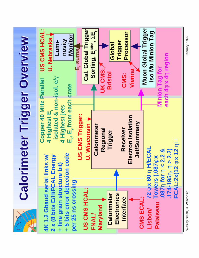
Cal
ori
met
erR
egio
nal
Tri
gg
er
Rec
eive
rE
lect
ron
Iso
lati
on
Jet/
Su
mm
ary
Cal
ori
met
er
Ele
ctro
nic
sIn
terf
ace
Glo
bal
T
rig
ger
P
roce
sso
r
Mu
on
Glo
bal
Tri
gg
erIs
o M
u M
inIo
n T
ag
Cal
. Glo
bal
Tri
gg
erS
ort
ing
, EtM
iss ,
ΣEt
Min
Ion
Tag
fo
rea
ch 4
φ x
4η r
egio
n
Co
pp
er 4
0 M
Hz
Par
alle
l4
Hig
hes
t E
t
iso
late
d &
no
n-i
sol.
e/γ
4 H
igh
est
jets
Ex,
Ey fr
om
eac
h c
rate
Et s
um
s
Lu
mi-
no
sity
Mo
nit
or
4K 1
.2 G
bau
d s
eria
l lin
ks w
/2
x (8
bit
s E
/H/F
CA
L E
ner
gy
+ fi
ne
gra
in s
tru
ctu
re b
it)
+ 5
bit
s er
ror
det
ecti
on
co
de
per
25
ns
cro
ssin
g
Cal
ori
met
er T
rig
ger
Ove
rvie
wC
alo
rim
eter
Tri
gg
er O
verv
iew
US
CM
S T
rig
ger
:U
. Wis
con
sin
US
CM
S H
CA
L:
FN
AL
/M
aryl
and
CM
S E
CA
L:
Lis
bo
n/
Pal
aise
au
US
CM
S H
CA
L:
U. N
ebra
ska
UK
CM
S:
Bri
sto
l
CM
S:
Vie
nn
a
72 φ
x 6
0 η
H/E
CA
LT
ow
ers
(.08
7φ x
.087
η fo
r η
< 2.
2 &
.174
-195
η, η
> 2
.2)
FC
AL
:2x(
12 φ
x 1
2 η)
E
CA
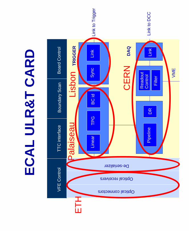
L U
LR
&T
CA
RD
VF
E C
ontr
olT
TC
inte
rfac
eB
ound
ary
Sca
nB
oard
Con
trol
Line
arT
PG
BC
idS
ync
Link
Pip
elin
e
Rea
dout
Con
trol
Link
Optical connectors
Optical receivers
De-serializer
TR
IGG
ER
DA
Q
VM
E
Link
to D
CC
Link
to T
rigge
r
DR
Filt
er
Lisb
onP
alai
seau
ET
H
CE
RN
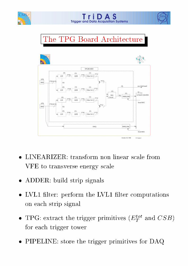
October 28, 1998
5*12
5*12
TPG(1)
PIPELINE24
from ROC
LIN ADD Filter lvl-1
LIN ADD Filter lvl-11*12
1*12
(5) (1) (1)
LIN ADD Filter lvl-1
LIN ADD Filter lvl-11*12
1*12
(1) (1)
5*5(14+2)
from ROC
5*18 1*18
5*18 1*18
5*18 1*18
5*18 1*18
DAQ
(5) (1) (1)
(5)
(5) (1) (1)
(1)
TPGBOARD
Circuit
32
to board controller
out_link board24
PIPELINE
DES
(25)
DES
(25)5*5(14+2)
X5
X5
file=tpgupper

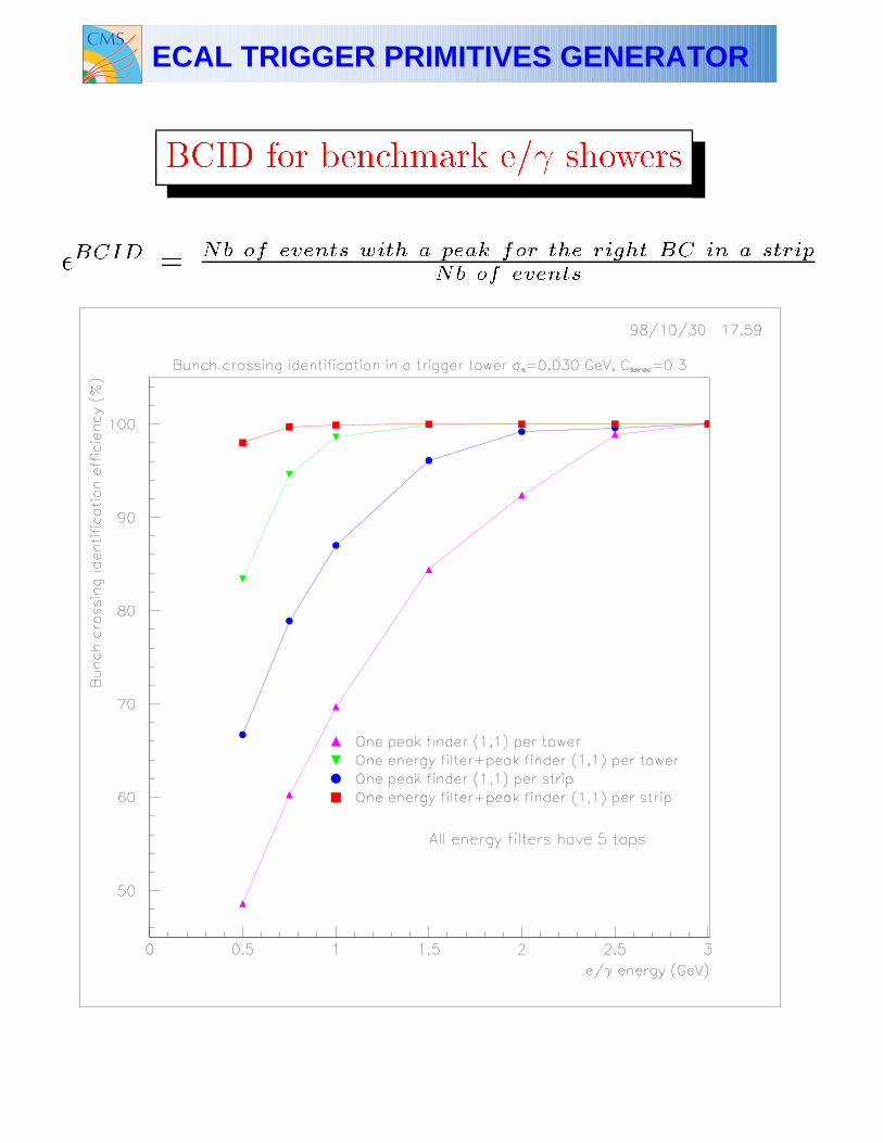
ECAL TRIGGER PRIMITIVES GENERATOR
BCID for benchmark e/ showers
�BCID = Nb of events with a peak for the right BC in a strip
Nb of events

Sync FIFO
• 2 Input Channels with time differenceand same Output Timing
Ch#1 Input
Ch#1 Output
Ch#2 Input
Ch#2 Output

Sync Tester Board

Sync Block Diagram
Differences from previous design:• Merge of the 2 circuits.• TTC Control Signals decoded on the BC.• Internal Accumulator.• FIFO Transparent Mode with programmable depth.• Latency Register (Tx_BC0 > Rx_BC0 distance).• BIST.

Wesley Smith, U. Wisconsin January, 1999
{20o{∆φ=5o
0.0
00
0.0
87
0.1
74
0.2
61
0.3
48
0.4
35
0.5
22
0.6
09
0.6
96
0.7
83
0.8
70
0.9
57
1.0
44
1.1
31
1.2
18
1.3
05
1.3
92
1.4
79
EB EE
{ ∆η=
0.0
87
{ {
{One RegionalTrigger Crate
1.5
66
1.6
53
1.7
40
1.8
27
1.9
14
2.0
01
2.0
88
2.1
75
2.2
62
2.4
36
2.6
10
{ { ∆η=
0.1
74
{ ∆η=
0.1
74
1 2 3 4 5 6 7 8 9 10 1211 13 14 15 16 17 1918 20 21 22 23 24 25 26 27 28
3.0
00
{ ∆η=
0.1
95
∆η=
0.0
87
{ ∆η=
0.1
95
29
HBHE{
Overlap
ReceiverCard
30
2.8
05
with 8 receiver cards
Calorimeter Trigger TowersCalorimeter Trigger Towers
η=2.436η=2.262η=2.175η=2.088η=2.001η=1.914η=1.827η=1.740η=1.653η=1.566η=1.479
η=1.392η=1.
305
η=1.
218
η=1.
131
η=1.
044
η=0.
957
η=0.
870
η=0.
783
η=0.
609
η=0.
695
η=0.
522
η=0.
435
η=0.
348
η=0.
261
η=0.
174
η=0.
087
η=0.
000
η=2.805
Scale
(meters)
0 1.00.5
4.33
2 m
5.68
0 m
2.93
5 m
3.90
0 m
1.290 m
1.811 m
2.900 m
η=3.000
1 2 3 4 5 6 7 8 9 10 12 13 14 15 16 17
18
19
20212223242526272829
11
30
η=2.610Tracker
EB/1
EE/1
HE/1
HB/1
2 x 9 x

Janu
ary,
199
9W
esle
y S
mith
, U. W
isco
nsin
Reg
ion
al C
alo
rim
eter
Cra
teR
egio
nal
Cal
ori
met
er C
rate
Dat
a fr
om
cal
ori
met
er F
E o
n C
u li
nks
@ 1
.2 G
bau
d
•Int
o 15
2 re
ar-m
ount
ed R
ecei
ver
Car
ds
160
MH
z p
oin
t to
po
int
bac
kpla
ne
•19
Clo
ck&
Con
trol
, 152
Ele
ctro
n Id
entif
icat
ion,
19 J
et/S
umm
ary,
Rec
eive
r C
ards
ope
rate
@ 1
60 M
Hz
Ele
ctro
n
ID C
ard
Bac
kpla
ne
Rec
eive
r C
ard
VM
E
C O N T R O L L E R
M O N I T O R
EI
EI
EI
EI
EI
EI
EI
EI
JSL T T C
Jet
Su
mm
ary
Car
d
19 X
(18
E/H
CA
L+
1 F
CA
L)

Janu
ary,
199
9W
esle
y S
mith
, U. W
isco
nsin
Inte
r C
rate
Cab
les
& S
tag
ing
Dat
a fr
om
Rea
r @
120
MH
z T
TL
Ph
ase
AS
IC:
Des
kew
,Mu
x @
160
MH
z E
rro
r b
it f
or
each
4x4
, Tes
t V
ecto
rsM
emo
ry L
UT
@ 1
60 M
Hz
Ad
der
AS
IC:
8 in
pu
ts @
160
MH
z in
25
ns.
D
iffe
ren
tial
Ou
tpu
t@16
0 M
Hz
LU
Ts
V
ME
Inte
rfac
e
Bn
dry
Sca
n &
Sel
f T
est
Ph
ase
Ph
ase
Ph
ase
Ph
ase
Ph
ase
Ph
ase
Ph
ase
Ph
ase
Ad
der
Ad
der
Ad
der
C L O C K D I S T R I B U T I O N
M E M O R Y S U P P O R T
Sta
gin
g &
Bac
kpla
ne
Dri
vers
Rec
eive
r C
ard
Rec
eive
r C
ard
Rea
r: 3
2 C
han
nel
s =
4 C
h. x
8 m
ezza
nin
e ca
rds
1.2
GB
aud
co
pp
er r
cvrs
18
bit
(2x
9) d
ata
+ 5
bit
err
or
Vit
esse
Ch
ip:
C
on
vert
s S
eria
l to
Par
alle
l
Fro
nt:
DC
/DC
3.3
V
EQ
Un
der
-bo
ard
co
nn
ecto
rs
Cab
le
Eq
ual
izat
ion
(2 c
ircu
its
on
fro
nt
& b
ack)
VM
E
Co
ntr
ol
AM
P S
trip
line
Hig
h D
ensi
ty
Co
nn
ecto
r
DC
-to
-DC
C
on
vert
erM
ezza
nin
e C
ard
des
ign
by
J. L
acke
y
V 7214
EQ
EQ
EQ
EQ
EQ
EQ
EQ
EQ
EQ
EQ
EQ
EQ
EQ
EQ
EQ
EQ
Vit
esse
In
terc
on
nec
t C
hip
po
wer
si
gn
als
9U x
400
mm
V 7214
V 7214
V 7214
V 7214
V 7214
V 7214
V 7214
Inp
ut
Cab
le C
on
nec
tors
Wesley Smith, U. Wisconsin January, 1999
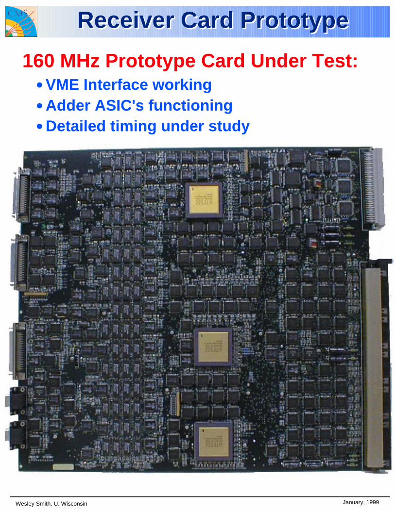
Receiver Card PrototypeReceiver Card Prototype
160 MHz Prototype Card Under Test:• VME Interface working• Adder ASIC's functioning• Detailed timing under study
Wesley Smith, U. Wisconsin January, 1999
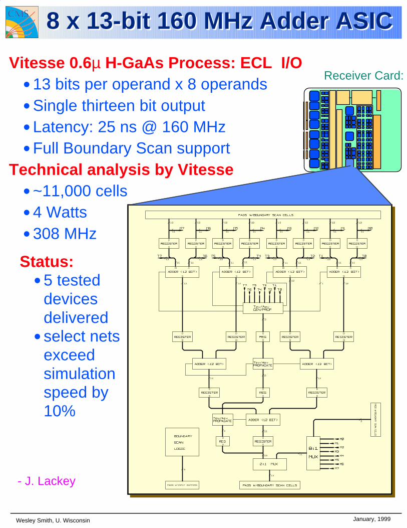
Vitesse 0.6µ H-GaAs Process: ECL I/O• 13 bits per operand x 8 operands• Single thirteen bit output• Latency: 25 ns @ 160 MHz• Full Boundary Scan support
Technical analysis by Vitesse• ~11,000 cells• 4 Watts• 308 MHz
Status:• 5 tested
devices delivered
• select nets exceed simulation speed by 10%
Receiver Card:
- J. Lackey
8 x 13-bit 160 MHz Adder ASIC8 x 13-bit 160 MHz Adder ASIC

Wesley Smith, U. Wisconsin January, 1999
160 MHz Backplane 160 MHz Backplane
std.2
conn. VMEarea
std.2
conn. VMEarea
triggerprocessing
area
triggerprocessing
area
singleVME
connector
singleVME
connector
- J. Lackey
Display 3 of 6 signal layers:
Receiver Cards
Electron Isolation Cards
Data Flow
Rear
3.56 cm center to centerPower Plane Dielectric
VME Section
Trigger DataSection
Not to scale: Traces
Top View:
Input clock to clock card:
0V
-1V0V
-1V
Last position on backplane*:
500 mV/div, 2 ns/div
Signal performance:rise < 1 ns:
Wesley Smith, U. Wisconsin January, 1999
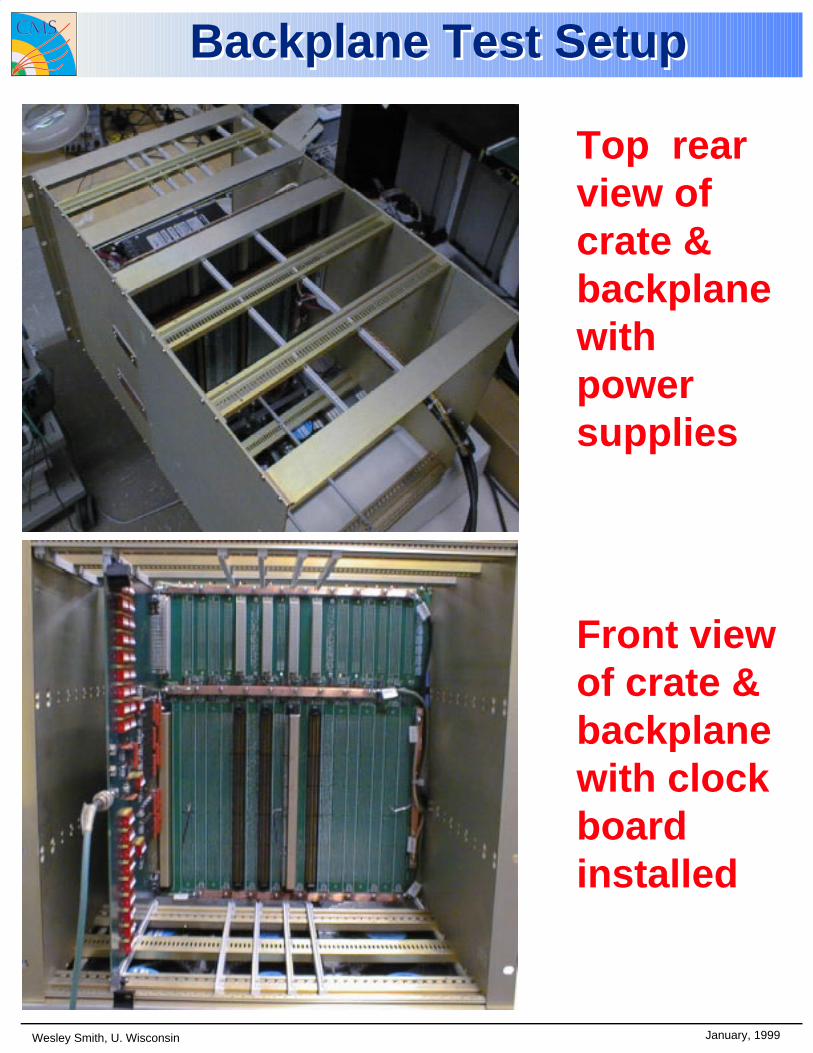
Backplane Test SetupBackplane Test Setup
Front view of crate & backplane with clock board installed
Top rear view of crate & backplane with power supplies
Janu
ary,
199
9W
esle
y S
mith
, U. W
isco
nsin
Ele
ctro
n
Iso
lati
on
Dif
fere
nti
al R
ecei
vers
& S
tag
ing
Ele
ctro
n ID
& J
et/S
um
mar
y C
ard
sE
lect
ron
ID &
Jet
/Su
mm
ary
Car
ds
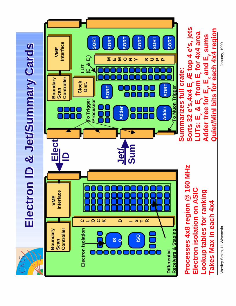
Su
mm
ariz
es f
ull
crat
e: S
ort
s 32
e's
,4x4
Et Æ
to
p 4
e's
, jet
s L
UT
s: E
x & E
y fro
m E
t fo
r 4x
4 ar
ea A
dd
er t
ree
for
Et,
Ex a
nd
Ey s
um
s Q
uie
t/M
inI b
its
for
each
4x4
reg
ion
Ele
ctID Je
t/S
um
Pro
cess
es 4
x8 r
egio
n @
160
MH
zE
lect
ron
iso
lati
on
on
AS
ICL
oo
kup
tab
les
for
ran
kin
gT
akes
Max
in e
ach
4x4 V
ME
Inte
rfac
e
C L O C K D I S T R
ISO
IS O
Bo
un
dar
yS
can
Co
ntr
olle
r
Ele
ctro
n Is
ola
tio
n
Dif
fere
nti
al
Rec
eive
rs &
Sta
gin
g
LU
T(E
x &
Ey)
To
Tri
gg
erP
roce
sso
r
V
ME
Inte
rfac
e
Bo
un
dar
yS
can
Co
ntr
olle
r
M E M O R Y S U P P
Ad
der
Ad
der
SO
RT
Clo
ckD
ist.
SO
RT
SO
RT
SO
RT
SO
RT
SO
RT
SO
RT
SO
RT
To
Mu
on
Tri
gg
er

E
Jet-Summary Card
t,Ey x,E
(18)
e/
●●
●
Jet
un-is
o-e/
γ
iso-
γ
Glo
bal C
AL
Trig
ger
Cra
te
tE
Glo
bal K
alor
imet
er T
rigge
r B
lock
diag
ram
m
E
Ale
xand
er M
ass,
Uni
vers
ity o
f Bris
tol
12.1
1.98
18-L
inks
each
19-L
inks
each
Lum
inos
ityDA
Q
Glo
bal S
umM
odul
et
4 hi
ghes
t Obj
ects
per
Link
4-Li
nks
Sor
t Pro
cess
or
Global Trigger Processor

Syn
c
Syn
c
Syn
cS
ync
Syn
c
Syn
c
Sor
t
Mod
ule
Fin
alF
ED
Sor
tA
SIC
Inpu
t
Mod
ule
Sor
t6
Link
sea
ch1
Link
each
Glo
bal
Trig
ger
Rea
dout
of a
ll in
put d
ata
Inte
rfac
e to
mis
erD
eran
do-
.OR
.
Late
ncy
Buf
fer
4040 40
10@16
0 M
Hz
Link
s
● ● ●13
1552 52 52
Glo
bal T
rigge
r In
ter.
52 b
it Li
nk-D
river
- In
put S
ort t
o F
inal
Sor
t
- F
inal
Sor
t to
Glo
bal T
r.
- S
ort t
o F
ED
Rea
r R
ecei
ver
Boa
rd
Sor
t-P
roce
ssor
Ale
xand
er M
ass,
Uni
vers
ity o
f Bris
tol
12.1
1.98
for
Inpu
t Sor
t Mod
ule
use
Mez
zani
ne C
ards
max
(3 o
ut o
f 9)
Com
pare
2
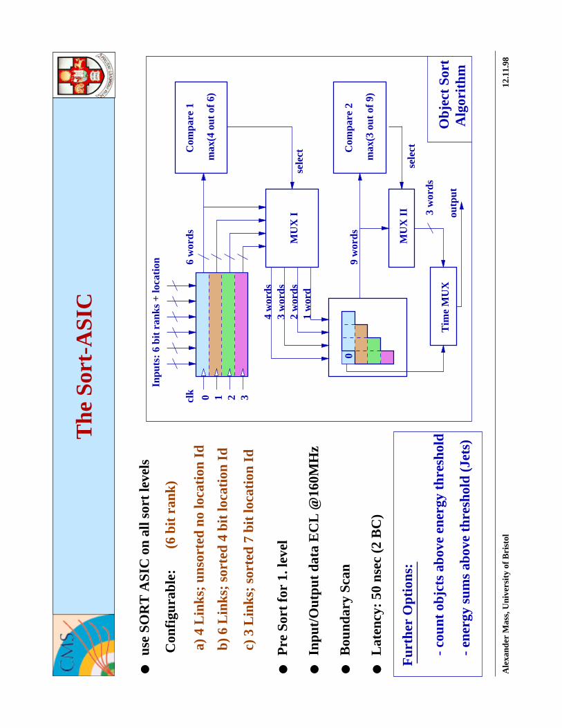
The
Sor
t-A
SIC
Ale
xand
er M
ass,
Uni
vers
ity o
f Bris
tol
12.1
1.98
9 w
ords
0
2 w
ords
1 w
ord
3 w
ords
4 w
ords
sele
ctM
UX
I
sele
ct
0 1 2 3clk
Tim
e M
UX
outp
ut
3 w
ords
MU
X II
Alg
orith
mO
bjec
t Sor
t
6 w
ords
Com
pare
1
max
(4 o
ut o
f 6)
Inpu
ts: 6
bit
rank
s +
loca
tion
Bou
ndar
y S
can
Inpu
t/Out
put d
ata
EC
L @
160M
Hz
use
SO
RT
AS
IC o
n al
l sor
t lev
els
● ● ● ● ●
Con
figur
able
:(6
bit
rank
)
Pre
Sor
t for
1. l
evel
Late
ncy:
50
nsec
(2
BC
)
b) 6
Lin
ks; s
orte
d 4
bit l
ocat
ion
Id
c) 3
Lin
ks; s
orte
d 7
bit l
ocat
ion
Id
a) 4
Lin
ks; u
nsor
ted
no lo
catio
n Id
Fur
ther
Opt
ions
:
- en
ergy
sum
s ab
ove
thre
shol
d (J
ets)
- co
unt o
bjct
s ab
ove
ener
gy th
resh
old

+ (
160M
Hz
-> 4
0MH
z) D
eMU
X +
160
MH
z cl
k ge
nera
tor
(R
AL)
- 64
bit
EC
L D
ata
Rec
orde
r/S
ourc
e, R
eado
ut v
ia c
usto
m fi
eldb
us (
Bris
tol)
160
MH
z S
ort A
SIC
Tes
t Sys
tem
- S
ort A
SIC
Tes
t Mod
ule:
4 r
ando
m p
atte
rn g
ener
ator
+ S
ort A
sic
●●
All
hard
war
e av
aila
ble,
Tes
t cur
rent
ly in
pro
gres
s
- O
bjec
t Sor
t for
(32
->
4)
- 4
Inpu
ts (
8 bi
t ran
k, 3
bit
loca
tion
Id)
@16
0MH
z
- E
CL
I/O (
Bou
ndar
y S
can)
- S
chem
atic
des
ign
- F
untio
n su
cces
sful
ly te
sted
@50
MH
z
Des
ign
of P
roto
type
Sor
t AS
IC (
man
ufac
ture
d 19
97)
Ale
xand
er M
ass,
Uni
vers
ity o
f Bris
tol
12.1
1.98
GC
T D
emon
stra
tor
Pro
ject
Task
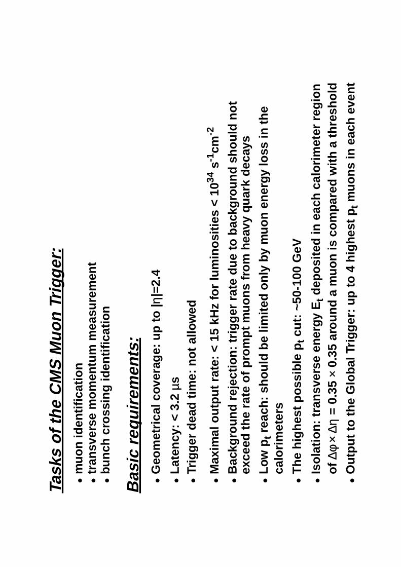
s of
the
CM
S M
uon
Trig
ger:
•m
uon
iden
tific
atio
n•
tran
sver
se m
omen
tum
mea
sure
men
t•
bunc
h cr
ossi
ng id
entif
icat
ion
Bas
ic re
quire
men
ts:
•G
eom
etric
al c
over
age:
up
to |
η|=2
.4
•La
tenc
y: <
3.2
µs
•Tr
igge
r de
ad ti
me:
not
allo
wed
•M
axim
al o
utpu
t rat
e: <
15
kHz
for
lum
inos
ities
< 1
034
s-1
cm-2
•B
ackg
roun
d re
ject
ion:
trig
ger
rate
due
to b
ackg
roun
d sh
ould
not
ex
ceed
the
rate
of p
rom
pt m
uons
from
hea
vy q
uark
dec
ays
•Lo
w p
t rea
ch: s
houl
d be
lim
ited
only
by
muo
n en
ergy
loss
in th
e ca
lorim
eter
s
•T
he h
ighe
st p
ossi
ble
pt c
ut: ~
50-1
00 G
eV
•Is
olat
ion:
tran
sver
se e
nerg
y E
t dep
osite
d in
eac
h ca
lorim
eter
reg
ion
of ∆
φ ×
∆η =
0.3
5 ×
0.35
aro
und
a m
uon
is c
ompa
red
with
a th
resh
old
•O
utpu
t to
the
Glo
bal T
rigge
r: u
p to
4 h
ighe
st p
t muo
ns in
eac
h ev
ent

Wesley Smith, U. Wisconsin January, 1999
η=0
4T
2T
MS1 MS2 MS3 MS4RPC pattern recognition- pattern catalog- fast logic
Muon trigger systemMuon trigger system
track segment
muon station 4muon station 3
muon station 2muon station 1
2 x extrapolation
threshold
3 track segment pairs arecombined to one track string f2 - f 1
DT and CSC track finding:- combines vectors- forms a track- assigns p
t value
The CMS muon trigger is based on:1) Dedicated trigger detector (Resistive Plate Chamber)2) Muon chambers (Drift Tubes, Cathode Strip Chambers)
pt = 6 GeV
pt = 3.5 GeV

0
100
200
300
400
500
600
700
800
020
040
060
080
010
0012
00Z
(cm
)
R (cm)R
PC
CS
CD
rift T
ubes
Wesley Smith, U. Wisconsin January, 1999
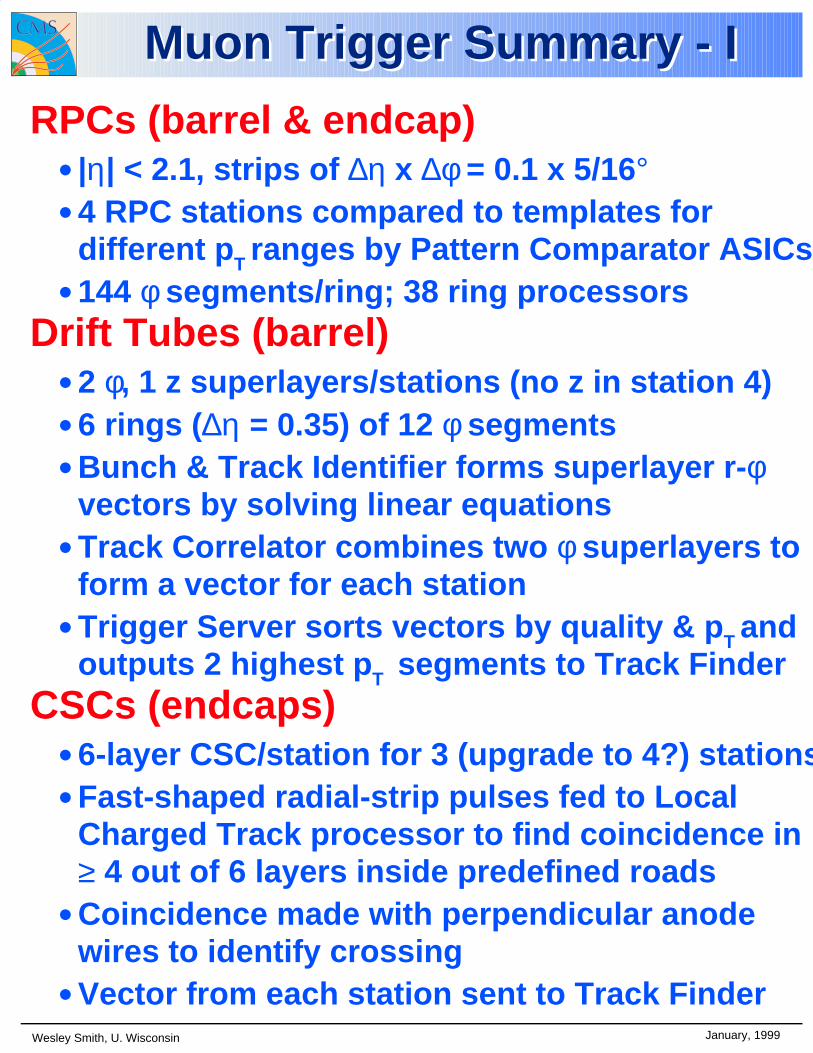
Muon Trigger Summary - IMuon Trigger Summary - I
RPCs (barrel & endcap)• |η| < 2.1, strips of ∆η x ∆φ = 0.1 x 5/16°• 4 RPC stations compared to templates for
different pT ranges by Pattern Comparator ASICs• 144 φ segments/ring; 38 ring processors
Drift Tubes (barrel)• 2 φ, 1 z superlayers/stations (no z in station 4)• 6 rings (∆η = 0.35) of 12 φ segments• Bunch & Track Identifier forms superlayer r-φ
vectors by solving linear equations• Track Correlator combines two φ superlayers to
form a vector for each station• Trigger Server sorts vectors by quality & pT and
outputs 2 highest pT segments to Track Finder CSCs (endcaps)
• 6-layer CSC/station for 3 (upgrade to 4?) stations• Fast-shaped radial-strip pulses fed to Local
Charged Track processor to find coincidence in ≥ 4 out of 6 layers inside predefined roads
• Coincidence made with perpendicular anode wires to identify crossing
• Vector from each station sent to Track Finder
Wesley Smith, U. Wisconsin January, 1999
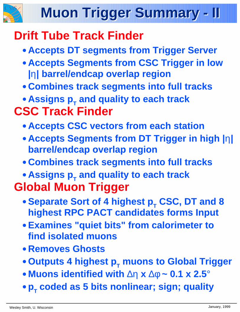
Muon Trigger Summary - IIMuon Trigger Summary - II
Drift Tube Track Finder• Accepts DT segments from Trigger Server• Accepts Segments from CSC Trigger in low
|η| barrel/endcap overlap region• Combines track segments into full tracks• Assigns pT and quality to each track
CSC Track Finder• Accepts CSC vectors from each station• Accepts Segments from DT Trigger in high |η|
barrel/endcap overlap region• Combines track segments into full tracks• Assigns pT and quality to each track
Global Muon Trigger• Separate Sort of 4 highest pT CSC, DT and 8
highest RPC PACT candidates forms Input• Examines "quiet bits" from calorimeter to
find isolated muons• Removes Ghosts• Outputs 4 highest pT muons to Global Trigger• Muons identified with ∆η x ∆φ ~ 0.1 x 2.5°• pT coded as 5 bits nonlinear; sign; quality
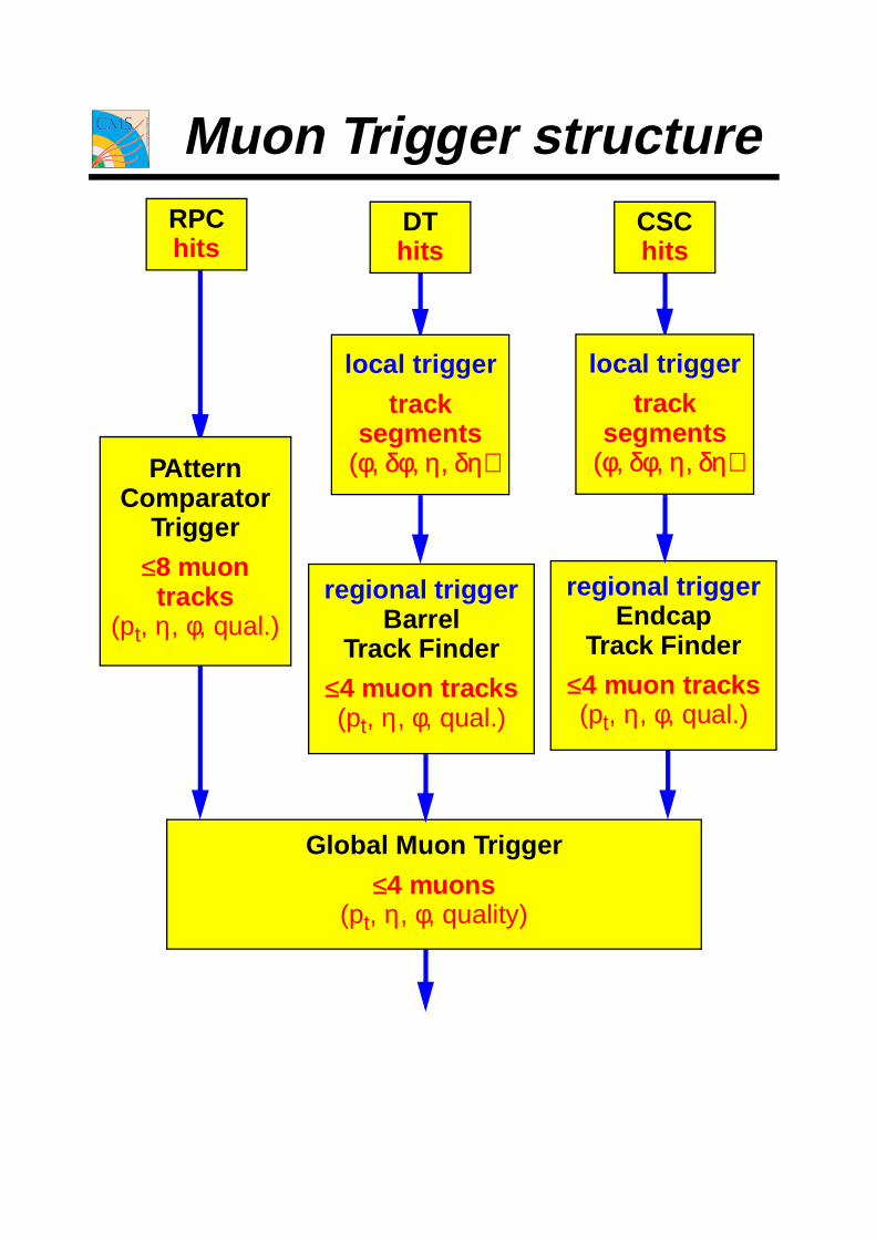
Muon Trigger structureRPChits
DThits
CSChits
PAtternComparator
Trigger
≤8 muontracks
(pt, η, φ, qual.)
local trigger
tracksegments
(φ, δφ, η, δη)
local trigger
tracksegments
(φ, δφ, η, δη)
regional triggerEndcap
Track Finder
≤4 muon tracks(pt, η, φ, qual.)
Global Muon Trigger
≤4 muons(pt, η, φ, quality)
regional triggerBarrel
Track Finder
≤4 muon tracks(pt, η, φ, qual.)

Track Finder
DT/CSC sorter
RPC
PACTprocessors
RPC ring sorter
RPC s/ring sorter
DT
BTI, TraCoTrig. Server
CSC
strip cardswire cards
motherboards
Global Trigger
Global Muon TriggerCALO quiet regions
CALO trigger
Port Cards
Bari
Warsaw
USADUBNA
BariWarsaw
Vienna
KoreaHelsinki
Padova, Bologna
Vienna
USABologna

RPC Pattern Comparator Trigger
Principle: pattern of hit strips is compared to predefined patterns corresponding to various p t.
MS 4
MS 3
MS 2
MS 1
LATCHES
LATCHES
pt
coding
4T
2T
MS4 MS3 MS2 MS1
RPC configuration in CMS

Interaction point
High Pt Muonpattern: (0,0,0)defined on 4 layerscode: (1,1,F)
Medium Pt Positive Muon pattern: (-4,4,4)defined on 3 layerscode: (0,0,A)
Segment i Segment i+1
code bit (5) - quality bit set to 1 if Muon defind on hits from 4 chamber;code bit (4) - Muon sign bit;code bits (3..0) - Muon Pt code
RPC Muon Station 4
Medium Pt Negative Muonpattern: (2,-1,-1)defined on 4 layerscode: (1,1,A)
RPC Muon Station 3
RPC Muon Station 1
RPC Muon Station 2 (reference)
Pattern Comparator (PAC) - idea
RPC Muon Trigger System
CMS Tridas Review, CERN November 9-13, 1998 Ignacy Maciek Kudla, Warsaw University
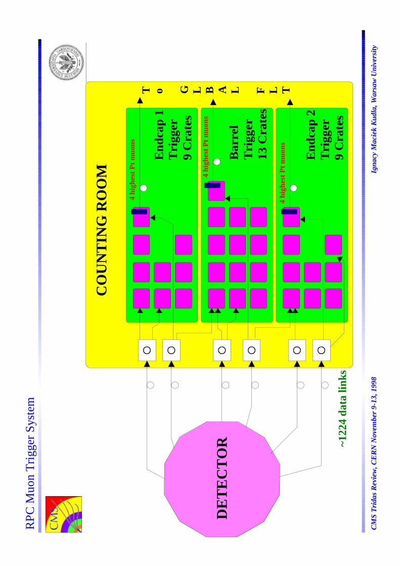
CO
UN
TIN
G R
OO
M
Bar
rel
Tri
gger
13 C
rate
s
End
cap
1T
rigg
er9
Cra
tes
End
cap
2T
rigg
er9
Cra
tes
DE
TE
CT
OR
4 hi
ghes
t Pt m
uons
4 hi
ghes
t Pt m
uons
4 hi
ghes
t Pt m
uons
T o G L B A L F L T
RPC
Muo
n Tr
igge
r Sys
tem
~122
4 da
ta li
nks
CM
S Tr
idas
Rev
iew
, CE
RN
Nov
embe
r 9-
13, 1
998
I
gnac
y M
acie
k K
udla
, War
saw
Uni
vers
ity

21
1211
310
49
58
67
RPC
Muo
n T
rigg
er C
rate
Int
erco
nnec
tions
PAC
Inpu
ts
Sort
ers
Gho
stB
uste
rs
Tri
gger
car
dsSo
rter
,C
ontr
ol,
Tim
ing
Car
d3
12
DA
Q c
ards
VM
EC
rate
Cnt
rl
12
34
56
78
910
1112
1314
1516
17
Tri
gger
Tow
ers
Rin
g Se
ctor
s
Tri
gger
car
ds
Tri
gger
Cra
te
CM
S Sy
nchr
oniz
atio
n W
orks
hop,
CE
RN
Nov
embe
r 11
, 199
8
Ign
acy
Mac
iek
Kud
la, W
arsa
w U
nive
rsity
RPC
Muo
n Tr
igge
r Sys
tem

PAC
Lin
k C
ard
GH
OST
BU
STE
R
PH
I
RX
VM
E
PAC
Hig
h P
t L
ow P
t
SOR
TE
R
.0 cm
.0 c
m
.0 cm
.0 c
mL
DE
MU
X
TQ
FP 1
44B
GA
225
BSC
AN
CT
RL
BS
BU
FF
ER
ME
MO
RY
PAC
PAC
PAC
PAC
PAC
PAC
PAC
PAC
PAC
PAC
PAC
PAC
PAC
PAC
PAC
PAC
PAC
PAC
PAC
PAC
PAC
PAC
PAC
PAC
PAC
PAC
PAC
PAC
PAC
PAC
PAC
PAC
PAC
PAC
PAC
PAC
PAC
PAC
PAC
PAC
PAC
PAC
PAC
PAC
PAC
PAC
PAC
PAC
PAC
PAC
PAC
PAC
PAC
PAC
PAC
PAC
PAC
PAC
PAC
PAC
LD
EM
UX
LD
EM
UX
LD
EM
UX
LD
EM
UX
LD
EM
UX
LD
EM
UX
LD
EM
UX
LD
EM
UX
LD
EM
UX
RX
RX
RX
RX
RX
RX
RX
RX
SOR
TE
R
SOR
TE
R
TR
IGG
ER
CH
EC
K
GH
OST
BU
STE
R
PH
I
TR
IGG
ER
CR
AT
E
CM
S Sy
nchr
oniz
atio
n W
orks
hop,
CE
RN
Nov
embe
r 11
, 199
8
Ign
acy
Mac
iek
Kud
la, W
arsa
w U
nive
rsity
RPC
Muo
n Tr
igge
r Sys
tem
Tri
gger
Boa
rd (b
arre
l)

RPC Muon Trigger System
CMS Tridas Review, CERN November 9-13, 1998 Ignacy Maciek Kudla, Warsaw University
40 dies (10 packed, 30 unpacked) delivered March 98
All building blocks of every packed PAC tested.The results are following:
- PAC programming (via JTAG - 10 MHz clock): - 8 PAC's - OK; - 1 PAC - 1 pattern bank not accesible; - 1 PAC - intermittent error.
- cascade, mask circuit: - 10 PAC's - OK;- encoding circuit: - 10 PAC's - OK;- code selection circuit (demuxes): - 10 PAC's - OK;- pattern selection circuit (muxes): - fast test - logically OK but timing problem found at level of input buffer and dynamic logic: - 3/4 tracks are working from 30 ns clock, - 4/4 track code are extended to 2 bx's.
PAC test results :

SORTER &MERGER
MERGERMERGER
SORTER &MERGER
SORTER &MERGER
MERGER
SORTER &MERGER
VME CARD 2
VME CARD 1
VME CARD 3
VME CARD 4
SORTER &MERGER
MERGERMERGER
SORTER &MERGER
SORTER &MERGER
MERGER
SORTER &MERGER
VME CARD 6
VME CARD 5
VME CARD 8
VME CARD 9
SORTER &MERGER
SORTER &MERGER
MERGER
SORTER &MERGER
VME CARD 11
VME CARD 10
VME CARD 12
VME CARD 13
SORTER &MERGER MERGER
MERGER
MERGER
VME CARD 7
MERGER
MERGER
Sorting tree in Ring Trigger Crate
6*(7+1)
4*(7+4)
4*(7+5)
4*(7+6)
4*(7+7)
4*(7+8)
In Ring Trigger Crate:- 12 Sorter&Mergers,- 12 Mergers.Total all 33 Ring Trigger Crates:- 792 Sorter or Mergers
TRIGGER CRATE
RPC Muon Trigger System
CMS Tridas Review, CERN November 9-13, 1998 Ignacy Maciek Kudla, Warsaw University
Wesley Smith, U. Wisconsin January, 1999
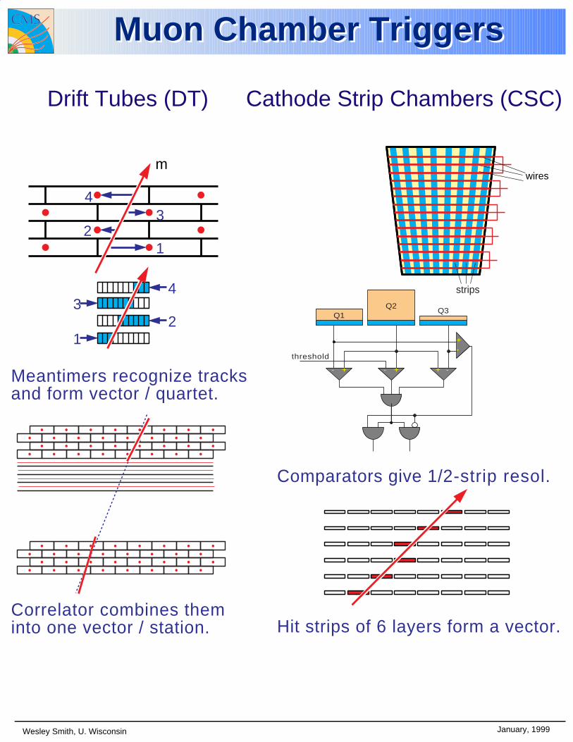
Muon Chamber TriggersMuon Chamber Triggers
strips
wires
Q2Q1
Q3
+-
+ -- +- +
threshold
CSC
Comparators give 1/2-strip resol.
Hit strips of 6 layers form a vector.
m
43
21
12
34
Drift Tubes
Meantimers recognize tracksand form vector / quartet.
Correlator combines theminto one vector / station.
(DT)Drift Tubes (DT) Cathode Strip Chambers (CSC)


Out 0 Out 1 Out 2 Out 3 Out 4 Out 5 Out 6 Out 7 Out 8 Out 9 Out 10 Out 11
In 0 In 1 In 2 In3
OuterLayer
InnerLayer
µ
Xcal
Kcal
D = 23.7 cm
Track Correlator
Correlates BTIs in the inner and outer SuperlayersRefines the track measurement Applies noise filtering using θ-view information
Track Correlator
µ
1
4
3
2 9
9
6
7
8
5
Bunch and Track Identifier
Bunch crossing is detected using a generalized mean-timer methodAt the same time the track inclination and position are measured
HTRG Alignment of four hitsLTRG Alignment of three hits
Triggers
LTRG triggers close to a HTRG are suppressed (LTS mechanism)
Bunch and Track Identifier

0
100
200
300
400
500
600
-5 -4 -3 -2 -1 0 1 2 3 4 5
0
10
20
30
40
50
60
-15 -10 -5 0 5 10 15
Position Difference [mm]
All Triggers
Position Difference [mm]
Low Quality
Position parameter quality
σ ~ 0.7 mm
σ ~ 1.15 mm
BTI # 6in the right time slot

Time slot
Time slot
HTRG
LTRG
Time distribution of BTI triggers

Fron
t-en
dFr
ont-
end
tran
sver
se v
iew
long
itudi
nal v
iew
... ......
TSϕ
TSθ
ΒΤΙ
s in
ner
SL
ΒΤΙ
s ou
ter
SLB
TIs
...T
DC
s...
TD
Cs
RO
S
RO
S m
aste
r
To
Muo
n R
egio
nal T
rigg
er
To
DA
Q
1 B
TI
/ 4 w
ires
1 T
RA
CO
/ 4
BT
Is
...T
RA
CO
s
1 B
TI
/ 4 w
ires
TR
Gθ
1 T
DC
/ 32
wir
es
From
oth
er c
ham
bers
of th
e sa
me
sect
or
1 T
SS /
4 T
RA
CO
s
...T
SSs
TSM
Ove
rvie
w o
f th
e el
ectr
onic
s la
yout
of
a ch
ambe
r
BT
I50
000
TR
AC
O 4
400
TSS
110
0T
SM
240
Tri
gger
ASI
CS{
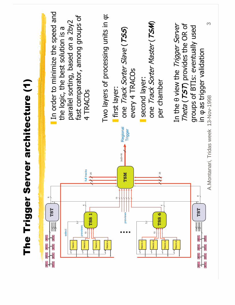
A.M
onta
nari,
Trid
as w
eek
13-
Nov
-199
83
7KH�7
ULJJHU�6HUY
HU�DUF
KLWHFWX
UH����
7ZR�OD\H
UV�RI�SURF
HVVLQJ
�XQLWV�LQ
�φ�
❚�ILUVW�OD
\HU�
��RQ
H�7UDFN�6R
UWHU�6ODYH
��76
6�
��HY
HU\���75
$&2V�
❚�VHFR
QG�OD
\HU��
��RQ
H�7UDFN�6R
UWHU�0
DVWHU��7
60�
��SH
U�FK
DPEH
U
,Q�WKH
�θ�YLHZ�WKH
�7ULJ
JHU�6H
UYHU
7KHWD��7
67��SURY
LGHV�WKH
�25�RI
JURX
SV�RI�%7
,V��HY
HQWXDOO\�XVHG�
LQ�φ�DV�WULJJH
U�YD
OLGDWLRQ
❚�,Q�RUGHU�WR�PLQLP
L]H�WKH�VS
HHG�DQ
G���WKH�ORJLF��WKH
�EHVW�VROXWLR
Q�LV�D�
��SD
UDOOHO�VRUWLQ
J��EDVHG
�RQ�D��E
\��
��IDVW�FRP
SDUDWRU��DPRQ
J�JURX
SV�RI�
����75
$&2V�

A.M
onta
nari,
Trid
as w
eek
12-
Nov
-199
84
)XOO�SHUIRUP
DQFH�$
6,&
�SUR
WRW\
SH�RI�766
❚�7H
VW�SHUIRUP
HG�Z
LWK�SURJUDP
PDE
OH�GHY
LFHV��;LOLQ
;��$OWH
UD��4XLFN/R
JLF���
���UHY
HDOHG�WKH�QH
HG�RI�XV
LQJ�$6
,&�WR�ILW�WKH
�VSH
HG�UHT
XLUHPHQ
W�
❚���
�$6,&�SURWRW\S
HV�Z
HUH�UHDG
\�DW�WKH
��EH
JLQQ
LQJ�RI�WKLV�\H
DU�
����&0
26�����
µP��(6
��WKURXJ
K�(X
UR3UDFWLF
H�������
�PP��6LOLFR
Q�DUHD
������
��,�2�SDG
V
����-7
$*�DQG
�EDFNX
S�SD
UDOOHO�LQWHUIDFH
����IXOO�SURJ
UDPPDE
LOLW\�RI�VRUWLQJ

A.M
onta
nari,
Trid
as w
eek
12-
Nov
-199
87
6LP
XODWLRQ�RI�WK
H�7
ULJJHU�6HUY
HU
❚�7K
H�76
�DOJRULWK
P�KDV�EHH
Q�WHVWHG
�LQ�WKH
�IUDPH�RI�WKH
�VLP
XODWLRQ�RI�&06
❚�7K
H�LGHD
O�DOJRULWK
P�VKR
XOG�ILQ
G��������RQO\�RQ
H�WUDFN�VHJP
HQW�LQ�VLQJOH�PXR
Q�HY
HQWV
��������UHMHFW�JKR
VWV�SURG
XFHG
�E\�QH
DUE\
�75$&
2V�
�������WZR�FR
UUHFW�VHJP
HQW�LQ�WZR�PXR
Q�HY
HQWV
��������KLJK
�HIILFLHQF
\�DQ
G�SX
ULW\�RQ
�VHFRQ
G�VHJP
HQW�
❚�6LPXODWLRQ�ZLWK
�RQH
�RU�WZ
R��PXR
QV�RI���
��*H9
�JLYHV
��SR
VLWLY
H�UHVXOWV
(IILFLHQF\�IRU��QG�WUDFN
����
(IILFLHQF\�IRU��QG�WUDFN
LQ�RSHQ�SDLUV
����
3URE��RI�FR
UUHFW�LG�RI�ERWK�WUDFN
V����
3URE��RI�FR
UUHFW�LG�RI�ERWK�WUDFN
VLQ�RSHQ�SDLUV
����
3URE��RI�JHQHUDWLQJ�D�IDNH��
QG
WUDFN
�LQ�RQH�P
XRQ�HYHQWV�
�����
��2SHQ�SDLUV� �WZR�PXRQV�GLVWDQW�PRUH�WKDQ���75$&2
CM
S R
evie
w 1
3 N
ovem
ber
1998
Jan
os E
rö/H
EP
HY
-Vie
nna
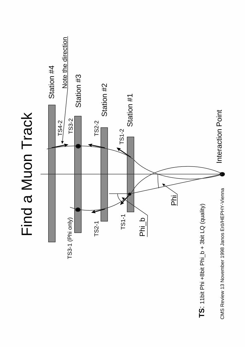
Fin
d a
Muo
n T
rack
Inte
ract
ion
Poi
nt
Sta
tion
#1Sta
tion
#4
Sta
tion
#3
Sta
tion
#2
TS
1-1
TS
1-2
TS
2-1
TS
3-1
(Phi
onl
y)
TS
2-2
TS
3-2
TS
4-2
Phi
Phi
_b
TS
: 11b
it P
hi +
8bit
Phi
_b +
3bi
t LQ
(qu
ality
)
Not
e th
e di
rect
ion

CM
S R
evie
w 1
3 N
ovem
ber
1998
Jan
os E
rö/H
EP
HY
-Vie
nna
Tra
ck F
inde
r P
roce
ssor
Fun
ctio
nal B
lock
s
Inpu
t R
ecei
ver
Uni
t
Ext
rapo
lato
rU
nit
Tra
ck
Ass
embl
ing
Uni
t
Par
amet
erA
ssig
nmen
tU
nit
8TS
Dat
a Inpu
ts fr
om
Nei
ghbo
urs
Out
puts
to
Nei
ghbo
urs
Inpu
ts fr
om
Nei
ghbo
urs
21 A
ddre
sses
max
. 8 A
ddre
sses
TS
Dat
a
2 T
rack
sw
. Par
amet
ers

CM
S R
evie
w 1
3 N
ovem
ber
1998
Jan
os E
rö/H
EP
HY
-Vie
nna
Cra
te w
ith S
ecto
r R
ecei
vers
Con
trol
ler
Pro
cess
or
Sec
tor
Rec
eive
r
Wed
geS
orte
r
Wesley Smith, U. Wisconsin January, 1999
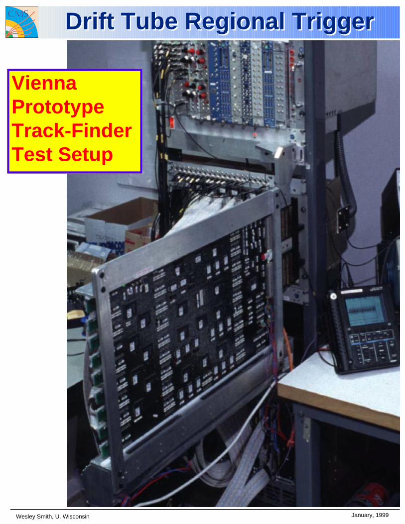
ViennaPrototypeTrack-FinderTest Setup
Drift Tube Regional TriggerDrift Tube Regional Trigger
D. A
cost
a, U
niv.
of F
lorid
aTr
iDA
S R
evie
w, N
ov. 1
998
5
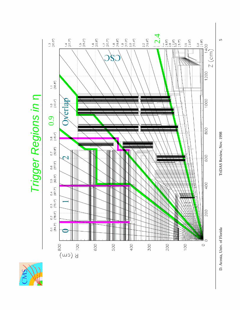
Trig
ger
Reg
ions
in η
0.9
2.4

D. A
cost
a, U
niv.
of F
lorid
aTr
iDA
S R
evie
w, N
ov. 1
998
2
CS
C M
uon
Trig
ger
Sch
eme
Str
ip F
E c
ards
Wire
FE
car
ds
Mot
herb
oard
TM
B
Por
t Car
d
PC
Sec
tor
Rec
eive
rS
ecto
r P
roce
ssor
OP
TIC
AL
SR
SP
CS
C T
rack
-Fin
der
CS
C M
uon
Sor
ter
Glo
bal µ
Trig
ger
DT
RP
C
FE
FE
Glo
bal L
1
2µ /
cha
mbe
r3µ
/ p
ort c
ard
3µ /
sec
tor
4µ
4µ
4µ
4µ
LCT
LCT
Str
ip L
CT
car
d
Wire
LC
T c
ard
On
cham
ber
In c
ham
ber
crat
e
In c
ount
ing
hous
e

Jay Hauser, UCLA TRIDAS Week, November 1998 11
Type Board SlotsCLCT 9 9ALCT 9 18MBT 5 5MBD 5 5MPC 1 1Total 29 38Fits two 9U crates
Trigger Crates
Each iron disk handles 12 sectors30o sectors on YE1 for ME1,60o sectors on YE2 for ME2 and ME3
Per sector:
Positions of 24 crates around the iron disks is under discussion.
Jay Hauser, UCLA TRIDAS Week, November 1998 5
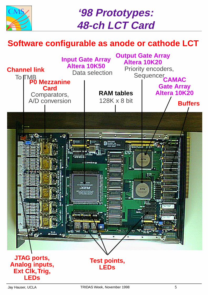
‘98 Prototypes:48-ch LCT Card
Channel linkTo TMB
Input Gate Array Altera 10K50
Data selection
RAM tables128K x 8 bit
P0 Mezzanine Card
Comparators, A/D conversion
Output Gate ArrayAltera 10K20Priority encoders,
Sequencer
Buffers
Test points, LEDs
JTAG ports,Analog inputs,Ext Clk, Trig,
LEDs
CAMACGate Array
Altera 10K20
Software configurable as anode or cathode LCT

Jay Hauser, UCLA TRIDAS Week, November 1998 11
Comparator Study #2
Fit track in Layers 1,2,4,5,6, look at comparator bits in Layer 3.
•
Simple tracking results are good•No corrections for gain, xtalk, etc.→Energy-weighted means →Corrected means by sin(x) gives ~300um resolution
→

Jay Hauser, UCLA TRIDAS Week, November 1998 18
Anode BX Efficiency Summary
Run 183 at H2old gas, HV=3.9kV, θ=25o, φ=0o, µ+(225), 4x4cm triganode thresholds 15~58fC
Coincidence Level
Relative Timing
BX Efficiency
1 0ns 98.0 ±1.0%
2 +3ns 99.2 ±0.3%
3 +8ns 99.2 ±0.3%
4 +12ns 99.1 ±0.5%
5 +14ns 98.5 ±0.6%
6 +19ns 98.0 ±0.8%

Wesley Smith, U. Wisconsin January, 1999
CSC Trigger LayoutCSC Trigger LayoutTrigger Mother Boards in Iron Disk Peripheral Crates: US & Dubna EMU
Peripheral Crates:Rice
Backplane
Optical Links:Rice
Counting RoomCrates: UCLA
Counting RoomCrates: UCLA
Counting RoomCrates: Florida
6 Sector ProcessorCrates
10° 10° 10° 10° 10° 10°
20° 20° 20°
10° 10° 10° 10° 10° 10°
20° 20° 20°
10° 10° 10° 10° 10° 10°
10° 10° 10° 10° 10° 10°
10° 10° 10° 10° 10° 10°
ME1/3
10° 10°10°10° 10°10°
ME1/1
ME1/2
ME1/A
ME2/2
ME2/1
ME3/2
ME3/1
ME1 Left ME1 Right
MuonPortCard
MuonPortCard
MuonPortCard
MuonPortCard
20°Sector
20°Sector 60° Sector 60° Sector
SectorReceiver
SectorReceiver
CSCSector
Processor
OVRSector
Processor
20°Sector
ME1 Center
18µ
MuonPortCard
16µ16µ 16µ 18µ
2µ2µ2µ 3µ3µ
6µ 6µ
Barrel
Barrel Barrel
D. A
cost
a, U
niv.
of F
lorid
aTr
iDA
S R
evie
w, N
ov. 1
998
10
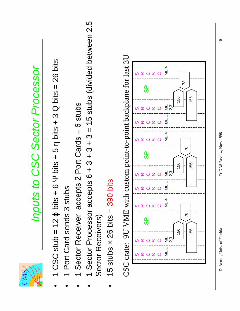
Inpu
ts to
CS
C S
ecto
r P
roce
ssor
•1
CS
C s
tub
= 1
2 ϕ
bits
+ 6
Ψ b
its +
5 η
bits
+ 3
Q b
its =
26
bits
•1
Por
t Car
d se
nds
3 st
ubs
•1
Sec
tor
Rec
eive
r a
ccep
ts 2
Por
t Car
ds =
6 s
tubs
•1
Sec
tor
Pro
cess
or a
ccep
ts 6
+ 3
+ 3
+ 3
= 1
5 st
ubs
(div
ided
bet
wee
n 2.
5S
ecto
r R
ecei
vers
)
•15
stu
bs ×
26
bits
= 3
90 b
its
CSC
cra
te:
9U V
ME
with
cus
tom
poi
nt-to
-poi
nt b
ackp
lane
for l
ast 3
US R C S C
SP
S R C S C
S R C S CM
E 1
ME
2,3
ME
4
156
156
78
S R C S C
SP
S R C S C
S R C S CM
E 1
ME
2,3
ME
4
156
156
78
S R C S C
SP
S R C S C
S R C S CM
E 1
ME
2,3
ME
4
156
156
78

D. A
cost
a, U
niv.
of F
lorid
aT
riDA
S R
evi
ew
, Nov
. 199
815
Sec
tor
Pro
cess
or B
lock
Dia
gram
�������������
�������������
43x
21
��
EU
3 -
4
N
OV
EM
BE
R, 2
nd.
EU
2 -
4 E
U 2
- 3
33x
21
43x
21
23x
21
33x
21
23x
21
QSU
5(
3 -
4 )
( 2
- 4
)Q
SU 4
QSU
3(
2 -
3 )
VME BUS
INTERFACEREADOUT
DOWNLOADING/
CONNECTOROUTPUT
Pt
LO
OK
-UP
MU
X
33x
21
1**
3x21
EU
1**
- 3
EU
1*
- 3
33x
213x
211*
EU
1**
- 2
23x
21
1**
3x21
EU
1*
- 2
23x
213x
211*
QSU
2(
1 -
3 )
QSU
1
( 1
- 2
)
3 - 4
2 - 4
2 - 3
1 - 3
FSU
TA
U 1
(1-2
-3,
1-2
-4,
1-3
-4,
2-3
-4 ) 2-3-4
1-3-4
1-2-3
1-2-4
3 - 4
2 - 4
2 - 3
1 - 3
1 - 2
CL
OC
KE
D
TA
U 2
( 1-
2-3-
4 )
F
IFO
FIG
.1.
TR
AC
K F
IND
ING
PR
OC
ESS
OR
. BL
OC
K D
IAG
RA
M.
TT
A
QT
A
CONTROLINTERFACE
BACKPLANECUSTOM
9U
INPUT DATA &
1 - 2D
ata
Con
trol
Out
put
Dat
a
3x2
2 =
66
Input Data
LID
STA
15x1
3x21
DT
A
9x21*- 2
9x21** - 2
9x21* - 3
9x22 - 3
9x22 - 4
9x2
1** - 39x2
3 - 4
- C
ontr
ol L
ine
- D
ownl
oadi
ng/
R
eado
ut L
ine
- D
ata
Lin
e
15x26=390
EU
- E
xtra
pola
tion
Uni
tQ
SU -
Qua
lity
Sele
ctio
n U
nit
TA
U -
Tra
ck A
ssem
blin
g U
nit
FSU
- F
inal
Sel
ecti
on U
nit
Ass
embl
age
TT
A -
Tri
pple
Tra
ckD
TA
- D
oubl
e T
rack
A
ssem
blag
eQ
TA
- Q
uadr
uple
Tra
ck
A
ssem
blag
e
LID
- L
ook-
Up
Inpu
t D
ata
STA
- S
elec
ted
Tra
ck A
ddre
ss
3x7
3x7
3x7
3x7
3x7
3x10
3x16
3x22
3x7
3x7
3x7
3x7
3x7
3x11
3x11
3x11
3x11
Ext
rapo
latio
n U
nits
Qua
lity
Sel
ectio
nU
nits
Tra
ck A
ssem
bler
Fin
al S
elec
tion
Uni
t
Ass
ignm
ent U
nit
and
Out
put
FIF
O
Inpu
t

GM
T:P
rese
ntD
esig
n
8S
YN
CF
IFO
s24
Tab
les
PQ
_i *
SR
K_j
µ R
PC
QU
IET
BIT
Sfr
om C
alor
imet
er
VM
E
VM
E a
ddr
Pre
proc
essi
ng
Syn
chro
nisa
tion
Cal
cula
te M
AT
CH
QU
ALI
TIE
S
VM
E a
ddr
1 bi
t x 8
MUX
4
tabl
e
8
SU
B
SU
B
tabl
e
MUX
ij∆ϕ
DA
TA
pip
elin
e
4 µ
RP
C4
µ D
T/C
SC
SE
LEC
T M
AT
RIX
SE
L_ij
= 1
...ta
ke R
PC
=
0 ..
.take
DT
/CS
C
8
PA
IR_i
j
(if S
RK
_i =
SR
K_j
->
take
RP
C)
SE
L_ij
Com
pare
ran
ks o
f RP
C a
nd D
T/C
SC
muo
ns
1 bi
t x 1
6
8 bi
ts(?
) x
8
4
∆ϕ
+ ω
∗∆η2
2
∆η w*
+ 2∆ϕ
If M
Q_i
j is
bette
r th
an a
ll ve
rtic
al a
nd h
oriz
onta
l nei
ghbo
urs,
then
it is
the
best
mat
ch fo
r2
muo
n ca
ndid
ates
4
256*
6 bi
ts
4
PA
IR L
OG
IC
Fin
d R
PC
- D
T/C
SC
Muo
nPai
rsus
ing
the
MA
TC
HQ
UA
LIT
Ys
of a
ll po
ssib
le c
ombi
natio
ns
4x4
mat
rix
MQ
_ij
P
AIR
QU
ALI
TY
ass
ignm
ent
= P
Q_i
= 1
for
sing
le m
uons
= 0
for
loos
ing
mem
ber
of p
air
= M
Qxx
for
win
ning
mem
ber
of p
air
PQ
_DT
1.
..4P
Q_R
PC
1...
4
RA
NK
TA
BLE
Sfo
r 8
muo
ns
8 --
> 4
SO
RT
ER
RK
_i =
Sin
gle
Ran
k of
8 m
uon
cand
idat
es (
SR
K_i
)re
duce
d re
solu
tion
for
η ϕ
pt a
nd Q
8 sy
ncS
RA
M c
hips
SIN
GLE
-RA
NK
TAB
LES
for a
ll 8
muo
n ca
ndid
ates
Cal
cula
te if
a m
uon
poin
ts to
an a
ctiv
e Q
UIE
T b
it
appe
nd
QU
IET
_i
8 m
uon
cand
idat
es
MQ
_ij
if E
MP
TY
_ij =
1 th
enlo
w M
Q_i
j
p t
MQ
_ij
4x4
mat
rix
8 bi
ts x
81
bit x
8
EM
PT
Y_i
j=
1 if
pt_
i=0
or p
t_j=
0
8 th
resh
old
com
para
tors
QU
IET
BIT
LO
GIC
VM
E
VM
E
VM
E a
ddr
VM
E a
ddr
VM
E
VM
EIn
tern
al V
ME
bus
to lo
ad lo
ok-u
pta
bles
ant
to s
py r
esul
ts
6 bi
ts x
16
Uni
t-C
onve
rter
s
MA
TC
HQ
UA
LIT
Y
Fin
d M
AT
CH
ING
MU
ON
S
geMUX
2
6 bi
ts x
8 VM
E
4 m
uons
GLO
BA
LT
RIG
GE
R
VM
E
µ D
T/C
SC
3T
able
sη
ϕ p t
3T
able
sη
ϕ p t
µµ
1 bi
t x 1
6
6 bi
ts x
16
SR
K_j
η ϕSR
K_i
18
ij∆η
4 µ
RP
C4
µ D
T/C
SC
k
SR
K_i
Nor
bert
Neu
mei
ster
,HE
PH
YV
ienn
aTr
igge
rR
evie
w,N
ov.
1998
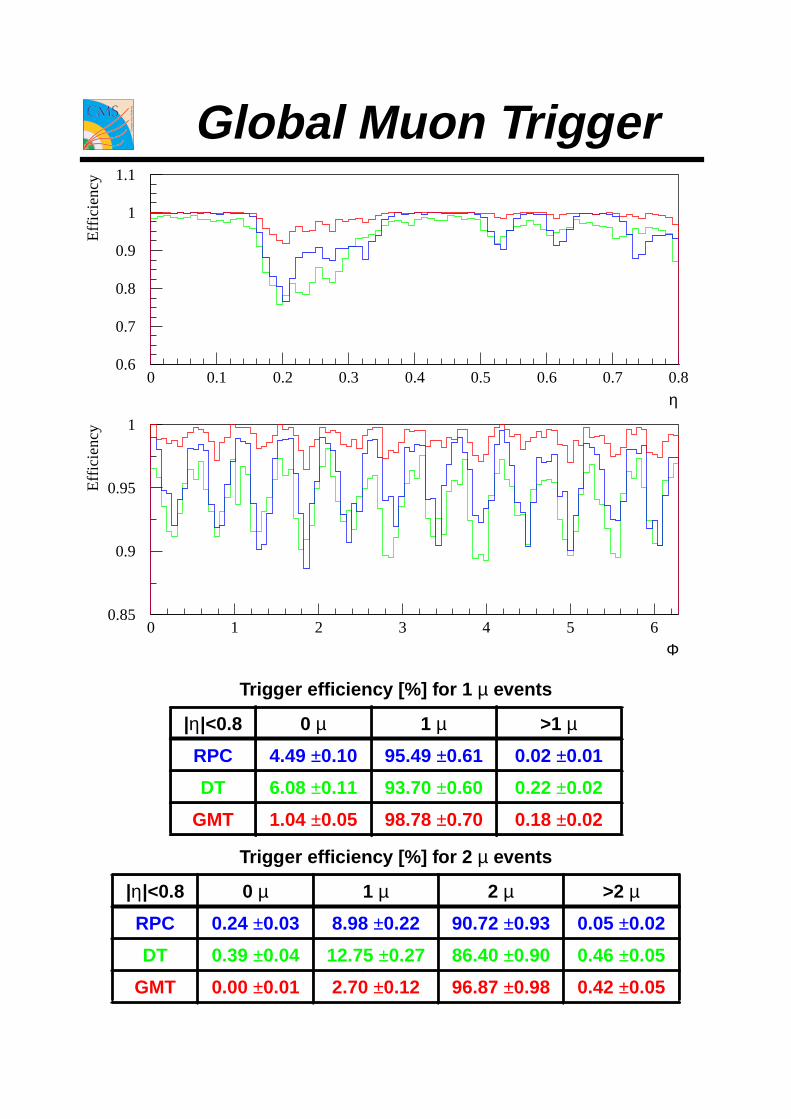
0.6
0.7
0.8
0.9
1
1.1
0 0.1 0.2 0.3 0.4 0.5 0.6 0.7 0.8
0.85
0.9
0.95
1
0 1 2 3 4 5 6
η
Effi
cien
cy
Φ
Effi
cien
cy
pT [GeV/c]
Effi
cien
cy
0.85
0.9
0.95
1
0 10 20 30 40 50 60 70 80 90 100
Trigger efficiency [%] for 1 µ events
|η|<0.8 0 µ 1 µ >1 µ
RPC 4.49 ±0.10 95.49 ±0.61 0.02 ±0.01
DT 6.08 ±0.11 93.70 ±0.60 0.22 ±0.02
GMT 1.04 ±0.05 98.78 ±0.70 0.18 ±0.02
Trigger efficiency [%] for 2 µ events
|η|<0.8 0 µ 1 µ 2 µ >2 µ
RPC 0.24 ±0.03 8.98 ±0.22 90.72 ±0.93 0.05 ±0.02
DT 0.39 ±0.04 12.75 ±0.27 86.40 ±0.90 0.46 ±0.05
GMT 0.00 ±0.01 2.70 ±0.12 96.87 ±0.98 0.42 ±0.05
Global Muon Trigger

LV2 input 100 kHz / safety factor 3 = LV1 output 15+15 kHz
LV2 input 75 kHz / safety factor 3 = LV1 output 12+12 kHz
threshold 2-4 GeV means the minimal possible muon p t cut~4 GeV in the barrel, ~2 GeV in the endcap
L = 1033cm-2s-1 L = 1034cm -2s-1
trigger threshold rate [kHz] threshold rate [kHz]type [GeV] indiv. cumul. [GeV] indiv. cumul.ΣEt 150 1.0 1.0 400 0.5 0.5
Etmiss 40 2.1 2.8 80 1.3 1.7
e 12 10.3 12.3 25 6.8 8.3e e 7 1.5 13.1 12 1.5 9.5
j 50 2.0 13.5 100 2.1 10.7j j 30 1.6 13.9 60 2.2 11.6j j j 20 1.0 14.1 30 3.2 13.3j j j j 15 0.7 14.2 20 3.0 14.3e j 9, 15 6.0 15.2 12, 50 1.4 14.9µ 7 7.0 7.0 20 7.8 7.8
µ µ 2-4 0.5 7.3 4 1.6 9.2µ e/γ 2-4, 7 2.4 9.2 4, 8 5.5 14.4µ eb 2-4, 4 5.2 12.8µ j 2-4, 10 4.2 14.4 4, 40 0.3 14.3
µ Etmiss 2-4, 40 0.2 14.4 4, 60 1.0 15.3
µ ΣEt 2-4, 100 0.7 14.4 4, 250 0.2 15.3
µ 7 7.0 7.0µ µ 2-4 0.5 7.3
µ e/γ 2-4, 7 2.4 9.2µ eb 2-4, 4.5 3.3 11.1µ j 2-4, 15 2.0 11.9
µ Etmiss 2-4, 40 0.2 11.9
µ ΣEt 2-4, 100 0.7 11.9
Muon and Calorimeter Trigger Rates
LV1 output rate is reduced to the required limit by adjusting the trigger thresholds
Wesley Smith, U. Wisconsin January, 1999
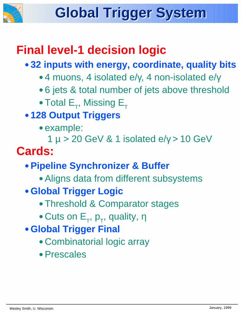
Global Trigger SystemGlobal Trigger System
Final level-1 decision logic• 32 inputs with energy, coordinate, quality bits
• 4 muons, 4 isolated e/γ, 4 non-isolated e/γ• 6 jets & total number of jets above threshold• Total ET, Missing ET
• 128 Output Triggers• example:
1 µ > 20 GeV & 1 isolated e/γ > 10 GeV
Cards:• Pipeline Synchronizer & Buffer
• Aligns data from different subsystems• Global Trigger Logic
• Threshold & Comparator stages• Cuts on ET, pT, quality, η
• Global Trigger Final• Combinatorial logic array• Prescales

GLOBAL TRIGGERCRATE
10.11.98 A.T. HEPHY VIENNA
144 ISOLATION BITS=9 Channels with 16 bits
MUONS:4 RPC4 DT
4 CSC
GLOBALMUONTRIGGER
4EG4IEG4HAD
6JETETT
ETM
TECHNICALTRIGGERS12 CHAN=
12.24=288bits
AMP-Z-PACK 2mm BACKPLANECONNECTORS 488 pins
GLOBAL TRIGGER
CHANNEL LINK for 28 bits5LVDS pairs =10lines
CUSTOM BACKPLANE: VME + fast links
TTC
CAPACITY of Backplane: 40 ChannelLinks+88 CTRL lines
12 FREECHAN.
PSB12PSB12
9CHISO-bits
GTMU GTMU PSB12 PSB12 PSB12 GTL GTL GTF GTL PSB12
3 free
TIM
36 (40)CH24 CH<40 xx bits
GTFE
CLK+CTRL
GTFE LINKto GTFE
8GTFE LINKS
1-2DAQLINKS
DAQ TTC
Send 4MUONS viabackplane or frontpanel
4MUONS
**
**
PSB12=12Ch.PipelineSynchronisingBufferGTL =GlobTrigg Logic moduleGTF =GlobTrigg Final moduleGTFE=GlobTrigg FrontEnd moduleTIM = Timing ModuleGTMU=Global Trigger for MUONS
optional 80MHzparallelSYP
orXIN
28bits->5 diffPar->Ser
DPmem
VME
CLK, BCResStart
JTAG
1 of 12 CHANNELsoptionalparallel
28 bits LVDS
PSB OVERVIEW
5diff->28 bitsSer->Par
X_DPMBC_nrEvent_nr
24.10.98 A.T. HEPHY VIENNA
CHANNELLINK
MIN. LATENCY: 3 bx PIPELINE DELAY5 bx FIFO DELAY
GTFELink
Readout processor
PIPELINE or FIFO DELAYSYNCHRONISATION by TTCrx40 MHz CLKBCRes....every LHC-cycleBC-counters
GTFEFrontEnd
Card
1 or 3 BX 1 BX1 BX
TIM
TIM

VME
TTC
GTL Logic module
29.10.98 A.T. HEPHY VIENNA
PSB
FPGA
GTL-ovw.cdd
OR- LOGIC
CLK40CLK80
BCntRes
4 CHANNLINKS
PSB 4 CHANNLINKS
SETUPREGS
ALGO chip64 algorithms
PSB 4 CHANNLINKS
36 (40) CHANNELS=9(10) groups
128ALGORITHMS
128 CABLEDRIVERS
LATENCY 4 BX
OR CHIP:(3840+128)=3968 IO pins3968/12= 331 IO-pins
-->12 OR chips
24x4=96 signals
768x10=7680 bits--> 3840 nets
128 algo bits
96x10=960 input bits
80MHz transfer between ALGO and OR chips: bits/2=nr.of nets
ALGO CHIP: logic for 64 algorithms6 bits x 64 algor.=384bits384/2= 192 OUT-pins (80MHz)96 IN-pins(40MHz) ---> 288 IO-pins
-->20 ALGO chips
40MHz
80MHz
40MHz
ALGO chip64 algorithms
ALGO chip64 algorithms
1BX 1BX1BX 0.5BX 0.5BX
GTF
VME
ALGO chip forCalorimeter
Particles2.11.98
HEPHY VIENNA
PSB
FPGA
GTL-Algo_Calo.cdd
4 PARTICLES
SETUPREGS
LATENCY 3 BX
24x4=96 INPUTS at 40 MHz
80MHz transfer between ALGO and OR chips: bits/2=nr.of nets
COMP.MATRIX
1BX 1BX1BX
OR-chip
16 WindowComparatorsin ETA, PHI
TH(J)
ET(I) of4
Particles
ET(I,J)
FIND A-particlesFIND B-particles...........FIND F-particles
VME
LOGIC to FIND A-particles
Calculate 6 different numbersof calorimeter particles
6 bits
LOGIC for 1 CALO-ALGORITHM
64 CALO-ALGORITHMS
6bits x 64 algo. = 384 bits384/2=192 OUTPUTS at 80 MHz
N.(N+1)/2=10 COMP

GTF Final Logic module4.11.98 A.T HEPHY VIENNA
GTF-ovw.cdd
128ALGORITHM
BITS
GTLTTC
CLK40CLK80
BCntRes
JTAG
READOUT X_DPM
BC-numberEventnr
GTFEFrontEnd Card
128Pre-
scalers
FinalOR
logic
DPMTIM
DPM
DPM=Dual Port Memory
L1_ACCEPT
VMEReadout processor
GTFELink
setup by VME
Local Monitoring + Tests
CableDrivers
Events + Global Monitoring
Rec
eive
r +
reg
iste
r
MonitoringCOUNTERS
A.Taurok 2.11-98
Timing ModuleTIM
TIM-Ovw.cdd
TTCrx
FIFO32 bits
20 MHz
BCnrBCnr
GT-Backplane
Eventnr
Local 40MHz ClockClockChip
40 MHz Clock
80+20 MHz Clock
40 MHz
Eventnr*
Bus to allPSB+GTFmodules
Point2pointto all
modulesBCntRes
40 MHz Clock
LocalBC_Cntr
LocalEvent_Cntr
NewRun
L1Acc
SimL1Acc
X_DPM extracts data from DPM on GTF + all PSB boards.L1Acc extracts EVENT data.SimL1Acc simulates L1Acc.Read_Mon_Bx reads DPM data for Global Monitoring.
X_DPM
BCntRes
3to1MUX
X_DPM
*)Eventnr. with Mon/Event flag
L1Acc
2to1MUX
Mon BCnrLocal BCnr
VME
Global MonitoringRead_Mon_Bx
green=VME
SimL1Acc
TTC_ON
ClockFanout
BCntResFanout
TTC_onFanout

'
&
$
%
| CMS Synchronization Workshop, Nov 1998 |
Distribution of CLK and L1 to Front{End
TTCvi
DAQ
APVs
Underground counting room
FED FEC
FEM CCUM
TTCrx TTCrx
PLLPLL
Experimental hall
7)
5)
6)
4)
3)2)
1)
CLK + L1
L1LHC CLK
L1BX #
EV #CLK
B0
L1 delay along the critical path TTCvi ! FEM:
1) TTCvi (input) ! TTCrx (output): ' 135ns + 5ns/m (10 BX with
20m �bre)
2) TTCrx on FEC: programmable delay, foreseen to be set to zero
3) FEC, opto!electrical conversion: < 50ns ( < 2 BX)
4) FEC ! CCUMs: 90 to 120 m optical �bre ! 450 to 600 ns (18 to
24 BX)
5) Ring of CCUMs: ' 2m of electrical cables ! ' 20ns (< 1 BX)
6) CCUM: opto!electrical conversion + distribution via electrical cables
to the PLLs in the FE + (CLK+L1) decoding ! ' 75ns (3 BX) (?)
7) PLL on the FEM: programmable (�ne and coarse) delay
Impact on the latency
3
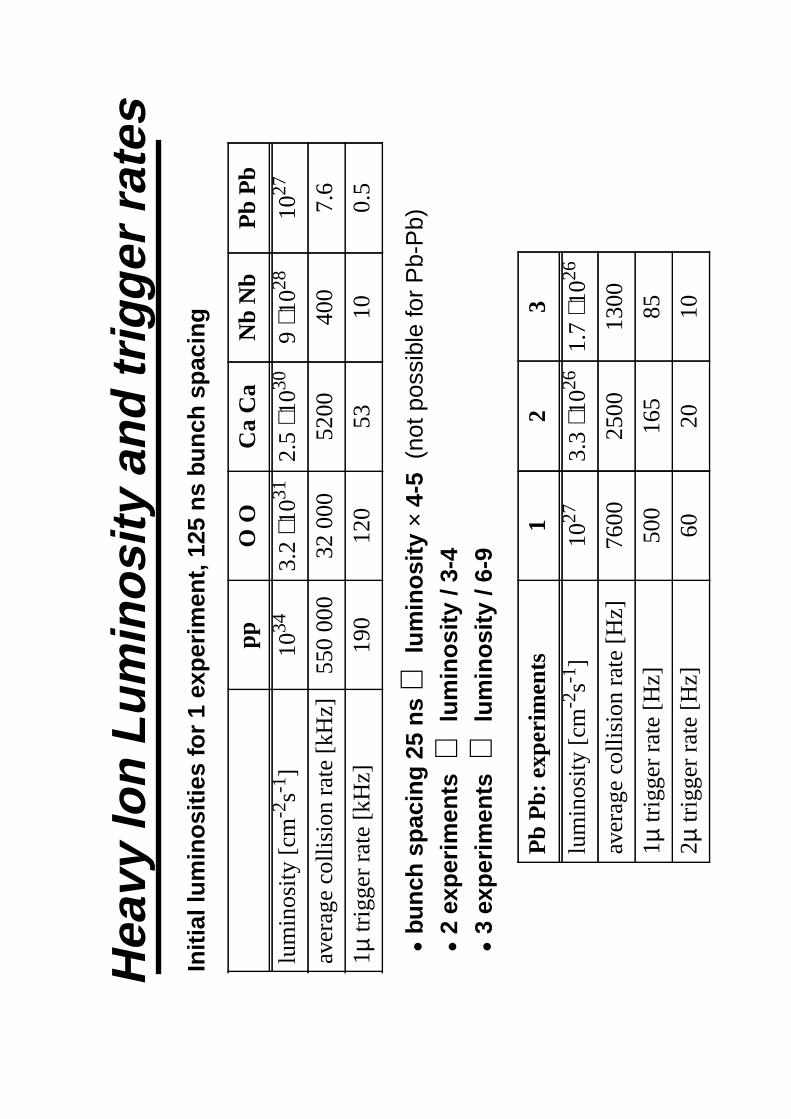
Initi
al lu
min
ositi
es
for
1 ex
perim
ent,
125
ns
bunc
h sp
acin
g
•bu
nch
spac
ing
25 n
s⇒
lum
inos
ity
× 4-
5(n
ot p
ossi
ble
for
Pb-
Pb)
•2
expe
rimen
ts
⇒ lu
min
osity
/ 3-
4•
3 ex
perim
ent
s⇒
lum
inos
ity /
6-9
pp
O O
C
a C
a N
b N
b P
b P
b
lum
inos
ity [c
m-2
s-1]
1034
3.2
⋅ 1031
2.5
⋅ 1030
9⋅ 1
02810
27
aver
age
colli
sion
rat
e [k
Hz]
550
000
32 0
00
5200
40
0 7.
6
1µ tr
igge
r ra
te [k
Hz]
190
120
53
10
0.5
Pb
Pb:
exp
erim
ents
1 2
3
lum
inos
ity [c
m-2
s-1]
1027
3.3
⋅ 1026
1.7
⋅ 1026
aver
age
colli
sion
rat
e [H
z] 76
00
2500
13
00
1µ tr
igge
r ra
te [H
z] 50
0 16
5 85
2µ tr
igge
r ra
te [H
z] 60
20
10
Hea
vy Io
n Lu
min
osity
and
trig
ger
rate
s
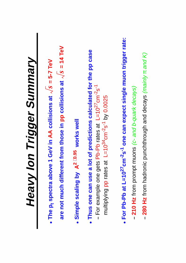
•T
he p
t spe
ctra
ab
ove
1 G
eV i
nA
A c
ollis
ions
at
=
5-7
TeV
are
not
muc
h di
ffere
nt f
rom
thos
e i
npp
col
lisio
ns a
t
= 1
4 Te
V
•S
impl
e sc
alin
g by
A2
⋅0.9
5 w
orks
wel
l
•T
hus
one
can
use
a lo
t of p
redi
ctio
ns c
alcu
late
d fo
r th
e pp
cas
e—
For
exa
mpl
e on
e ge
tsP
b-P
b ra
tes
atL=
1027
cm-2
s-1
mul
tiply
ing
pp r
ates
at
L=10
34cm
-2s-1
by
0.00
25
•F
or P
b-P
b at
L=1
027
cm-2
s-1 o
ne c
an e
xpec
t sin
gle
muo
n tr
igge
r ra
te:
—21
0 H
z fr
om p
rom
pt m
uons
(c-
and
b-qu
ark
deca
ys)
—28
0 H
z fr
om h
adro
nic
punc
hthr
ough
and
dec
ays
(mai
nly
π an
d K
)
s
s
Hea
vy Io
n T
rigge
r S
umm
ary

Ass
umpt
ions
—L=
1027
cm-2
s-1 (
1 ex
perim
ent r
unni
ng a
t the
tim
e) f
or P
b-P
b—
mas
s st
orag
e ca
paci
ty: ~
100
MB
/s—
equa
l rat
es fo
r m
uon
and
calo
rimet
er tr
igge
rs—
max
. eve
nt s
ize
(cen
tral
col
lisio
ns):
Trig
ger
stra
tegy
•R
equi
re s
ingl
e m
uon
trig
ger
(|
η|<
1.5)
at t
he fi
rst l
evel
⇒
500
Hz
•S
earc
h fo
r a
seco
nd m
uon
(|
η|<
1.5)
at t
he s
econ
d le
vel
⇒
60
Hz
•Li
ttle
or n
o re
duct
ion
need
ed a
t hig
her
leve
ls
Det
ecto
rO
ccup
ancy
k B
ytes
Pix
el b
arre
l<
0.5
%30
0
MS
GC
4 la
yers
+ 4
dis
ks~
10 %
826
EC
AL
full
(1 ti
me
slic
e)10
0 %
260
HC
AL
full
100
%28
Muo
n D
T+C
SC
+RP
C<
0.1
%54
TOTA
L~1
.5 M
B
Str
ateg
y fo
r dim
uon
trig
ger

Wesley Smith, U. Wisconsin January, 1999
CMS Trigger OrganizationCMS Trigger Organization
TriDASS. Cittolin
Trigger:W. Smith
DAQ:S. Cittolin
Calorimeter: W. Smith
Muon: G. Wrochna
Global: C. Wulz
Primitives:P. Busson
Regional: W. Smith
Global: G. Heath
Rd.& Ctrl: S. Silva
RPC: Krolikowski
CSC: J. Hauser
DT: P. Zotto
Trk Find:F. Szoncso
Global:A. Taurok
Processor
Monitoring

The Compact Muon Solenoid. SC 1998
Trigger cost book 9
103
CMS Cost Estimate - Version 9 Release Date: March 31, 1998
No. Item Unit Type # Units Unit Cost Total Cost
6.1.1 CALORIMETER TRIGGER 5225 0
6.1.1.1 Regional trigger System 1 4050.020 4050
6.1.1.2 Global Cal. Trigger System 1 400.000 400
6.1.1.3 Readout & Control System 1 255.000 255
6.1.1.4 Data Communication System 1 520.000 520
6.1.2 CSC TRIGGER 1100 0
6.1.2.1 Muon Port Card Board 63 7.475 471
6.1.2.2 Sector Receivers Board 65 4.217 274
6.1.2.3 Sector Processors Board 15 7.020 102
6.1.2.4 Overlap Processors Board 15 7.020 105
6.1.2.5 Clock and Control Card Board 12 5.233 63
6.1.2.6 Crate Monitor Card Board 10 1.300 13
6.1.2.7 Trigger Crate Crate 10 7.107 71
6.1.2.7 Institute Manpower Manyears 0 0.000 0
6.1.3 DT TRIGGER 780 0
6.1.3.1 Trigger Crate Crate 4 6.000 24
6.1.3.2 Sector Processor Card Board 60 8.000 480
6.1.3.3 Muon Sorter Card Board 5 8.000 40
6.1.3.4 Clock and Control Card Board 4 4.000 16
6.1.3.5 Crate Monitor Card Board 4 2.000 8
6.1.3.6 Cables Cables 1 50.000 50
6.1.3.7 Readout and Control System 1 32.000 32
6.1.3.8 Monitoring and Test System 1 70.000 70
6.1.3.9 Prototypes and spares System 1 60.000 60
6.1.3.10 Institute Manpower Manyears 0 0.000 0 0
6.1.4 RPC TRIGGER 3695 0
6.1.4.1 Link Board Board 936 0.475 445
6.1.4.2 Data Communication System 1 755.160 755
6.1.4.3 Trigger Board (Barrel) Board 156 3.830 597
6.1.4.4 Trigger Board (EndCap) Board 240 3.350 804
6.1.4.5 Final Sorter Board Board 33 1.600 53
6.1.4.6 Readout board Board 396 0.700 277
6.1.4.7 Readout Concentrator Board Board 33 1.000 33
6.1.4.8 Clock Control Board Board 33 4.000 132
6.1.4.9 Trigger Crate Crate 33 8.600 284
6.1.4.10 Readout and Control System 1 15.300 15
6.1.4.11 ASICs Development Service 1 200.000 200
6.1.4.12 Prototypes and spares System 1 100.000 100
6.1.4.13 Institute Manpower Manyears 0 0.000 0 0
6.1.5 GLOBAL TRIGGER 1340 0
6.1.5.1 Global Trigger Crate Crate 1 27.046 27
6.1.5.2 PipelineSyncBuffer Board 5 8.290 41
6.1.5.3 Global Trigger Logic Board 5 12.168 61
6.1.5.4 Global Trigger Final Board 1 5.199 5
6.1.5.5 Cables Cables 1 4.070 4
6.1.5.6 Global Muon Trigger System 1 158.272 158
6.1.5.7 Readout and Control System 1 30.000 30
6.1.5.8 Prototypes System 1 32.700 33
6.1.5.9 Monitoring & Test System 1 80.000 80
6.1.5.10 Trigger Throttle System System 6000 0.150 900
6.1.5.11 Institute Manpower Manyears 0 0.000 0 0
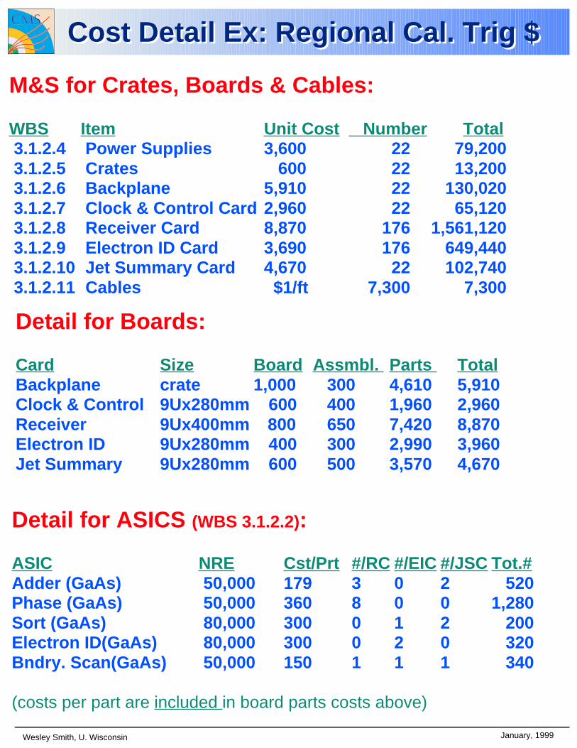
Wesley Smith, U. Wisconsin January, 1999
M&S for Crates, Boards & Cables:
WBS Item Unit Cost Number Total 3.1.2.4 Power Supplies 3,600 22 79,200 3.1.2.5 Crates 600 22 13,200 3.1.2.6 Backplane 5,910 22 130,020 3.1.2.7 Clock & Control Card 2,960 22 65,120 3.1.2.8 Receiver Card 8,870 176 1,561,120 3.1.2.9 Electron ID Card 3,690 176 649,440 3.1.2.10 Jet Summary Card 4,670 22 102,740 3.1.2.11 Cables $1/ft 7,300 7,300
Cost Detail Ex: Regional Cal. Trig $Cost Detail Ex: Regional Cal. Trig $
Detail for Boards:
Card Size Board Assmbl. Parts TotalBackplane crate 1,000 300 4,610 5,910Clock & Control 9Ux280mm 600 400 1,960 2,960Receiver 9Ux400mm 800 650 7,420 8,870Electron ID 9Ux280mm 400 300 2,990 3,960 Jet Summary 9Ux280mm 600 500 3,570 4,670
Detail for ASICS (WBS 3.1.2.2):
ASIC NRE Cst/Prt #/RC #/EIC #/JSC Tot.#Adder (GaAs) 50,000 179 3 0 2 520 Phase (GaAs) 50,000 360 8 0 0 1,280 Sort (GaAs) 80,000 300 0 1 2 200 Electron ID(GaAs) 80,000 300 0 2 0 320 Bndry. Scan(GaAs) 50,000 150 1 1 1 340
(costs per part are included in board parts costs above)
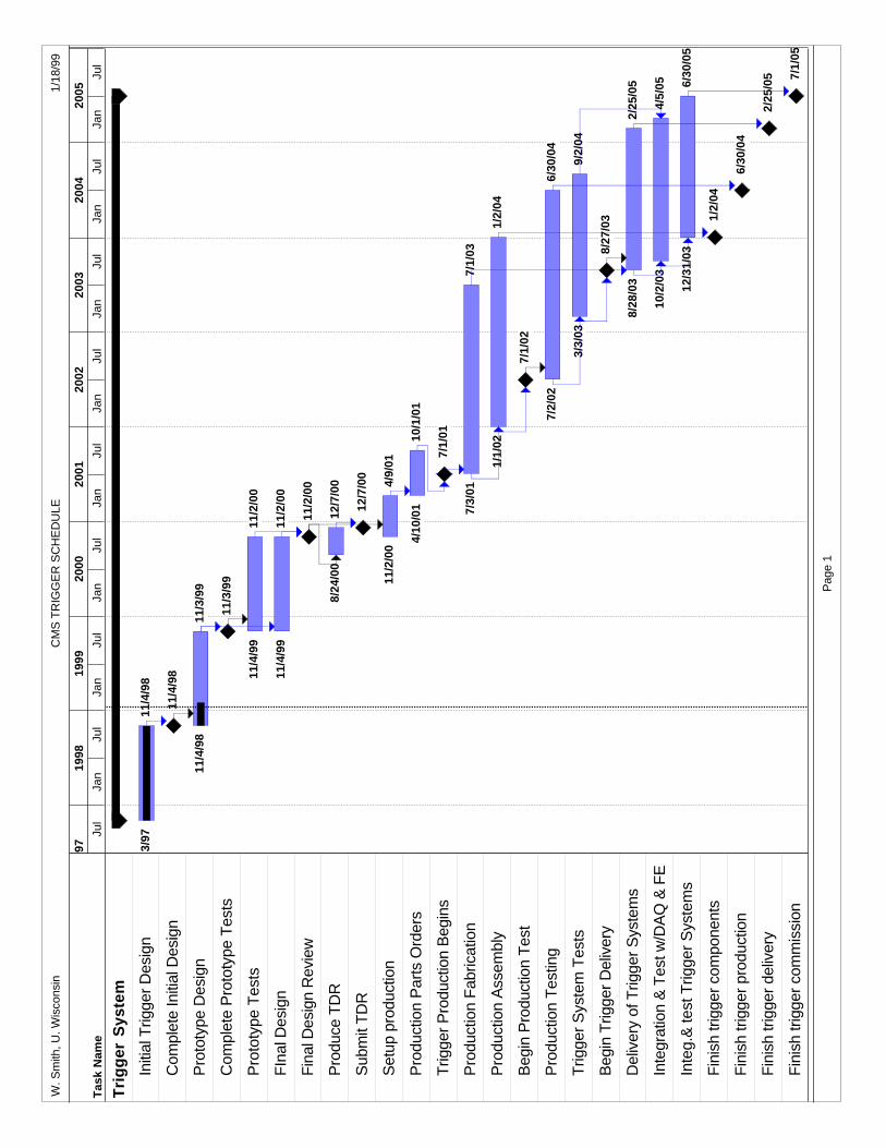
Tas
k N
ame
Tri
gg
er S
yste
m
Initi
al T
rigge
r D
esig
n
Com
plet
e In
itial
Des
ign
Pro
toty
pe D
esig
n
Com
plet
e P
roto
type
Tes
ts
Pro
toty
pe T
ests
FIn
al D
esig
n
Fin
al D
esig
n R
evie
w
Pro
duce
TD
R
Sub
mit
TD
R
Set
up p
rodu
ctio
n
Pro
duct
ion
Par
ts O
rder
s
Trig
ger
Pro
duct
ion
Beg
ins
Pro
duct
ion
Fab
ricat
ion
Pro
duct
ion
Ass
embl
y
Beg
in P
rodu
ctio
n T
est
Pro
duct
ion
Tes
ting
Trig
ger
Sys
tem
Tes
ts
Beg
in T
rigge
r D
eliv
ery
Del
iver
y of
Trig
ger
Sys
tem
s
Inte
grat
ion
& T
est w
/DA
Q &
FE
Inte
g.&
test
Trig
ger
Sys
tem
s
Fin
ish
trig
ger
com
pone
nts
Fin
ish
trig
ger
prod
uctio
n
Fin
ish
trig
ger
deliv
ery
Fin
ish
trig
ger
com
mis
sion
/3/9
711
/4/9
8
11/4
/98
11/4
/98
11/3
/99
11/3
/99
11/4
/99
11/2
/00
11/4
/99
11/2
/00
11/2
/00
8/24
/00
12/7
/00
12/7
/00
11/2
/00
4/9/
01
4/10
/01
10/1
/01
7/1/
01
7/3/
017/
1/03
1/1/
021/
2/04
7/1/
02
7/2/
026/
30/0
4
3/3/
039/
2/04
8/27
/03
8/28
/03
2/25
/05
10/2
/03
4/5/
05
12/3
1/03
6/30
/05
1/2/
04
6/30
/04
2/25
/05 7/
1/05
Jul
Jan
Jul
Jan
Jul
Jan
Jul
Jan
Jul
Jan
Jul
Jan
Jul
Jan
Jul
Jan
Jul
997
1998
1999
2000
2001
2002
2003
2004
2005
W. S
mith
, U. W
isco
nsin
CM
S T
RIG
GE
R S
CH
ED
ULE
1/18
/99
Pag
e 1

Janu
ary,
199
9W
esle
y S
mith
, U. W
isco
nsin
Ex:
CS
C T
rig
ger
Sch
edu
leE
x: C
SC
Tri
gg
er S
ched
ule
Fin
ish
Initi
al D
esig
nM
ay 1
3
Beg
in P
roto
type
Des
ign
Oct
1
Fin
ish
Pro
toty
pe D
esig
nM
ay 1
3
Beg
in P
roto
type
Con
stru
ctio
nA
pr 2
Fin
ish
Pro
toty
pe C
onst
ruct
ion
Sep
30
Beg
in P
roto
type
Tes
tA
ug 2
0
FIn
ish
Pro
toty
pe T
est
Jul 2
1
Beg
in F
inal
Des
ign
Jun
12
Fin
ish
Fin
al D
esig
nJu
l 22
Beg
in P
rodu
ctio
nJa
n 22
Fin
ish
Pro
duct
ion
Nov
25
Beg
in In
stal
latio
nA
ug 2
0
Fin
ish
Inst
alla
tion
Apr
29
Beg
in T
rigge
r S
yste
m T
ests
Apr
30
Fin
ish
Trig
ger
Sys
tem
Tes
tsS
ep 9
Oct
Apr
Oct
Apr
Oct
Apr
Oct
Apr
Oct
Apr
Oct
Apr
Oct
Apr
Oct
Apr
Oct
Apr
Oct
Apr
1996
1997
1998
1999
2000
2001
2002
2003
2004
2005

Wesley Smith, U. Wisconsin January, 1999
Trigger Milestone ListTrigger Milestone List Level 1 (1998-2000)
• Nov. 1998 Complete Initial Trigger Design:• Algorithms finalized
• Functional blocks determined
• Numbers of ASICs, boards, cards and crates specified
• Interfaces specified
• Trigger geometry determined
• Nov. 1999 Complete Phase 1 Prototype Design:• Designs of boards, cards
• ASICs for prototype tests done
• Nov. 2000 Phase 1 Prototype Tests Finished:• All tests necessary to begin design of production electronics
are complete
• Nov. 2000 Technical Design Report
Level 2 (1998-2000)• Nov. 1998:
• Complete Initial Muon Trigger Design
• Complete Initial Calorimeter Trigger Design
• Complete Initial Global Trigger Design
• Nov. 1999:• Complete Prototype Muon Trigger Design
• Complete Prototype Calorimeter Trigger Design
• Complete Prototype Global Trigger Design
• Nov. 2000:• Prototype Muon Trigger Tests Finished
• Prototype Calorimeter Trigger Tests Finished
• Prototype Global Trigger Tests Finished

Wesley Smith, U. Wisconsin January, 1999
Trigger Milestone ProgressTrigger Milestone Progress 1998 L1 Milestone:
• Nov. 1998 Complete Initial Trigger Design:• Algorithms finalized• Functional blocks determined • Numbers of ASICs, boards, cards and
crates specified• Interfaces specified• Trigger geometry determined
• Status: Complete
1998 L2 Milestones:• Nov. 1998:
• Complete Initial Muon Trigger Design• http://cmsdoc.cern.ch/ftp/afscms/TRIDAS/mutrig/html/
• Complete Initial Calorimeter Trigger Design• http://cmsdoc.cern.ch/ftp/afscms/TRIDAS/caltrig/html/
CalTrig.html
• Complete Initial Global Trigger Design• http://sungraz.cern.ch/CMS/trigger/globalTrigger/
Welcome.html
• Status: Complete
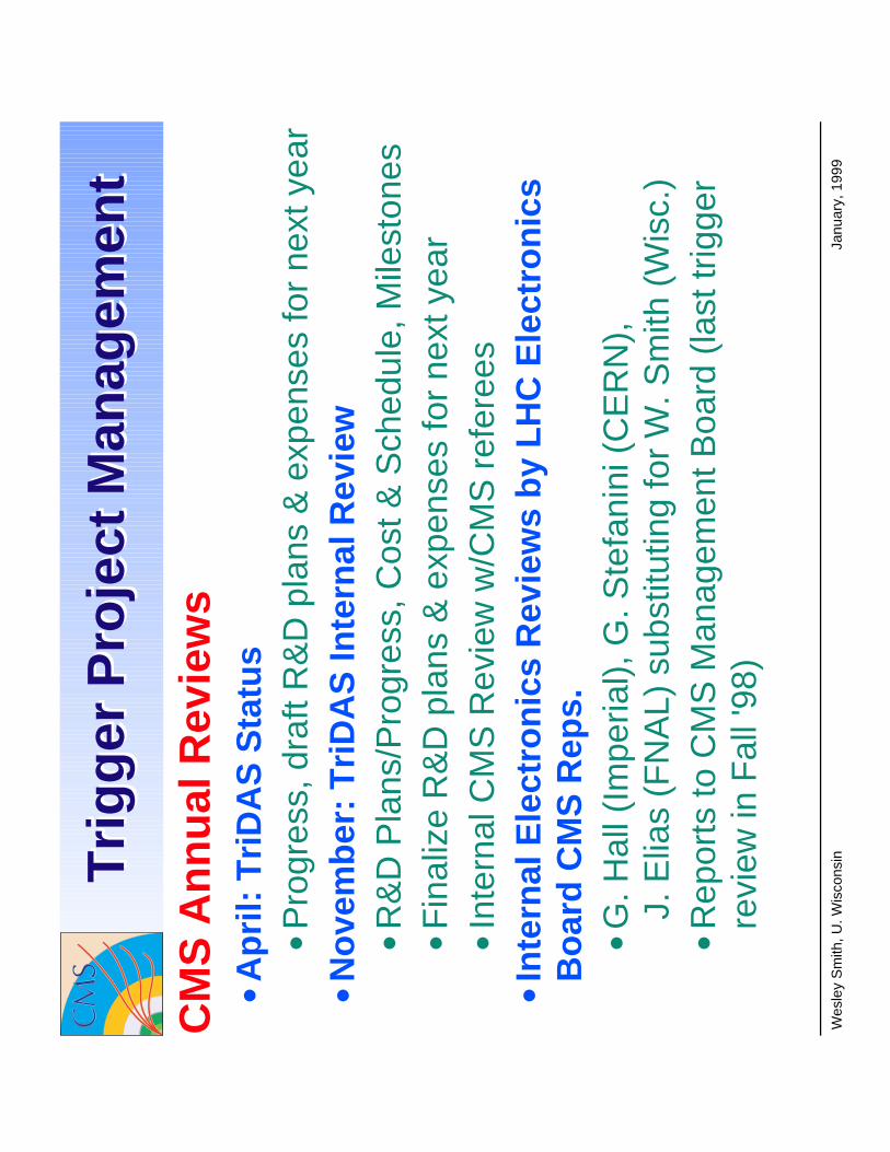
Janu
ary,
199
9W
esle
y S
mith
, U. W
isco
nsinTri
gg
er P
roje
ct M
anag
emen
tT
rig
ger
Pro
ject
Man
agem
ent
CM
S A
nn
ual
Rev
iew
s•A
pri
l: T
riD
AS
Sta
tus
•Pro
gres
s, d
raft
R&
D p
lans
& e
xpen
ses
for
next
yea
r•N
ove
mb
er:
Tri
DA
S In
tern
al R
evie
w•R
&D
Pla
ns/P
rogr
ess,
Cos
t & S
ched
ule,
Mile
ston
es•F
inal
ize
R&
D p
lans
& e
xpen
ses
for
next
yea
r•I
nter
nal C
MS
Rev
iew
w/C
MS
ref
eree
s•I
nte
rnal
Ele
ctro
nic
s R
evie
ws
by
LH
C E
lect
ron
ics
Bo
ard
CM
S R
eps.
•G. H
all (
Impe
rial),
G. S
tefa
nini
(C
ER
N),
J. E
lias
(FN
AL)
sub
stitu
ting
for
W. S
mith
(W
isc.
)•R
epor
ts to
CM
S M
anag
emen
t Boa
rd (
last
trig
ger
revi
ew in
Fal
l '98
)
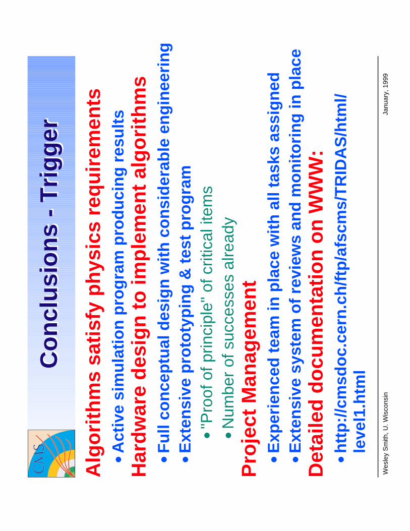
Janu
ary,
199
9W
esle
y S
mith
, U. W
isco
nsin
Co
ncl
usi
on
s -
Tri
gg
erC
on
clu
sio
ns
- T
rig
ger
Alg
ori
thm
s sa
tisf
y p
hys
ics
req
uir
emen
ts•A
ctiv
e si
mu
lati
on
pro
gra
m p
rod
uci
ng
res
ult
s H
ard
war
e d
esig
n t
o im
ple
men
t al
go
rith
ms
•Fu
ll co
nce
ptu
al d
esig
n w
ith
co
nsi
der
able
en
gin
eeri
ng
•Ext
ensi
ve p
roto
typ
ing
& t
est
pro
gra
m•"
Pro
of o
f prin
cipl
e" o
f crit
ical
item
s•N
umbe
r of
suc
cess
es a
lread
y
Pro
ject
Man
agem
ent
•Exp
erie
nce
d t
eam
in p
lace
wit
h a
ll ta
sks
assi
gn
ed•E
xten
sive
sys
tem
of
revi
ews
and
mo
nit
ori
ng
in p
lace
Det
aile
d d
ocu
men
tati
on
on
WW
W:
•htt
p:/
/cm
sdo
c.ce
rn.c
h/f
tp/a
fscm
s/T
RID
AS
/htm
l/le
vel1
.htm
l