triode electronics dynaco st-70 input board
TRANSCRIPT

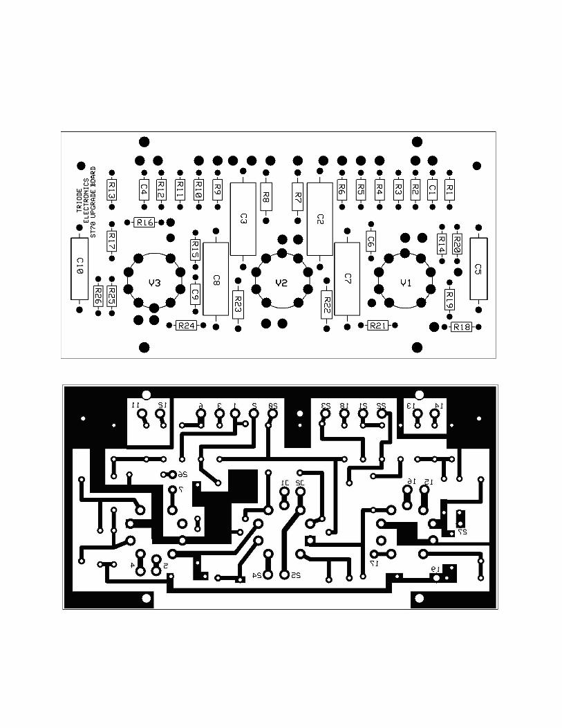
Triode ElectronicsDynaco ST-70 Input Board
SDS Labs
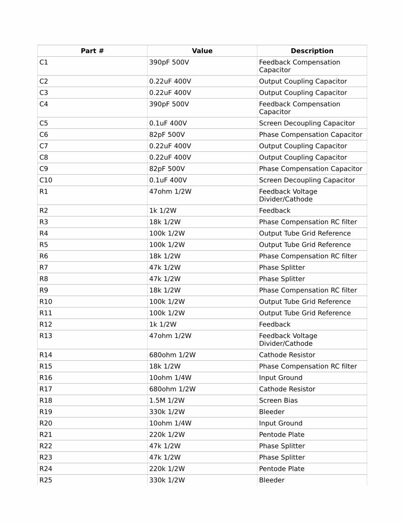
Part # Value Description
C1 390pF 500V Feedback Compensation Capacitor
C2 0.22uF 400V Output Coupling Capacitor
C3 0.22uF 400V Output Coupling Capacitor
C4 390pF 500V Feedback Compensation Capacitor
C5 0.1uF 400V Screen Decoupling Capacitor
C6 82pF 500V Phase Compensation Capacitor
C7 0.22uF 400V Output Coupling Capacitor
C8 0.22uF 400V Output Coupling Capacitor
C9 82pF 500V Phase Compensation Capacitor
C10 0.1uF 400V Screen Decoupling Capacitor
R1 47ohm 1/2W Feedback Voltage Divider/Cathode
R2 1k 1/2W Feedback
R3 18k 1/2W Phase Compensation RC filter
R4 100k 1/2W Output Tube Grid Reference
R5 100k 1/2W Output Tube Grid Reference
R6 18k 1/2W Phase Compensation RC filter
R7 47k 1/2W Phase Splitter
R8 47k 1/2W Phase Splitter
R9 18k 1/2W Phase Compensation RC filter
R10 100k 1/2W Output Tube Grid Reference
R11 100k 1/2W Output Tube Grid Reference
R12 1k 1/2W Feedback
R13 47ohm 1/2W Feedback Voltage Divider/Cathode
R14 680ohm 1/2W Cathode Resistor
R15 18k 1/2W Phase Compensation RC filter
R16 10ohm 1/4W Input Ground
R17 680ohm 1/2W Cathode Resistor
R18 1.5M 1/2W Screen Bias
R19 330k 1/2W Bleeder
R20 10ohm 1/4W Input Ground
R21 220k 1/2W Pentode Plate
R22 47k 1/2W Phase Splitter
R23 47k 1/2W Phase Splitter
R24 220k 1/2W Pentode Plate
R25 330k 1/2W Bleeder
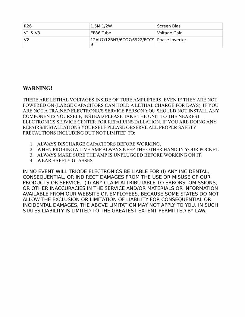
R26 1.5M 1/2W Screen Bias
V1 & V3 EF86 Tube Voltage Gain
V2 12AU7/12BH7/6CG7/6922/ECC99
Phase Inverter
WARNING!
THERE ARE LETHAL VOLTAGES INSIDE OF TUBE AMPLIFIERS, EVEN IF THEY ARE NOT POWERED ON (LARGE CAPACITORS CAN HOLD A LETHAL CHARGE FOR DAYS). IF YOU ARE NOT A TRAINED ELECTRONICS SERVICE PERSON YOU SHOULD NOT INSTALL ANY COMPONENTS YOURSELF, INSTEAD PLEASE TAKE THE UNIT TO THE NEAREST ELECTRONICS SERVICE CENTER FOR REPAIR/INSTALLATION. IF YOU ARE DOING ANY REPAIRS/INSTALLATIONS YOURSELF PLEASE OBSERVE ALL PROPER SAFETY PRECAUTIONS INCLUDING BUT NOT LIMITED TO:
1. ALWAYS DISCHARGE CAPACITORS BEFORE WORKING.2. WHEN PROBING A LIVE AMP ALWAYS KEEP THE OTHER HAND IN YOUR POCKET.3. ALWAYS MAKE SURE THE AMP IS UNPLUGGED BEFORE WORKING ON IT.4. WEAR SAFETY GLASSES
IN NO EVENT WILL TRIODE ELECTRONICS BE LIABLE FOR (I) ANY INCIDENTAL, CONSEQUENTIAL, OR INDIRECT DAMAGES FROM THE USE OR MISUSE OF OUR PRODUCTS OR SERVICE. (II) ANY CLAIM ATTRIBUTABLE TO ERRORS, OMISSIONS, OR OTHER INACCURACIES IN THE SERVICE AND/OR MATERIALS OR INFORMATION AVAILABLE FROM OUR WEBSITE OR EMPLOYEES. BECAUSE SOME STATES DO NOT ALLOW THE EXCLUSION OR LIMITATION OF LIABILITY FOR CONSEQUENTIAL OR INCIDENTAL DAMAGES, THE ABOVE LIMITATION MAY NOT APPLY TO YOU. IN SUCH STATES LIABILITY IS LIMITED TO THE GREATEST EXTENT PERMITTED BY LAW.
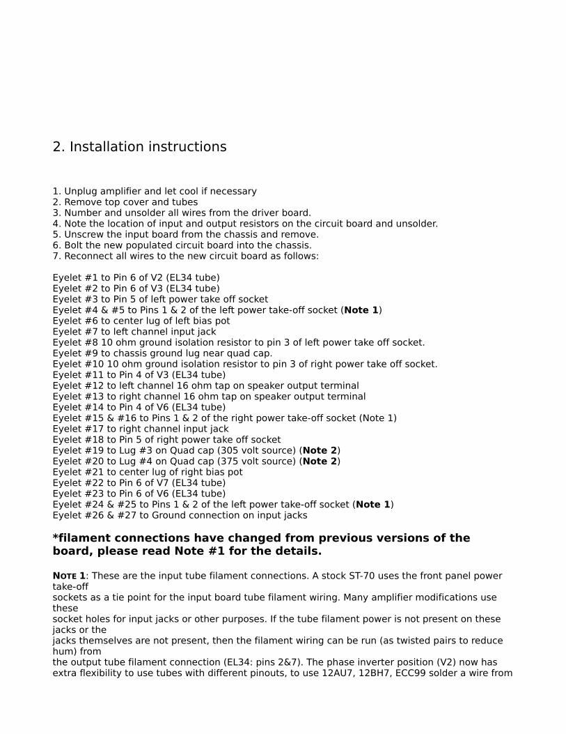
2. Installation instructions
1. Unplug amplifier and let cool if necessary2. Remove top cover and tubes3. Number and unsolder all wires from the driver board.4. Note the location of input and output resistors on the circuit board and unsolder.5. Unscrew the input board from the chassis and remove.6. Bolt the new populated circuit board into the chassis.7. Reconnect all wires to the new circuit board as follows:
Eyelet #1 to Pin 6 of V2 (EL34 tube)Eyelet #2 to Pin 6 of V3 (EL34 tube)Eyelet #3 to Pin 5 of left power take off socketEyelet #4 & #5 to Pins 1 & 2 of the left power take-off socket (Note 1)Eyelet #6 to center lug of left bias potEyelet #7 to left channel input jackEyelet #8 10 ohm ground isolation resistor to pin 3 of left power take off socket.Eyelet #9 to chassis ground lug near quad cap.Eyelet #10 10 ohm ground isolation resistor to pin 3 of right power take off socket.Eyelet #11 to Pin 4 of V3 (EL34 tube)Eyelet #12 to left channel 16 ohm tap on speaker output terminalEyelet #13 to right channel 16 ohm tap on speaker output terminalEyelet #14 to Pin 4 of V6 (EL34 tube)Eyelet #15 & #16 to Pins 1 & 2 of the right power take-off socket (Note 1)Eyelet #17 to right channel input jackEyelet #18 to Pin 5 of right power take off socketEyelet #19 to Lug #3 on Quad cap (305 volt source) (Note 2)Eyelet #20 to Lug #4 on Quad cap (375 volt source) (Note 2)Eyelet #21 to center lug of right bias potEyelet #22 to Pin 6 of V7 (EL34 tube)Eyelet #23 to Pin 6 of V6 (EL34 tube)Eyelet #24 & #25 to Pins 1 & 2 of the left power take-off socket (Note 1)Eyelet #26 & #27 to Ground connection on input jacks
*filament connections have changed from previous versions of the board, please read Note #1 for the details.
NOTE 1: These are the input tube filament connections. A stock ST-70 uses the front panel power take-offsockets as a tie point for the input board tube filament wiring. Many amplifier modifications use thesesocket holes for input jacks or other purposes. If the tube filament power is not present on these jacks or thejacks themselves are not present, then the filament wiring can be run (as twisted pairs to reduce hum) fromthe output tube filament connection (EL34: pins 2&7). The phase inverter position (V2) now has extra flexibility to use tubes with different pinouts, to use 12AU7, 12BH7, ECC99 solder a wire from
J1 to J2 and make your filament connections to eyelets 24 & 25, to use 6CG7, 6922, 7308, or 6DJ8 do not jumper J1 and J2 and instead make your filament connections to J1 and J2 and ignore eyelets 24 and 25.
NOTE 2: If using a replacement power supply board, attach these points to the appropriate points of thereplacement board.
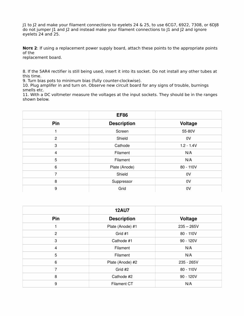
8. If the 5AR4 rectifier is still being used, insert it into its socket. Do not install any other tubes at this time.9. Turn bias pots to minimum bias (fully counter-clockwise).10. Plug amplifer in and turn on. Observe new circuit board for any signs of trouble, burnings smells etc.11. With a DC voltmeter measure the voltages at the input sockets. They should be in the ranges shown below.
EF86
Pin Description Voltage1 Screen 5580V
2 Shield 0V
3 Cathode 1.2 1.4V
4 Filament N/A
5 Filament N/A
6 Plate (Anode) 80 110V
7 Shield 0V
8 Suppressor 0V
9 Grid 0V
12AU7
Pin Description Voltage1 Plate (Anode) #1 235 – 265V
2 Grid #1 80 110V
3 Cathode #1 90 120V
4 Filament N/A
5 Filament N/A
6 Plate (Anode) #2 235 265V
7 Grid #2 80 110V
8 Cathode #2 90 120V
9 Filament CT N/A
NOTES:(a) 12BH7 tubes will have slightly higher cathode voltages and slightly lower plate voltages.(b) The output tube voltages can be found in the original Dyna assembly manual included in the appendix.(c) Filaments should have 6.3V AC across them (the 12AU7 have 6.3V AC across the Filament cap andthe Filament ends).12. Turn off amplifier and install the output tubes and driver tubes.13. Turn amplifier on, and bias as per instructions in the original Dyna Manual. If 10ohm resistors are used for bias-set remember you voltage will be 1V and not the 1.56V in the Dynaco manual14. Enjoy
3. Output tube changesThe original Triode electronics board design manual included modifications to this board and to the amplifier toallow using other output tubes in a ST-70. It is being included here to allow the owner to experiment, and to showthe flexibility of the design.
3.1 Bias circuit modificationsThe bias circuit has been designed to provide the proper bias voltage levels to EL34 tubes. This is not an appropriaterange for some other types of output tubes. The range can be extended by the following changes:
*Replace the original 10K bias potentiometers with 20K or 30K linear potentiometers. It is recommended touse a 2 or 3 watt unit (for robustness in the event of a tube failure), however a 1.2 wattt unit will work fine.
*Replace the two 10K bias resistors on either side of the bias potentiometer and replace them with watt 4.7K parts. Turncontrols full counterclockwise before turning amplifier on, and rebias output tubes.
3.2 6550, KT88 and KT90 tubesThe tube will operate properly in the finished amplifier provided the above bias modification is made, however torun these tubes run at book spec regarding limitations on grid circuit DC resistance, and for maximum stability,the following modifications should be made:
*Change 12AU7 tube for a 12BH7 tube.
*R7, R8, R22 and R23 to 22K (matched to 1%)
*Change R4, R5, R10, and R11 to 47K (matched to 1
*Install new tubes and bias according to factory manual.
NOTE: Other rectifier tubes with filament voltages over 2A should not be used with the KT88 family

oftubes or a transformer overload will occur.
3.3 8417 tubesThe tubes should operate properly after making the above bias supply modification. If problems exist, try thefollowing:
*Proper bias point out of range of the controls: Reduce the value of the bias resistor between the biaspotentiometers and ground to a value of about 2K.
*Motorboating (low frequency oscillation), Tube runaway (Plates turn orange or red on one tube), orunstable bias voltage: Reduce the size of R7, R8, R22 and R23 to a value of 18 33K. If motorboatingcontinues, increase the value of R2 and R12 to a value of 1.8 2.2K.
3.4 6L6GC, 5881, 7581, EL37, EL38(6CN6), KT66, 350B, 350A, 807, 7027A tubesThese tubes should operate properly in the finished amplifier with the above bias supply changes. Some listedtube types will require output tube socket wiring changes, and or an anode plate cap. See the tube manual for thetype out output tube used for this information.Since these output tubes reduce the open-loop gain of the amplifier, you may wish to reduce the values of thefeedback resistors R2 and R12 slightly.
3.5 Triode operation of EL34, 6550, KT88, and 6L6GC tubesDisconnect leads from pin 4 of each output tube socket and insulate the leads. Install 100 ohm resistors frombetween pins 3 and 4 of each socket. Rebias amplifier as described in the original Dyna manual.Since these output tubes reduce the open-loop gain of the amplifier, you may wish to reduce the values of thefeedback resistors R2 and R12 slightly.
3.5.1 2A3, 6A3, 6A5-G and 6B4-G tubesThese tubes require more extensive amplifier modifications than the others listed above. Follow these generalprocedures:*Disconnect screen tap leads from pin 4 of each output tube socket and insulate the ends of the leads.
*Disconnect and remove the filament leans and biaset resistors from all output tube sockets.
*For 2A3 and 6A3 tubes, install new 4-pin tube sockets.
*Change R4, R5, R10, and R11 to 220K (matched to 1%)
*R7, R8, R22 and R23 to 22K (matched to 1%)
*Change 12AU7 tube to a 12BH7 tube
*Disconnect the wires from eyelets #6 & #21 (the wires can also be disconnected from the bias supply andremoved) and ground eyelets #6 & #21. The bias supply and controls can be removed, as they are
not usedin this design.
*A separate filament transformer or the appropriate current and voltage for the selected output tubes must beinstalled (inboard or outboard) for each pair of output tubes. (example for 2A3 tubes: 2.5V 5A).
*Connect each filament transformer secondaries to a pair of output tube filaments. The pairs of output tubefilaments are run in parallel and also function as the cathode.
*Bias voltage is generated by a common cathode resistor of about 800 Ohms (20 watts) connected from thefilament pair and ground. This is instered in one of two places: a) Between the center tap of the filamenttransformer secondary and ground. Or b) By attaching a 25 ohm (2 watt) potentiometer across each filamentsecondary and then attaching the 800 ohm resistor between the potentiometer wiper and ground.
*Attach a 100 uF (minimum) 150V cap in parallel with each 800 ohm cathode resistor. The positive end ofthe capacitor should be attached to the filament end of the cathode resistor.
*The cathode resistors should be mounted in such a way to allow heat to dissipate and away from flammableor meltable items.
*Since these output tubes reduce the open-loop gain of the amplifier, you may wish to reduce the values of thefeedback resistors R2 and R12 slightly.
4. Changing Circuit ValuesAn oscilloscope is an invaluable tool when making circuit changes. Only minimal circuit changes should beattempted without an oscilloscope (you are blind in that condition).
4.1 Testing driver circuit gain and output voltageThe driver circuit must be able to provide an undistorted AC signal voltage to each output tube equal or greaterthan the bias voltage in order for the amplifier to produce its maximum output. To test the driver board, removethe output tubes, this also disconnects the feedback loop. An input signal (produced by a test CD or functiongenerator) is applied to the amplifier input and the output of the driver board is measured at the output tube gridresistors (R4, R5, R10, and R11).
4.2 Output Tube DC Grid Resistance (R4, R5, R10, and R11)On this driver board, the value of these has been reduced to 100K rather than 270K as in the original, this wasdome principally to extend the circuit bandwidth and to be more stable with some EL34s which draw additionalgrid current. The value of these resistors may be varied to match the particular output tube type selected so long asso long as excessive distortion does not result from overloading the phase splitter tube. The values of the couplingcapacitors (C2, C3, C7 and C8) will need to be changed in proportion to the value change of these
resistors. Forexample if the resistors value is halved, the capacitor values must be doubled.
4.3 Phase splitter Resistors (R7, R8, R22, and R23)The value of these resistors may be varied from 10K to 100K provided that: a) they are matched for each halfof the splitter tube. b) The output tube grid resistors (R4, R5, R10, and R11) are at least twice the value of thephase splitter resistors. If a phase splitter resistor of 22K or less is used, then the 12AU7 should be replaced witha 12BH7. Resistors of 33K or lower need to be at least 1 watt rating and resistors 18K or lower need to be 2 watts.
4.4 EF86 Plate, Cathode, and Screen Resistors (R21, R24, R18, R26, R14, and R17)The EF86 plate load resistors (R21 and R24) set the gain of the driver board and limit the amount of current drawnby the tube. Considerable variation to the values of these resistors may be made (values between 100K to 330Kare typically used) provided the following is observed:The values of the screen grid resistors (R18 and R26) are generally made proportional to the changes inthe plate load resistors. If the plate load resistors are reduced, the screen grid should be reduced by the samepercentage.After making any changes to R18, R21, R24, and R26 the bias of the EF86 must be adjusted manually bychanging the cathode resistors (R14 and R17) and bleeder resistors (R19 and R25) to produce a plate voltage (pin6 of EF86) between 80 and 115 volts. If the EF86 plate voltage is out of this range, the phase splitter will not beable to swing sufficient voltage to drive the output tubes. Decreasing the value of R19/R25 or increasing the valueof R14/R17 will increase plate voltage.
4.5 Triode connecting EF86Triode connection of the EF86 may be accomplished be removing R18/R26 and jumpering pins 6 & 7 of theEF86 together, then making changes to R19/R25 and R14/R17 as described above to bring the plate voltage backto the proper range . Since the plate current in triode mode is considerably higher, the cathode resistor values(R14/R17) will have to be made considerably larger. The voltage gain from the EF86 is reduced from 180-200down to 24-32. This reduces the open loop gain of the amplifier as well as its sensitivity.
4.6 Other Resistors on the BoardThe other resistors on the board should not need to be changed.
4.7 Coupling Capacitors (C2, C3, C7, and C8) and Screen Decoupling Capacitors (C5,C10)The values of these components may be varied considerably, taking into account that too small a value will cause a
low frequency rolloff, and too large a value may cause Motorboating. Electrolytic capacitors should not be used,and paper types other than hermetically sealed paper-oil types should not be used. Otherwise about any othermaterial is acceptable.
4.8 Other Capacitors on the BoardThese are high frequency phase compensation capacitors whose values are set by the output transformer characteristics.These should not be changed.
5. General TroubleshootingThese are suggestions and some basic guidance; this is by no means an exhaustive list.
5.1 Low B+ voltage from 5AR4 or rectifier diodesThis indicates either a restriction in the power supply such as open windings in the power transformer or choke, ora bad rectifier tube, or excessive current draw. Excessive current draw can be caused by shorted output transformers,bad output tubes, leaky coupling capacitors, or leaky filter capacitors in the power supply. To troubleshoot:
*Test or substitute the rectifier tube, if using diodes, check for a shorted diode.
*Check for continuity in the rectifier plate leads (pins 4 & 6), lack of continuity indicates a problem withthe B+ voltage winding in the power transformer or a bad solder joint between the transformer and the testpoints.
*Discharge all filter capacitors be powering off the amplifer and waiting a few minutes, then shorting theterminals to ground with a low value power resistor. Using an ohmmeter, check the resistance of eachcapacitor in the power supply. When first measuring a capacitor, the meter should read nearly a short, thenit should steadily climb to a high value. If one of the sections will not rise in resistance, this indicates adefective capacitor.
*Pull the output tubes, and disconnect the output transformer center taps from the power supply. Measure theresistance from the transformer primary lead to ground, the reading should be very high (infinite ideally).A low value indicates a short from the transformer primary to ground.
5.2 All output tubes draw too much current (glowing plates)Check voltages in the bias circuit, the voltage at Eyelets #6 & #21 should be 20 to 40 volts. Of the bias voltageappears normal, check for an excessive voltage drop across R4, R5, R10, and R11. If a drop of more than a fewvolts is found across any one of them, a severe tube imbalance or defective tube is most likely the culprit.
5.3 One set of output tubes draws too much current (glowing plates)Swap the offending set of tubes to the other channel. If the problem follows the tubes, then a bad
tube is theculprit. If the problem does not switch channels, suspect the bias circuit, particularly a bas bias potentiometer.Also check for a bad tube socket, or leaky coupling capacitor.
5.4 One tube glows red or orangeSwap the offending tube with another in the amplifier. If the problem follows the tube, it is bad. Before replacing,try resoldering the tube pins at the base. If the problem does not follow the tube, suspect a faulty tube socket, asocket mis-wiring, or a leaky coupling capacitor.
5.5 Transformer hot or vibrating excessivelyThis indicates that the amplifier is drawing excessive current due to leakage. See above to track down excessivecurrent draw. All transformers vibrate to some extent, and some Dyna factory transformers tend to vibrate morethan most users would like. This in itself does not indicate a problem. Likewise, all transformers get hot whileworking, but should not cause skin burns.
5.6 Capacitors bubbling, crackling, venting or smokingThis indicates that a capacitors was exposed to a voltage above its rating, or was reverse biased in the case ofelectrolytic capacitors, or is simply defective. Replace the offending capacitor, and examine the circuit around thecapacitor for mis-wiring or other problems.
5.7 Resistors overheating or smokingThis indicates that a resistor of the wrong wattage rating was used or that a problem in the circuit is causing alarger than normal voltage drop across the offending resistor. This is most likely a short in close proximity to theresistor in question, and most likely a defective capacitor or tube.
5.8 Crackling, hissing, or noises in one of both channelsFirst eliminate the tubes as the source of the problem by switching tubes across channel one by one if the problemexists in one channel only. If the problem persists, pull the tubes from the driver stage. If the noise still persists,then it is in the bias circuit, or output tube circuit. If the noise occurs in both channels, the power supply is themost likely culprit. Most noise problems you may encounter derive from the following sources; from most to leastcommon:
*Loose, dirty, or corroded sockets, pins or connectors. Tighten and clean or replace.
*Outside electromagnetic interference. Much can be said about the possible sources and solutions, the generalidea is to either shield the signal for picking up interference, eliminate the source of the noise, or shieldthe source to prevent it from emanating.
*Tubes. Substitute suspect tubes starting from the input.
*Bad solder joints. Reheat suspect solder joints to reflow the solder. If solder does not want to stick to ajoint, de-solder and thoroughly clean the two mating surfaces and re-solder.
*Broken or loose wires and leads. Inspect and repair as necessary
*Capacitors (particularly electrolytic) with intermittent shorts or leaks. The is common if the original powersupply capacitors have not been replaced.
*Cracked or overheated resistors. Often found in the power supply particularly if the original resistors havenot been replaced.
*Intermittent arcing inside the power or output transformer. This noise persists even if all the tubes have removed.
5.9 Excessive audio humThis is usually caused by one of the following:
*Ground loops, multiple ground paths, and bad ground connections. The audio system should be connectedto earth ground only at one point (normally the preamp) and ground connections must be good.
*Tubes with cathode heater shorts or leakage. AC is leaking from the heater circuit (pure AC) into cathodeto the audio circuit.
*Any audio connections (RCA jacks, tube pins, etc) open or not making good contact.
*Transformer vibration. Couples to the internal tube structures and modulate the audio signal. The culprit ismicrophonic tubes.