triple-band heavy duty submersible transceiver · phone audio, ear-phone audio, ptt, and ground....
TRANSCRIPT

VERTEX STANDARD CO., LTD.4-8-8 Nakameguro, Meguro-Ku, Tokyo 153-8644, Japan
VERTEX STANDARDUS Headquarters17210 Edwards Rd., Cerritos, CA 90703, U.S.A.International Division8350 N.W. 52nd Terrace, Suite 201, Miami, FL 33166, U.S.A.
YAESU EUROPE B.V.P.O. Box 75525, 1118 ZN Schiphol, The Netherlands
YAESU UK LTD.Unit 12, Sun Valley Business Park, Winnall CloseWinchester, Hampshire, SO23 0LB, U.K.
VERTEX STANDARD HK LTD.Unit 5, 20/F., Seaview Centre, 139-141 Hoi Bun Road,Kwun Tong, Kowloon, Hong Kong
50/144/430 MHzTRIPLE-BAND HEAVY DUTY
SUBMERSIBLE TRANSCEIVER
OPERATING MANUAL

ContentsMemory Mode .............................................................. 45
Regular Memory Operation ...................................... 46Memory Storage ................................................... 46Storing Independent Transmit Frequencies(“Odd Split”) ........................................................ 46Memory Recall ..................................................... 47HOME Channel Memory ..................................... 47Labeling Memories ............................................... 48Memory Offset Tuning ......................................... 49Masking Memories ............................................... 50Memory Group Operation ................................... 51Moving Memory Data to the VFO ...................... 52Memory Only Mode ............................................. 52
Hyper Memory Operation ......................................... 53One-Touch Memory Operation ................................ 54Sort-wave Broadcast Station Memory Channels ..... 55VHF Marine Memory Channels ............................... 56
Scanning ......................................................................... 57VFO Scanning ........................................................... 58Memory Scanning ...................................................... 58
Temporary Memory Skip ..................................... 59How to Skip (Omit) a ChannelDuring Memory Scan Operation .......................... 59Preferential Memory Scan .................................... 60
Programmable (Band Limit) Memory Scan (PMS) . 61“Priority Channel” Scanning (Dual Watch) ............. 61Automatic Lamp Illumination on Scan Stop ............ 62Band Edge Beeper ..................................................... 62Spectrum Analyzer Operation ................................... 63Smart Search Operation ............................................ 64Channel Counter Operation ...................................... 66Internet Connection Feature ...................................... 67
Sensor Mode .................................................................. 68Sensor Mode Option ................................................. 69
Clock Set .............................................................. 69Selecting the Wave Form Display ....................... 70Selecting the Unit of Temperature Display ......... 70Selecting the Unit ofAtmospheric Pressure Meter (Barometer) ........... 70Correcting the Atmospheric Pressure Meter(Barometer Offset) ............................................... 70Selecting the Unit of Altimeter ............................ 71Correcting the Altimeter Setting(Altimeter Offset) ................................................. 71
Timer Operation ........................................................... 72Display Customization ................................................. 73
Icon Mode .................................................................. 73Icon Selection ............................................................ 73Icon Editor ................................................................. 74Power-Off Display Mode .......................................... 75S-and TX Power Meter Symbols .............................. 76Font Editor ................................................................. 77Display Contrast ........................................................ 78Display Dimmer ......................................................... 78STROBE Customization ........................................... 79
Reset Procedures .......................................................... 80Cloning ........................................................................... 81Set Mode ........................................................................ 82Installation of the SU-1 ................................................ 97Specifications ................................................................. 98Appendix ...................................................................... 100
Introduction ..................................................................... 1Controls & Connections ................................................. 2Display Icons & Indicators ............................................ 3Keypad Function ............................................................ 4Accessories & Options ................................................... 6Installation of Accessories ............................................. 7
Antenna Installation ..................................................... 7How to Install the Quick Draw Belt Clip ................... 8Installation of FNB-80LI Battery Pack ....................... 8Installation of FBA-23 (option)
Alkaline Battery Case ............................................. 9Battery Life Information ............................................ 10AC Operation Using NC-72 ..................................... 10
Interface of Packet TNCs ............................................ 11Operation ....................................................................... 12
Switching Power On and Off .................................... 12Adjusting the Volume Level ..................................... 12Squelch Adjustment ................................................... 13Selecting the Operating Band .................................... 14Selecting the Frequency Band ................................... 15Frequency Navigation ................................................ 16Audio Muting ............................................................. 17BAND Link ................................................................ 17Transmission .............................................................. 17
Changing the Transmitter Power Level ............... 18VOX Operation ......................................................... 19AM Broadcast Reception .......................................... 20AM Aircraft Reception .............................................. 20FM Broadcast/TV Audio Reception ......................... 21Weather Broadcast Reception .................................. 22Keyboard Locking ..................................................... 23Keypad/LCD Illumination ......................................... 24Disabling the Keypad Beeper ................................... 24
Advanced Operation .................................................... 25Setting the Frequency Display Image Size ............... 25Changing the Channel Steps ..................................... 25Changing the Operating Mode .................................. 26Repeater Operation .................................................... 27CTCSS Operation ...................................................... 30DCS Operation .......................................................... 31Tone Search Scanning ............................................... 32CTCSS/DCS Bell Operation ..................................... 33Split Tone Operation ................................................. 33Tone Calling (1750 Hz) ............................................ 34ARTS (Automatic Range Transponder System) ...... 35DTMF Operation ....................................................... 38Emergency Channel Operation ................................. 39ATT (Front End Attenuator) ..................................... 40Receive Battery Saver Setup ..................................... 40TX Battery Saver ....................................................... 41Disabling the “STROBE” ......................................... 41Automatic Power-Off (APO) Feature ....................... 42Transmitter Time-Out Timer (TOT) ......................... 42Busy Channel Lock-Out (BCLO) ............................. 43MIC Monitor ............................................................. 43Changing the TX Deviation Level ............................ 44

VX-7R OPERATING MANUAL 1
The VX-7R is a miniature 3-band FM transceiverwith extensive receive frequency coverage, provid-ing leading-edge features for VHF and UHF two-way amateur communications, along with unmatchedmonitoring capability.
The VX-7R’s small size allows you to take it any-where – hiking, skiing, or while walking around town– and its operating flexibility brings the user manyavenues of operating enjoyment. Besides 50, 144,and 430 MHz transceive operation, the VX-7R pro-vides 222 MHz QRP (0.3 Watts) transceive opera-tion, receive coverage of the AM (MF) and FMbroadcast bands, HF Shortwave Bands up to 16 MHz,VHF and UHF TV bands, the VHF AM aircraft band,and a wide range of commercial and public safetyfrequencies! Dual In-band Receive (V/V and U/U)lets you keep track of two active frequencies. Andthe optional Barometer pressure Sensor Unit providesreadout of barometric pressure and altitude whilemountain climbing or hiking, and it also generates aWeather Forecast based on measured data.
The transmitter section provides 5 Watts of cleanpower output on the FM operation on the 50 MHz,144 MHz, and 430 MHz bands with the suppliedFNB-80LI Battery Pack, and 0.3 Watts output on222 MHz, and 1 Watt of carrier output for AM op-eration on 50 MHz. Both CTCSS and DCS tone sig-naling formats are built into the VX-7R, in additionto Yaesu’s exclusive ARTSTM-(Auto-Range Tran-sponder System), which “beeps” the user when youmove out of communications range with anotherARTSTM-equipped station.
We appreciate your purchase of the VX-7R, and en-courage you to read this manual thoroughly, so as tolearn about the many exciting features of your excit-ing new Yaesu hand-held transceiver!
INTRODUCTION

VX-7R OPERATING MANUAL2
CONTROLS & CONNECTIONS
ANTENNAConnect the sup-plied rubber flex an-tenna (or anotherantenna presentinga 50-Ohm imped-ance) here.
VOLUMEThis control adjuststhe audio volumelevel. Clockwise ro-tation increases thevolume level.
DIALThe main tuningDial is used for set-ting the operatingfrequency, and alsois used for Menuse lec t i ons andother adjustments.
MIC/SPThis four-conductorminiature jack pro-vides connectionpoints for micro-phone audio, ear-phone audio, PTT,and ground.
EXT DCThis coaxial DCjack allows connec-tion to an externalDC power source(10-16V DC). Thecenter pin of thisjack is the Positive(+) line.
MICThe internal micro-phone is located atthe bottom right-hand corner of thedisplay.
STROBEThe STROBE isthe unique indica-tor which indicatesthe transceiver’sstatus.You may customizethe STROBE colorsetup via the Menumode.
PTT(“Push To Talk”)
Press this switchinward to transmit,and release it (toreceive) after yourt ransmiss ion iscompleted.
MONIPressing this keydisables the noisesquelching action,al lowing you tohear very weak sig-nals near the back-ground noise level.
(PWR) SwitchPress and hold thisswitch for 2 sec-onds to toggle thetransceiver’s poweron and off.
SPEAKERT h e i n t e r n a lspeaker is locateddirectly below thedisplay.
KEYBOARDThese 17 keys select many of themost important operating featureson the VX-7R.This function of the keys are de-scribed in details on pages 4 and 5.

VX-7R OPERATING MANUAL 3
DISPLAY ICONS & INDICATORS
ICON: Dual Watch Active (page 61)
: Key Lock Active (page 23): Repeater Shift Direction (page 27)
: Minus (–) Shift: Plus (+) Shifh: Odd Splits
: CTCSS/DCS Operation (page 30): Tone Encoder
: Tone Squelch: Digital Code Squelch (DCS): TX: Tone Encoder, RX: DCS Decoder: TX: DCS Encoder, RX: Tone Decoder
: DCS Encoder: Automatic Power-Off Active (page 42): Low TX Power Selected (page 18)
No Icon: High Power:Low Power 3:Low Power 2: Low Power 1
: Bell Alarm Active (page 33): DTMF Autodialer Active (page 39)
: Audio Mute Active (page 17): VOX Active (page 18): RF Front-end Attenuator Active (page 40)
: Battery Saver Active (page 40): Low Battery! (page 10)
OPERATING MODE
NFM: FMWFM: Wide FMAM: AM
FREQUENCY CONTROL
VFO: VFO Mode (page 15)MR: Memory Mode (page 45)MT: Memory Tume Mode (page 49)PMS: Programable Memory Scan Mode (page 61)WX: Weather Channel (page 22)Sea: Marine Channel (page 56)HYP: Hyper Memoy Mode (page 53)OTM: One Touch Memory Mode (page 54)LST: Short-wave Broadcast StationMemory (page 55)
“Main” Band Frequency
“Sub” Band Frequency“Main” Band Operating Mode
“Sub” Band Operating Mode
“Main” Band S- & PO Meter
“Sub” Band S- & PO Meter
“Main” BandFrequency Control
“Sub” BandFrequency Control

VX-7R OPERATING MANUAL4
KEYPAD FUNCTIONS
Press Key
Press and HoldKey
Press +
Press Key
Press and HoldKey
Press +
Press Key
Press and HoldKey
Press +
Frequency entrydigit “1”
Frequency entrydigit “2”
Frequency entrydigit “4”
Frequency entrydigit “5”
Frequency entrydigit “7”
Frequency entrydigit “8”
Activates the Scanner
Store the current settinginto the
Hyper Memory “1”
Store the current settinginto the
Hyper Memory “2”
Store the current settinginto the
Hyper Memory “4”
Store the current settinginto the
Hyper Memory “5”
Activates theDual Watch Feature
Activates the“Alternate” key Function
No Action
Activates the“Memory Write” mode(for memory channel
storage)
Reverses the transmitand receive frequencieswhile working through a
repeater
Switches operationto the “Home”
(favorite frequency)Channel
Activates theEMERGENCY Function
Activates theInternet Connection
Feature
Select the desiredtransmit power output
Activates theKey Lock Feature
Activates theChannel Counter
Feature
Activates theCTCSS or DCS
Operation
Store the current settinginto the
Hyper Memory “7”
Store the current settinginto the
Hyper Memory “8”
Activates theARTS Feature
Activates theSmart SearchTM
Feature

VX-7R OPERATING MANUAL 5
KEYPAD FUNCTIONS
Press Key
Press and HoldKey
Press +
Press Key
Press and HoldKey
Press +
Press Key
Press and HoldKey
Press +
Frequency entrydigit “3”
Frequency entrydigit “6”
Frequency entrydigit “9”
Frequency entrydigit “0”
Store the current settinginto the
Hyper Memory “3”
Store the current settinginto the
Hyper Memory “6”
Store the current settinginto the
Hyper Memory “0”
Enter the “Set”(Menu) Mode
Activates theSpectrum Analyzer(Spectra-ScopeTM)
Feature
Recall the“Weather” broadcast
channel bank
Enters the“Special Memory”
mode
Moves operation to thenext-highest
frequency band
Moves operation to thenext-lowest
frequency band
Moves operation to thenext-highest
frequency band
Switchesfrequency control
between the VFO andMemory System
No Action
Activates the“Memory Tune” mode
while in theMemory Recall mode
Switches the “Upper”frequency to be the
“Operating” (TX) Band
Switches the “Lower”frequency to be the
“Operating” (TX) Band
Switches the “Upper”frequency display
between the“Large Character” and
“Small Character” mode
Switches the “Lower”frequency display
between the“Large Character” and
“Small Character” mode
Activates theDual Receive Feature
Activates theDual Receive Feature
MONI KeyUSA Version:
Disables the Noise andTone Squelch System
EXP Version:Activates T.CALL (1750 Hz)
for repeater access
No ActionStore the current setting
into theHyper Memory “9”
USA Version:Enters the Squelch level
setting modeEXP Version:
Activates T.CALL (1750 Hz)for repeater access

VX-7R OPERATING MANUAL6
ACCESSORIES SUPPLIED WITH THE VX-7RFNB-80LI Battery Pack (7.4V/1,300mAh)NC-72B/C Battery ChargerQuick Draw Belt ClipHand StrapAntennaOperating ManualWarranty Card
AVAILABLE OPTIONS FOR YOUR VX-7RCSC-88 Soft CaseCD-15A Rapid Charger (requires NC-72B/C)FBA-23 2 x “AA” Cell Battery Case (batteries not supplied)FNB-80LI Battery Pack (7.4V/1,300 mAh)E-DC-5B DC Cable w/Noise FilterNC-72B/C Battery ChargerE-DC-6 DC Cable; plug and wire onlyCT-91 Microphone AdapterVC-27 Earpiece/MicrophoneMH-57A4B Speaker/MicrophoneCMP460A Waterproof Speaker/MicrophoneCN-3 BNC-to-SMA AdapterSU-1 Barometric Pressure Sensor Unit
Availability of accessories may vary. Some accessories are supplied as standard per localrequirements, while others may be unavailable in some regions. Consult your Yaesu Dealerfor details regarding these and any newly-available options. Connection of any non-Yaesu-approved accessory, should it cause damage, mayvoid the Limited Warranty on this apparatus.
ACCESSORIES & OPTIONS

VX-7R OPERATING MANUAL 7
ANTENNA INSTALLATION
The supplied antenna provides good results over the entire frequency range of the trans-ceiver. However, for enhanced base station medium-wave and shortwave reception, youmay wish to connect an external (outside) antenna.
The supplied antenna consists of two sections: the “Base Antenna” (used for operationabove 50 MHz), and the “Extender Element” (used for monitoring of frequencies below 50MHz).
To install the supplied antennaHold the bottom end of the antenna, then screw it onto the mat-ing connector on the transceiver until it is snug. Do not over-tighten by use of extreme force.
When operating the VX-7R on the 50 MHz band and lowerfrequencies, disconnect the antenna cap from the base antenna,then screw the Extender Element onto the Antenna Base. Ofcourse, the VX-7R may be operated on frequencies higher thanthe 50 MHz band while the Extender Element is still attachedonto the Antenna Base.
Notes:¦ Never transmit without having an antenna connected.¦ When installing the supplied antenna, never hold the upper
part of the antenna while screwing it onto the mating con-nector on the transceiver.
¦ If using an external antenna for transmission, ensure thatthe SWR presented to the transceiver is 1.5:1 or lower.
¦ Take care not lose the antenna cap when removing it fromthe Base Antenna.
INSTALLATION OF ACCESSORIES
HAND STRAP INSTALLATION

VX-7R OPERATING MANUAL8
HOW TO INSTALL THE QUICK DRAW BELT CLIP
1. Connect the hanger to the rear of the VX-7R, with the notch pointing directly up, usingthe supplied screw (Figure 1). Use only the screw included with the clip to mountthe clip to the back of the VX-7R!
2. Clip the Quick-Draw Belt Clip onto your belt (Figure 2).3. To install the VX-7R into the Quick-Draw Belt Clip, align the hanger with the Quick-
Draw Belt Clip, and slide the VX-7R into its slot until a click is heard (Figure 3).4. To remove the VX-7R from the Quick-Draw Belt Clip, rotate the VX-7R 180 degrees,
then slide the VX-7R out from the Quick-Draw Belt Clip (Figure 4).
INSTALLATION OF ACCESSORIES
INSTALLATION OF FNB-80LI BATTERY PACK
The FNB-80LI is a high-performance Lithium-Ion battery providing high capacity in avery compact package. Under normal use, the FNB-80LI may be used for approximately300 charge cycles, after which operating time may be expected to decrease. If you have anold battery pack which is displaying capacity which has become diminished, you shouldreplace the pack with a new one.
1. Install the FNB-80LI as shown in the illustration.2. Close the Battery Pack Latch on the bottom of the radio.
Figure 1
Figure 2
Figure 3 Figure 4

VX-7R OPERATING MANUAL 9
If the battery has never been used, or its charge is depleted, it may be charged by connect-ing the NC-72B/C Battery Charger, as shown in the illustration, to the EXT DC jack. Ifonly 12 ~ 16 Volt DC power is available, the optionalE-DC-5B or E-DC-6 DC Adapter (with its cigarette lighterplug) may also be used for charging the battery, as shownin the illustration.
The display will indicate “now charging” while the bat-tery is being charged. When charging is finished, the dis-play will change to indicate “complete” and the STROBEindicator will glow blue.
INSTALLATION OF FBA-23 ALKALINE BATTERY CASE (OPTION)The optional FBA-23 Battery Case allows receive monitoring using two “AA” size Alka-line batteries. Alkaline batteries can also be used for transmission in an emergency, butpower output will only be selectable 300 mW and 50 mW, and battery life will be short-ened dramatically.
To Install Alkaline Batteries into the FBA-231. Slide the batteries into the FBA-23 as shown in the illustration,
with the Negative [–] side of the batteries touching the springconnections inside the FBA-23.
2. Open the Battery Pack Latch on the bottom of the radio.3. Install the FBA-23 as shown in the illustration, with the [+]
side facing the bottom of the transceiver.4. Close the Battery Pack Latch on the bottom of the radio.
The FBA-23 does not provide connections for charging, since Alkaline cells cannot be re-charged. Therefore, the NC-72B/C, E-DC-5B, or E-DC-6 may safely be connected to theEXT DC jack when the FBA-23 is installed.
Notes:¦ The FBA-23 is designed for use only with AA-type Alkaline cells.¦ If you do not use the VX-7R for a long time, remove the Alkaline batteries from the
FBA-23, as battery leakage could cause damage to the FBA-23 and/or the trans-ceiver.
INSTALLATION OF ACCESSORIES
INSTALLATION OF FNB-80LI BATTERY PACK
NC-72B/CE-DC-5BE-DC-6

VX-7R OPERATING MANUAL10
BATTERY LIFE INFORMATION
When the battery charge is almost depleted, a “Low Voltage” indicator will appear on thedisplay. When this icon appears, it is recommended that you charge the battery soon.
INSTALLATION OF ACCESSORIES
(1) TX 6 sec., RX 6 sec. and Squelched 48 sec.(2) Continuous signal reception
The current battery voltage can be displayed manually on the LCD, by following the in-structions on page 68.
Battery capacity may be reduced during extremely cold weather operation. Keeping theradio inside your parka may help preserve the full charge capacity.
AC OPERATION USING NC-72B/C (RECEIVING ONLY)The VX-7R may be operated from your house current by use of the supplied NC-72B/CBattery Charger. The NC-72B/C should only be used for reception, because it is not ca-pable of supplying sufficient current to support transmission.
To use the NC-72B/C, turn the transceiver off, then plug the miniature connector of theBattery Charger into the EXT DC jack on the side of the radio. Now plug the BatteryCharger into the wall outlet. You may now turn on the transceiver.
Operating Band
50 MHz (1)
144 MHz (1)
430 MHz (1)
Other Band (2)
FNB-80LI6.5 hours6.0 hours5.5 hours15 hours
FBA-237.0 hours6.5 hours6.0 hours15 hours
Low Voltage Indicator
FNB-80LI:No Icon: Fully battery power
: Enough battery power: Lower battery power: Poor battery power: Nearing depletion(w/Blink): Prepare to charge the battery
FBA-23:: Enough battery power(w/Blink): Prepare to replace the battery
Battery Life (Approx.)

VX-7R OPERATING MANUAL 11
INTERFACE OF PACKET TNCS
The VX-7R may be used for Packet operation, using the optional CT-91 microphone adapter(available from your Yaesu dealer) for easy interconnection to commonly-available con-nectors wired to your TNC. You may also build your own cable using a four-conductorminiature phone plug, per the diagram below.
The audio level from the receiver to the TNC may be adjusted by using the VOLUMEknob, as with voice operation. The input level to the VX-7R from the TNC should beadjusted at the TNC side; the optimum input voltage is approximately 5 mV at 2000 Ohms.
Be sure to turn the transceiver and TNC off before connecting the cables, so as to preventvoltage spikes from possibly damaging your transceiver.

VX-7R OPERATING MANUAL12
Hi! I’m R. F. Radio, and I’ll be helping you along as you learn the manyfeatures of the VX-7R. I know you’re anxious to get on the air, but I encour-age you to read the “Operation” section of this manual as thoroughly as
possible, so you’ll get the most out of this fantastic new transceiver. Now. . .let’s getoperating!
SWITCHING POWER ON AND OFF
1. Be sure the battery pack is installed, and that the batteryis fully charged. Connect the antenna to the top panelANTENNA jack.
2. Press and hold in the (PWR) switch (on the left sideof the front panel) for 2 seconds. Two beeps will be heardwhen the switch has been held long enough, and the open-ing message will appear on the display, then frequencydisplay will appear. After another two seconds, the receive-mode Battery Saver func-tion will become active, unless you have disabled it (see page 40).
3. To turn the VX-7R off, press and hold in the (PWR) switch again for 2 seconds.
If you don’t hear the two “Beep” tones when the radio comes on, the Beepermay have been disabled via the Menu system. See page 24, which tells youhow to reactivate the Beeper.
ADJUSTING THE VOLUME LEVEL
Rotate the VOLUME control (inner knob) to set the desiredaudio level. Clockwise rotation increases the volume level.
OPERATION
24-hour Clock
The VX-7R has a 24-hour clock with a calendar which covers all dates from January1, 2000 through December 31, 2099. Set the clock according to the “Clock Set”column on page 69.

VX-7R OPERATING MANUAL 13
OPERATION
SQUELCH ADJUSTMENT
The VX-7R’s Squelch system allows you to mute the background noise when no signal isbeing received. Not only does the Squelch system make “standby” operation more pleas-ant, it also significantly reduces battery current consumption.
The Squelch system may be adjusted independently for the FM and Wide-FM (FM Broad-cast) modes.
1. Press the key, then press the MONI switch on the leftside of the radio. This provides a “Short-cut” to MenuItem (Basic Setup #1: SQL NFM) or Menu Item (BasicSetup #2: SQL WFM).
2. Now, press the or key to set the background noise is just silenced (typically ata setting of about “3” or “4” on the scale); this is point of maximum sensitivity to weaksignals.
3. When you are satisfied with the Squelch threshold setting, press the PTT key momen-tarily to save the new setting and exit to normal operation.
4. You may also adjust the Squelch setting by using the “Set” (Menu) mode. See page 82for details.
1) The Squelch level may be set on the “Main” and “Sub” bands separately.2) If you’re operating in an area of high RF pollution, you may need toconsider “Tone Squelch” operation using the built-in CTCSS Decoder. This
feature will keep your radio quiet until a call is received from a station sending a carrierwhich contains a matching (subaudible) CTCSS tone. Or if your friends have radiosequipped with DCS (Digital Coded Squelch) like your VX-7R has, try using that modefor silent monitoring of busy channels.

VX-7R OPERATING MANUAL14
SELECTING THE OPERATING BAND
In the factory default configuration, the VX-7R operates in the “Dual Receive” mode.
During Dual Receive operation, the “Main” band frequency will be displayed on the upperside of the LCD, and the “Sub” band frequency will be displayed on the lower side, withthe “Operating” band (the band on which transmission and band/frequency change arepossible) being indicated in large characters, and “Receive only” band being indicated insmall characters.
To switch the “Operating” band, press the key momentarily to engage the “Main”band frequency as the “Operating” band. Alternatively, press the key momentarily toengage the “Sub” band frequency as the “Operating” band, described previously.
Press and hold in the or key for 1/2 seconds to switch to Mono Band Operationwith a double-size display.
During Mono band operation, you may press the key, then press the / key, tochange the display to show only large characters.
The “Sub” band frequency may only be used on the amateur bands, even if itis designated as the “Operating” band. Extended receiver coverage is onlypossible on the “Main” band.
OPERATION
Press key
Press key
Press and hold key Press and hold key
Press and hold key
Press Æ / key
Press key
Press key
Press key
Press key
Press Æ / key
Press and hold key
Press and hold key
Press and hold key

VX-7R OPERATING MANUAL 15
OPERATION
SELECTING THE FREQUENCY BAND
The VX-7R covers an incredibly widefrequency range, over which a numberof different operating modes are used.Therefore, the VX-7R’s frequency cov-erage has been divided into differentoperating bands, each of which has itsown pre-set channel steps and operat-ing modes. You can change the chan-nel steps and operating modes later, ifyou like (see page 25).
BANDBC BandSW Band
FM BC Band
AIR BandVHF-TV BandAction Band 1UHF TV Band
Action Band 250 MHz Ham Band
144 MHz Ham Band222 MHz Ham Band
430 MHz Ham Band
“Main” Band0.5-1.8 MHz1.8-30 MHz59-108 MHz
(88-108 MHz)108-137 MHz174-222 MHz225-420 MHz470-729 MHz
(470-800 MHz)800-999 MHz
30-59 MHz(30-88 MHz)
137-174 MHz222-225 MHz
(—)420-470 MHz
“Sub” Band———
————
—50-54 MHz
140-174 MHz—
420-470 MHz ( ): EXP Version
To Change Operating Bands1. Press the key repetitively. You will see the LCD indication move toward a higher
frequency band each time you press the key..2. If you wish to move the operating band selection downward (toward lower frequen-
cies), press the key first, then press the key..3. The VX-7R uses a dual VFO system (described previously). To switch TX/RX opera-
tion from the “Main” VFO to the “Sub” VFO instantly, press the key momentarily..Pressing the key will return the VX-7R to the “Main” VFO. The frequency bandbearing the “Large” characters is the band on which transmission is possible; the banddesignated by “Small” characters may only be used for reception.
4. Once you have selected the desired band, you may initiate manual tuning (or scanning)per the discussions on the next page.
Dual Receive NoticeThe VX-7R may receive very strong signals on the Image frequency, and/or thereceiver sensitivity may be somewhat reduced by the combination of the “Main”and “Sub” band frequencies while Dual Receive operation is engaged.
If you experience interference that you suspect may be coming in via an “Image”path, you may calculate the possible frequencies using the formulas below. This infor-mation may be used in the design of effective countermeasures such as traps, etc.¦ 3.579545 MHz x n ¦ 11.7 MHz x n (n is an integer: 1, 2, 3, …)¦ “Main” band freq. = (“Sub” band freq. ± 46.35 MHz) x n¦ “Sub” band freq. = (“Main” band freq. ± 47.25 MHz) x n (@ “Main band = NFM)¦ “Sub” band freq. = (“Main” band freq. ± 45.8 MHz) x n (@ “Main band = WFM)

VX-7R OPERATING MANUAL16
FREQUENCY NAVIGATION
The VX-7R will initially be operating in the “VFO” mode, as just described. This is a channelizedsystem which allows free tuning throughout the currently-selected operating band.
Three basic frequency navigation methods are available on the VX-7R:
1) Tuning Dial (Outer ring of dual control on Top Panel)Rotation of the DIAL allows tuning in the pre-programmed steps established for the cur-rent operating band. Clockwise rotation of the DIAL causes the VX-7R to be tuned towarda higher frequency, while counter-clockwise rotation will lower the operating frequency.
If you press the key momentarily, then rotate the DIAL, frequency steps of 1 MHz willbe selected. This feature is extremely useful for making rapid frequency excursions overthe wide tuning range of the VX-7R.
2) Direct Keypad Frequency EntryThe desired operating frequency may be entered directly from the keypad.
The operating mode will automatically be set once the new frequency is entered via thekeypad.
To enter a frequency from the keypad, just press the numbered digits on the keypad in theproper sequence. There is no “Decimal point” key on the VX-7R, so if the frequency is below100 MHz (e.g. 15.150 MHz), any required leading zeroes must be entered. However, there isa short-cut for frequencies ending in zero - press the key after the last non-zero digit.
Examples:To enter 146.520 MHz, press à à à à à To enter 15.255 MHz, press à à à à à To enter 1.250 MHz (1250 kHz), press à à à à à To enter 0.950 MHz (950 kHz), press à à à à à To enter 430.000MHz, press à à
3) ScanningFrom the VFO mode, press the key, then press the key. The VX-7R will begin scan-ning toward a higher frequency, and will stop when it receives a signal strong enough to breakthrough the Squelch threshold. The VX-7R will then hold on that frequency according to thesetting of the “RESUME” mode (Menu Item: Scan Modes #3). See page 57 for details.
If you wish to reverse the direction of the scan (i.e. toward a lower frequency, instead of ahigher frequency), just rotate the DIAL one click in the counter-clockwise direction whilethe VX-7R is scanning. The scanning direction will be reversed. To revert to scanningtoward a higher frequency once more, rotate the DIAL one click clockwise.
Press the PTT switch momentarily to cancel the scanning.
OPERATION

VX-7R OPERATING MANUAL 17
AUDIO MUTING
The Audio Mute feature is useful in situations where it would be helpful to reduce theaudio level of the “Receive Only” band (Small character display) whenever you receive asignal on the “Main” band (Large character display) during Dual Receive operation.
To activate the Audio Mute feature:
1. Press the key, then press the key to enter the Set mode.2. Rotate the DIAL to select the Menu Item labeled (Basic
Operation #8: MUTE SET).3. Press the or key to select “ON” (to enable Audio
Mute feature).4. Press the PTT switch to save the new setting and exit to
normal operation.5. To disable the Audio Mute feature, select “OFF” in step 3
above.When the Audio Mute feature is activated, the “ ” icon will appear on the display..
BAND LINKING
For split operation on Amateur bands, the BAND Link feature may be useful.
1. Set up dual receive operation, as just described.2. Press the key, then press the key to enter the Set mode.3. Rotate the DIAL to select the Menu Item labeled (Misc
Setup #9: BAND LINK).4. Press the or key to set this Menu Item to ON.5. Press the PTT key to save the new setting and exit to
Linked/Dual receive operation.
As you rotate the DIAL, you will observe that both bands’ frequencies are changing to-gether. When you are done with this operating mode, re-enter the Set mode, and set (MiscSetup #9: BAND LINK) to OFF.
The BAND Link feature requires that (1) “Main” band and “Sub” band beset to same band (Dual In-band receive), (2) Menu Item (Misc Setup #10:VFO MODE) must be set to “BAND.” In other words, the BAND Link feature
cannot activated if “Main” band and “Sub” band are not set to the same band, or ifMenu Item (Misc Setup #10: VFO MODE) is set to “ALL.”
OPERATION

VX-7R OPERATING MANUAL18
TRANSMISSION
Once you have set up an appropriate frequency inside one of the three (or four) Amateurbands on which the VX-7R can transmit (50 MHz, 144 MHz, or 430 MHz, plus 222 MHzon the USA version), you’re ready to transmit. These are the most basic steps; more ad-vanced aspects of transmitter operation will be discussed later.
1. To transmit, press the PTT switch, and speak into the front panel microphone (locatedin the upper right-hand corner of the speaker grille) in a normal voice level. The“STROBE” will glow red during transmission.
2. To return to the receive mode, release the PTT switch.3. During transmission, the relative power level will be indicated on the LCD. Full power
(5 Watts) is indicated by eight arrows below the frequency display. The three “LowPower” levels (L1, L2, and L3) are indicated by two, four, or six arrows, respectively.Additionally, the “L1,” “L2,” or “L3” icon will appear at the bottom of the display,corresponding with the “Low Power” Level setting.
If you’re just talking to friends in the immediate area, you’ll get much longerbattery life by switching to Low Power operation. To do this, press the key, then press the key so that the “L” icon appears at the bottom of the
display. And don’t forget: always have an antenna connected when you transmit.
Transmission is not possible on any operating bands other than the 50 MHz, 144 MHz, 222MHz, and 430 MHz bands.
Changing the Transmitter Power LevelYou can select between a total of four transmitter power levels on your VX-7R. The exactpower output will vary somewhat, depending on the voltage supplied to the transceiver.With the standard FNB-80LI BatteryPack and external DC source, the poweroutput levels available are:
To change the power level:1. The default setting for the power output is “High;” in this configuration, the LCD
shows no indication of the power output level. Pressing the key, followed by the key, causes the power level “L1,” “L2,” or “L3” to appear..
2. Press the key, followed by the key (repeatedly, if necessary) to make the“Low Power” icon disappear and restore High Power operation.
1) The VX-7R is smart! You can set up Low power on one band (like UHF),while leaving VHF on High power, and the radio will remember the differentsettings on each band. And when you store memories, you can store High
and Low power settings separately in each memory, so you don’t waste battery powerwhen using very close-in repeaters!
OPERATION
50/144/430 MHz222 MHz FM50 MHz AM
NONE5.0 W
–
L32.5 W
–
L21.0 W0.3 W
L10.05 W0.05 W
1.0 W (Fixed)
ICONS

VX-7R OPERATING MANUAL 19
OPERATION
2) When you are operating on one of the Low power settings, you can press the key,,then press the PTT switch, to cause the VX-7R to transmit (temporarily) on High power.After one transmission, the power level will revert to the previously-selected Low powersetting.
VOX OPERATION
The VOX system provides automatic transmit/receive switching based on voice input tothe microphone. With the VOX system enabled, you do not need to press the PTT switchin order to transmit, and it is not necessary to use a VOX headset in order to utilize VOXoperation.
1. Press the key, then press the key to enter the Set mode.2. Rotate the DIAL to select the Menu Item labeled (Misc
Setup #7: VOX SENS).3. Press the or key to select the desired VOX Gain
level (“HIGH” or “LOW”).4. When you have made your choice, press the PTT key to save the new setting and
return to normal operation.5. Without pressing the PTT switch, speak into the microphone in a normal voice level.
When you start speaking, the transmitter should be activated automatically. When youfinish speaking, the transceiver should return to the receive mode (after a short delay).
6. To cancel VOX and return to PTT operation, just repeatthe above procedures, selecting “OFF” in step 3 above.
When the VOX system is activated, the “ ” icon will appearon the display.
The VX-7R provides for adjustment of the “Hang-Time” of the VOX system (the transmit-receive delay after the cessation of speech) via the Menu. The default delay is 1/2 second.To set a different delay time:
1. Press the key, then press the key to enter the Set mode.2. Rotate the DIAL to select the Menu Item labeled (Misc
Setup #8: VOX DELAY).3. Press the or key to select the delay time among
“0.5sec,” “1sec,” and “2sec.”4. When you have made your choice, press the PTT key to save the new setting and
return to normal operation.
TRANSMISSION

VX-7R OPERATING MANUAL20
AM BROADCAST RECEPTION
The VX-7R includes provision for reception of AM broadcasts, either on the standardmedium-wave (MW) broadcast band, or on the shortwave bands up to 16 MHz.
1. Set the VX-7R to the VFO mode on the “Main” band.2. Press the key (or press à ) repetitively until
you see a frequency in the frequency range desired. TheMW coverage is 0.5 MHz to 1.8 MHz, while the short-wave broadcast coverage is 1.8 MHz to 16 MHz. In eithercase, the operating mode (displayed on the right edge of the LCD) should be shown asbeing “AM.”
3. Rotate the DIAL to tune across the broadcast band.4. You may also use the keypad to enter frequencies directly. This method will be quicker
for changing from the 49-meter broadcast band to the 31-meter band, for example.
1) If the operating mode is not correct, you may need to adjust the setting ofthe Menu Item labeled (Basic Setup #4: RX MODE). See page 26 for details.2) The VX-7R includes a special memory bank into which the factory has
stored 89 frequencies representing popular Short-wave Broadcast stations. See page 55for details.
AM AIRCRAFT RECEPTION
Reception of AM signals in the aeronautical band (108-137 MHz) is similar to that de-scribed in the previous section.
1. Be sure that the VX-7R is set to the VFO mode on the “Main” band.2. Press the key (or press à ) repetitively until
you see a frequency in the aeronautical band.3. Rotate the DIAL to tune across the aeronautical band.4. You may also use the keypad to enter frequencies directly.
Remember that frequencies quoted by aircraft operators may be abbreviated, and thatthe “5” at the end of a frequency may be dropped. Since aeronautical channels areassigned in 25-kHz steps, therefore, a frequency announced as “thirty-two, forty-two”corresponds to an operating frequency of 132.425 MHz.
OPERATION
VX-7R OPERATING MANUAL 21
OPERATION
FM BROADCAST/TV AUDIO RECEPTION
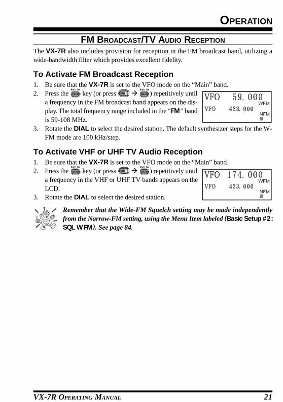
The VX-7R also includes provision for reception in the FM broadcast band, utilizing awide-bandwidth filter which provides excellent fidelity.
To Activate FM Broadcast Reception1. Be sure that the VX-7R is set to the VFO mode on the “Main” band.2. Press the key (or press à ) repetitively until
a frequency in the FM broadcast band appears on the dis-play. The total frequency range included in the “FM” bandis 59-108 MHz.
3. Rotate the DIAL to select the desired station. The default synthesizer steps for the W-FM mode are 100 kHz/step.
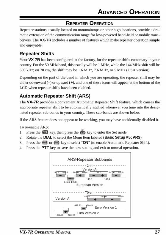
To Activate VHF or UHF TV Audio Reception1. Be sure that the VX-7R is set to the VFO mode on the “Main” band.2. Press the key (or press à ) repetitively until
a frequency in the VHF or UHF TV bands appears on theLCD.
3. Rotate the DIAL to select the desired station.
Remember that the Wide-FM Squelch setting may be made independentlyfrom the Narrow-FM setting, using the Menu Item labeled (Basic Setup #2:SQL WFM). See page 84.

VX-7R OPERATING MANUAL22
WEATHER BROADCAST RECEPTION
The VX-7R includes a unique feature which allows reception of weather broadcasts in the160-MHz frequency range. Ten standard Weather Broadcast channels are pre-loaded intoa special memory bank.
To listen to a Weather Broadcast Channel or VHF Marine Channel:
1. Press the key, then press the key to recall theWeather Broadcast channels.
2. Turn the DIAL knob to select the desired Weather Broad-cast channel.
3. If you wish to check the other channels for activity by scanning, just press the PTTswitch.
4. To exit to normal operation, again the key, then press the key. Operation willreturn to the VFO or Memory channel you were operating on before you began WeatherBroadcast operation.
In the event of extreme weather disturbances, such as storms and hurricanes,the NOAA (National Oceanic and Atmospheric Administration) sends aweather alert accompanied by a 1050 Hz tone and subsequent weather report
on one of the NOAA weather channels. You may disable the Weather Alert tone viaMenu Item (Misc Setup #20 WX ALERT), if desired.
OPERATION

VX-7R OPERATING MANUAL 23
KEYBOARD LOCKING
In order to prevent accidental frequency change or inadvertent transmission, various as-pects of the VX-7R’s keys and switches may be locked out. The possible lockout combina-tions are:
KEY: Just the front panel keys are locked outDIAL: Just the top panel DIAL is locked outKEY+DIAL: Both the DIAL and Keys are locked outPTT: The PTT switch is locked (TX not possible)KEY+PTT: Both the keys and PTT switch are locked outDIAL + PTT:Both the DIAL and PTT switch are locked outALL: All of the above are locked out
To lock out some or all of the keys:1. Press the key, then press the key to enter the Set mode.2. Rotate the DIAL to select the Menu Item labeled (Basic
Setup #10: LOCK MODE).3. Press the or key to choose between one of the
locking schemes as outlined above.4. When you have made your selection, press the PTT switch to save the new setting and
resume normal operation.5. To activate the locking feature, press and hold in the
key for 2 seconds. The “ ” icon will appear on the LCD.To cancel locking, again press and hold the key for2 seconds.
Even when “ALL” keys have been locked out, one key actually is not lockedout: the key remains available so you can unlock your keypad when youwant to!
OPERATION

VX-7R OPERATING MANUAL24
KEYPAD/LCD ILLUMINATION
Your VX-7R includes a reddish illumination lamp which aids in nighttime operation. Thered illumination yields clear viewing of the display in a dark environment, with minimaldegradation of your night vision. Three options for activating the lamp are provided:
KEY Mode: Illuminates the Keypad/LCD for 5 seconds when any key pressed.CONTINUE Mode: Illuminates the Keypad/LCD continuously.OFF Mode: Disables the Keypad/LCD lamp.
Here is the procedure for setting up the Lamp mode:1. Press the key, then press the key to enter the Set mode.2. Rotate the DIAL to select the Menu Item labeled (Display
Setup #5: LAMP MODE).3. Press the or key to select one of the three modes
described above.4. When you have made your choice, press the PTT key to save the new setting and
return to normal operation.
DISABLING THE KEYPAD BEEPER
If the keypad’s Beeper creates an inconvenience (particularly when operating in a quietroom), it may easily be disabled.
1. Press key, then press the key to enter the Set mode.2. Rotate the DIAL to select the Menu Item labeled (Basic Setup #9: KEY BEEP).3. Press the or key to change the setting from ON
to OFF.4. When you have made your selection, press the PTT key
to save the new setting and exit to normal operation.5. If you wish to re-enable the Beeper, just repeat the above procedure, pressing the
or key to select ON in step “3” above.
OPERATION

VX-7R OPERATING MANUAL 25
ADVANCED OPERATION
Now that you’re mastered the basics of VX-7R operation, let’s learn more about some ofthe really neat features.
SETTING THE FREQUENCY DISPLAY IMAGE SIZE
VFO ModeWhen operating in the VFO mode during the “Mono” bandoperation, pressing the key, then pressing the or key, causes the LCD to “toggle” between display of double-size characters and large characters. However, this feature doesnot work during Dual Receive operation, as two frequenciesare displayed in that instance.
Memory ModeWhen operating in the Memory mode (see page 45), pressingthe key, followed by the or key, causes the LCDto “toggle” between display of the current memory’s frequency(in double-size characters) and the current memory’s frequency(in large characters) with its alpha-numeric Tag (small char-acters). This feature likewise does not activate during DualReceive operation.
CHANGING THE CHANNEL STEPS
The VX-7R’s synthesizer provides the option of utilizing channel steps of 5/9/10/12.5/15/20/25/50/100 kHz per step, any number of which may be important to your operatingrequirements. The VX-7R is set up at the factory with different default steps on each oper-ating band which probably are satisfactory for most operation. However, if you need tochange the channel step increments, the procedure to do so is very easy.
1. Press the key, then press the key to enter the Set mode.2. Rotate the DIAL to select the Menu Item labeled (Basic Setup #3: VFO STEP).3. Press the or key to select the new channel step
size.4. Press the PTT key to save the new setting and exit to nor-
mal operation.
9 kHz step is available on the BC band only.

VX-7R OPERATING MANUAL26
ADVANCED OPERATION
CHANGING THE OPERATING MODE
The VX-7R provides for automatic mode changing when the radio is tuned to differentoperating frequencies. However, should an unusual operating situation arise in which youneed to change between the available operating modes (FM-Narrow, FM-Wide, and AM),here is the procedure for doing so:
1. Press the key, then press the key to enter the Set mode.2. Rotate the DIAL to select the Menu Item labeled (Basic
Setup #4: RX MODE).3. Press the or key to select the new channel step
size. The available selections are:AUTO: Automatic mode setting per default values for the selected frequency range..N-FM: Narrow-bandwidth FM (used for voice communication)W-FM: Wide-bandwidth FM (used for high-fidelity broadcasting)AM: Amplitude Modulation
4. Press the PTT key to save the new setting and exit to normal operation.
Unless you have a compelling reason to do so, leave the Automatic ModeSelection feature on so as to save time and trouble when changing bands. Ifyou make a mode change for a particular channel or station, you can always
store that one channel into memory, as the mode setting will be memorized along withthe frequency information.
VX-7R OPERATING MANUAL 27
ADVANCED OPERATION
REPEATER OPERATION
Repeater stations, usually located on mountaintops or other high locations, provide a dra-matic extension of the communication range for low-powered hand-held or mobile trans-ceivers. The VX-7R includes a number of features which make repeater operation simpleand enjoyable.
Repeater ShiftsYour VX-7R has been configured, at the factory, for the repeater shifts customary in yourcountry. For the 50 MHz band, this usually will be 1 MHz, while the 144 MHz shift will be600 kHz; on 70 cm, the shift may be 1.6 MHz, 7.6 MHz, or 5 MHz (USA version).
Depending on the part of the band in which you are operating, the repeater shift may beeither downward (–) or upward (+), and one of these icons will appear at the bottom of theLCD when repeater shifts have been enabled.
Automatic Repeater Shift (ARS)The VX-7R provides a convenient Automatic Repeater Shift feature, which causes theappropriate repeater shift to be automatically applied whenever you tune into the desig-nated repeater sub-bands in your country. These sub-bands are shown below.
If the ARS feature does not appear to be working, you may have accidentally disabled it.
To re-enable ARS:1. Press the key, then press the key to enter the Set mode.2. Rotate the DIAL to select the Menu Item labeled (Basic Setup #5: ARS).3. Press the or key to select “ON” (to enable Automatic Repeater Shift).4. Press the PTT key to save the new setting and exit to normal operation.
European Version
Version A2-m
145.1 145.5
145.6 145.8
146.0 146.4 147.0 147.6 148.0
146.6 147.4
Euro Version 1
Euro Version 2
Version A
70-cm440.0 445.0 450.0
439.45438.20
433.00 433.40
ARS-Repeater Subbands

VX-7R OPERATING MANUAL28
Manual Repeater Shift ActivationIf the ARS feature has been disabled, or if you need to set a repeater shift direction otherthan that established by the ARS, you may set the direction of the repeater shift manually.
To do this:1. Press the key, then press the key to enter the Set mode.2. Rotate the DIAL to select the Menu Item labeled (Basic
Setup #7: RPT SHIFT).3. Press the or key to select the desired shift among
“–RPT,” “+RPT,” and “SIMP.”4. Press the PTT key to save the new setting and exit to normal operation.
Changing the Default Repeater ShiftsIf you travel to a different region, you may need to change the default repeater shift so as toensure compatibility with local operating requirements.
To do this, follow the procedure below:1. Press the key, then press the key to enter the Set mode.2. Rotate the DIAL to select the Menu Item labeled (Basic
Setup #6: SHIFT).3. Press the or key to select the new repeater shift
magnitude.4. Press the PTT key to save the new setting and exit to normal operation.
If you just have one “odd” split that you need to program, don’t change the“default” repeated shifts using this Menu Item! Enter the transmit and re-ceive frequencies separately, as shown on page 46.
REPEATER OPERATION
ADVANCED OPERATION

VX-7R OPERATING MANUAL 29
ADVANCED OPERATION
Checking the Repeater Uplink (Input) FrequencyIt often is helpful to be able to check the uplink (input) frequency of a repeater, to see if thecalling station is within direct (“Simplex”) range.
To do this, just press the key. You’ll notice that the display has shifted to the repeateruplink frequency. Press the key again to cause operation to revert to normal monitor--ing of the repeater downlink (output) frequency.
The configuration of this key may be set either to “RV” (for checking the inutfrequency of a repeater, or “HM” (for instant switching to the “Home” chan-nel for the band you are operating on). To change the configuration of this
key, use Menu Item (Misc. Setup #2 HOM/REV). See page 49.
REPEATER OPERATION

VX-7R OPERATING MANUAL30
CTCSS OPERATION
Many repeater systems require that a very-low-frequency audio tone be superimposed onyour FM carrier in order to activate the repeater. This helps prevent false activation of therepeater by radar or spurious signals from other transmitters. This tone system, called“CTCSS” (Continuous Tone Coded Squelch System), is included in your VX-7R, and isvery easy to activate.
CTCSS setup involves two actions: setting the Tone Frequency and then set-ting of the Tone Mode. These actions are set up by using the key, or MenuItems (TSQ/DCS/DTMF #1: SQL TYPE ) and (TSQ/DCS/DTMF #2: TONE SET).
1. Press the key, then press the key. This provides a “Short-cut” to Menu Item(TSQ/DCS/DTMF #1: SQL TYPE).
2. Press the or key so that “TONE” appears on thedisplay; this activates the CTCSS Encoder, which allowsrepeater access.
You may notice an additional “DCS” icon appearing while you press the or key in this step. We’ll discuss the Digital Code Squelch sys-
tem shortly.3. Pressing the key in step “2” above will occasionally cause “SQL” to appear adja-
cent to the “TONE.” When “TONE SQL” appears, this means that the Tone SQueLchsystem is active, which mutes your VX-7R’s receiver until it receives a call from an-other radio sending out a matching CTCSS tone. This can help keep your radio quietuntil a specific call is received, which may be helpful while operating in congestedareas.
4. When you have made your selection of the CTCSS tonemode, rotate the DIAL one click clockwise to select MenuItem labeled (TSQ/DCS/DTMF #2: TONE SET). This Menuselection allows setting of the CTCSS tone frequency tobe used.
5. Press the key to enable the adjustment of the CTCSS frequency..6. Press the or key until the display indicates the Tone Frequency you need to be
using (ask the repeater owner/operator if you don’t know the tone frequency).7. When you have made your selection, press the key, then press the PTT switch to
save the new settings and exit to normal operation.
Your repeater may or may not re-transmit a CTCSS tone - some systems justuse CTCSS to control access to the repeater, but don’t pass it along whentransmitting. If the S-Meter deflects, but the VX-7R is not passing audio,
repeat steps “1” through “3” above, but rotate the DIAL so that “SQL” disappears - thiswill allow you to hear all traffic on the channel being received.
ADVANCED OPERATION

VX-7R OPERATING MANUAL 31
DCS OPERATION
Another form of tone access control is Digital Code Squelch, or DCS. It is a newer, moreadvanced tone system which generally provides more immunity from false paging thandoes CTCSS. The DCS Encoder/Decoder is built into your VX-7R, and operation is verysimilar to that just described for CTCSS. Your repeater system may be configured forDCS; if not, it is frequently quite useful in Simplex operation if your friend(s) use trans-ceivers equipped with this advanced feature.
Just as in CTCSS operation, DCS requires that you set the Tone Mode to DCSand that you select a tone code.
1. Press the key, then press the key. This provides a “Short-cut” to Menu Item(TSQ/DCS/DTMF #1: SQL TYPE).
2. Press the or key until “DCS” appears on the dis-play; this activates the DCS Encoder/Decoder.
3. Now rotate the DIAL to select Menu Item (TSQ/DCS/DTMF #3: DCS SET).
4. Press the key to enable the adjustment of the DCScode.
5. Press the or key to select the desired DCS Code(a three-digit number). Ask the repeater owner/operator if you don’t know DCS Code;if you are working simplex, just set up the DCS Code to be the same as that used byyour friend(s).
6. When you have made your selection, press the key, then press the PTT switch tosave the new settings and exit to normal operation.
Remember that the DCS is an Encode/Decode system, so your receiver willremain muted until a matching DCS code is received on an incoming trans-mission. Switch the DCS off when you’re just tuning around the band!
ADVANCED OPERATION
CTCSS TONE FREQUENCY (Hz)
67.0 69.3 71.9 74.4 77.0 79.7
82.5 85.4 88.5 91.5 94.8 97.4
100.0 103.5 107.2 110.9 114.8 118.8
123.0 127.3 131.8 136.5 141.3 146.2
151.4 156.7 159.8 162.2 165.5 167.9
171.3 173.8 177.3 179.9 183.5 186.2
189.9 192.8 196.6 199.5 203.5 206.5
210.7 218.1 225.7 229.1 233.6 241.8
250.3 254.1 – – – –
DCS CODE023 025 026 031 032 036 043 047 051 053
054 065 071 072 073 074 114 115 116 122
125 131 132 134 143 145 152 155 156 162
165 172 174 205 212 223 225 226 243 244
245 246 251 252 255 261 263 265 266 271
274 306 311 315 325 331 332 343 346 351
356 364 365 371 411 412 413 423 431 432
445 446 452 454 455 462 464 465 466 503
506 516 523 526 532 546 565 606 612 624
627 631 632 654 662 664 703 712 723 731
732 734 743 754 – – – – – –

VX-7R OPERATING MANUAL32
TONE SEARCH SCANNING
In operating situations where you don’t know the CTCSS or DCS tone being used byanother station or stations, you can command the radio to listen to the incoming signal andscan in search of the tone being used. Two things must be remembered in this regard:
¦ You must be sure that your repeater uses the same tone type (CTCSS vs. DCS).¦ Some repeaters do not pass the CTCSS tone; you may have to listen to the station(s)
transmitting on the repeater uplink (input) frequency in order to allow Tone SearchScanning to work.
To scan for the tone in use:1. Set the radio up for either CTCSS or DCS Decoder operation (see the previous discus-
sion). In the case of CTCSS, “TSQ” will appear on the display; in the case of DCS,“DCS” will appear on the display.
2. Press the key, then press the key to enter the Set mode.3. Rotate the DIAL to select the Menu Item labeled (TSQ/
DCS/DTMF #2: TONE SET) when TONE SQL is selected,or Menu Item labeled (TSQ/DCS/DTMF #3: DCS SET)during DCS operation.
4. Press the key to enable adjustment of the selectedMenu Item.
5. Press the key, then press the key to start scanningfor the incoming CTCSS or DCS tone/code.
6. When the radio detects the correct tone or code, it will halt on that tone/code, andaudio will be allowed to pass. Press the key to lock in that tone/code, then pressPTT to exit to normal operation.
If the Tone Scan feature does not detect a tone or code, it will continue toscan indefinitely. When this happens, it may be that the other station is notsending any tone. You can press the PTT switch to halt the scan at any time.
You also can press the MONI key during Tone Scanning to listen to the (muted) signalfrom the other station. When you release the MONI key, Tone Scanning will resume afterabout a second.
Tone Scanning works either in the VFO or Memory modes.
ADVANCED OPERATION

VX-7R OPERATING MANUAL 33
CTCSS/DCS BELL OPERATION
During CTCSS Decode or DCS operation, you may set up the VX-7R such that a ringing“bell” sound alerts you to the fact that a call is coming in. Here is the procedure for activat-ing the CTCSS/DCS Bell:
1. Set the transceiver up for CTCSS Decode (“Tone Squelch”) or DCS operation, asdescribed previously.
2. Adjust the operating frequency to the desired channel.3. Press the key, then press the key to enter the Set mode.4. Rotate the DIAL to select the Menu Item labeled (TSQ/DCS/DTMF #5: BELL).5. Press the or key to set the desired number of
rings of the Bell. The available choices are 1, 3, 5, or 8rings, CONTINUE (continuous ringing), or OFF.
6. Press the PTT key momentarily to save the new settingand exit to normal operation.
When you are called by a station whose transceiver is sending a CTCSS tone or DCS codewhich matches that set into your Decoder, the Bell will ring in accordance to this program-ming.
SPLIT TONE OPERATION
The VX-7R can be operated in a Split Tone configuration via the Set mode.
1. Press the key, then press the key to enter the Set mode.2. Rotate the DIAL to select the Menu Item labeled (TSQ/DCS/DTMF #6: SPLIT TONE).3. Press the or key to select ON (to enable the Split
Tone feature).4. Press the PTT key momentarily to save the new setting
and exit to normal operation.
When the Split Tone feature is activated, you can see the following additional parametersafter the “DCS” parameter while selecting the Menu Item (TSQ/DCS/DTMF #1: SQL TYPE),:
D CODE: DCS Encode only (“ ” icon will appear while operating)TONE DC: Encodes a CTCSS Tone and Decodes a DCS code
(the “ ” icon will appear during operation)DC TONE: Encodes a DCS code and Decodes a CTCSS Tone
(the “ ” icon will appear during operation)
Select the desired operating mode from the selections shown above.
ADVANCED OPERATION

VX-7R OPERATING MANUAL34
TONE CALLING (1750 HZ)If the repeaters in your country require a 1750-Hz burst tone for access (typically in Eu-rope), you can set the MONI key to serve as a “Tone Call” switch instead. To change theconfiguration of this switch, we again use the Menu to help us.
1. Press the key, then press the key to enter the Set mode.2. Rotate the DIAL to select the Menu Item labeled (Misc Setup #3 MON/T-CAL).3. Press the or key to select “T-CALL” on the dis-
play.4. Press the PTT key to save the new setting and exit to nor-
mal operation.5. To access a repeater, press and hold in the MONI key for the amount of time specified
by the repeater owner/operator. The transmitter will automatically be activated, and a1750-Hz audio tone will be superimposed on the carrier. Once access to the repeaterhas been gained, you may release the MONI key, and use the PTT key for activatingthe transmitter.
ADVANCED OPERATION

VX-7R OPERATING MANUAL 35
ARTS (AUTOMATIC RANGE TRANSPONDER SYSTEM)The ARTS feature uses DCS signaling to inform both parties when you and another ARTS-equipped station are within communications range. This may be particularly useful duringSearch-and Rescue situations, where is important to stay in contact with other members ofyour group.
Both stations must set up their DCS codes to the same code number, then activate theirARTS feature using the command appropriate for their radio. Alert ringers may be acti-vated, if desired.
Whenever you push the PTT, or every 25 (or 15) seconds after ARTS is activated, yourradio will transmit a signal which includes a (subaudible) DCSsignal for about 1 second. If the other radio is in range, thebeeper will sound (if enabled) and the display will show “INRANGE” as opposed to the out of range display “OUT RANGE”in which ARTS operation begins.
Whether you talk or not, the polling every 15 or 25 secondswill continue until you de-activate ARTS. Every 10 minutes,moreover, you can have your radio transmit your callsign viaCW, so as to comply with identification requirements. When ARTS is de-activated, DCSwill also be deactivated (if you were not using it previously in non-ARTS operation).
If you move out of range for more than one minute (four pollings), your radio will sensethat no signal has been received, three beeps will sound, and the display will revert to“OUT RANGE.” If you move back into range, your radio will again beep, and the displaywill change back to the “IN RANGE” indication.
During ARTS operation, your operating frequency will continue to be displayed, but nochanges may be made to it or other settings; you must terminate ARTS in order to resumenormal operation. This is a safety feature designed to prevent accidental loss of contactdue to channel change, etc.
Here is how to activate ARTS:Basic ARTS Setup and Operation1. Set your radio and the other radio(s) to the same DCS code number, per the discussion
on page 31.2. Press the key, then press the key. You will observe the “OUT RANGE” display
on the LCD below the operating frequency. ARTS operation has now commenced.3. Every 25 seconds, your radio will transmit a “polling” call to the other station. When
that station responds with its own ARTS polling signal, the display will change to “INRANGE” to confirm that the other station’s polling code was received in response toyours.
ADVANCED OPERATION

VX-7R OPERATING MANUAL36
4. Press the key, then press the key to exit ARTS operation and resume normalfunctioning of the transceiver.
ARTS won’t work if you have used the Lock feature to disable the PTT!
ARTS Polling Time OptionsThe ARTS feature may be programmed to poll every 25 seconds (default value) or 15seconds. The default value provides maximum battery conservation, because the pollingsignal is sent out less frequently. To change the polling interval:
1. Press the key, then press the key to enter the Set mode.2. Rotate the DIAL to select the Menu Item labeled (ARTS #2: ARTS ITERVAL).3. Press the or key to select the desired polling in-
terval (15 or 25 seconds).4. When you have made your selection, press the PTT key
to save the new setting and exit to normal operation.
ARTS Alert Beep OptionsThe ARTS feature allows two kinds of alert beeps (with the additional option of turningthem off), so as to alert you to the current status of ARTS operation. Depending on yourlocation and the potential annoyance associated with frequent beeps, you may choose theBeep mode which best suits your needs. The choices are:
IN RANGE: The beeps are issued only when the radio first confirms that you are withinrange, but does not re-confirm with beeps thereafter.
ALWAYS: Every time a polling transmission is received from the other station, thealert beeps will be heard.
OFF: No alert beeps will be heard; you must look at the display to confirmcurrent ARTS status.
To set the ARTS Beep mode, use the following procedure:1. Press the key, then press the key to enter the Set mode.2. Rotate the DIAL to select the Menu Item labeled (ARTS #1: ARTS BEEP).3. Press the or key to select the desired ARTS Beep
mode (see above).4. When you have made your selection, press the PTT key
to save the new setting and exit to normal operation.
ADVANCED OPERATION
ARTS (AUTOMATIC RANGE TRANSPONDER SYSTEM)

VX-7R OPERATING MANUAL 37
ADVANCED OPERATION
CW Identifier SetupThe ARTS feature includes a CW identifier, as discussed previously. Every ten minutesduring ARTS operation, the radio can be instructed to send “DE (your callsign) K” if thisfeature is enabled. The callsign field may contain up to 16 characters.
Here’s how to program the CW Identifier:1. Press the key, then press the key to enter the Set mode.2. Rotate the DIAL to select the Menu Item labeled (ARTS
#3: CW ID).3. Press the key to enable changing of this Menu item.
The “ ” indicator will blink on the LCD.4. Press the or key to set the CW ID function to ON.5. Rotate the DIAL one click clockwise to begin entry of the letters and numbers in your
callsign.6. Press the key or keyboard to set the first letter or number in your callsign.
Example 1: Press the key to select any of the 7 available characters (includingthe “slant bar” for portable stations); or
Example 2: Press the key repeatedly to toggle among the seven available charac-ters associated with that key: A à B à C à a à b à c à 2
7. When the correct character has been selected, rotate the DIAL one click clockwise tomove on to the next character.
8. Repeat steps 6 and 7 as many times as necessary to complete your callsign. Note thatthe “slant bar” (– • • – •) is among the available characters, should you be a “portable”station.
9. Press the key to delete all data after the cursor that may have been previouslystored erroneously.
10. When you have entered your entire callsign, press the key to confirm the callsign,then press the PTT key to save the settings and exit to normal operation.
You may check your work by monitoring the entere callsign. To do this, repeatsteps 1 - 3 above, then press the key..
ARTS (AUTOMATIC RANGE TRANSPONDER SYSTEM)

VX-7R OPERATING MANUAL38
DTMF OPERATION
The VX-7R’s 16-button keypad allows easy DTMF dialing for Autopatch, repeater con-trol, or Internet-link access purposes. Besides numerical digits [0] through [9], the keypadincludes the [*] and [#] digits, plus the [A], [B], [C], and [D] tones often used for repeatercontrol.
Manual DTMF Tone GenerationYou can generate DTMF tones during transmission manually.1. Press the PTT switch to begin transmission.2. While transmitting, press the desired numbers on the keypad.3. When you have sent all the digits desired, release the PTT key.
DTMF AutodialerNine DTMF Autodial memories are provided, allowing you to store telephone numbers forautopatch use. You can also store short autopatch or Internet-link access code streams so asto avoid having to send them manually.
Here is the DTMF Autodial storage procedure:1. Press the key, then press the key to enter the Set mode.2. Rotate the DIAL knob to select the Menu Item labeled
(TSQ/DCS/DTMF #8: DTMF SET).3. Press the key to enable adjustment of this Menu Item.4. Press the or key to select the DTMF Memory
register into which you wish to store this DTMF string.5. Rotate the DIAL knob one click to begin DTMF Memory entry into the selected regis-
ter.6. Key in the DTMF digits you wish to store into this register. If needed, you may press
the key to store a “Pause” (rotate the DIAL one click clockwise to continue) orpress the key again to delete the previously-stored data after the cursor..
7. If you make a mistake, rotate the DIAL konb counterclockwise to back-space the cur-sor, re-enter the correct number.
8. Press the PTT switch to save the setting. To store other numbers, repeat this process,using a different DTMF memory register.
ADVANCED OPERATION

VX-7R OPERATING MANUAL 39
To send the telephone number:1. Press the key, then press the key to enter the Set mode.2. Rotate the DIAL to select the Menu Item labeled (TSQ/DCS/DTMF #7: DTMF DI-
ALER).3. Press the or key to set the DTMF Autodialer
function to the “ON” position.4. Press the PTT switch to exit to normal operation and acti-
vate the DTMF Autodialer function (the “ ” icon willappear).
5. In the Autodialer function mode, first press the PTT key,then press the numerical key ( through ) correspond-ing to the DTMF memory string you wish to send. Once the string begins, you mayrelease the PTT key, as the transmitter will be held “on the air” until the DTMF stringis completed.
EMERGENCY CHANNEL OPERATION
The VX-7R includes an “Emergency” feature which may be useful if you have someonemonitoring on the same frequency as your transceiver’s UHF “Home” channel. See page47 for details on setting the Home channel.
The “Emergency” feature is activated by pressing the key for 1/2 seconds.
When this is done, (A) the radio is placed on the UHF amateur band Home channel, (B) itemits a loud “Alarm” sound (the volume is controlled by the VOLUME knob), (C) itflashes the STROBE in sequential colors, (D) if you press the PTT key, you will disablethe Emergency feature temporarily; you can then transmit on the UHF Home channel, and(E) two seconds after the PTT release, the Emergency feature will resume.
To disable the “Emergency” feature, press the key for 1/2 seconds or turn the radio Offfby pressing and holding in the (PWR) switch for 2 seconds.
Use this feature if you are out for a walk and want a quick way of alerting a family memberas to a dangerous situation. The alarm sound may discourage an attacker and allow you toescape.
1) Be sure to arrange with a friend or family member to be monitoring on thesame frequency, as there will be no identification sent via the Emergencyalarm sound. And do not transmit the alarm tone except in a true emergency!
2) The STROBE may be changed to another function via Menu Item (Misc Setup #5:EMG SET); see page 94.
ADVANCED OPERATION
DTMF OPERATION

VX-7R OPERATING MANUAL40
ATT (FRONT END ATTENUATOR)The attenuator will reduce all signals (and noise) by 20 dB, and it may be used to makereception more pleasant under extremely noisy conditions.
1. Press the key, then press the key to enter the Set mode.2. Rotate the DIAL to select the Menu Item labeled (Misc Setup #18: ATT).3. Press the or key to change the setting from OFF
to ON.4. When you have made your selection, press the PTT key
to save the new setting and exit to normal operation.5. If you wish to disable the attenuator, just repeat the above
procedure, pressing the or key to select OFF instep “3” above.
When the attenuator is activated, the “ ” icon willappear on the display.
RECEIVE BATTERY SAVER SETUP
An important feature of the VX-7R is its Receive Battery Saver, which “puts the radio tosleep” for a time interval, periodically “waking it up” to check for activity. If somebody istalking on the channel, the VX-7R will remain in the “active” mode, then resume its “sleep”cycles. This feature significantly reduces quiescent battery drain, and you may change theamount of “sleep” time between activity checks using the Menu System:
1. Press the key, then press the key to enter the Set mode.2. Rotate the DIAL to select the Menu Item labeled (Save Modes #2: RX SAVE).3. Press the or key to select the desired “sleep”
duration. The selections available are 200 ms, 300 ms,500 ms, 1 second, and 2 seconds, or OFF. The defaultvalue is 200 ms.
4. When you have made your selection, press the PTT key to save the new setting andexit to normal operation.
When you are operating on Packet, switch the Receive Battery Saver OFF, asthe sleep cycle may “collide” with the beginning of an incoming Packet trans-mission, causing your TNC not to receive the full data burst.
ADVANCED OPERATION

VX-7R OPERATING MANUAL 41
TX BATTERY SAVER
The VX-7R also includes a useful Transmit Battery Saver, which will automatically lowerthe power output level when the last signal received was very strong. For example, whenyou are in the immediate vicinity of a repeater station, there generally is no reason to usethe full 5 Watts of power output in order to achieve full-quieting access to the repeater.With the Transmit Battery Saver, the automatic selection of Low Power operation con-serves battery drain significantly.
To activate the Transmit Battery Saver:1. Press the key, then press the key to enter the Set mode.2. Rotate the DIAL to select the Menu Item labeled (Save Modes #3: TX SAVE).3. Press the or key to set this Menu Item to “ON”
(thus activating the Transmit Battery Saver).4. When you have completed your selection, press the PTT
key to save the new setting and exit to normal operation.
DISABLING THE “STROBE”Further battery conservation may be accomplished by disabling the “STROBE” whilereceiving a signal (when the “STROBE” functions as a “BUSY” LED). Use the followingprocedure:
1. Press the key, then press the key to enter the Set mode.2. Rotate the DIAL to select the Menu Item labeled (Display Setup #1: BUSY LED).3. Press the or key to set this Menu Item to “OFF”
(thus disabling the BUSY lamp).4. Press the PTT key to save the new setting and exit to nor-
mal operation.
ADVANCED OPERATION

VX-7R OPERATING MANUAL42
AUTOMATIC POWER-OFF (APO) FEATURE
The APO feature helps conserve battery life by automatically turning the radio off after auser-defined period of time within which there has been no dial or key activity.
The available selections for the time before power-off are 0.5/1/3/5/8 hours, as well asAPO Off. The default condition for the APO is OFF, and here is the procedure for activat-ing it:
1. Press the key, then press the key to enter the Set mode.2. Rotate the DIAL to select the Menu Item labeled (Save Modes #1: APO).3. Press the or key to select the desired time period
after which the radio will automatically shut down.4. Once you have made your selection, press the PTT key to
save the new setting and exit to normal operation.
When the APO is activated, the “ ” icon will appear at thecenter bottom on the LCD. If there is no action by you withinthe time interval programmed, the microprocessor will shutdown the radio automatically.
Just press and hold in the (PWR) switch for 2 seconds to turn the transceiver back onafter an APO shutdown, as usual.
TRANSMITTER TIME-OUT TIMER (TOT)The TOT feature provides a safety switch which limits transmission to a pre-programmedvalue. This will promote battery conservation by not allowing you to make excessively-long transmissions, and in the event of a stuck PTT switch (perhaps if the radio or a Speaker/Mic is wedged between car seats) it can prevent interference to other users as well asbattery depletion. As configured at the factory the TOT feature is set to OFF, and here is theprocedure for activating it:
1. Press the key, then press the key to enter the Set mode.2. Rotate the DIAL to select the Menu Item labeled (Save Modes #4: TOT).3. Press the or key to set the Time-Out Timer to the
desired “Maximum TX” time (1 minute, 2.5 minutes, 5minutes, or 10 minutes).
4. Once you’re made the selection you wish to use, press thePTT key to save the new setting and exit to normal operation.
Since brief transmissions are the mark of a good operator, try setting up yourradio’s TOT feature for a maximum transmission time of 1 minute. This willsignificantly improve battery life, too!
ADVANCED OPERATION

VX-7R OPERATING MANUAL 43
ADVANCED OPERATION
BUSY CHANNEL LOCK-OUT (BCLO)The BCLO feature prevents the radio’s transmitter from being activated if a signal strongenough to break through the “noise” squelch is present. On a frequency where stationsusing different CTCSS or DCS codes may be active, BCLO prevents you from disruptingtheir communications accidentally (because your radio may be muted by its own ToneDecoder). The default setting for the BCLO is OFF, and here is how to change that setting:
1. Press the key, then press the key to enter the Set mode.2. Rotate the DIAL to select the Menu Item labeled (Misc Setup #1: BCLO).3. Press the or key to set this Menu Item to “ON”
(thus activating the BCLO feature).4. Press the PTT key to save the new setting and resume
normal operation.
MIC MONITOR
The MIC Monitor feature allows you to monitor your voice signal when using the optionalVC-27 Earpiece/Microphone.
1. Connect the VC-27 Earpiece/Microphone to the MIC/SP jack.2. Press the key, then press the key to enter the Set mode.3. Rotate the DIAL to select the Menu Item labeled (Misc Setup #19: MIC MONITOR).4. Press the or key to set this Menu Item to “ON”
(thus activating the MIC Monitor feature). The VX-7Rexit from the Set mode.
5. The VX-7R’s internal microphone will now pick up thesound around the transceiver, then output its to the VC-27 Earpiece/Microphone.
6. To disable the MIC Monitor feature, repeat steps 2 - 4, pressing the or key toselect “OFF,” then press the PTT key.
When this feature is activated without the VC-27 Earpiece/Microphone con-nected, the VX-7R will develop a howling “feedback” condition.

VX-7R OPERATING MANUAL44
CHANGING THE TX DEVIATION LEVEL
In many areas of the world, channel congestion has required that operating channels beclosely spaced. In such operating environments, it often is required that operators usereduced deviation levels, so as to reduce the potential for interference to users on adjacentchannels. The VX-7R includes a simple method of accomplishing this:
1. Press the key, then press the key to enter the Set mode.2. Rotate the DIAL to select the Menu Item labeled (Misc Setup #6: HALF DEVIATION).3. Press the or key to change this setting to ON. In
this configuration (HALF DEVIATION active), thetransmitter’s deviation will be approximately ±2.5 kHz.
4. When you have made your selection, press the PTT keyto save the new setting and exit to normal operation.
The “normal” setting for the deviation (when this Menu Item is set to OFF) is±5 kHz.
ADVANCED OPERATION

VX-7R OPERATING MANUAL 45
MEMORY MODE
The VX-7R provides a wide variety of memory system resources. These include:
r Regular Memory Channels, which made up of:¦ 450 “Standard” memory channels, numbered “1” through “450.”¦ 12 (USA version) or 11 (EXP version) Home channels, providing storage and
quick recall of one prime frequency on each operating band.¦ 20 sets of band-edge memories also known as “Programmable Memory Scan”
channels, labeled “L1/U1” through “L20/U20.”¦ Nine Memory Groups, labeled “MG1” through “MG9.” Each Memory Group can
be assigned 48 channels from the “standard” memory channel bank.r Ten One-Touch Memory Channelsr Ten “Hyper-Memory” Channelsr Ten “Weather Broadcast” Channlesr 89 popular Short-wave Broadcast Station Memory Channels.r 280 VHF Marine Channels.
430
MH
z B
and
222
MH
z B
and
144
MH
z B
and
50 M
Hz
Ban
dA
ctio
n B
and-
2U
HF-
TV B
and
Act
ion
Ban
d-1
VH
F-TV
Ban
dA
IR B
and
FM
BC
Ban
dS
W B
and
BC
Ban
d
HOME Channels(USA: 12 channels, EXP: 11 channels)
Marine Channels(280 channels)
Short-wave Broadcast Station Memory Channels(89 channels)
MR
450
MR
449
MR
4M
R3
MR
2M
R1
OTM
3O
TM
2O
TM1
OTM
0
OT
M9
OT
M8
L20/
U20
L19/
U19
L4/U
4L3
/U3
L2/U
2L1
/U1
Standard Memory Channels(450 channels)
One-Touch Memory Channels(10 channels)
PMS Memory Channels(20 Sets)
Hyper Memory Channels(10 channels)
HY
P0
HY
P1
HY
P2H
YP
3 HY
P8
HY
P9
Weather Broadcast Channels(10 channels)
WX
10W
X9
WX
4W
X3
WX2
WX
1
222 MHz Band:USA version only

VX-7R OPERATING MANUAL46
MEMORY MODE
REGULAR MEMORY CHANNEL OPERATION
Memory Storage1. Select the desired frequency, while operating in the VFO mode. Be sure to set up any
desired CTCSS or DCS tones, as well as any desired repeater offset. The power levelmay also be set at this time, if you wish to store it.
2. Press and hold in the key for 1/2 second.3. Within five seconds of releasing the key, rotate the DIAL to select the desired
memory channel. The microprocessor will automatically select the next-available “free”channel (a memory register on which no data has beenstored). If you see an Asterisk (Û) by any channel num-ber, it means that the channel currently has no data writtenon it (i.e. the channel is “free”.)
4. Press the key once more to store the frequency into memory..5. You still will be operating in the “VFO” mode, so you may now enter other frequen-
cies, and store them into additional memory locations, by repeating the above process.
You may change the automatic memory channel selection feature to selectthe “next-highest memory channel above the last-stored memory channel”by instead of the “next-available ‘free’ channel” via the Menu Item labeled
(Basic Setup #12 MW MODE); see page 85.
Storing Independent Transmit Frequencies (“Odd Splits”)All memories can store an independent transmit frequency, for operation on repeaters withnon-standard shift. To do this:
1. Store the receive frequency using the method already described under MEMORYSTORAGE (it doesn’t matter if a repeater offset is active).
2. Turn to the desired transmit frequency, then press and hold in the key for 1/2second.
3. Within five seconds of releasing the key, rotate the DIAL to select the same memorychannel number as used in step “1” above.
4. Press and hold in the PTT switch, then press the key once more momentarilywhile holding the PTT switch in (this does not key the transmitter).
Whenever you recall a memory which contains independently-stored transmitand receive frequencies, the “ ” indication will appear in the display..

VX-7R OPERATING MANUAL 47
MEMORY MODE
REGULAR MEMORY CHANNEL OPERATION
Memory Recall1. While operating in the VFO mode, press the key to
enter the Memory mode.2. Rotate the DIAL to select the desired channel.3. To return to the VFO mode, press the key..
1) When the radio is already set to the Memory mode, an easy way to recallmemories is to key in the memory channel number, then press the key..For example, to recall memory channel #14, press à à .
2) Memory channels on which you may have stored frequencies outside the amateurbands cannot be recalled on the SUB band.
HOME Channel MemoryA special one-touch “HOME” channel is available (one foreach of the 12 (USA version) or 11 (EXP version) operatingbands: see page 15), to allow quick recall of a favorite operat-ing frequency on each band. Memory storage is simple to ac-complish:
1. Select the desired frequency, while operating in the VFO mode. Be sure to set up anydesired CTCSS or DCS tones, as well as any desired repeater offset. The power levelmay also be set at this time, if you wish to store it.
2. Press and hold in the key for 1/2 second.3. While the memory channel number is blinking, just press the key. The frequency
and other data (if any) will now be stored in the special HOME channel register.4. You may repeat this process on the other operating bands.5. To recall the HOME channel, press the key, then press the key while operat-
ing either in the VFO or MR mode.
Note that the UHF HOME channel is the one used during “Emergency” opera-tion. See page 39 for details regarding this feature.

VX-7R OPERATING MANUAL48
Labeling MemoriesYou may wish to append an alpha-numeric “Tag” (label) to a memory or memories, to aidin recollection of the channel’s use (such as a club name, etc.). This is easily accomplishedusing the Set mode.
1. Recall the memory channel on which you wish to append a label.2. Press the key, then press the key to enter the Set mode.3. Rotate the DIAL to select the Menu Item labeled (Basic Setup #11: NAME SET).4. Press the key momentarily to enable programming of
the name tag.5. Press the / key, or one of the keyboard keys, to
select the first digit of the desired label.Example 1: Press the key, then press the or key to select any of the 61
available characters.Example 2: Press the key repeatedly to toggle among the seven available charac-
ters associated with that key: A à B à C à a à b à c à 26. Rotate the DIAL one click clockwise to move to the next character.7. Repeat steps 4 and 5 to program the remaining letters,
numbers, or symbols of the desired label. A total of eightcharacters may be used in the creation of a label.
8. When you have completed the creation of the label, pressthe PTT key to save the label and exit.
During “MR” (Memory Recall) operation, the al-phanumeric Tag will appear below the frequencydisplay. The alphanumeric Tag does not appear if
you activate the Dual Receive Operation.
MEMORY MODE
REGULAR MEMORY CHANNEL OPERATION

VX-7R OPERATING MANUAL 49
Memory Offset TuningOnce you have recalled a particular memory channel, you may easily tune off that channel,as though you were in the “VFO” mode.
1. With the VX-7R in the “MR” (Memory Recall) mode, select the desired memory chan-nel.
2. Now press and hold in the key for 1/2 second. The “MR” indicator will be re-placed by one which says “MT” (“Memory Tuning”).
3. Rotate the DIAL, as desired, to tune to a new frequency.The synthesizer steps selected for VFO operation on thecurrent band will be the steps used during Memory Tun-ing.
4. If you wish to return to the original memory frequency, press and hold in the keyfor 1/2 second. The “MT” indicator will be replaced by “MR.”
5. If you wish to store a new frequency set during Memory Tuning, just press and hold inthe key for 1/2 second, per normal memory storage procedure. The microproces-sor will automatically set itself to the next-available clear memory location, and youthen press again to lock in the new frequency..
If you want to replace the original memory contents with those of the newfrequency, be sure to rotate the DIAL to the original memory channel num-ber!
Any required CTCSS/DCS changes, or repeater offset modifications, must be done beforestoring the data into the new (or original) memory channel location.
MEMORY MODE
REGULAR MEMORY CHANNEL OPERATION

VX-7R OPERATING MANUAL50
MEMORY MODE
REGULAR MEMORY CHANNEL OPERATION
Masking MemoriesThere may be situations where you want to “Mask” memories so they are not visible duringmemory selection or scanning. For example, several memories used only in a city you visitinfrequently may be stored, then “Masked” until you visit that city, at which time you can“Unmask” them for normal use.
1. Press the key, if needed, to enter the MR mode.2. Press and hold in the key for 1/2 second, then rotate the DIAL to select the memory
channel to be “Masked” from view.3. Press the key. The display will revert to memory channel #1. If you rotate the
DIAL to the location you just “Masked,” you will observe that it is now invisible.4. To Unmask the hidden memory, repeat the above procedure: press and hold in the
key for 1/2 second, rotate the DIAL to select the masked memory’s umber, then press to restore the memory channel’s data.
Watch out! You can manually store data over a “Masked” memory, deletingprevious data, if you’re not careful. Use the “next available memory” tech-nique (look for the [Û] icon) storage technique to avoid over-writing a masked
memory.

VX-7R OPERATING MANUAL 51
MEMORY MODE
REGULAR MEMORY CHANNEL OPERATION
Memory Group OperationMemory Group Assignment1. Recall the memory channel to be assigned to a Memory Group.2. Press and hold in the key for 1/2 seconds, then press the numbered key ( ~ )
you want as the Memory Group for this channel.3. Now memory channel data is copied into the Memory Group.
Memory Group Recall1. Set the radio to the Memory mode on the “Main” Band by pressing the key, if
necessary.2. Press the key, then press the key to recall the
Special Memory Menu.3. Rotate the DIAL knob to select the “2 MR Group” mode.4. Press the PTT switch to activate the “Memory Group” mode.5. Rotate the DIAL knob to select the desired Memory Group
(“MG1” ~ “MG9”).6. Press the key momentarily to lock in the selected
Memory Group.7. In the Memory Group mode of operation, you can only select memory channels in the
current memory group (up to 48 channels).8. To change the Memory Group to another Group, press the key momentarily, then
rotate the DIAL knob.9. To exit from Memory Group operation, recall the Special Memory Menu (press +
) then change its setting to “1 OFF.”

VX-7R OPERATING MANUAL52
Moving Memory Data to the VFOData stored on memory channels can easily be moved to VFO, if you like.
1. Select the memory channel containing the frequency data to be moved to VFO.2. Press and hold in the key for 1/2 second, then press the key. The data will
now have been copied to VFO, although the original memory contents will remainintact on the previously-stored channel.
If a Split Frequency Memory channel was transferred, the Tx frequency will beignored (you will be set up for Simplex operation on the Receive frequency).
Memory Only ModeOnce memory channel programming has been completed, you may place the radio in a“Memory Only” mode, whereby VFO operation is impossible. This may be particularlyuseful during public-service events where a number of operators may be using the radio forfirst time, and ultimate simplicity of channel selection is desired.
To place the radio into the Memory Only mode, turn the radio off. Now press and hold inthe key while turning the radio on.
To return to normal operation, repeat the above power-on procedure.
MEMORY MODE

VX-7R OPERATING MANUAL 53
HYPER MEMORY MODE
The VX-7R usually stores, into memory, the operating frequency and some aspects ofoperating status (such as CTCSS/DCS data, repeater shift, power level etc.). However, the“Hyper Memory” Mode allows you to store the total current configuration of the radio intoa special “Hyper” memory bank.
For example, a Hyper Memory location may store the frequencies of both the “Main” and“Sub” bands, plus Spectrum Scope operational status, Scanning features, etc.
Hyper Memory Storage1. Set up the transceiver according to the desired configuration, including parameters
such as Spectrum Scope operation, PMS scanning, etc.2. Press and hold in the numeric key ( through ), corresponding to the Hyper
Memory channel into which you wish to store this configuration, for 2 seconds.
In order to prevent accidental storage, the Hyper Memory Storage feature maybe locked out via Menu Item (Basic Setup #14 HYPER WRITE ).
Hyper Memory Recall1. Press the key, then press the key, to recall the Special Memory Menu.2. Rotate the DIAL konb to select the “4 HYP” mode.3. Press the PTT switch to activate the “Hyper Memory”
mode.4. Press the appropriate numeric key ( through ) to
recall the desired Hyper Memory channel.5. To exit the Hyper Memory mode, recall the Special
Memory Menu (press + ), then change its settingto “1 OFF.”
MEMORY MODE

VX-7R OPERATING MANUAL54
ONE-TOUCH MEMORY MODE
The One-Touch feature allows you to recall up to ten favorite frequencies directly via thenumeric ( through ) keys.
One-Touch Memory Storage1. Select the desired frequency, while operating in the VFO mode. Be sure to set up any
desired CTCSS or DCS tones, as well as any desired repeater offset. The power levelmay also be set at this time, if you wish to store it.
2. Press and hold in the key for 1/2 second.3. Within five seconds of releasing the key, rotate the
DIAL to select the desired One-Touch Memory channel,which will be labeled “OTM0” through “OTM9.”
4. Press the key once more to store the frequency intothe selected One-Touch Memory.
5. You still will be operating in the “VFO” mode, so you may now enter other frequen-cies, and store them into additional One-Touch Memory locations, by repeating theabove process.
One-Touch Memory Recall1. Set the VX-7R to Mono band operation on the “Main” band.2. Press the key, then press the key to recall the Special Memory Menu.3. Rotate the DIAL knob to select the “3 OTM” mode.4. Press the PTT switch to activate the “One-Touch Memory”
mode.5. Press the numeric key ( through ) corresponding to
the One-Touch memory you wish to recall.6. To exit the One-Touch Memory mode, recall the Special
Memory Menu (press + ), then change its settingto “1 OFF.”
MEMORY MODE

VX-7R OPERATING MANUAL 55
SHORT-WAVE BROADCAST STATION MEMORY CHANNELS
The Short-wave Broadcast Station Memory Channel Bank has been pre-programmed atthe factory, for quick selection of broadcast stations.
1. Set the VX-7R to Mono band operation on the “Main” band.2. Press the key, then press the key, to recall the
Special Memory Menu.3. Rotate the DIAL knob to select the “5 BC Station” mode.4. Press the PTT switch to activate the “BC Station” mode.5. Rotate the DIAL to select any of the 89 available Broad-
cast Stations.6. To exit the BC Station mode, recall the Special Memory
Menu (press + ), then change its setting to “1OFF.”
MEMORY MODE
LSTNo.123456789
1011121314151617181920212223242526272829303132333435363738394041424344
Freq.(MHz)6.0306.1609.760
11.9305.9957.2359.735
11.7056.1959.410
12.09515.3106.0459.790
11.67015.5253.9556.0759.5459.7356.0607.1759.515
17.7103.9856.1659.885
15.2205.9859.925
11.78013.7405.9556.0209.895
11.6559.5909.985
13.80015.7359.780
11.96015.55521.655
MODE
AMAMAMAMAMAMAMAMAMAMAMAMAMAMAMAMAMAMAMAMAMAMAMAMAMAMAMAMAMAMAMAMAMAMAMAMAMAMAMAMAMAMAMAM
Tag
VOAVOAVOAVOA
CanadaCanadaCanadaCanada
BBCBBCBBCBBC
FranceFranceFranceFrance
DWDWDWDWItalyItalyItalyItaly
SwissSwissSwissSwiss
BelgiumBelgiumBelgiumBelgiumHollandHollandHollandHolland
DenmarkDenmarkDenmarkDenmarkPortugalPortugalPortugalPortugal
Station Name
Voice of AmericaVoice of AmericaVoice of AmericaVoice of AmericaRadio Canada InternationalRadio Canada InternationalRadio Canada InternationalRadio Canada InternationalBritish Broadcasting CorporationBritish Broadcasting CorporationBritish Broadcasting CorporationBritish Broadcasting CorporationRadio France InternationalRadio France InternationalRadio France InternationalRadio France InternationalDeutsche WelleDeutsche WelleDeutsche WelleDeutsche WelleItalian Radio InternationalItalian Radio InternationalItalian Radio InternationalItalian Radio InternationalSwiss Radio InternationalSwiss Radio InternationalSwiss Radio InternationalSwiss Radio InternationalRadio Vlaanderen InternationalRadio Vlaanderen InternationalRadio Vlaanderen InternationalRadio Vlaanderen InternationalRadio NederlandRadio NederlandRadio NederlandRadio NederlandRadio DenmarkRadio DenmarkRadio DenmarkRadio DenmarkRadio PortugalRadio PortugalRadio PortugalRadio Portugal
LSTNo.454647484950515253545556575859606162636465666768697071727374757677787980818283848586878889
MODE
AMAMAMAMAMAMAMAMAMAMAMAMAMAMAMAMAMAMAMAMAMAMAMAMAMAMAMAMAMAMAMAMAMAMAMAMAMAMAMAMAMAMAMAM AM
Freq.(MHz)7.2709.520
11.92015.5856.0907.4859.5909.985
13.8006.0659.490
13.62517.5056.1209.630
11.7559.7955.9405.9207.205
12.0309.435
11.58515.61517.5456.0459.595
11.62015.0207.1905.2509.855
11.6855.9757.2759.570
13.6706.1557.2009.750
11.8505.9959.5809.660
12080
Tag
SpainSpainSpainSpain
LuxembrgNorwayNorwayNorwayNorwaySwedenSwedenSwedenSwedenFinlandFinlandFinlandFinlandRussiaRussiaRussiaRussiaIsraelIsraelIsraelIsraelIndiaIndiaIndiaIndiaChinaChinaChinaChinaKoreaKoreaKoreaKoreaJapanJapanJapanJapan
AustraliAustraliAustraliAustrali
Station Name
Radio Exterior de EspanaRadio Exterior de EspanaRadio Exterior de EspanaRadio Exterior de EspanaRadio LuxembourgRadio Norway InternationalRadio Norway InternationalRadio Norway InternationalRadio Norway InternationalRadio SwedenRadio SwedenRadio SwedenRadio SwedenRadio FinlandRadio FinlandRadio FinlandRadio FinlandVoice of RussiaVoice of RussiaVoice of RussiaVoice of RussiaIsrael Broadcasting AuthorityIsrael Broadcasting AuthorityIsrael Broadcasting AuthorityIsrael Broadcasting AuthorityAll India Radio (AIR)All India Radio (AIR)All India Radio (AIR)All India Radio (AIR)China Radio International (CRI)China Radio International (CRI)China Radio International (CRI)China Radio International (CRI)Radio KoreaRadio KoreaRadio KoreaRadio KoreaRadio JapanRadio JapanRadio JapanRadio JapanRadio AustraliaRadio AustraliaRadio AustraliaRadio Australia
BROADCAST STATION FREQUENCY LIST

VX-7R OPERATING MANUAL56
VHF MARINE MEMORY CHANNELS
The VHF Marine Channel Bank has been pre-programmed at the factory, for quick selec-tion.
1. Set the VX-7R to Mono band operation on the “Main” band.2. Press the key, then press the key, to recall the
Special Memory Menu.3. Rotate the DIAL knob to select the “6 Marine” mode.4. Press the PTT switch to activate the “VHF Marine Chan-
nel” mode.5. Rotate the DIAL to select any of the 280 available VHF
Marine Channels.6. To exit the VHF Marine Channel mode, recall the Special
Memory Menu (press + ), then change its setting to “1OFF.”
MEMORY MODE
VHF MARINE CHANNEL FREQUENCY LIST
Frequency(MHz)
156.000156.050156.100156.150156.200156.250156.300156.350156.400156.450156.500156.550156.600156.650156.700156.750156.800156.850156.900156.950157.000157.050157.100157.150157.200157.250157.300157.350157.400157.450157.500157.550157.600157.650157.700157.750157.800157.850157.900157.950158.000
CHNo.0123456789
10111213141516171819202122232425262728293031323334353637383940
CHNo.414243444546474849505152535455565758596061626364656667686970717273747576777879 8081
Frequency(MHz)
158.050158.100158.150158.200158.250158.300158.350158.400158.450158.500158.550158.600158.650158.700158.750158.800158.850158.900158.950156.025156.075156.125156.175156.225156.275156.325156.375156.425156.475156.525156.575156.625156.675156.725
––
156.875156.925156.975157.025157.075
CHNo.123124125126127128129130131132133134135136137138139140141142143144145146147148149150151152153154155156157158159160161162163
Frequency(MHz)
159.075159.100159.125159.150159.175159.200159.225159.250159.275159.300159.325159.350159.375159.400159.425159.450159.475159.500159.525159.550159.575159.600159.625159.650159.675159.700159.725159.750159.775159.800159.825159.850159.875159.900159.925159.950159.975160.000160.025160.050160.075
CHNo.164165166167168169170171172173174175176177178179180181182183184185186187188189190191192193194195196197198199200201202203204
Frequency(MHz)
160.100160.125160.150160.175160.200160.225160.250160.275160.300160.325160.350160.375160.400160.425160.450160.475160.500160.525160.550160.575160.600160.625160.650160.675160.700160.725160.750160.775160.800160.825160.850160.875160.900160.925160.950160.975161.000161.025161.050161.075161.100
CHNo.246247248249250251252253254255256257258259260261262263264265266267268269270271272273274275276277278279280281
Frequency(MHz)
155.875155.850155.825155.800155.775155.750155.725155.700155.675155.650155.625155.600155.575155.550155.525155.500155.475155.450155.425155.400155.375155.350155.325155.300155.275155.250155.225155.200155.175155.150155.125155.100155.075155.050155.025155.000
Frequency(MHz)
157.125157.175157.225157.275157.325157.375157.425157.475157.525157.575157.625157.675157.725157.775157.825157.875157.925157.975158.025158.075158.125158.175158.225158.275158.325158.375158.425158.475158.525158.575158.625158.675158.725158.775158.825158.875158.925158.975159.000159.025159.050
CHNo.205206207208209210211212213214215216217218219220221222223224225226227228229230231232233234235236237238239240241212243244245
Frequency(MHz)
161.125161.150161.175161.200161.225161.250161.275161.300161.325161.350161.375161.400161.425161.450161.475161.500161.525161.550161.575161.600161.625161.650161.675161.700161.725161.750161.775161.800161.825161.850161.875161.900161.925161.950161.975162.000162.025155.975155.950155.925155.900
CHNo.828384858687888990919293949596979899
100101102103104105106107108109110111112113114115116117118119120121122

VX-7R OPERATING MANUAL 57
The VX-7R allows you to scan just the memory channels, the entire operating band, or aportion of that band. It will halt on signals encountered, so you can talk to the station(s) onthat frequency, if you like.
Scanning operation is basically the same in each of the above modes. Before you begin,take a moment to select the way in which you would like the scanner to resume scanningafter it halts on a signal.
Setting the Scan-Resume TechniqueThree options for the Scan-Resume mode are available:3 SEC/5 SEC/10 SEC: In this mode, the scanner will halt on a signal it encounters, and
will hold there for the selected resume time. If you do not takeaction to disable the scanner within that time period, the scannerwill resume even if the stations are still active.
BUSY: In this mode, the scanner will halt on a signal it encounters. Twoseconds after the carrier has dropped because the other station(s)ceased transmission, the scanner will resume. In the case of con-stant-carrier signals like Weather Station broadcasts, the scannerwill likely remain on this frequency indefinitely.
HOLD: In this mode, the scanner will halt on a signal it encounters. It willnot restart automatically; you must manually re-initiate scanningif you wish to resume.
To set the Scan-Resume mode:1. Press the key, then press the key to enter the Set mode.2. Rotate the DIAL to select the Menu Item labeled (Scan Modes #3: RESUME).3. Press the or key to select the desired scan-re-
sume mode.4. When you have made your selection, press the PTT key
to save the new setting and exit to normal operation.
The default condition for this Menu Item is “5 SEC.”
Setting the Squelch Level during active Scanning operationThe VX-7R allows adjustment of the Squelch level “on the fly” while you are scanning.
1. While the scanner is engaged, press the key, then press the key (the currentsquelch level will appear below the frequency display).
2. Rotate the DIAL to select the desired Squelch level.3. Press the PTT switch momentarily to save the new setting
and exit to normal operation. In this case, pressing thePTT switch this one time will not causing scanning to stop.
SCANNING

VX-7R OPERATING MANUAL58
SCANNING
VFO SCANNING
This mode allows you to scan the entire current operating band.
1. Select the VFO mode by pressing the key, if necessary..2. Press the key, then press the key to start scanning.3. If and when the scanner encounters a signal strong enough to open the squelch, the
scanner will halt temporarily; the decimal point of the frequency display will blinkduring this “Pause” condition.
4. The scanner will then resume according to the Scan-Resume mode selected in theprevious section.
5. To cancel scanning, press the PTT or key..
When you start scanning, the VX-7R will be changing frequency in the up-ward direction. If you want to change direction of the scan while it is under-way, rotate the DIAL one click in the opposite direction (in this case, one click
counter-clockwise). You’ll see the scanner turn around and change frequency down-ward!
You may change the scanning operation so that the VFO frequency will jump to the lowband edge of the next band when the VFO frequency reaches the high edge of the currentband (or vice versa). See page 95 regarding Menu Item (Misc Setup #10 VFO MODE).
MEMORY SCANNING
Memory scanning is similarly easy to initiate:
1. Set the radio to the Memory mode by pressing the key, if necessary..2. Press the key, then press the key to initiate scanning.3. As with VFO scanning, the scanner will halt on any signal encountered that is strong
enough to open the squelch; it will then resume scanning according to the Scan-Re-sume mode set previously.
4. To cancel scanning, press the PTT or key..
On the “Sub” band, Memory Channel scan will search through only the memorychannels which are stored inside the amateur bands.

VX-7R OPERATING MANUAL 59
Temporary Memory SkipIf the scanner repeatedly stops on a channel due to temporary noise or interference, youcan temporarily mark it to be skipped (except for Memory Channel “1”). The channel willbe skipped until you manually stop the scan (by pressing the PTT switch, for example).
To skip a channel temporarily, press the key, then press the key while the scannerhas stopped on the channel to be skipped. The scanner will instantaneously resume, andthat channel will not be scanned during this scanning session.
How to Skip (Omit) a Channel During Memory Scan OperationAs mentioned previously, some continuous-carrier stations like a Weather Broadcast sta-tion will seriously impede scanner operation if you are using the “Carrier Drop” Scan-Resume mode, as the incoming signal will not pause long enough for the transceiver toresume scanning. Such channels may be “Skipped” during scanning, if you like:
1. Set the radio to the Memory Mode by pressing the key, if necessary..2. Rotate the DIAL to select the Memory Channel to be skipped during scanning.3. Press the key, then press the key to enter the Set mode.4. Rotate the DIAL to select the Menu Item labeled (Basic
Setup #13: MEMO SCAN MODE).5. Press the or key so as to select “SKIP.” The cur--
rent Memory Channel will now be ignored during scan-ning. The “PREFERENTIAL” selection is used for “Preferential Memory Scan,” de-scribed in the next column.
6. When you have made your selection, press the PTT key to save the settings and exit tonormal operation.
A small “t” icon will appear when you recall the “skipped”memory channel manually.
To re-institute a channel into the scanning loop, select “OFF”in step 5 above (the “Skipped” channel will, of course, still beaccessible via manual channel selection methods using the DIAL in the MR mode, whetheror not it is locked out of the scanning loop).
MEMORY SCANNING
SCANNING

VX-7R OPERATING MANUAL60
SCANNING
Preferential Memory ScanThe VX-7R also allows you to set up a “Preferential Scan List” of channels which you can“flag” within the memory system. These channels are designated by a “ ” icon when youhave selected them, one by one, for the Preferential Scan List. When you initiate memoryscanning on a channel with the “ ” icon appended, only those channels bearing the “ ”icon will be scanned. If you initiate scanning on a channel which does not have the “ ”icon appended, you will scan all channels including those with the “ ” icon appended.
1) Here is the procedure for setting up and using the Preferential Scan List:1. Press the key momentarily to enter the Memory Recall mode, if you are not using
memories already.2. Rotate the DIAL to select the channel which you wish to add to the Preferential Scan
List.3. Press the key, then press the key to enter the Set mode.4. Rotate the DIAL to select the Menu Item labeled (Basic Setup #13: MEMO SCAN
MODE).5. Press the or key so as to select “PREFERENTIAL.”6. When you have made your selection, press the PTT key to
save the settings and exit to normal operation.
2) To initiate Preferential Memory Scan:1. Press the key momentarily to enter the Memory Recall mode, if you are not using
memories already.2. Rotate the DIAL to select any channel which has an “ ”
icon appended to the channel number.3. Press the key, then press the key to initiate Pref-
erential Memory Scanning. Only the channels which havean “ ” icon appended to the channel number will be scanned.
MEMORY SCANNING

VX-7R OPERATING MANUAL 61
PROGRAMMABLE (BAND LIMIT) MEMORY SCAN (PMS)This feature allows you to set sub-band limits for either scanning or manual VFO opera-tion. For example, you might with to set up a limit (in North America) of 144.300 MHz to148.000 MHz so as to prevent encroachment into the SSB/CW “Weak Signal” portion ofthe band below 144.300 MHz. Here’s how to do this:
1. Set the radio to the VFO mode by pressing the key, if necessary..2. Using the techniques learned earlier, store (per the above
concept) 144.300 MHz into Memory Channel #L1 (the“L” designates the Lower sub-band limit).
3. Likewise, store 148.000 MHz into Memory Channel #U1(the “U” designates the Upper sub-band limit).
4. Switch to the Memory mode by pressing the key once, then rotate the DIAL toselect Memory Channel # L1.
5. Press and hold in the key for 1/2 second to start PMSoperation; the “MR” label will be replaced by “PMS” inthe upper left-hand corner of the display. Tuning and can-ning will now be limited within the just-programmed range.
6. 20 pairs of Band Limit memories, labeled L1/U1 through L20/U20 are available. Youtherefore can set upper and lower operation limits on a number of bands, if you like.
“PRIORITY CHANNEL” SCANNING (DUAL WATCH)The VX-7R’s scanning features include a two-channel scanning capability which allowsyou to operate on a VFO or Memory channel, while periodically checking a user-definedMemory Channel for activity. If a station is received on the Memory Channel which isstrong enough to open the Squelch, the scanner will pause on that station in accordancewith the Scan-Resume mode set via Menu Item (Scan Modes #3: RESUME). See page 56.
Here is the procedure for activating Priority Channel Dual Watch operation:1. Press the key momentarily to enter the Memory Recall mode, if you are not using
memories already.2. Press and hold in the key for 1/2 second, then select the memory channel you
wish to be the “Priority” channel.3. Press the key. When rotate the DIAL to select the “Priority” channel, a “P” icon
(for the “Main” band priority channel) or “p” icon (for the “Sub” band priority chan-nel) will appear to the right of the “MR” icon, indicating it is the Priority channel.
3. Now set the VX-7R for operation on another memory channel, or on a VFO frequency.4. Press the key, then press the key. The display will
remain on the VFO or memory channel selected, but ev-ery five seconds the VX-7R will check the Priority Chan-nel for activity.
SCANNING

VX-7R OPERATING MANUAL62
AUTOMATIC LAMP ILLUMINATION ON SCAN STOP
The VX-7R will automatically illuminate the LCD Lamp whenever the scanner stops on asignal; this allows you to see the frequency of the incoming signal better at night. Note thatthis will, of course, increase the battery consumption, so be sure to switch it off during theday (the default condition for this feature is “ON”).
The procedure for disabling the Scan Lamp is:
1. Press the key, then press the key to enter the Set mode.2. Rotate the DIAL to select the Menu Item labeled (Scan
Modes #4: SCAN LAMP).3. Press the or key to set this Menu Item to OFF.4. When you have made your selection, press the PTT to
save the new setting and exit to normal operation.
BAND EDGE BEEPER
The VX-7R will automatically “beep” when a band edge is encountered during scanning(either in standard VFO scanning or during PMS operation). You may enable this feater(band edge beeper) when the frequency reaches the band edge while selecting the VFOfrequency by the DIAL.
The procedure for disabling the Band-Edge Beeper is:
1. Press the key, then press the key to enter the Set mode.2. Rotate the DIAL to select the Menu Item labeled (Scan
Modes #2: EDGE BEEP).3. Press the or key to set this Menu Item to ON.4. When you have made your selection, press the PTT to
save the new setting and exit to normal operation.
SCANNING

VX-7R OPERATING MANUAL 63
The Spectrum Analyzer allows viewing operating activity on channels above or below thecurrent operating channel in the VFO mode.
The display indicates the relative signal strength on channels immediately adjacent to thecurrent operating frequency.
The Spectrum Analyzer feature can only be activated while the VX-7R is operat-ing in the Mono band mode.
Two basic operating modes for Spectrum Analyzer are available:1: In this mode, the transceiver sweeps the current band once.CONTINUOUS: In this mode, the transceiver sweeps the current band repeatedly until
pressing the key, or the Spectrum Analyzer is turned off.
Setting up the Spectrum Analyzer mode:1. Press the key, then press the key to enter the Set mode.2. Rotate the DIAL to select the Menu Item labeled (Scan Modes 6: SPEC-ANALYZER1).3. Rotate the DIAL to select the desired Spectrum Analyzer
mode (see above).4. When you have made your selection, press the PTT to
save the new setting and exit to normal operation.
To activate the Spectrum Analyzer:1. Set the radio to the VFO mode in the “Mono” band mode.2. Press the key, then press the key to activate the
Spectrum Analyzer.3. When the Spectrum Analyzer is activated, press the
or key to change the visible bandwidth. Available se-lections are ±5, ±8, ±14, ±29, and ±60 channels (default: ±5 channels). The visiblebandwidth, however, depends on the selected channel step size, so match the defaultchannel steps with the amateur band you are using.
4. To turn the Spectrum Analyzer off and operate on the centered (and displayed) chan-nel, press the key to stop the sweep, if needed, then press the key followed by
key..
Audio output normally is interrupted during Spectrum Analyzer operation.You may enable the audio output of the signal on the center frequency (q)when the Spectrum Analyzer is activated in the Amateur band via Menu Item
(Scan Modes #7 SPEC-ANALYZER 2). See page 90 for details.
SPECTRUM ANALYZER OPERATION

VX-7R OPERATING MANUAL64
The Smart Search feature allows you to load frequencies automatically according to whereactivity is encountered by your radio. When Smart Search is engaged, the transceiver willsearch above and below your current frequency, storing active frequencies as it goes (with-out stopping on them even momentarily); these frequencies are stored into a special SmartSearch memory band, consisting of 31 memories (15 above the current frequency, 15 be-low the current frequency, plus the current frequency itself).
Two basic operating modes for Smart Search are available:1: In this mode, the transceiver will sweep the current band once in each
direction starting on the current frequency. All channels where activity ispresent will be loaded into the Smart Search memories; whether or not all31 memories are filled, the search will stop after one sweep in each direc-tion.
CONTINUOUS: In this mode, the transceiver will make one pass in each direction as withOne-Shot searching; if all 31 channels are not filled after the first sweep,however, the radio will continue sweeping until they are all filled.
The Smart Search feature can only be activated while the VX-7R is operating inthe Mono band mode.
Setting the Smart Search Mode1. Press the key, then press the key to enter the Set mode.2. Rotate the DIAL to select the Menu Item labeled (Scan Mode #5: SMART SEARCH).3. Press the or key to select the desired Smart Search
mode (see above).4. When you have made your selection, press the PTT to
save the new setting and exit to normal operation.
SMART SEARCH OPERATION

VX-7R OPERATING MANUAL 65
Storing Smart Search Memories1. Set the radio to the VFO mode in the “Mono” band mode. Be sure that you have the
Squelch adjusted properly (so that band noise is quieted).2. Press the key, then press the key to enter the Smart Search mode.3. Press the key to begin Smart Search scanning.4. As active channels are detected, you will observe the num-
ber of “loaded” channels increasing in the regular memorychannel window.
5. Depending on the mode you set for Smart Search operation (“1” or “CONTINUOUS”),the Smart Search scan will eventually terminate, and the LCD will revert to SmartSearch Memory Channel “C.”
6. To recall the Smart Search memories, rotate the DIAL to choose from among the SmartSearch memories.
7. To return to normal operation, press the key, then press the key..
Smart Search is a great tool when visiting a city for the first time. You don’tneed to spend hours looking up repeater frequencies from a referenceguidebook…just ask your VX-7R where the action is!
SMART SEARCH OPERATION

VX-7R OPERATING MANUAL66
The Channel Counter allows measuring of the frequency of a nearby transmitter, withoutknowing that frequency in advance. The frequency can be measured by bringing the VX-7R close to the transceiver which is transmitting.
The VX-7R performs a high-speed search within a ±5 MHz range from the frequencydisplayed on the LCD. When the strongest signal in that range is identified, the VX-7Rdisplays the frequency of that (strongest) signal, and writes it into the special “ChannelCounter” memory.
Note: This Channel Counter is designed to provide an indication of the operating fre-quency of the incoming signal, one that is close enough to allow the user to tune preciselyto the other station’s frequency. This feature is not, however, designed to provide a precisedetermination of the other station’s frequency.
The Channel Counter feature can only be activated while the VX-7R is operat-ing in the Mono band mode.
1. Set the radio to the VFO mode in the predicted frequency range for the transmitter tobe measured with the “Mono” band mode engaged.
2. Bring the VX-7R into close proximity to the transmitter to be measured.3. Press the key, then press the key to activate the
Channel Counter; the frequency of the nearby station willbe displayed. When the channel counter is active, a 50 dBreceiver front-end attenuator will be engaged. Therefore,only stations in close proximity may have their frequen-cies measured using this feature.
4. If it isn’t possible to determine the signal’s frequency, thetransceiver will return to the frequency on which you wereoperating when you started Channel Counter operation.
5. When you are finished, press the key, then press the key. The radio will exitfrom Channel Counter operation.
Setting the Channel Counter Sweep WidthYou may change the bandwidth of the Channel Counter. Available selections are ±5, ±10,±50, and ±100 MHz (default: ±5 MHz).
Here is the procedure for setting the Channel Counter Bandwidth:1. Press the key, then press the key to enter the Set mode.2. Rotate the DIAL to select the Menu Item labeled (Scan
Modes #1: CH COUNTER).3. Press the or key to select the desired bandwidth.4. When you have made your selection, press the PTT to
save the new setting and exit to normal operation.
CHANNEL COUNTER OPERATION

VX-7R OPERATING MANUAL 67
The VX-7R can be used to access the repeater which provide the Vertex Standard WIRESTM
(Wide-Coverage Internet Repeater Enhancement System).
1. Press the key to activate the Internet Connection feature. The “ ” icon willappear in the upper left corner of the display.
2. Rotate the DIAL, while pressing and holding in the key, to select the accessnumber corresponding to the WIRESTM repeater to whichyou wish to establish an Internet link (ask your repeaterowner/operator if you don’t know the access numbers inthe network). Now press the PTT switch to exit from theselection mode.
3. With the Internet Connection feature activated (as in step 1 above), the VX-7R willgenerate a brief (0.1 second) DTMF tone according to your selection in step 2. ThisDTMF tone is sent at the beginning of every transmission to establish or maintain thelink to the remote WIRESTM repeater.
4. To disable the Internet Connection feature, press the key again.
INTERNET CONNECTION FEATURE

VX-7R OPERATING MANUAL68
The VX-7R can display various information provided by internal sensors. Available selec-tions are “Current Time,” “Battery Voltage,” “Temperature,” and “Audio Wave-form.”Also, when the optional Barometric Pressure unit (SU-1) is installed, you get the uniquecapability of providing readout of the current barometric pressure. This information is thenused for calculation of your current altitude and weather forecast.
The Barometric Pressure unit requires calibration of the “offset” parameters, so that differ-ences in pressure can be used to calculate altitude. This procedure requires that you have acalculated barometer, and that you know your current altitude. If you are at sea level, ofcourse, the latter parameter requires no research.
The Sensor mode can only display while the VX-7R is operating in the Monoband mode (except the Weather Forecast mode). The internal sensor mea-sures continuously unless the Sensor mode is disabled.
To display the sensor information:1. Press the key, then press the key to enter the Set Mode.2. Rotate the DIAL to select the Menu Item labeled (Mea-
surements #1: SENSOR DISPLAY).3. Press the or key to select the sensor mode you
wish to display.TIME: Indicates the current time.DC: Indicates the battery voltage and battery
type.TEMP: Indicates the current temperature inside
the transceiver’s case.WAVE: Depicts the (RX and TX) audio wave-
form.BARO: Indicates the Barometric Pressure and
relative changes in the pressure (two barsper hours) (requires SU-1).
ALTI: Indicates the Altitude (requires SU-1)WX: Indicates the Weather Forecast (requires
SU-1).OFF: Disables the sensor information.
4. Press the PTT key momentarily to exit to normaloperation and display the sensor information onthe display.
To disable the display of sensor information, repeat the above procedure, pressing the or key to select OFF in step 3 above.
SENSOR MODE
“TIME” select
“BARO” select
“DC” select
“TEMP” select
“ALTI” select
“WAVE” select
“WX” select

VX-7R OPERATING MANUAL 69
1) The VX-7R’s Weather Forecast feature will only work properly if the alti-tude remains constant.2) The VX-7R’s Weather Forecast feature will not be accurate when in the
immediate vicinity of an approaching hurricane/typhoon, on the boundary of a station-ary front, etc.3) The VX-7R’s Weather Forecast feature is designed to be a supplemental aid for theinformation of the user. It must not be relied upon as a primary weather forecastingtool, and Vertex Standard is not responsible for any damage or other liability arisingfrom its use.
SENSOR MODE OPTIONS
Clock SetThe VX-7R has a 24-hour clock with a calendar which covers all dates from January 1,2000 through December 31, 2099 (accuracy: ±30 sec/month).
To set the clock:1. Press the key, then press the key to enter the Set mode.2. Rotate the DIAL knob to select the Menu Item labeled (Misc Setup #16: TIME SET).3. Press the key to enable setting of this Menu Item.4. Press the or key to select the “year” setting.5. Rotate the DIAL one click clockwise, then press the
or key to select the “month” setting.6. Repeat the above step to set the “day,” “day of the week,” “hour,” and “minute”
selections.7. Rotate the DIAL one click clockwise, then press the or key to select “Timer
Signal” On (SIG) or Off (–).8. Rotate the DIAL one click clockwise, press the key to start the clock from “00”
seconds.9. When you have finished the time setup, press the PTT key to save the new setting and
return to normal operation.
The VX-7R’s has a rechargeable Li-Ion battery cell used just for the clock.Therefore, the VX-7R can maintain its clock data for approximately twomonths without using the main battery pack or external DC power.
SENSOR MODE

VX-7R OPERATING MANUAL70
Selecting the Wave-Form Display1. Press the key, then press the key to enter the Set Mode.2. Rotate the DIAL to select the Menu Item labeled (Mea-
surements #2: WAVE MONITOR).3. Press the or key to select the desired wave form
(RX SIGNAL, TX MODULATION, or All).4. Press the PTT key momentarily to save the new setting and exit to normal operation.
Selecting the Units of Temperature Display1. Press the key, then press the key to enter the Set Mode.2. Rotate the DIAL to select the Menu Item labeled (Mea-
surements #3: TEMP UNIT).3. Press the or key to select the preferred unit (°C
or °F).4. Press the PTT key momentarily to save the new setting and exit to normal operation.
Selecting the Unit of Atmospheric Pressure Meter (Barometer)1. Press the key, then press the key to enter the Set Mode.2. Rotate the DIAL to select the Menu Item labeled (Mea-
surements #4: BARO UNIT).3. Press the or key to select the preferred unit (hpa/
mbar/mmHg/inch).4. Press the PTT key momentarily to save the new setting and exit to normal operation.
Correcting the Atmospheric Pressure Meter (Barometer Offset)1. Press the key, then press the key to enter the Set Mode.2. Rotate the DIAL to select the Menu Item labeled (Measurements #5: BARO OFF-
SET).3. Press the key to enable setting of this Menu Item.4. Press the key to indicate the barometer data in “hpa”
units.5. Press the or key to adjust the VX-7R display to the calibrated barometer
value in the “hpa” units.6. Press the key to save the new setting.7. Press the PTT key momentarily to exit to normal operation.
SENSOR MODE
SENSOR MODE OPTIONS

VX-7R OPERATING MANUAL 71
Selecting the Units of Altitude1. Press the key, then press the key to enter the Set Mode.2. Rotate the DIAL to select the Menu Item labeled (Mea-
surements #6: ALTITUDE UNIT).3. Press the or key to select the preferred unit (m or
ft).4. Press the PTT key momentarily to save the new setting and exit to normal operation.
Correcting the Altimeter Setting (Altimeter Offset)1. Press the key, then press the key to enter the Set Mode.2. Rotate the DIAL to select the Menu Item labeled (Measurements #7: ALTITUDE
OFFSET).3. Press the key to enable setting of this Menu Item.4. Press the key to indicate the altimeter data in “m”
units.5. Press the or key to adjust the VX-7R display to the true altitude at your
current location in “m” units.6. Press the key to save the new setting.7. Press the PTT key momentarily to exit to normal operation.
SENSOR MODE OPTIONS
SENSOR MODE

VX-7R OPERATING MANUAL72
The VX-7R includes the capability to turn itself on/off at preset time. If you use thesefeatures, you must first set the VX-7R’s clock, as described previously.
ON TIMER
1. Press the key, then press the key to enter the Set mode.2. Rotate the DIAL to select the Menu Item labeled (Save Modes #5: ON TIMER).3. Press the key to enable setting of this Menu Item.4. Press the or key to set the “hour” at which you
want the radio to switch on.5. Rotate the DIAL one click clockwise, then press the
or key to set the “minute” at which you want the radio to switch on.6. Rotate the DIAL one click clockwise again, then press the or key to set this
Menu Item to “ON.”7. Once you have made your selections, press the PTT key to save the new settings and
exit to normal operation.
OFF TIMER
1. Press the key, then press the key to enter the Set mode.2. Rotate the DIAL to select the Menu Item labeled (Save Modes #6: OFF TIMER).3. Press the key to enable setting of this Menu Item.4. Press the or key to set the “hour” at which you
want the radio to switch off.5. Rotate the DIAL one click clockwise, then press the
or key to set the “minute” at which you want the radio to switch off.6. Rotate the DIAL one click clockwise again, then press the or key to set this
Menu Item to “ON.”7. Once you have made your selections, press the PTT key to save the new settings and
exit to normal operation.
TIMER OPERATION

VX-7R OPERATING MANUAL 73
The VX-7R’s display includes several unique customization options which can expandyour enjoyment of your transceiver.
ICON MODE
The display’s alphanumeric labels can be replaced by pictorial icons, which may be easierto remember during operation.
To activate the Icon mode:1. Press the key, then press the key to enter the Set mode.2. Rotate the DIAL to select the Menu Item labeled (Misc Setup #12: ICON SET).3. Press the or key to set this Menu Item to ON.4. When you have made your selection, press the PTT to
save the new setting and exit to normal operation.5. The display will change to incorporate the default icons,
as stored in the microprocessor’s firmware.
The icon will be replaced by an alphanumeric la-bel during dual band operation. You can, ofcourse, individually select the display items which
you wish to be represented by icons.
ICON SELECTION
1. Press the key, then press the key to enter the Set Mode.2. Rotate the DIAL to select the Menu Item labeled (Misc Setup #14: ICON SELECT).3. Press the key to enable modification of this Menu
Item.4. Press the or key to select the desired band or
mode on which you wish to utilize an Icon.5. Turn the DIAL one click clockwise, then press the or key to select the desired
Icon to be displayed in place of the regular indicator.6. Press the PTT key momentarily to save the new setting and exit to normal operation.
DISPLAY CUSTOMIZATION
ICON List

VX-7R OPERATING MANUAL74
ICON EDITOR
The VX-7R has three Icon memory channels which may be customized by the user. Usingthis feature, you may draw new Icons to be used in identifying features in a way easilyrecognizable by you.
1. Press the key, then press the key to enter the Set Mode.2. Rotate the DIAL to select the Menu Item labeled (Misc Setup #13: ICON EDITOR).3. Press the key to enable this Menu Item.4. Press the or key to select the desired Icon memory
channel (I1 - I3).5. A blinking dot will appear in the upper left corner of the
icon field.6. Press the , , , and key to move the dot to
“upward,” “downward,” “leftward,” and “rightward” re-spectively. Bring the dot to desired point on the icon field,then press the key to set a dot at this point. Continuemoving the dot around the field, pressing at each point where you wish a dot toappear (adjacent dots will have the effect of creating a line).
7. Turn the DIAL one click clockwise, then press the or key to select the desiredIcon to be displayed in place of the regular indicator.
8. Press the PTT key momentarily to save the new setting and exit to normal operation.
DISPLAY CUSTOMIZATION

VX-7R OPERATING MANUAL 75
POWER-OFF DISPLAY MODE
When the VX-7R is turned off, the LCD may be set up to display one or more environmen-tal measurements. These include temperature, barometric pressure, altitude, or combina-tions of these.
1. Press the key, then press the key to enter the Set mode.2. Rotate the DIAL to select the Menu Item labeled (Display Setup #4: DISPLAY MODE).3. Press the or key to select the new setting. The
options includeNONE: No display when the transceiver is off.TEMP: Display of the current time plus tempera-
ture when the transceiver is off.BARO: Display of the current time plus barometric pressure when the trans-
ceiver is off (requires optional SU-1).ALTI: Display of the current time plus the current altitude when the trans-
ceiver is off (requires optional SU-1).TEMP+BARO: Display of the current time, Temperature, and barometric pressure (re-
quires optional SU-1).TEMP+ALTI: Display of the current time, Temperature, and altitude (requires op-
tional SU-1).ALL: Display of the current time, temperature, barometric pressure, and al-
titude (requires optional SU-1).Note: the current time will always be displayed when the transceiver is off, exceptwhen “NONE” is selected.
4. When you have made your selection, press the PTT key to save the new setting andexit to normal operation.
If any of the above settings (except “NONE”) is enabled, the current drainwith the VX-7R turned off will be about 20 mA. We recommend that thePower-Off Display Mode be set to “NONE” if you plan to be away from the
radio for an extended period of time.
DISPLAY CUSTOMIZATION

VX-7R OPERATING MANUAL76
S-AND TX POWER METER SYMBOLS
The VX-7R has six types of S- (Signal Strength) and TX Power Meter symbol formatsavailable. You may change the default setting to any of the available symbols.
1. Press the key, then press the key to enter the Set mode.2. Rotate the DIAL to select the Menu Item labeled (Display
Setup #8: METER SYMBOL).3. Press the key to enable modification of this Menu
Item.4. Press the or key to select the desired meter symbol type.
S1:S2:S3:S4:S5:CHR:
5. When you have made your selection, press the PTT key to save the new setting andexit to normal operation.
The S- and PO Meter Symbol may be changed to appear in the “Main” bandand “Sub” band locations separately.
Modification of the Default the S-and TX Power Meter SymbolThe default “ ” symbol which is used for last meter type may be replaced byseveral other symbols, if desired.
Here’s how to replace the default meter symbol:1. Recall the last meter type, described previously.2. Press the key to enable modification of this Menu Item.3. Rotate the DIAL one click clockwise, then press the / key or keypad to select
the character in the first digit.Example 1: Press the or key to select any of 61available characters (includ-
ing letters, numbers, and special symbols).Example 2: Press the key repeatedly to toggle among the seven available charac-
ters: A à B à C à a à b à c à 24. Rotate the DIAL to move to the next digit.5. Repeat previous steps 3 and 4 as necessary to complete (up to 8 characters).6. When you have made your choice, press the key, then press the PTT key to save
your selection and exit to normal operation.
You can create an original font, as described in the next column.
DISPLAY CUSTOMIZATION

VX-7R OPERATING MANUAL 77
FONT EDITOR
The VX-7R has five Font memory channels which may be created the user.
1. Press the key, then press the key to enter the Set Mode.2. Rotate the DIAL to select the Menu Item labeled (Misc Setup #11: FONT EDITOR).3. Press the key to enable this Menu Item.4. Press the or key to select the desired Font memory
channel (C1 - C5).5. A blinking dot will appear in the upper left corner of the
font field.6. Press the , , , and key to move the dot “upward,” “downward,” “left-t-
ward,” and “rightward” respectively. Bring the dot to the desired point on the fontfield, then press the key to set a dot at this point. Continue moving the dot aroundthe field, pressing at each point where you wish a dot to appear (adjacent dots willhave the effect of creating a line).
7. Turn the DIAL one click clockwise, then press the or key to select the font tobe displayed in place of the regular indicator.
8. Press the PTT key momentarily to save the new setting and exit to normal operation.
The original fonts also can be used for the alpha-numeric tag.
DISPLAY CUSTOMIZATION

VX-7R OPERATING MANUAL78
DISPLAY CONTRAST
The LCD’s contrast may be adjusted using the Menu, as well.
1. Press the key, then press the key to enter the Set mode.2. Rotate the DIAL to select the Menu Item labeled (Display Setup #2: CONTRAST).3. Press the or key to adjust the contrast. As you
make the adjustment, you will be able to see the effects ofyour changes.
4. When you have completed the adjustment, press the PTTkey to save the new setting and exit to normal operation.
DISPLAY DIMMER
The LCD and keypad illumination may be adjusted using the Menu, as well.
1. Press the key, then press the key to enter the Set mode.2. Rotate the DIAL to select the Menu Item labeled (Display Setup #3: DIMMER).3. Press the or key to adjust the display illumina-
tion for a comfortable brightness level. As you make theadjustment, you will be able to see the effects of yourchanges.
4. When you have completed the adjustment, press the PTT key to save the new settingand exit to normal operation.
DISPLAY CUSTOMIZATION

VX-7R OPERATING MANUAL 79
STROBE CUSTOMIZATION
The VX-7R’s STROBE also includes customization options.
COLOR Selection1. Press the key, then press the key to enter the Set Mode.2. Rotate the DIAL to select the Menu Item labeled (Display Setup #7: LED COLOR 2).3. Press the key to enable modification of this Menu Item.4. Press the or key to select the desired band or
status which you wish to utilize. Available selections are:Main BUSY: Sets the STROBE color displayed while
the squelch is open on the “Main” band.Sub BUSY: Sets the STROBE color displayed while the squelch is open on the
“Sub” band.DUAL BUSY: Sets the STROBE color displayed during Dual Receive operation.Main TX: Sets the STROBE color displayed while transmitting on the “Main”
band.Sub TX: Sets the STROBE color displayed while transmitting on the “Sub”
band.CHG Complete: Set the STROBE color when battery charging is finished.
5. Turn the DIAL one click clockwise, then press the or key to select the desiredcolor to be illuminated in place of the regular color.
6. Press the PTT key momentarily to save the your new setting and exit to normal operation.
COLOR EditorThe exact color mix of the “STROBE’s” color selections may be adjusted, providing youwith a custom-designed color hue. The Red, Green, and Blue elements of each color’scomposition may be adjusted individually.
1. Press the key, then press the key to enter the Set Mode.2. Rotate the DIAL to select the Menu Item labeled (Display Setup #6: LED COLOR 1).3. Press the key to enable modification of this Menu Item.4. Press the or key to select the desired color which
you wish to edit.Turn the DIAL one click clockwise, then press the or
key to adjust the “R” (red) element of the color; you will be able to see the effectsof your changes; the degree of color hue is designated in a numerical scale of 0 through255. If you press the key, then press the or key, you can now change the“R” element in 10-step increments, allowing very quick selection.
5. Repeat above step to adjust the “G” (Green) and “B” (Blue) elements of the color.6. Press the key to save the new setting, then press the PTT key to exit to normal
operation.
DISPLAY CUSTOMIZATION

VX-7R OPERATING MANUAL80
In some instances of erratic or unpredictable operation, the cause may be corruption ofdata in the microprocessor (due to static electricity, etc.). If this happens, resetting of themicroprocessor may restore normal operation. Note that all memories will be erased if youdo a complete microprocessor reset, as described below.
MICROPROCESSOR RESETTING
To clear all memories and other settings to factory defaults:
1. Turn the radio off.2. Press and hold in the , , and keys while turning the radio on.3. Press the key momentarily to reset all settings to their factory defaults (press any
other key to cancel the Reset procedure).
SET MODE RESETTING
To reset the Set (Menu) mode settings to their factory defaults:
1. Turn the radio off.2. Press and hold in the , and keys while turning the radio on.3. Press the key momentarily to reset the Set (Menu) mode settings to their factory
defaults (press any other key to cancel the Reset procedure).
RESET PROCEDURES

VX-7R OPERATING MANUAL 81
The VX-7R includes a convenient “Clone” feature, which allows the memory and configu-ration data from one transceiver to be transferred to another VX-7R. This can be particu-larly useful when configuring a number of transceivers for a public service operation. Hereis the procedure for Cloning one radio’s data to another:
1. Turn both radios off.2. Connect the user-constructed cloning cable and two optional CT-91 Microphone Adapt-
ers (one on each end) between the MIC/SP jacks of the two radios.3. Press and hold in the key while turning the radios on.
Do this for both radios (the order of switch-on does notmatter). “CLONE” will appear on the displays of both ra-dios when the Clone mode is successfully activated in thisstep.
4. On the Destination radio, press the key (“CLONEWAIT” will appear on the LCD).
5. Press the key on the Source radio; “CLONE TX” willappear on the Source radio, and the data from this radiowill be transferred to the other radio.
6. If there is a problem during the cloning process, “CLONEERROR” will be displayed. Check your cable connectionsand battery voltage, and try again.
7. If the data transfer is successful, “CLONE” will reappearon both displays. Turn both radios off and disconnect thecloning cable and CT-91s. You can then turn the radios back on, and begin normaloperation.
CLONING
Connect
Connect
Cloning Cable
(Source radio)
(Destination radio)

VX-7R OPERATING MANUAL82
The VX-7R Set (Menu) mode, already described in parts of many previous chapters, iseasy to activate and set. It may be used for configuration of a wide variety of transceiverparameters, some of which have not been detailed previously. Use the following procedureto activate the Set (Menu) mode:
1. Press the key, then press the key to enter the Set mode.2. Turn the DIAL to select the Menu Item to be adjusted.3. Press the / key to adjust or select the parameter to be changed on the Menu
item selected in above step.4. After completing your selection and adjustment, press the PTT switch momentarily to
exit the Set mode and exit to normal operation.
Some Menu Items must be enabled for adjustment by pressing the key be-fore selecting the parameter to be adjusted.
“MY MENU” Short-cut Key SetupThe MY MENU key function allows you to create a short-cut path for recall of one ofMenu Items. The key then serves as the “Short-Cut” key..
1. Press and hold in the key while turning the radio on. This procedure switches the key between the “Internet Connection” function and the “MY MENU” key function.
2. Recall the Menu Item which you wish to assign to the key as a Menu short-cut.3. Press and hold in the key for 1/2 second to assign the Menu Item to the key..
SET MODE
Set Mode Item
#1 [SQL NFM]
#2 [SQL WFM]#3 [VFO STEP]#4 [RX MODE]#5 [ARS]#6 [SHIFT]#7 [RPT SHIFT]#8 [MUTE SET]
#9 [KEY BEEP]#10 [LOCK MODE]
#11 [NAME SET]#12 [MEMORY WRITE MODE]
#13 [MEMORY SCAN MODE]
#14 [HYPER WRITE]#1 [BUSY LED]
#2 [CONTRAST]#3 [DIMMER]#4 [DISPLAY MODE]
#5 [LAMP MODE]#6 [LED COLOR 1]#7 [LED COLOR 2]#8 [METER SYMBOL]
Function
Set the Squelch threshold lebel for the AM and FM-Narrow mode.Set the Squelch threshold lebel for the FM-Wide mode.Setting of the synthesizer steps.Selects the Operating mode.Enables/disables the Automatic Repeater Shift function.Sets the magnitude of the Repeater Shift.Sets the Repeater Shift Direction.Enables/disables the Audio Mute feature while using DualBand reception.Enables/disables the Keypad beeper.Selects the Control Locking lockout combination.
Stores Alpha-Numeric “Tags” for the Memory channels.Selects the method of selection of channels for MemoryStorage.Selects what action will happen on a “flagged” MemoryChannel.Enables/disables the Hyper Memory Write feature.Enables/disables the BUSY LED (“STROBE”) while theSquelch is open.Setting of the Display contrast level.Setting of the Display brightness level.Selects the display while the transceiver’s power is off.
Selects the LCD/Keypad Lamp mode.Edits the “STROBE” color.Selects the “STROBE” color for each operating status.Selects the S- & TX PO meter Symbol.
Bas
ic S
etu
p
Available Values(Default: Bold Italic)LEVEL 0 ~ LEVEL 15 (LEVEL 1)
LEVEL 0 ~ LEVEL 8 (LEVEL 2)5/9/10/12.5/15/20/25/50/100 kHzø1
AUTO/N-FM/AM/W-FMON/OFFø1
0.00 ~ 99.95 MHzø1
–RPT/+RPT/SIMPø1
ON/OFF
ON/OFFKEY/DIAL/KEY+DIAL/PTT/KEY+PTT/DIAL+PTT/ALL–LOWER CH/NEXT CH
OFF/SKIP/PREFERENTIAL
ENABLE/DISABLEON/OFF
LEVEL 1 ~ LEVEL 10 (LEVEL 7)LEVEL 0 ~ LEVEL 12 (LEVEL 10)NONE/TEMP/BARO/ALTI/TEMP+BARO/TEMP+ALTI/ALLKEY/CONTINUE/OFF––S1/S2/S3/S4/S5/CHR
Dis
pla
y S
etu
p

VX-7R OPERATING MANUAL 83
SET MODE
ø1: Depends on the Frequency Band. ø2: Requires optional SU-1 ø3: Depends on the Transceiver Version.
Function
Selects the Tone Encoder and/or Decoder mode.Setting of the CTCSS Tone Frequency.
Setting of the DCS code.Enables/Disables “Inverted” DCS code decoding.Selects the CTCSS Bell ringer repetitions.Enables/disables split CTCSS/DCS coding.Enables/disables the DTMF Autodial feature.Programming of the DTMF Autodialer.Selects the Channel Counter Search Width.
Enables/disables the Band-edge beeper while scanning.Selects the Scan Resume mode.
Enables/disables the Scan lamp while paused.Selects the Smart Search Sweep mode.Selects the Spectrum Analyzer Sweep mode.Enables/disables the audio output of the center frequency(q) when the Spectrum Analyzer is activated in theAmateur band.Selects the display of the sensor units’s information.
Select the Wave Form to be monitored.Selects the measurement units for the Temperature sensor.Selects the measurement units for the BarometricPressure sensorø2.Correcting the Barometric Pressureø2.Select the measurement units for the Altimeterø2.Correcting the Altimeterø2.Setting of the Automatic Power-Off time.
Selects the Receive-mode Battery Saver interval (“sleep”ratio).Enables/disables the Transmit Battery Saver.Setting of the TOT time.Set the ON Timer time.Set the OFF Timer time.Select the Beep option during ARTS operation.Select the Polling Interval during ARTS operation.Program and activate the CW Identifier (used duringARTS operation).Enables/disables the Busy Channel Lock-Out feature.Selects the function of the [HM/RV(EMG)] key.Selects the MONI key (just below the PTT switch)function.Exchange the functions between the [MON/F] key and theMONI keys on the left side of the radio.Select the alarms utilized when the Emergency function isengaged.
Reducing the Deviation level by 50%.Enables/disables VOX operation; sets VOX sensitivity.Selects the VOX delay (“hang”) time.Enables/disables the BAND Link feature.Selects or disables the VFO Band edge for the currentband.Editing of the User font.Enables/disables the Icon display.Editing of the User Icon.ICON selection.Shifting of CPU clock frequency.Sets the Clock time.Selects the language for the Set (Menu) mode selections.Enables/disables the Front-end AttenuatorEnables/disables the Microphone Monitor feature.Enables/disables the Weather Alert Feature
Available Values(Default: Bold Italic)OFF/TONE/TONE SQL/DCS50 standard CTCSS tones(88.5 Hz)104 standard DCS codes (023)ENABLE/DISABLEOFF/1/3/5/8/CONTINUEOFF/ONON/OFF–±5 MHz/±10 MHz/± 50 MHz/±100 MHzON/OFF3SEC/5SEC/7SEC/10SEC/BUSY/HOLDON/OFF1/CONTINUOUS1/CONTINUOUSON/OFF
TIME/DC/TEMP/WAVE/BAROø2/ALTIø2/WXø2/OFFALL/RX SIGNAL/TX MODULATION°C/°F ø3
hpa/mbar/mmHg/inch ø3
–m/ft ø3
–OFF/30 min/1 hour/3 hours/5 hours/8 hoursOFF/200mS(1:1)/300mS(1:1.5)/500mS(1:2.5)/1s(1:5)/2s(1:10)ON/OFFOFF/1 min/2.5 min/5 min/10 minOFF/00:00 ~ 23:59OFF/00:00 ~ 23:59IN RANGE/ALWAYS/OFF15 SEC/25 SEC–
ON/OFFHOME/REVMONI/T-CALø3
FUNC/MONI
BEEP+STROBE/BEEP/STROBE1/STROBE2/STROBE3/STROBE4/ STROBE5/BEAMON/OFFOFF/HIGH/LOW0.5S/1S/2SON/OFFALL/BAND
–ON/OFF––ON/OFF–ENGLISH/JAPANESEON/OFFON/OFFON/OFF
Set Mode Item
#1 [SQL TYPE]#2 [TONE SET]
#3 [DCS SET]#4 [DCS COMPLEMENT]#5 [BELL]#6 [SPLIT TONE]#7 [DTMF DIALER]#8 [DTMF SET]#1 [CH COUNTER]
#2 [EDGE BEEP]#3 [RESUME]
#4 [SCAN LAMP]#5 [SMART SEARCH]#6 [SPEC-ANALYZER 1]#7 [SPEC-ANALYZER 2]
#1 [SENSOR DISPLAY]
#2 [WAVE MONITOR]#3 [TEMP UNIT]#4 [BARO UNIT]
#5 [BARO OFFSET]#6 [ALTITUDE UNIT]#7 [ALTITUDE OFFSET]#1 [APO]
#2 [RX SAVE]
#3 [TX SAVE]#4 [TOT]#5 [ON TIMER]#6 [OFF TIMER]#1 [ARTS BEEP]#2 [ARTS INTERVAL]#3 [CW ID]
#1 [BCLO]#2 [HOME/REV]#3 [MON/T-CAL]
#4 [MON-F CHANGE]
#5 [EMG SET]
#6 [HALF DEVIATION]#7 [VOX SENS]#8 [VOX DELAY]#9 [BAND LINK]#10 [VFO MODE]
#11 [FONT EDITOR]#12 [ICON SET]#13 [ICON EDITOR]#14 [ICON SELECT]#15 [CLOCK SHIFT]#16 [TIME SET]#17 [LANGUAGE]#18 [ATT]#19 [MIC MONITOR]#20 [WX ALERT]
TS
Q/D
CS
/DT
MF
Sca
n M
od
esM
easu
rem
ent
Sav
e M
od
esA
RT
SM
isc
Set
up

VX-7R OPERATING MANUAL84
Basic Setup #1 [SQL NFM]Function: Sets the Squelch threshold level for the AM and FM-Narrow modes.Available Values: 0 ~ 15Default: 1
Basic Setup #2 [SQL WFM]Function: Sets the Squelch threshold level for the FM-Wide mode.Available Values: 0 ~ 8Default: 2
Basic Setup #3 [VFO STEP]Function: Setting of the synthesizer steps.Available Values: 5/9/10/12.5/15/20/25/50/100 kHzDefault: Depends on the transceiver version.
Basic Setup #4 [RX MODE]Function: Selects the Operating mode.Available Values: AUTO/N-FM/AM/W-FMDefault: AUTO (Mode automatically changes according to operating frequency)
Basic Setup #5 [ARS]Function: Enables/disables the Automatic Repeater Shift function.Available Values: ON/OFFDefault: ON
Basic Setup #6 [SHIFT]Function: Sets the magnitude of the Repeater Shift.Available Values: 0.00 ~ 99.95 MHzDefault: Depends on the transceiver version.
Basic Setup #7 [RPT SHIFT]Function: Sets the Repeater Shift DirectionAvailable Values: +RPT/+RPT/SIMPDefault: Depends on the transceiver version.
Basic Setup #8 [MUTE SET]Function: Enables/disables the Audio Mute feature while using Dual Band reception.Available Values: ON/OFFDefault: OFF
Basic Setup #9 [KEY BEEP]Function: Enables/disables the Keypad beeper.Available Values: ON/OFFDefault: ON
SET MODE

VX-7R OPERATING MANUAL 85
Basic Setup #10 [LOCK MODE]Function: Selects the Control Locking lockout combination.Available Values: KEY/DIAL/KEY+DIAL/PTT/KEY+PTT/DIAL+PTT/ALLDefault: KEY
Basic Setup #11 [NAME SET]Function: Stores Alpha-Numeric “Tags” for the Memory channels. See page 48 for de-tails.
Basic Setup #12 [MEMORY WRITE MODE]Function: Selects the method of selection of channels for Memory Storage.Available Values: LOWER CH/NEXT CHDefault: LOWER CHLOWER CH: Stores in the next-available “free” channelNEXT CH: Store in the memory channel which is next-highest from the last-stored
memory channel.
Basic Setup #13 [MEMORY SCAN MODE]Function: Selects what action will happen on a “flagged” Memory Channel.Available Values: OFF/SKIP/PREFERENTIALDefault: OFFSKIP: The scanner will “skip” the flagged channels during scanning.PREFERENTIAL: The scanner will only scan channels that are flagged (Preferential Scan
List).
Basic Setup #14 [HYPER WRITE]Function: Enables/disables the Hyper Memory Write featureAvailable Values: ENABLE/DISABLEDefault: ENABLE
Display Setup #1 [BUSY LED]Function: Enables/disables the BUSY LED (“STROBE”) while the Squelch is open.Available Values: ON/OFFDefault: ON (“STROBE” lights up when the Squelch is open)
Display Setup #2 [CONTRAST]Function: Setting of the Display contrast level.Available Values: 1 ~ 10Default: 7
Display Setup #3 [DIMMER]Function: Setting of the Display brightness level.Available Values: 1 ~ 12Default: 10
SET MODE

VX-7R OPERATING MANUAL86
DefaultLED No.
COLOR R G B1 Green 0 45 02 Blue 0 0 483 Orange 57 46 04 Red 51 0 05 Purple 50 0 446 Sky Blue 0 42 447 Yellow Green 47 44 08 Millky White 50 43 449 Violet 50 0 490 White 255 255 255
SET MODE
Display Setup #4 [DISPLAY MODE]Function: Selects the display while the transceiver’s power is offAvailable Values: NONE/TEMP/BARO/ALTI/TEMP+BARO/TEMP+ALTI/ALLDefault: NONENONE: No display when the transceiver is off.TEMP: Display of the current time plus temperature when the transceiver is off.BARO: Display of the current time plus barometric pressure when the transceiver
is off (requires optional SU-1).ALTI: Display of the current time plus the current altitude when the transceiver
is off (requires optional SU-1).TEMP+BARO: Display of the current time, Temperature, and barometric pressure.TEMP+ALTI: Display of the current time, Temperature, and altitude.ALL: Display of the current time, temperature, barometric pressure, and alti-
tude.
1) The current time will always be displayed when the transceiver is off, ex-cept when “NONE” is selected.2) The barometric pressure and altitude information require the optional
SU-1.
Display Setup #5 [LAMP MODE]Function: Selects the LCD/Keypad Lamp mode.Available Values: KEY /CONTINUE/OFFDefault: KEYKEY: Illuminates the LCD/Keypad for 5 seconds when any key is pressed.CONTINUE: Pressing the LAMP key toggles LCD/Keypad lamp On/Off.OFF: Disables the LCD/Keypad Lamp.
Display Setup #6 [LED COLOR 1]Function: Edits the “STROBE” color.Individual adjustments of the Red, Green, andBlue color hue may be performed, on a numeri-cal scale of 0 to 255. See page 79 for details.
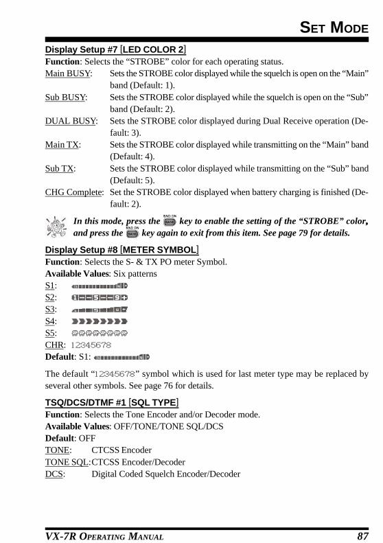
VX-7R OPERATING MANUAL 87
SET MODE
Display Setup #7 [LED COLOR 2]Function: Selects the “STROBE” color for each operating status.Main BUSY: Sets the STROBE color displayed while the squelch is open on the “Main”
band (Default: 1).Sub BUSY: Sets the STROBE color displayed while the squelch is open on the “Sub”
band (Default: 2).DUAL BUSY: Sets the STROBE color displayed during Dual Receive operation (De-
fault: 3).Main TX: Sets the STROBE color displayed while transmitting on the “Main” band
(Default: 4).Sub TX: Sets the STROBE color displayed while transmitting on the “Sub” band
(Default: 5).CHG Complete: Set the STROBE color displayed when battery charging is finished (De-
fault: 2).
In this mode, press the key to enable the setting of the “STROBE” color,,and press the key again to exit from this item. See page 79 for details.
Display Setup #8 [METER SYMBOL]Function: Selects the S- & TX PO meter Symbol.Available Values: Six patternsS1:S2:S3:S4:S5:CHR:Default: S1:
The default “ ” symbol which is used for last meter type may be replaced byseveral other symbols. See page 76 for details.
TSQ/DCS/DTMF #1 [SQL TYPE]Function: Selects the Tone Encoder and/or Decoder mode.Available Values: OFF/TONE/TONE SQL/DCSDefault: OFFTONE: CTCSS EncoderTONE SQL:CTCSS Encoder/DecoderDCS: Digital Coded Squelch Encoder/Decoder

VX-7R OPERATING MANUAL88
SET MODE
TSQ/DCS/DTMF #2 [TONE SET]Function: Setting of the CTCSS Tone Fre-quencyAvailable Values: 50 standard CTCSS tonesDefault: 100.0 Hz
In this mode, press the key toenable the setting of the tone, andpress the key again to exitfrom this item.
TSQ/DCS/DTMF #3 [DCS SET]Function: Setting of the DCS code.Available Values: 104 standard DCS codes.Default: 023
In this mode, press the key toenable the setting of the DCS code,and press the key again to exitfrom this item.
TSQ/DCS/DTMF #4 [DCS COMPLEMENT]Function: Enables/Disables “Inverted” DCS code decoding.Available Values: ENABLE/DISABLEDefault: DISABLE
TSQ/DCS/DTMF #5 [BELL]Function: Selects the CTCSS Bell ringer repetitions.Available Values: OFF/1/3/5/8/CONTINUEDefault: OFF
DCS CODE023 025 026 031 032 036 043 047 051 053
054 065 071 072 073 074 114 115 116 122
125 131 132 134 143 145 152 155 156 162
165 172 174 205 212 223 225 226 243 244
245 246 251 252 255 261 263 265 266 271
274 306 311 315 325 331 332 343 346 351
356 364 365 371 411 412 413 423 431 432
445 446 452 454 455 462 464 465 466 503
506 516 523 526 532 546 565 606 612 624
627 631 632 654 662 664 703 712 723 731
732 734 743 754 – – – – – –
CTCSS TONE FREQUENCY (Hz)
67.0 69.3 71.9 74.4 77.0 79.7
82.5 85.4 88.5 91.5 94.8 97.4
100.0 103.5 107.2 110.9 114.8 118.8
123.0 127.3 131.8 136.5 141.3 146.2
151.4 156.7 159.8 162.2 165.5 167.9
171.3 173.8 177.3 179.9 183.5 186.2
189.9 192.8 196.6 199.5 203.5 206.5
210.7 218.1 225.7 229.1 233.6 241.8
250.3 254.1 – – – –

VX-7R OPERATING MANUAL 89
SET MODE
TSQ/DCS/DTMF #6 [SPLIT TONE]Function: Enables/disables split CTCSS/DCS coding.Available Values: OFF/ONDefault: OFFWhen this Menu Item is set to ON, you can see the following additional parameters afterthe “DCS” parameter while selecting the Menu Item (TSQ/DCS/DTMF #1: SQL TYPE),:D CODE: DCS Encode only (“ ” icon will appear while operating)TONE DC: Encodes a CTCSS Tone and Decodes a DCS code
(the “ ” icon will appear during operation)DC TONE: Encodes a DCS code and Decodes a CTCSS Tone
(the “ ” icon will appear during operation)Select the desired operating mode from the selections shown above.
TSQ/DCS/DTMF #7 [DTMF DIALER]Function: Enables/disables the DTMF Autodial feature.Available Values: ON/OFFDefault: OFF
TSQ/DCS/DTMF #8 [DTMF SET]Function: Programming of the DTMF Autodialer. See page 38 for details.
Scan Modes #1 [CH COUNTER]Function: Selects the Channel Counter Search Width.Available Values: ±5 MHz/±10 MHz/± 50 MHz/±100 MHzDefault: ± 5 MHz
Scan Modes #2 [EDGE BEEP]Function: Enables/disables the Band-edge beeper while selecting the frequency by theDIAL.Available Values: ON/OFFDefault: OFFWhen this Menu Item is set to “ON,” a beep will sound when the frequency reaches theband edge while selecting the VFO frequency by the DIAL.

VX-7R OPERATING MANUAL90
SET MODE
Scan Modes #3 [RESUME]Function: Selects the Scan Resume mode.Available Values: 3SEC/5SEC/7SEC/10SEC/BUSY/HOLDDefault: 5 SEC3SEC/5SEC/7SEC/10SEC: The scanner will hold for the selected period (seconds), then
resume whether or not the other station is still transmitting.BUSY: The scanner will hold until the signal disappears, then will
resume when the carrier drops.HOLD: The scanner will stop when a signal is received, and will not
restart.
Scan Modes #4 [SCAN LAMP]Function: Enables/disables the Scan lamp while paused.Available Values: ON/OFFDefault: ON
Scan Modes #5 [SMART SEARCH]Function: Selects the Smart Search Sweep mode.Available Values: 1/CONTINUOUSDefault: 11: The transceiver sweeps the current band once in each direction starting
on the current frequency. All channels where activity is present (up to 15in each direction) are loaded into the Smart Search memories. Whetheror not all 31 memories are filled, the search stops after one sweep in eachdirection.
CONTINUOUS:The transceiver makes a sweep in each direction as with the “1(SINGLE)”mode, but if all 31 channels are not filled after the first sweep, the radiocontinues sweeping until they are all filled.
Scan Modes #6 [SPEC-ANALYZER 1]Function: Selects the Spectrum Analyzer Sweep mode.Available Values: 1/CONTINUOUSDefault: 11: The transceiver sweeps the current band once.CONTINUOUS:The transceiver sweeps the current band repeatedly until the Spectrum
Analyzer is turned off
Scan Modes #7 [SPEC-ANALYZER 2]Function: Enables/disables the audio output of the center frequency (q) when the Spec-trum Analyzer is activated in the Amateur band.Available Values: ON/OFFDefault: OFF

VX-7R OPERATING MANUAL 91
SET MODE
Measurement #1 [SENSOR DISPLAY]Function: Selects the display of the sensor units’ information.Available Values: TIME/DC/TEMP/WAVE/BARO/ALTI/WX/OFFDefault: TIME
The barometric pressure (BARO), altitude (ALTI), and Weather (WX) informa-tion require the optional SU-1.
Measurement #2 [WAVE MONITOR]Function: Select the Wave Form to be monitored.Available Values: ALL/RX SIGNAL/TX MODULATIONDefault: ALLALL: Indicates the RX Audio wave form and TX Audio modulation wave
form.RX SIGNAL: Indicates the RX Audio modulation wave form.TX MODULATION: Indicates the TX Audio modulation wave form.
Measurement #3 [TEMP UNIT]Function: Selects the measurement units for the Temperature sensor.Available Values: °C/°FDefault: Depends on the transceiver version
Measurement #4 [BARO UNIT]Function: Selects the measurement units for the Barometric Pressure sensor (requires op-tional SU-1).Available Values: hpa/mbar/mmHg/inchDefault: Depends on the transceiver version
Measurement #5 [BARO OFFSET]Function: Correcting the Barometric Pressure (requires optional SU-1). See page 70 fordetails.
Measurement #6 [ALTITUDE UNIT]Function: Select the measurement units for the Altimeter (requires optional SU-1).Available Values: m/ftDefault: Depends on the transceiver version
Measurement #7 [ALTITUDE OFFSET]Function: Correcting the Altimeter (requires optional SU-1). See page 71 for details.
Save Modes #1 [APO]Function: Setting of the Automatic Power-Off time.Available Values: OFF/30 min/1 hour/3 hours/5 hours/8 hoursDefault: OFF
VX-7R OPERATING MANUAL92
SET MODE
Save Modes #2 [RX SAVE]Function: Selects the Receive-mode Battery Saver interval (“sleep” ratio).Available Values: OFF/200mS(1:1)/300mS(1:1.5)/500mS(1:2.5)/1s(1:5)/2s(1:10)Default: 200mS(1:1)
Save Modes #3 [TX SAVE]Function: Enables/disables the Transmit Battery Saver.Available Values: ON/OFFDefault: OFF
Save Modes #4 [TOT]Function: Setting of the TOT time.Available Values: OFF/1 min/2.5 min/5 min/10 minDefault: OFFThe time-out timer shuts off the transmitter after continuous transmission of the programmedtime.
Save Modes #5 [ON TIMER]Function: Set the ON Timer time.Available Values: OFF/00:00 ~ 23:59Default: OFFThe ON Timer turns on the radio at the programmed time.
Save Modes #6 [OFF TIMER]Function: Set the OFF Timer time.Available Values: OFF/00:00 ~ 23:59Default: OFFThe OFF Timer turns off the radio at the programmed time.
ARTS #1 [ARTS BEEP]Function: Select the Beep option during ARTS operation.Available Values: IN RANGE/ALWAYS/OFFDefault: IN RANGERANGE: Beeps sound only when the radio first detects that you are within range.ALWAYS: Beeps sound every time a polling transmission is received from the other sta-
tion (every 15 or 25 seconds when in range).OFF: No alert beeps sound.
ARTS #2 [ARTS INTERVAL]Function: Select the Polling Interval during ARTS operation.Available Values: 15 SEC/25 SECDefault: 25 SECThis setting determines how often the other station will be polled during ARTS operation.

VX-7R OPERATING MANUAL 93
SET MODE
ARTS #3 [CW ID]Function: Program and activate the CW Identifier (used during ARTS operation). Seepage 37 for details.
Misc Setup #1 [BCLO]Function: Enables/disables the Busy Channel Lock-Out feature.Available Values: ON/OFFDefault: OFF
Misc Setup #2 [HOME/REV]Function: Selects the function of the key..Available Values: HOME/REVDefault: Depends on the transceiver version.HOME: Pressing this key instantly recalls a favorite “Home” channel.REV: Pressing this key reverses the transmit and receive frequencies during repeater
operation.
Misc Setup #3 [MON/T-CAL]Function: Selects the MONI key (just below the PTT switch) function.Available Values: MONI/T-CALDefault: Depends on the transceiver version.MONI: Pressing the MONI key causes the Noise/Tone Squelch to be over-ridden, allow-
ing you to listen for weak (or non-encoded) signals.T-CAL: Pressing the MONI key activates a 1750-Hz burst tone, used for repeater access in
many countries.

VX-7R OPERATING MANUAL94
Misc Setup #4 [MON-F CHANGE]Function: Exchange the functions between the key and the MONI keys on the leftside of the radio.Available Values: FUNC/MONIDefault: FUNCFUNC: The key is defined as the “Alternate” function key. Press the key to
activate the “Secondary” key mode. Meanwhile, the MONI key is defined as the“Monitor” function, which overrides the Noise and Tone Squelch quieting sys-tems.
MONI: The key is defined as the “Monitor” function, which overrides the Noise andTone Squelch quieting systems. Meanwhile, the MONI key is defined as the “Al-ternate” function key. The “Secondary” key mode is activated while pressing andholding in the MONI key.
Important Note: When you define the left side of the MONI key to be the “Alternate”function (“MONI” selected), the “Alternate” function is activated while pressing and hold-ing in the MONI key, NOT by pressing and holding in the MONI key for 2 second.
Example:(1) To enter the Set mode, press the key while pressing and holding in the MONI key..(2) To store a frequency into a memory channel.
1. Select the desired frequency.2. Press the key while pressing and holding in the MONI key.3. Rotate the DIAL to select the desired memory channel, as desired.4. Press the key to store the frequency into the selected memory..
Misc Setup #5 [EMG SET]Function: Select the alarms utilized when the Emergency function is engaged.Available Values: BEEP+STROBE/BEEP/STROBE1/STROBE2/STROBE3/STROBE4/STROBE5/BEAMDefault: BEEP+STROBEBEEP+STROBE: Loud “Alarm” sounds along with flashing of the
STROBE in sequential colors.BEEP: Loud “Alarm” sounds.STROBE1: Flashes the STROBE in sequential colors.STROBE2: Continuation changes the STROBE in sequential
colors.STROBE3, STROBE4, & STROBE5: Flashes the STROBE in white (3: Slow flashing,
4: Medium flashing, 5: Rapid flashing)BEAM: The STROBE glows continuously in white.
SET MODE

VX-7R OPERATING MANUAL 95
Misc Setup #6 [HALF DEVIATION]Function: Reducing the Deviation level by 50%.Available Values: ON/OFFDefault: OFF
Misc Setup #7 [VOX SENS]Function: Enables/disables VOX operation; sets VOX sensitivity.Available Values: OFF/HIGH/LOWDefault: OFF
Misc Setup #8 [VOX DELAY]Function: Selects the VOX delay (“hang”) time.Available Values: 0.5S/1S/2SDefault: 0.5S
Misc Setup #9 [BAND LINK]Function: Enables/disables the BAND Link feature.Available Values: ON/OFFDefault: OFFWhen this feature is set to “ON,” the “Main” and “Sus” bands are “slaved” so that theychange frequency together.
Misc Setup #10 [VFO MODE]Function: Selects or disables the VFO Band edge for the current band.Available Values: ALL/BANDDefault: BANDALL: When the VFO frequency reaches the high edge of the current band, the VFO
frequency will jump to the low band edge of the next band (or vice versa).BAND: When the VFO frequency reaches the high band edge of the current band, the
VFO frequency will jump to the low band edge of the current band (or vice versa).
Misc Setup #11 [FONT EDITOR]Function: Editing of the User font. See page 77 for details.
Misc Setup #12 [ICON SET]Function: Enables/disables the Icon display.Available Values: ON/OFFDefault: OFF
Misc Setup #13 [ICON EDITOR]Function: Editing of the User Icon. See page 74 for details.
Misc Setup #14 [ICON SELECT]Function: ICON selection. See page 73 for details.
SET MODE

VX-7R OPERATING MANUAL96
Misc Setup #15 [CLOCK SHIFT]Function: Shifting of CPU clock frequency.Available Values: ON/OFFDefault: OFFThis function is only used to move a spurious response “birdie,” should it fall on a desiredfrequency.
Misc Setup #16 [TIME SET]Function: Sets the Clock time. See page 69 for details.
Misc Setup #17 [LANGUAGE]Function: Selects the language for the Set (Menu) mode selections.Available Values: ENGLISH/JAPANESEDefault: ENGLISH
Misc Setup #18 [ATT]Function: Enables/disables the Front-end Attenuator.Available Values: ON/OFFDefault: OFF
Misc Setup #19 [MIC MONITOR]Function: Enables/disables the Microphone Monitor feature.Available Values: ON/OFFDefault: OFF
Misc Setup #20 [WX ALERT]Function: Enables/disables the Weather Alert FeatureAvailable Values: ON/OFFDefault: OFF
SET MODE

VX-7R OPERATING MANUAL 97
1. Make sure that the transceiver is off. Remove the hard or soft case, if used.2. Remove the battery pack.3. Locate the connector for the SU-1 under the caution seal in the battery compartment
on the back of the radio, just peel off the caution seal.4. Align the connector on the SU-1 with the transceiver’s connector and gently press the
unit into place.5. Affix the new (supplied) caution seal, and replace the battery.6. Installation is now complete.
INSTALLATION OF THE SU-1 (OPTION)
Important noteThe Barometric Pressure/Altitude features of the optional SU-1 are designed to besupplemental aids for the information of the user, and are not intended to be asubstitute for accurate, calibrated Barometer or Altimeter devices used for naviga-tion critical to personal safety.

VX-7R OPERATING MANUAL98
GeneralFrequency Ranges: MAIN Rx: 05-1.8 MHz (BC Band)
1.8-30 MHz (SW Band)30-59 MHz (50 MHz HAM: USA version)30-76 MHz (50 MHz HAM: EXP version)59-108 MHz (FM: USA version)76-108 MHz (FM: EXP version)108-137 MHz (Air Band)137-174 MHz (144 MHz HAM)174-222 MHz (VHF-TV)222-225 MHz (220 MHz HAM: USA version)225-420 MHz (ACT1: Action Band 1:USA version)222-420 MHz (ACT1: Action Band 1: EXP version)420-470 MHz (430 MHz HAM)470-729 MHz (UHF-TV: USA version)470-800 MHz (UHF-TV: EXP version)800-999 MHz (ACT2: Action Band 2, cellular Blocked)SUB Rx: 50-54 MHz
137-174 MHz420-470 MHz
Tx: 50-54 MHz (MAIN & SUB)144-146 MHz or 144-148 MHz (MAIN & SUB)222-225 MHz ((MAIN, USA version)430-440 MHz or 430-450 MHz (MAIN & SUB)
Channel Steps: 5/9/10/12.5/15/20/25/50/100 kHzEmission Type: F2, F3, A3
Frequency Stability: ±5 ppm (–10 °C to +50 °C [+14 °F to +122 °F])Repeater Shift: ±600 kHz (144 MHz), ±1.6 MHz (222 MHz), ±1.6/5.0/7.6 MHz (430 MHz)Emission Type: A3/F2/F3
Antenna Impedance: 50 OhmsSupply Voltage: Nominal: 7.4 V DC, Negative Ground
Operating:10-16 V DC, Negative Ground (EXT DC jack)Current Consumption: 200 mA (Mono Band Receive)
(Approx.) 240 mA (Dual Band Receive)67 mA (Mono Band Receive, Standby, Saver Off)100 mA (Dual Band Receive, Standby, Saver Off)28 mA (Mono Band Receive, Standby, Saver On “Save Ratio 1:5”)34 mA (Dual Band Receive, Standby, Saver On “Save Ratio 1:5”)200 µA (Auto Power Off)1.6 A (50 MHz, 5 W Tx)1.7A (144 MHz, 5W Tx)1.0 A (220 MHz, 0.3 W Tx)1.9 A (430 MHz, 5W Tx)
Operating Temperature: –20 °C to +60 °C (–4 °F to +140 °F)Case Size (W x H x D): 60 x 90 x 28.5 mm (2.4 x 3.5 x 1.1 inch) w/o knob & antenna
Weight (Approx.): 260 g (9.2 oz) with FNB-80LI & antenna
SPECIFICATIONS

VX-7R OPERATING MANUAL 99
TransmitterRF Power Output: 5.0 W (@7.4 V & 13.8 V EXT DC IN)
0.3W (@7.4 V & 13.8 V EXT DC IN, 222 MHz1.0W (@7.4 V & 13.8 V EXT DC IN, 50 MHz AM)
Modulation Type: F2, F3: Variable Reactance (MAIN & SUB)A3: Low Level Amplitude Modulation (MAIN, 50 MHz)
Maximum Deviation: ±5 kHz F2/F3Spurious Emission: At least 60 dB down (@ Tx HI/L3)
At least 50 dB down (@ Tx L2/L1)Microphone Impedance: 2K Ohms
ReceiverCircuit Type: N-FM, AM: Double-Conversion Superheterodyne
W-FM: Triple-Conversion SuperheterodyneIF: MAIN Rx
1st: 47.25 MHz (N-FM, AM), 45.8 MHz (W-FM)2nd: 450 kHz (N-FM, AM), 10.7 MHz (W-FM)3rd: 1 MHz (W-FM)
SUB Rx1st: 46.35 MHz2nd: 450 kHz
Sensitivity: MAIN Rx:3.0 µV for 10 dB S/N (0.5-30 MHz, AM)0.5 µV (TYP) for 12 dB SINAD (30-50, N-FM)0.16 µV for 12 dB SINAD (50-54, N-FM)1.0 µV (TYP) for 12 dB SINAD (57-76, N-FM)1.0 µV (TYP) for 12 dB SINAD (76-108, W-FM)1.5 µV (TYP) for 10 dB SN (108-137, AM)0.2 µV for 12 dB SINAD (137-140, N-FM)0.16 µV for 12 dB SINAD (140-150, N-FM)0.2 µV for 12 dB SINAD (150-174, N-FM)0.3 µV for 12 dB SINAD (174-225, N-FM)0.5 µV for 12 dB SINAD (300-350, N-FM)0.2 µV for 12 dB SINAD (350-400, N-FM)0.18 µV for 12 dB SINAD (400-470, N-FM)0.35 µV for 12 dB SINAD (470-540, W-FM)3.0 µV (TYP) for 12 dB SINAD (540-800, W-FM)1.0 µV (TYP) for 12 dB SINAD (800-999, N-FM) (Cellular Blocked)
SUB Rx:0.18 µV for 12 dB SINAD (50-54, N-FM)0.18 µV for 12 dB SINAD (137-174, N-FM)0.2 µV for 12 dB SINAD (420-470, N-FM)
Selectivity: 12 kHz/25 kHz (–6dB/–60dB: N-FM, AM)200 kHz/300 kHz (–6dB/–20dB: W-FM)
AF Output: 200 mW @ 8 Ohms for 10 % THD (@ 7.4 V DC)400 mW @ 8 Ohms for 10 % THD (@ 13.8 V DC)
Specifications are subject to change without notice, and are guaranteed within the 50/144/222/430 MHz amateur bands only.
SPECIFICATIONS
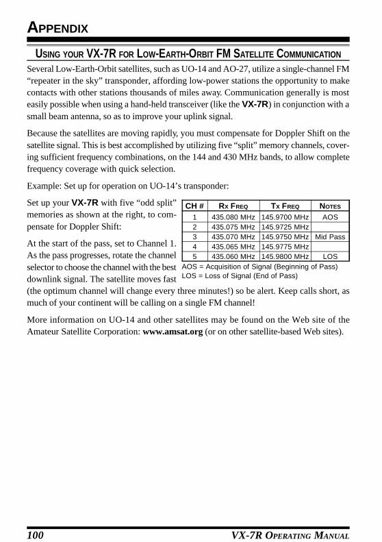
VX-7R OPERATING MANUAL100
APPENDIX
USING YOUR VX-7R FOR LOW-EARTH-ORBIT FM SATELLITE COMMUNICATION
Several Low-Earth-Orbit satellites, such as UO-14 and AO-27, utilize a single-channel FM“repeater in the sky” transponder, affording low-power stations the opportunity to makecontacts with other stations thousands of miles away. Communication generally is mosteasily possible when using a hand-held transceiver (like the VX-7R) in conjunction with asmall beam antenna, so as to improve your uplink signal.
Because the satellites are moving rapidly, you must compensate for Doppler Shift on thesatellite signal. This is best accomplished by utilizing five “split” memory channels, cover-ing sufficient frequency combinations, on the 144 and 430 MHz bands, to allow completefrequency coverage with quick selection.
Example: Set up for operation on UO-14’s transponder:
Set up your VX-7R with five “odd split”memories as shown at the right, to com-pensate for Doppler Shift:
At the start of the pass, set to Channel 1.As the pass progresses, rotate the channelselector to choose the channel with the bestdownlink signal. The satellite moves fast(the optimum channel will change every three minutes!) so be alert. Keep calls short, asmuch of your continent will be calling on a single FM channel!
More information on UO-14 and other satellites may be found on the Web site of theAmateur Satellite Corporation: www.amsat.org (or on other satellite-based Web sites).
AOS = Acquisition of Signal (Beginning of Pass)LOS = Loss of Signal (End of Pass)
CH #12345
RX FREQ
435.080 MHz435.075 MHz435.070 MHz435.065 MHz435.060 MHz
TX FREQ
145.9700 MHz145.9725 MHz145.9750 MHz145.9775 MHz145.9800 MHz
NOTES
AOS
Mid Pass
LOS

1. Changes or modifications to this device not expressly approved by VERTEXSTANDARD could void the user’s authorization to operate this device.
2. This device complies with part 15 of the FCC Rules. Operation is subject tothe following two conditions; (1) this device may not cause harmfulinterference, and (2) this device must accept any interference includinginterference that may cause undesired operation.
3. The scanning receiver in this equipment is incapable of tuning, or readilybeing altered, by the User to operate within the frequency bands allocatedto the Domestic public Cellular Telecommunications Service in Part 22.
This device complies with RSS-210 of Industry Canada. Operation is subjectto the following two conditions; (1) this device may not cause interference, and(2) this device must accept any interference, including interference that maycause undesirable operation of the device.
WARNING: MODIFICATION OF THIS DEVICE TO RECEIVE CELLULARRADIOTELEPHONE SERVICE SIGNALS IS PROHIBITED UNDER FCC RULESAND FEDERAL LAW.

Printed in JapanCopyright 2002VERTEX STANDARD CO., LTD.All rights reserved.
No portion of this manualmay be reproducedwithout the permission ofVERTEX STANDARD CO., LTD. 0204L-AY
E H 0 0 9 M 1 0 1