tripping instability of ring stiffened cylinders induced...
TRANSCRIPT
1
Abstract
The dynamic stability of a ring-stiffened cylindrical hull structure subjected to
underwater explosion is investigated using a finite element approach. The arbitrary
Lagrangian-Eulerian (ALE) method in LS-DYNA is employed for the analysis. One
of the detrimental collapse instabilities in tripping is identified in the ring stiffened
cylindrical structure. Tripping can be defined as lateral-torsional buckling behaviour
of the ring stiffener. The stiffener tripping-form of collapse is a sudden and drastic
reduction in load-carrying ability resulting in total failure.
Progressive tripping phenomenon is observed to identify the triggering instability
that causes total collapse. Sensitivity analysis is conducted to investigate the region
that is unstable with respect to stiffener tripping. The stability region is proposed in
terms of ring-stiffener sizing with respect to hull structure configuration.
Keywords: underwater explosion, arbitrary Lagrangian-Eulerian method, tripping.
1 Introduction
Underwater explosion (UNDEX) is a highly important and complex problem for
naval surface ships and submarines. Detonating high explosives in underwater
generates a shock wave and a pulsating gas bubble. The dynamic responses of
submerged structures impinged upon by UNDEX have received considerable
attention since the 1950s. When UNDEX occurs within the vicinity of the structure,
structure deformation occurs because of the tripping phenomenon. This
phenomenon, which pertains to lateral-torsional buckling, is serious problem that
contributes to the damage response of submerged structures.
In this study, sensitivity analysis is conducted to observe the progressive tripping
and identify the triggering instability that causes total collapse. On the basis of the
result, the region that is stable against tripping throughout the parametric study is
proposed. Two types of the submerged structure investigated are the rectangular ring
Paper 171 Tripping Instability of Ring Stiffened Cylinders induced by Underwater Explosions Y.O. Shin1 and Y.S. Shin2 1 Daewoo Shipbuilding & Marine Engineering Co., Ltd. Seoul, South Korea 2 Ocean Systems Engineering Division Korea Advanced Institute of Science and Technology, Daejeon, South Korea
©Civil-Comp Press, 2012 Proceedings of the Eleventh International Conference on Computational Structures Technology, B.H.V. Topping, (Editor), Civil-Comp Press, Stirlingshire, Scotland

2
stiffened cylindrical shell and tee ring stiffened cylindrical shell with hemispherical
end caps. This model was simulated to study the dynamic behavior of structure
instead of the physical testing since the physical testing of submerged structure
subjected to underwater explosion is enormous cost and limited by environmental
concern.
The response of structure is calculated by Arbitrary Lagrangian-Eulerian method
(ALE). ALE is used to the fluid-structure interaction and LS-DYNA is used to
analyze the structure subjected to UNDEX.
2 Theoretical background
2.1 Shock loading
The rate of energy release during the detonation process results in greater destructive
power. At very early times the gas pressure acts on the surrounding water, thereby
resulting in the compression and radial motion of the water. Thus, a shock wave is
generated and emitted. Shock wave velocity steadily increases within the explosive
until velocity exceeds the speed of sound in the explosive. About 53% of the energy
of the explosion energy is transmitted in the shock wave and about 47% of the
explosion energy generates a gas bubble.
The UNDEX pressure equation proposed by Cole [1] can be expressed as
follows;
(1)
This shock formula is empirically determined as the equation of pressure history.
It is accurate at a distance of 10 to 100 radius of the explosive, where Pmaxis the peak
pressure (pa) in the shock front, t is the time elapsed after the arrival of the shock
(ms), and θ denotes the exponential decay time constant (ms) which is a good
approximation of the pressure that is greater than one-third of the peak pressure
value [1].
(pa) (2)
(ms) (3)
The empirical equation of the maximum bubble radius (Amax) and gas bubble
period (T) can be expressed as follows;
(m) (4)
(5)
(s)

3
where K1, K2, K3, K4, K5, A1 and A2 are constants that depend on charge type (Table
1). R (in m) is the distance between the explosive charge and target and D denotes
the depth (in m) of the explosive. W represents the weight of the explosive charge in
lb. This empirical equation result is satisfied at a depth is between 50% and 80% of
the maximum radius [2].
Description Parameter Explosive type
HBX-1 TNT PETN
Pmax K1 22,347.6 22,505 24,589
A1 1.144 1.18 1.194
Decay constant K2 0.056 0.058 0.052
A2 -0.247 -0.185 -0.257
Bubble period K5 4.761 4.268 4.339
Bubble radius K6 14.14 12.67 12.88
Table 1: Shock wave parameter value.
2.2 Arbitrary Lagrangian-Eulerian Method
In choosing a solution method for simulating problems, an appropriate
kinematical description of the continuum is a fundamental consideration.
In the Lagrangian approach, the computational mesh follows the associated
material particle during motion. The Lagrangian description enables the easy tracing
of free surfaces and interfaces between different materials. Its weakness is its
inability to follow large distortions of the computational domain without resorting to
frequent remeshing operations [3, 4].
In the Eulerian approach, the computational mesh is fixed using the Navier-
Stokes equation and the continuum moves with respect to the grid. The Eulerian
description large distortions in the continuum motion can be handled with relative
ease, but generally at the expense of precise interface definition and resolution of
flow details [3, 4].
To compensate for the shortcoming of a purely Lagrangian and purely Eulerian
description, another approach that combines the best features of the two has been
developed. In this approach, called the ALE method, the nodes of the computational
mesh may move with the continuum in normal Lagrangian fashion, be fixed in an
Eulerian manner or move in some arbitrary specified manner to yield a continuous
rezoning capability. Because of the freedom offered by the ALE description in
moving the computational mesh, greater distortions of the continuum can be handled
than is possible using a purely Lagrangian method, and with more resolution than is
afforded by a purely Eulerian approach.
The numerical analysis conducted in this study features an ALE finite element
code. LS-DYNA is used for the numerical analysis in this investigation. ALE
hydrocodes use both Lagrangian and Eulerian hydrocodes that perform automatic
rezoning. An ALE hydrocode involves a Lagrangian time step followed by a remap
or advection phase [3, 4].
4
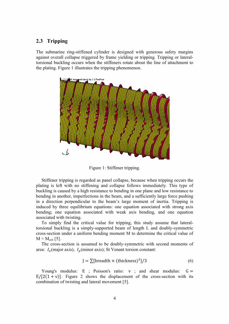
2.3 Tripping
The submarine ring-stiffened cylinder is designed with generous safety margins
against overall collapse triggered by frame yielding or tripping. Tripping or lateral-
torsional buckling occurs when the stiffeners rotate about the line of attachment to
the plating. Figure 1 illustrates the tripping phenomenon.
Figure 1: Stiffener tripping.
Stiffener tripping is regarded as panel collapse, because when tripping occurs the
plating is left with no stiffening and collapse follows immediately. This type of
buckling is caused by a high resistance to bending in one plane and low resistance to
bending in another, imperfections in the beam, and a sufficiently large force pushing
in a direction perpendicular to the beam’s large moment of inertia. Tripping is
induced by three equilibrium equations: one equation associated with strong axis
bending; one equation associated with weak axis bending, and one equation
associated with twisting.
To simply find the critical value for tripping, this study assume that lateral-
torsional buckling is a simply-supported beam of length L and doubly-symmetric
cross-section under a uniform bending moment M to determine the critical value of
M = Mcrit [5].
The cross-section is assumed to be doubly-symmetric with second moments of
area: (major axis), (minor axis); St Venant torsion constant:
(6)
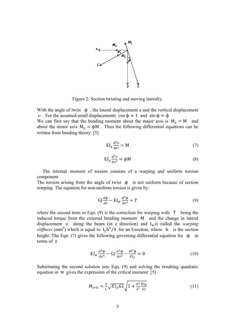
Young's modulus: ; Poisson's ratio: ; and shear modulus: . Figure 2 shows the displacement of the cross-section with its
combination of twisting and lateral movement [5].
5
Figure 2: Section twisting and moving laterally.
With the angle of twist , the lateral displacement u and the vertical displacement
. For the assumed small displacements and
We can first say that the bending moment about the major axis is and
about the minor axis . Then the following differential equations can be
written from bending theory: [5]
(7)
(8)
The internal moment of torsion consists of a warping and uniform torsion
component.
The torsion arising from the angle of twist is not uniform because of section
warping. The equation for non-uniform torsion is given by:
(9)
where the second term in Eqn. (9) is the correction for warping with being the
induced torque from the external bending moment and the change in lateral
displacement along the beam (in z direction) and is called the warping
stiffness (mm6) which is equal to
for an I-section, where is the section
height. The Eqn. (7) gives the following governing differential equation for in
terms of
(10)
Substituting the second solution into Eqn. (9) and solving the resulting quadratic
equation in gives the expression of the critical moment: [5]
(11)
6
As the name suggests, lateral torsional buckling is a phenomenon including both
out of plane buckling and twisting of the cross-section. This leads to a beam
displacement that includes contribution from lateral displacement and the angle of
twist.
The twisting of the cross-section includes components of warping torsion and St
Vennant’s torsion. And the resistance of the cross-section to this twisting is
dependent on , the warping constant, and , the St Vennant’s torsion and the
polar moment of inertia.
The critical moment of the cross-section will vary based on the end restraint, the
moment gradient, and the placement of the load.
2.4 Effective plastic strain (EPS)
To calculate the plastic strains, three properties are used to characterize the material
behavior;
A yield function, which gives the yield condition that specifies the state of
multiaxial stress corresponding to start of plastic flow
A flow rule, which relates the plastic strain increments to the current stresses and
the stress increments
A hardening rule, which specifies how the yield function is modified during
plastic flow
The yield function has the general form at time t,
(12)
Where denotes state variables that depend on the material characterization.
The instantaneous material response is elastic if
(13)
and elastic or plastic depending on the loading condition if
(14)
whereas tfy > 0 is inadmissible. Hence the relation Eqn.(14) represents the yield
condition, which must hold throughout the plastic response.[6]
Assuming that for the material the associated flow rule is applicable during
plastic response the function tfy in the flow rule is used to obtain the plastic strain
increments
(15)
where is scalar to be determined.
Effective plastic strain is follows;

7
(16)
Effective plastic strain is a monotonically increasing scalar value which is
calculated incrementally as a function of , the plastic component of the rate of
deformation tensor Eqn.(16). It is grows whenever the material is actively yielding,
i.e., whenever the state of stress is on the yield surface.[6]
3 Numerical model description
3.1 Simulation
The fluid and structure model are created using TrueGrid software and then are
exported to LS-DYNA code to analyze the transient dynamic behavior. Fig. 20
depicts a stiffened cylindrical structure with a depth of 150 m, subjected to shock
wave induced by 65 kg TNT detonated 1 m away from the side of the structure. The
total simulation time is 0.5 s but the explosive charge explodes at 0.2 s because the
hydrostatic pressure is stabilized for 0.2 s. The time step is 1.0x10⁻⁵
s, which is
acceptable for the mesh size of this model.
Figure 3: Scenarios of simulation
3.2 Water and air model
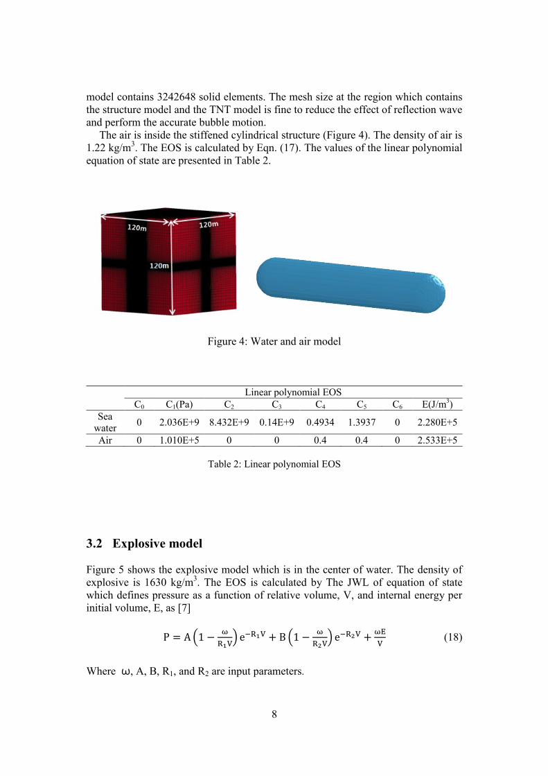
Figurre.4 show the water model with a depth, width and height of 120 m. The water
density is 1025 kg/m3. The equation of state (EOS) is calculated by the linear
polynomial equation of state which is expressed as, [7]
(17)
The initial pressure of EOS is determined by multiplying the C4 and E. For the
condition of 150 m water depth, the initial pressure of EOS was changed. The water
8
model contains 3242648 solid elements. The mesh size at the region which contains
the structure model and the TNT model is fine to reduce the effect of reflection wave
and perform the accurate bubble motion.
The air is inside the stiffened cylindrical structure (Figure 4). The density of air is
1.22 kg/m3. The EOS is calculated by Eqn. (17). The values of the linear polynomial
equation of state are presented in Table 2.
Figure 4: Water and air model
Linear polynomial EOS
C0 C1(Pa) C2 C3 C4 C5 C6 E(J/m3)
Sea
water 0 2.036E+9 8.432E+9 0.14E+9 0.4934 1.3937 0 2.280E+5
Air 0 1.010E+5 0 0 0.4 0.4 0 2.533E+5
Table 2: Linear polynomial EOS
3.2 Explosive model
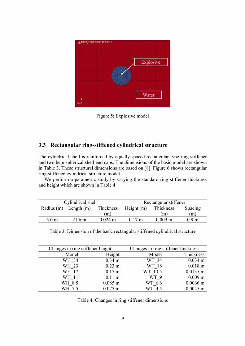
Figure 5 shows the explosive model which is in the center of water. The density of
explosive is 1630 kg/m3. The EOS is calculated by The JWL of equation of state
which defines pressure as a function of relative volume, V, and internal energy per
initial volume, E, as [7]
(18)
Where ω, A, B, R1, and R2 are input parameters.
9
Figure 5: Explosive model
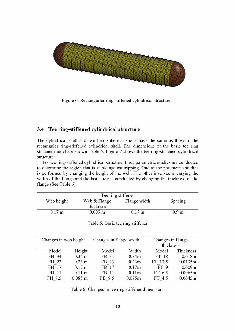
3.3 Rectangular ring-stiffened cylindrical structure
The cylindrical shell is reinforced by equally spaced rectangular-type ring stiffener
and two hemispherical shell end caps. The dimensions of the basic model are shown
in Table 3. These structural dimensions are based on [8]. Figure 6 shows rectangular
ring-stiffened cylindrical structure model
We perform a parametric study by varying the standard ring stiffener thickness
and height which are shown in Table 4.
Cylindrical shell Rectangular stiffener
Radius (m) Length (m) Thickness
(m)
Height (m) Thickness
(m)
Spacing
(m)
5.0 m 21.6 m 0.024 m 0.17 m 0.009 m 0.9 m
Table 3: Dimension of the basic rectangular stiffened cylindrical structure
Changes in ring stiffener height Changes in ring stiffener thickness
Model Height Model Thickness
WH_34 0.34 m WT_34 0.034 m
WH_23 0.23 m WT_18 0.018 m
WH_17 0.17 m WT_13.5 0.0135 m
WH_11 0.11 m WT_9 0.009 m
WH_8.5 0.085 m WT_6.6 0.0066 m
WH_7.5 0.075 m WT_4.5 0.0045 m
Table 4: Changes in ring stiffener dimensions
10
Figure 6: Rectangurlar ring stiffened cylindrical structures.
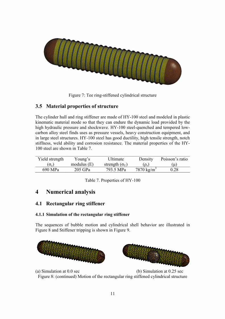
3.4 Tee ring-stiffened cylindrical structure
The cylindrical shell and two hemispherical shells have the same as those of the
rectangular ring-stiffened cylindrical shell. The dimensions of the basic tee ring
stiffener model are shown Table 5. Figure 7 shows the tee ring-stiffened cylindrical
structure.
For tee ring-stiffened cylindrical structure, three parametric studies are conducted
to determine the region that is stable against tripping. One of the parametric studies
is performed by changing the height of the web. The other involves is varying the
width of the flange and the last study is conducted by changing the thickness of the
flange (See Table 6).
Tee ring stiffener
Web height Web & Flange
thickness
Flange width Spacing
0.17 m 0.009 m 0.17 m 0.9 m
Table 5: Basic tee ring stiffener
Changes in web height Changes in flange width Changes in flange
thickness
Model Height Model Width Model Thickness
FH_34 0.34 m FB_34 0.34m FT_18 0.018m
FH_23 0.23 m FB_23 0.23m FT_13.5 0.0135m
FH_17 0.17 m FB_17 0.17m FT_9 0.009m
FH_11 0.11 m FB_11 0.11m FT_6.5 0.0065m
FH_8.5 0.085 m FB_8.5 0.085m FT_4.5 0.0045m
Table 6: Changes in tee ring stiffener dimensions
11
Figure 7: Tee ring-stiffened cylindrical structure
3.5 Material properties of structure
The cylinder hull and ring stiffener are made of HY-100 steel and modeled in plastic
kinematic material mode so that they can endure the dynamic load provided by the
high hydraulic pressure and shockwave. HY-100 steel-quenched and tempered low-
carbon alloy steel finds uses as pressure vessels, heavy construction equipment, and
in large steel structures. HY-100 steel has good ductility, high tensile strength, notch
stiffness, weld ability and corrosion resistance. The material properties of the HY-
100 steel are shown in Table 7.
Yield strength
(σy)
Young’s
modulus (E)
Ultimate
strength (σU)
Density
(ρs)
Poisson’s ratio
(μ)
690 MPa 205 GPa 793.5 MPa 7870 kg/m3 0.28
Table 7. Properties of HY-100
4 Numerical analysis
4.1 Rectangular ring stiffener
4.1.1 Simulation of the rectangular ring stiffener
The sequences of bubble motion and cylindrical shell behavior are illustrated in
Figure 8 and Stiffener tripping is shown in Figure 9.
(a) Simulation at 0.0 sec (b) Simulation at 0.25 sec
Figure 8: (continued) Motion of the rectangular ring stiffened cylindrical structure
12
(c) Simulation at 0.36 sec (d) Simulation at 0.5 sec
Figure 8: (continued) Motion of the rectangular ring stiffened cylindrical structure
Figure 9: Tripping for rectangular ring stiffener
4.1.2 EPS measure points for the rectangular ring stiffener
To compare the deformation of the stiffener and cylinder, the EPS is measured at the
particular elements of the model that are influenced by the shockwave pressure and
bubble effect.
The particular elements of the model are shown in Figure 10. The element p1, p2
and p3 are used to measure the EPS of the plate while the others are to measure the
EPS of the stiffener. The element p3 is at the middle of the structure.
Figure 10: Measured elements of the model
13
4.1.3 Changing the height of the rectangular ring stiffener
The parametric studies on the change in web height, with web thickness kept
constant, are performed to investigate tripping behavior and structure deformation.
The simulation cases are listed in Table 4. Figure 11 shows the variations in the
EPS values of the stiffener with increasing hw/tw and constant stiffener web
thickness. And Figure 12 shows the variation in the EPS values of the cylindrical
shell.
As shown in Figure 11, determining the trend of tripping behavior for the
stiffener is a difficult task.
Figure 11 implies that as the height of the stiffener web increases, the EPS values
typically increase. Therefore, as the height of the stiffener increases, the deflection
of the rectangular ring-stiffened cylindrical structure also increases.
(a) s1 (b) s2 (c) s3
Figure 11: Variation of in the EPS values of the stiffener with increasing hw/tw and
the stiffener web thickness kept constant.
(a) p1 (b) p2 (c) p3
Figure 12: Variation of in the EPS values of the plate with increasing hw/tw k and
stiffener web thickness kept constant.
4.1.4 Changing the thickness of the rectangular ring stiffener
The parametric studies on the change in web thickness, with web height kept
constant, are performed to investigate tripping behavior and structure deformation.
The simulation cases are listed in Table 4.
14
Figure 13 illustrates the variations in EPS values for the stiffener with increase
hw/tw and constant stiffener web height. And Figure 14 shows the variation in the
EPS values of the cylindrical shell.
Figure 13 and Figure 14 indicate that increasing the thickness of the stiffener web
effectively diminishes the possibility of tripping and deformation of cylindrical shell.
(a) s1 (b) s2 (c) s3
Figure 13: Variation in the EPS values of the stiffener with increasing hw/tw and the
stiffener web height kept constant.
(a) p1 (b) p2 (c) p3
Figure 14: Variations in the EPS for the plate with increasing hw/tw and constant
stiffener web height.
4.2 Tee ring stiffener
4.2.1 Simulation of the tee ring stiffener
The stiffener tripping is shown in Figure 15.
15
Figure15: Tripping for tee ring stiffener
4.2.2 Changing the web height of the tee ring stiffener
The EPS is measured at particular elements of the flange and cylinder which are
affected by the shockwave pressure and bubble effect.
Elements f1, f2 and f3 are measured to compare the deformations of the stiffener.
Elements p1, p2 and p3 are measured to compare the deformations of the cylinder.
The measured elements for the cylinder are the same as those measured for the
rectangular ring-stiffened cylindrical shell. The elements for the flange and cylinder
are shown in Figure 16.
Figure 16: Measured elements of the model for the tee ring-stiffened cylindrical
structure
4.2.3 Changing the web height of the tee ring stiffener
The parametric studies are performed by varying the height of the stiffener web,
with the web thickness, flange width and flange thickness kept constant to
investigate stiffener tripping behavior and cylinder deformation. The simulation
cases are listed in Table 5.
16
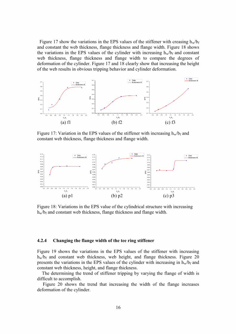
Figure 17 show the variations in the EPS values of the stiffener with creasing hw/bf
and constant the web thickness, flange thickness and flange width. Figure 18 shows
the variations in the EPS values of the cylinder with increasing hw/bf and constant
web thickness, flange thickness and flange width to compare the degrees of
deformation of the cylinder. Figure 17 and 18 clearly show that increasing the height
of the web results in obvious tripping behavior and cylinder deformation.
(a) f1 (b) f2 (c) f3
Figure 17: Variation in the EPS values of the stiffener with increasing hw/bf and
constant web thickness, flange thickness and flange width.
(a) p1 (b) p2 (c) p3
Figure 18: Variations in the EPS value of the cylindrical structure with increasing
hw/bf and constant web thickness, flange thickness and flange width.
4.2.4 Changing the flange width of the tee ring stiffener
Figure 19 shows the variations in the EPS values of the stiffener with increasing
hw/bf and constant web thickness, web height, and flange thickness. Figure 20
presents the variations in the EPS values of the cylinder with increasing in hw/bf and
constant web thickness, height, and flange thickness.
The determining the trend of stiffener tripping by varying the flange of width is
difficult to accomplish.
Figure 20 shows the trend that increasing the width of the flange increases
deformation of the cylinder.

17
(a) f1 (b) f2 (c) f3
Figure 19: Variations in the EPS values of the stiffener with increasing hw/bf and
constant web thickness, web height and flange thickness
(a) p1 (b) p2 (c) p3
Figure 20: Variation in the EPS values of the cylindrical structure with increasing
hw/bf and constant the web thickness, web height and flange thickness.
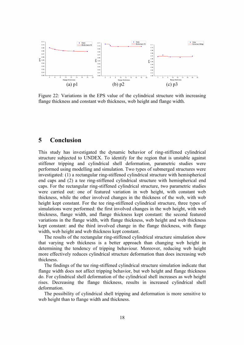
4.2.5 Changing the flange thickness of the tee ring stiffener
Figure 21 shows the variations in the EPS values of the stiffener with increasing
flange thickness and constant web thickness, web height, and flange width. Figure
22 presents the variations in the EPS values of the cylinder with increasing in flange
thickness and constant web thickness, height, and flange width.
As the thickness of the flange increases, stiffener tripping and cylinder
deformation decrease
(a) f1 (b) f2 (c) f3
Figure 21: Variations in the EPS of the stiffener with increasing flange thickness and
constant the web thickness, web height, and flange width.
18
(a) p1 (b) p2 (c) p3
Figure 22: Variations in the EPS value of the cylindrical structure with increasing
flange thickness and constant web thickness, web height and flange width.
5 Conclusion
This study has investigated the dynamic behavior of ring-stiffened cylindrical
structure subjected to UNDEX. To identify for the region that is unstable against
stiffener tripping and cylindrical shell deformation, parametric studies were
performed using modelling and simulation. Two types of submerged structures were
investigated: (1) a rectangular ring-stiffened cylindrical structure with hemispherical
end caps and (2) a tee ring-stiffened cylindrical structure with hemispherical end
caps. For the rectangular ring-stiffened cylindrical structure, two parametric studies
were carried out: one of featured variation in web height, with constant web
thickness, while the other involved changes in the thickness of the web, with web
height kept constant. For the tee ring-stiffened cylindrical structure, three types of
simulations were performed: the first involved changes in the web height, with web
thickness, flange width, and flange thickness kept constant: the second featured
variations in the flange width, with flange thickness, web height and web thickness
kept constant: and the third involved change in the flange thickness, with flange
width, web height and web thickness kept constant.
The results of the rectangular ring-stiffened cylindrical structure simulation show
that varying web thickness is a better approach than changing web height in
determining the tendency of tripping behaviour. Moreover, reducing web height
more effectively reduces cylindrical structure deformation than does increasing web
thickness.
The findings of the tee ring-stiffened cylindrical structure simulation indicate that
flange width does not affect tripping behavior, but web height and flange thickness
do. For cylindrical shell deformation of the cylindrical shell increases as web height
rises. Decreasing the flange thickness, results in increased cylindrical shell
deformation.
The possibility of cylindrical shell tripping and deformation is more sensitive to
web height than to flange width and thickness.
19
Acknowledgement
This research was supported by WCU (World Class University) program through
the National Research Foundation of Korea funded by the Ministry of Education,
Science and Technology (R31-2008-000-10045-0)
Reference
[1] Cole, R.H., “Underwater Explosions”, Princeton University Press, 1948
[2] Shin, Y.S., “Ship shock modeling and simulation for far-field underwater
explosion”, Computers & Structure, 82, 2211-2219, 2004
[3] Mohamed, S., and David, J.B., “Arvitrary Lagrangian-Eulerian and Fluid-
Structure Interaction”, John Wiley & Sons, Inc., New Jersey, 2010.
[4] Donea, J., Huerta, A., Ph. Ponthot, J., and Rodriguez-Ferran, Q., “Arbitrary
Lagrangian-Eulerian methods”, Encyclopedia of Computational Mechanics,
2004.
[5] Theodeore V.G., Andrea E.S., “Structural stability of steel: concepts and
applications for structural engineers”, John Wiley & Sons, Inc, New jersey,
2008
[6] Klaus-Jurgen Bathe, “Finite Element Procedures”, New jersey, United States
of America, 1996.
[7] LSTC, “LS/DYNA3D User’s Manual, Version 971”, Livermore Soft
Technology Corp., 2007
[8] Radha, P., and Rajagopabn, K., “Random Polar Sampling Technique for
Reliability Analysis of submarine pressure hull”, Journal of Naval
Architecture and marine Engineering, 2004.