tritium inventories and containment philosophy for the fuel … · – calculation of systems...
TRANSCRIPT

Forschungszentrum Karlsruhein der Helmholtz-Gemeinschaft
IAEA TM on Fusion Power Plant Safety, July 10-13, 2006 Ioana R. Cristescu slide # 1
FUSION FZK - EURATOM ASSOCIATION
Tritium Inventories and Containment Philosophy for the Fuel cycle of ITER
I. R. Cristescu 1), I. Cristescu 1), L. Doerr 1), M. Glugla 1), D. Murdoch 2)
1) Forschungszentrum Karlsruhe, Tritium Laboratory, Germany2) EFDA CSU Garching, Germany
Forschungszentrum Karlsruhein der Helmholtz-Gemeinschaft
IAEA TM on Fusion Power Plant Safety, July 10-13, 2006 Ioana R. Cristescu slide # 2
FUSION FZK - EURATOM ASSOCIATION
Outline of the presentation
• Tritium Inventories in The Fuel cycle of ITER– TRIMO – dynamic software for tritium inventory simulation in ITER– Minimization of tritium inventories in FC of ITER
• Tritium confinement principles
• Detritiation systems– Atmosphere Detritiation system– Water Detritiation system
• Closing remarks
Forschungszentrum Karlsruhein der Helmholtz-Gemeinschaft
IAEA TM on Fusion Power Plant Safety, July 10-13, 2006 Ioana R. Cristescu slide # 3
FUSION FZK - EURATOM ASSOCIATION
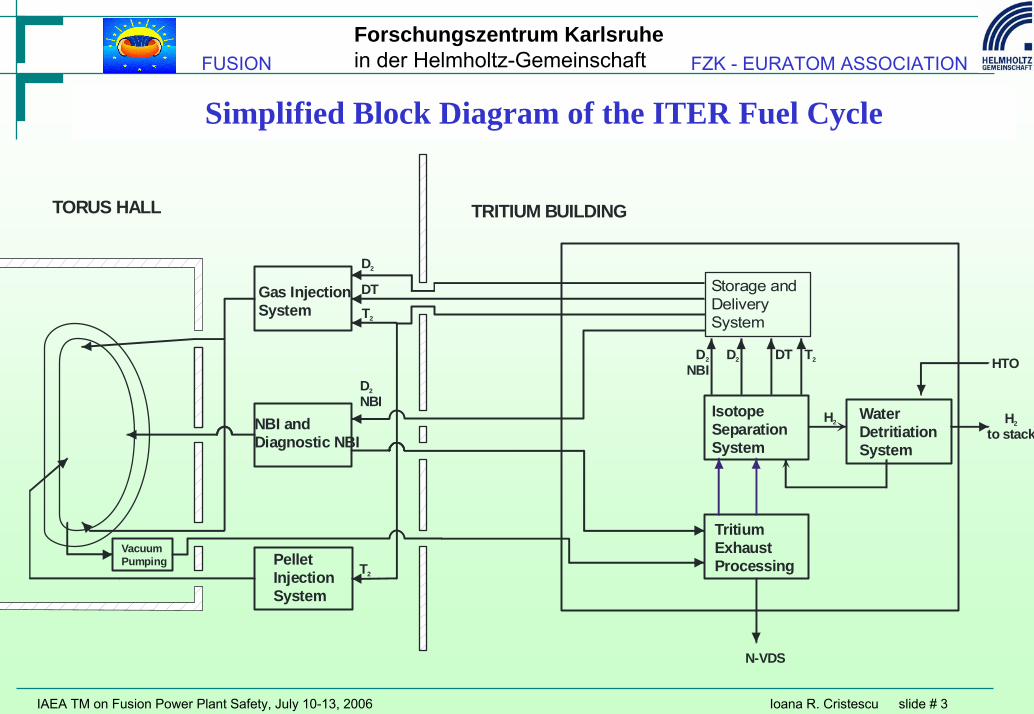
Simplified Block Diagram of the ITER Fuel Cycle
Gas InjectionSystem
PelletInjectionSystem
NBI andDiagnostic NBI
TORUS HALL TRITIUM BUILDING
Storage andDeliverySystem
D2DNBI
2 DT T2
TritiumExhaustProcessing
H2
D2
DT
T2
T2
VacuumPumping
HTO
Hto stack
2
N-VDS
DNBI
2
IsotopeSeparationSystem
Water DetritiationSystem
Forschungszentrum Karlsruhein der Helmholtz-Gemeinschaft
IAEA TM on Fusion Power Plant Safety, July 10-13, 2006 Ioana R. Cristescu slide # 4
FUSION FZK - EURATOM ASSOCIATION
Dynamic Mathematical Modeling of the ITER Fuel Cycle
• Motivation to develop a dynamic code for FC functioning:– ITER is a pulse machine, operating under burn and dwell
• 450s (3000s) during burn fuel is introduced, 1350s (9000s) during dwell no fuelling is taking place
• Necessity to support the detailed system design by validated codes– Calculation of systems performance under different operational conditions
• An ITER fuel cycle simulation model has to address the following topics:– To evaluate the behavior of the sub-systems in dynamic regimes (operating scenarios), whether
the sub-systems, equipment sizes were appropriate (or properly designed). – To assess the cycle time from injection back to the storage and delivery system – To assess tritium inventories in each subsystem in different operating conditions, taking into
account the tritium inventory history of the sub-systems

Forschungszentrum Karlsruhein der Helmholtz-Gemeinschaft
IAEA TM on Fusion Power Plant Safety, July 10-13, 2006 Ioana R. Cristescu slide # 5
FUSION FZK - EURATOM ASSOCIATION
Dynamic Mathematical Modeling of the ITER Fuel Cycle
• Several steps to develop a dynamic code for FC of fusion machines have been made– Residence-time approach gives high uncertainties– CFTSIM model (2000, under ITER supervision) built on elements from FLOSHEET (CD steady
state) and DYNSIM (dynamic simulator)
• Source code of CFTSIM transferred to TLK in 2004
• TRIMO – Build on elements from CFTSIM (mainly ISS)– Extensive work have been carried out to implement on-going changes in FC design– Developed with EFDA support– Source code owned by TLK– Draft documentation issued

Forschungszentrum Karlsruhein der Helmholtz-Gemeinschaft
IAEA TM on Fusion Power Plant Safety, July 10-13, 2006 Ioana R. Cristescu slide # 6
FUSION FZK - EURATOM ASSOCIATION
Software life-cycle diagram - TRIMO
RequirementsSpecification
FunctionalSpecification
ArchitecturalDesign
DetailedDesign
Coding and Implementation
IntegrationTesting and
Commissioning
Operation,Maintenance and
Enhancement
To quantify time variation of T inventories in the Fuel Cycle for several operational scenarios
User-friendly graphical interfaces for input parametersGraphical outputs: T inventories, streams composition and flowrates
Modular structure: for each FC subsystem a module is assigned
Library for hydrogenic isotopes mixtures properties at low temperatures (non-idealities)
Documented (logical diagrams)
Modular tests:CD column moduleWDS module

Forschungszentrum Karlsruhein der Helmholtz-Gemeinschaft
IAEA TM on Fusion Power Plant Safety, July 10-13, 2006 Ioana R. Cristescu slide # 7
FUSION FZK - EURATOM ASSOCIATION
FC design - TRIMO FCSubsystem
Physical and chemical processes Inflows Outflows Model Design characteristics
Fuelling → Freezing of DT gas→Pressurized gas flows SDS Torus Lump Fuelling pattern
Neutral BeamInjection Vacuum flows SDS Torus,
TEPLump, parametric,vacuum flows
Regeneration pattern, roughing pumpcharacteristics
Torus→Plasma →Plasma-wallinteractions →Chargeexchange →Retention
Fuelling,NBI
Vacuumpumping
Lump, power-lawpressure, parametric
Power, Volume, Burn-up rate, Waltemperature
Vacuumpumping Vacuum flows Torus TEP Lump, regeneration,
Vacuum flows
Regeneration pattern, cryopumpcharacteristics, duct geometry, roughingpump characteristics
TokamakExhaustProcessing
→Permeation → Flows →Chemical reactions Vacuum
pumping,NBI ISS Lump, parametric Pumps characteristics, buffer vessels
WaterDetritiationSystem
→Catalytic isotopicexchange →Electrolysis
Storagetanks, ISS
ISS,Stack
Dynamic 1-dimensionalmass transfer inmixtures
Column height, diameter, temperature,pressure, eletrolyser inventory, separationperformances
IsotopeSeparationSystem
→Cryogenic distillation TEP,WDS SDS,WDS
DynamicMulticomponendistillation
Columns height, diameter, temperature,pressure, inventory, separationperformances, intercolumn flows, flowcontrol valves, equilibrators
Storage andDeliverySystem
Adsorbtion, release fromstorage beds ISS
Fuelling,NBI Lump, parametric
Fuel handling strategy, Buffer vesselsimension, storage beds capacity, releaserate

Forschungszentrum Karlsruhein der Helmholtz-Gemeinschaft
IAEA TM on Fusion Power Plant Safety, July 10-13, 2006 Ioana R. Cristescu slide # 8
FUSION FZK - EURATOM ASSOCIATION
ISS Inventory

Forschungszentrum Karlsruhein der Helmholtz-Gemeinschaft
IAEA TM on Fusion Power Plant Safety, July 10-13, 2006 Ioana R. Cristescu slide # 9
FUSION FZK - EURATOM ASSOCIATION
Dynamics of Fuel cycle Inventories

Forschungszentrum Karlsruhein der Helmholtz-Gemeinschaft
IAEA TM on Fusion Power Plant Safety, July 10-13, 2006 Ioana R. Cristescu slide # 10
FUSION FZK - EURATOM ASSOCIATION
Tritium needed for operation• 120 Pam3/s 50%DT – basic fuelling scenario for ITER
Tritium necessary for non-interrupted burn/pulse
Tritium recovered during burn /pulse
Tritium recovered during dwell /pulse
Longpulse 480g 135g 345g*
Shortpulse 72g 12g 60g *
* tritium trapped in Torus and as tritiated impurities should be subtracted
• What influences the speed of tritium recovery in FC:– Tritium trapped in Torus– Vacuum pumping system regeneration pattern– Tritium trapped as impurities CQ4, Q2O– Ability of TEP, ISS to process the fuel fast
• Values of packing hold-up, CD column boiler inventory• Control system of ISS• ISS design

Forschungszentrum Karlsruhein der Helmholtz-Gemeinschaft
IAEA TM on Fusion Power Plant Safety, July 10-13, 2006 Ioana R. Cristescu slide # 11
FUSION FZK - EURATOM ASSOCIATION
T consumption and inventories within FC
• Besides the tritium from the FC, additionally 1 kg of tritium in Long Term Storage
• 0.39g T/450s burnpulse with a total burntime/ 10 years = 0.15 years
• Estimated total tritium consumption for ITER lifetime = 16 Kg
• Typical analysis where TRIMO is used:– Trade-off studies (ISS-TEP, WDS-ISS)– Various operational scenarios
• 8 typical fuelling cases at various T/D ratio and total flow rates for both short and longpulse
• Tritium inventory procedure in ITER
TotalgfedcbSDSgfedcbISSgfedcbVacuum PumpinggfedcbTEPgfedcbTorusgfedcbFuellinggfedcbIn_OutgfedcTritium Plantgfedc
Time(s)30,00020,00010,0000
g
500
450
400
350
300
250
200
150
100
50
0
– Evaluations of tritium inventory on various FC configuration (e.g. processing of ablated gas from pellet injector in ISS)
– Fuel handling in SDS for buffer vessels minimization
• The ultimate goal of these analysis is ensuring the FC functionality with tritium inventories minimization

Forschungszentrum Karlsruhein der Helmholtz-Gemeinschaft
IAEA TM on Fusion Power Plant Safety, July 10-13, 2006 Ioana R. Cristescu slide # 12
FUSION FZK - EURATOM ASSOCIATION
Validation on sub-systems: WDS and ISS
WDS for ITER WDS at TLKCECE process CECE processSolid polymer
electrolyserSolid polymer
electrolyserCatalyst/packing properties will be tested
for WDS designTritiated water feed flow rate:
20 Kg/h
Tritiated water feed flow rate:
1.5 Kg/hTritium activity in
water feed: 10 -100 Ci/Kg
Tritium activity in water feed:
1-10 Ci/Kg
ISS for ITER ISS at TLK
4 CryogenicDistillation columns
2 Cryogenic Distillation columns
Packing properties (HETP and hold-up) will be tested for ITER ISS design
Feed flow rate CD1: 280 mol/h
Feed flow rate: 45 mol/h
The influence of the return stream of CD1 ISS to WDS for further tritium depletion will be investigated, also in dynamic regimes (variable flow rates and composition) – integrated tests for TRIMO validation
Forschungszentrum Karlsruhein der Helmholtz-Gemeinschaft
IAEA TM on Fusion Power Plant Safety, July 10-13, 2006 Ioana R. Cristescu slide # 13
FUSION FZK - EURATOM ASSOCIATION
Effluents and releases
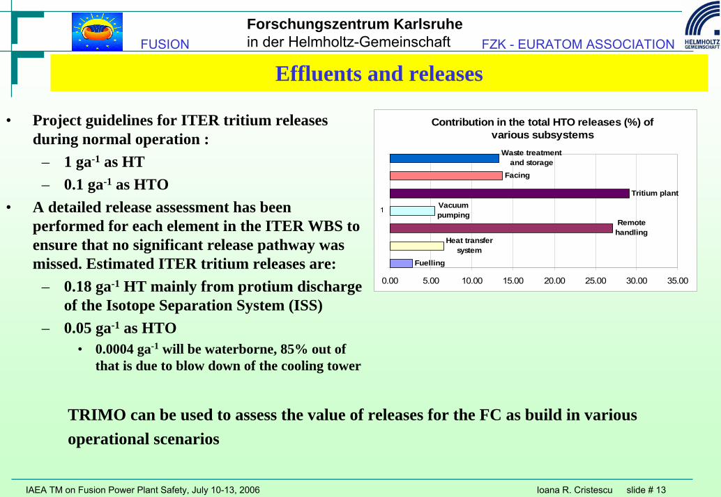
• Project guidelines for ITER tritium releases during normal operation :
– 1 ga-1 as HT– 0.1 ga-1 as HTO
• A detailed release assessment has been performed for each element in the ITER WBS to ensure that no significant release pathway was missed. Estimated ITER tritium releases are:
– 0.18 ga-1 HT mainly from protium discharge of the Isotope Separation System (ISS)
– 0.05 ga-1 as HTO• 0.0004 ga-1 will be waterborne, 85% out of
that is due to blow down of the cooling tower
Contribution in the total HTO releases (%) of various subsystems
Fuelling
Heat transfer system
Remote handling
Vacuum pumping
Tritium plant
Facing
Waste treatment and storage
0.00 5.00 10.00 15.00 20.00 25.00 30.00 35.00
1
TRIMO can be used to assess the value of releases for the FC as build in variousoperational scenarios

Forschungszentrum Karlsruhein der Helmholtz-Gemeinschaft
IAEA TM on Fusion Power Plant Safety, July 10-13, 2006 Ioana R. Cristescu slide # 14
FUSION FZK - EURATOM ASSOCIATION
Multiple Barrier Tritium Confinement Concept at TLK
Tritium InfrastructureTritium Transfer SystemIsotope Separation System... Primary System
Secondary System
Glove Box
ExperimentsCaperPetra...
Primary System
Secondary System
Glove Box
TritiumRetentionSystem
Primary SystemLeak Rate < 10-8 mbar l s-1
Tritium compatible materials...
Secondary SystemLeak Rate < 0.1vol % h-1
...
1. Stage(ClosedLoop)
Central Tritium Removal
2. Stage(Once
ThroughThanOut)
PrimaryOff-Gas
Treatment
ProvidesCentral
Under Pressure
LaboratoryVentilationRing Manifold
n-nnnnPIRCA±
TritiumRetentionSystem
k-kkkkPIRCA±
SafetyValve
SafetyValve
Under PressureControl
Under PressureControl
Stack
BuildingWall
TLKHoods
• Detritiation of all primary exhaust gases prior to discharge into the environment
•Detritiation systems for secondary and tertiary containments

Forschungszentrum Karlsruhein der Helmholtz-Gemeinschaft
IAEA TM on Fusion Power Plant Safety, July 10-13, 2006 Ioana R. Cristescu slide # 15
FUSION FZK - EURATOM ASSOCIATION
Primary and secondary containments
• Specifications for primary containments– Use of tritium compatible materials
• Qualification of materials for work in tritium environment when this is unavoidable (Nafionmembrane for the SPM electrolyser, catalysts - R&D to investigate the lifetime in the EFDA program and at TPL Japan)
– Definition of leak tightness– Outer jacket for tritium bearing components heated to temperatures above 150°C
• Evacuation of the jacket interspace for thermal insulation• Removal of tritium permeated through hot structural materials from the jacket
– protected against over-pressure, over-temperature • Specifications for secondary containments (glove-boxes, hardshell boxes)
– provided with detritiation systems and a purge and pressure control system – nitrogen atmosphere with very little oxygen (needed to convert leaked isotopic hydrogen
and hydrocarbons into water and carbon dioxide) – equipped with sensors to measure tritium level, temperature, pressure

Forschungszentrum Karlsruhein der Helmholtz-Gemeinschaft
IAEA TM on Fusion Power Plant Safety, July 10-13, 2006 Ioana R. Cristescu slide # 16
FUSION FZK - EURATOM ASSOCIATION
Example of over-pressure protection: ISS
PIR
RD
AV
RD
Rupture disk
Relief valve
Regulation valve
Normal flow
CD
Cold box
Processloop
Tritium monitor
Pump box
AV
Expansion vessel
ADS
RD
Hydrogen vessel
RV
PIR
PIR AV
RV
• Avoiding contamination of the refrigerant with tritium (intermediate hydrogen cooling pool)
• Recovery of process gas after expansion following warm shutdown.
• In case of tritium contamination, the coldbox and the hydrogen vessel discharge the overpressure into the atmosphere detritiation system.

Forschungszentrum Karlsruhein der Helmholtz-Gemeinschaft
IAEA TM on Fusion Power Plant Safety, July 10-13, 2006 Ioana R. Cristescu slide # 17
FUSION FZK - EURATOM ASSOCIATION
Integrated Atmosphere Detritiation system Configuration
• During normal operation a Normal Vent Detritiation system (700 Nm3/h) processes tritiated streams
• In the case of an off-normal event: – the HVAC systems branch ducts in each
room/area are switch to the re-circulation type room atmosphere detritiation systems (S-ADS 4500m3/h).
– the N-VDS is backed up by the once-through standby vent detritiation system SVDS 3000m3/h).
– the S-ADS and S-VDS ensure that:• Staggered negative pressure is maintained• the extracted air is detritiated to the
required low level before release into the environment
• tritium concentration in the affected room(s) is rapidly decreased.
Containment Volume(46,000 m )3
Secondary Enclosures
Secondary Enclosures
TritiumBuilding
TokamakBuilding
DivertorDrying SystemPit Free Volume
Rotary Dryer
Secondary Enclosures

Forschungszentrum Karlsruhein der Helmholtz-Gemeinschaft
IAEA TM on Fusion Power Plant Safety, July 10-13, 2006 Ioana R. Cristescu slide # 18
FUSION FZK - EURATOM ASSOCIATION
Standby Atmosphere Detritiation System

Forschungszentrum Karlsruhein der Helmholtz-Gemeinschaft
IAEA TM on Fusion Power Plant Safety, July 10-13, 2006 Ioana R. Cristescu slide # 19
FUSION FZK - EURATOM ASSOCIATION
Water Detritiation System
• Tritiated water will be produced in all ITER atmosphere detritiation systems (ADS)
• Typical tritium concentration 10Ci/kg with possibility of processing 500Ci/kg
• Combined Electrolysis Catalytic Exchange Process
– Very high detritiation factors are required to release WDS exhaust to stack
• R&D program to prove the capacity of WDS to further process the ISS hydrogen stream
• WDS is the only system in ITER that releases effluents into the environments without an additional detritiation system

Forschungszentrum Karlsruhein der Helmholtz-Gemeinschaft
IAEA TM on Fusion Power Plant Safety, July 10-13, 2006 Ioana R. Cristescu slide # 20
FUSION FZK - EURATOM ASSOCIATION
Closing remarks
• Fuel cycle of ITER:– quick recovery of tritium for recycling – low tritium inventory – safe handling and confinement of tritium– low effluents and releases
• Mature technologies for all subsystems• Sound modeling under validation • Existing infrastructure for accompanying R&D and further
developments