triton design toolbox -...
TRANSCRIPT
0800 CIRTEX (247 839) I [email protected] I WWW.CIRTEX.CO.NZ
STORMWATERMANAGEMENT
CIRTEX ADVANCED DESIGN SOLUTIONS
DESIGN
Designing with Triton® Stormwater System.
0800 CIRTEX (247 839) I [email protected] I WWW.CIRTEX.CO.NZ
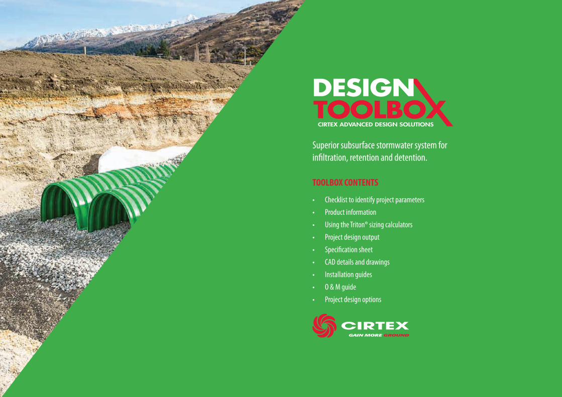
TOOLBOX CONTENTS
• Checklist to identify project parameters
• Product information
• Using the Triton® sizing calculators
• Project design output
• Specification sheet
• CAD details and drawings
• Installation guides
• O & M guide
• Project design options
Superior subsurface stormwater system for infiltration, retention and detention.
CIRTEX ADVANCED DESIGN SOLUTIONS
DESIGN


0800 CIRTEX (247 839) I [email protected] I WWW.CIRTEX.CO.NZ
CIRTEX ADVANCED DESIGN SOLUTIONS
DESIGN
Project Details Contact Details Date
Project Name Company
Project No. Engineer/Contractor
Location Ph.
Client Email
Request(Please explain your requirements)
Design Level
Level 1 (Technical Support) Level 2 (Project Concepts) Level 3 (3rd Party Design Cost TBD)
DATA INPUT SHEET FOR TRITON ® SWS
Project details and site constraints
Do you wish to retain water or is the object to allow soakage?
What is the total volume of water to be stored/soaked away?
What is the soakage rate?
How strong is the underlying soil?
Site configuration (attach plan or draw sketch)
Site constraints
Manhole locations
Utilities
If you require Cirtex to calculate volumes please advise...
Catchment area (define units)
Site runoff coefficients
Rainfall intensities (if not defined Cirtex will use HIRDS)
Design storm ARI
Sketch
Choose your preferred design level
0800 CIRTEX (247 839) I [email protected] I WWW.CIRTEX.CO.NZ
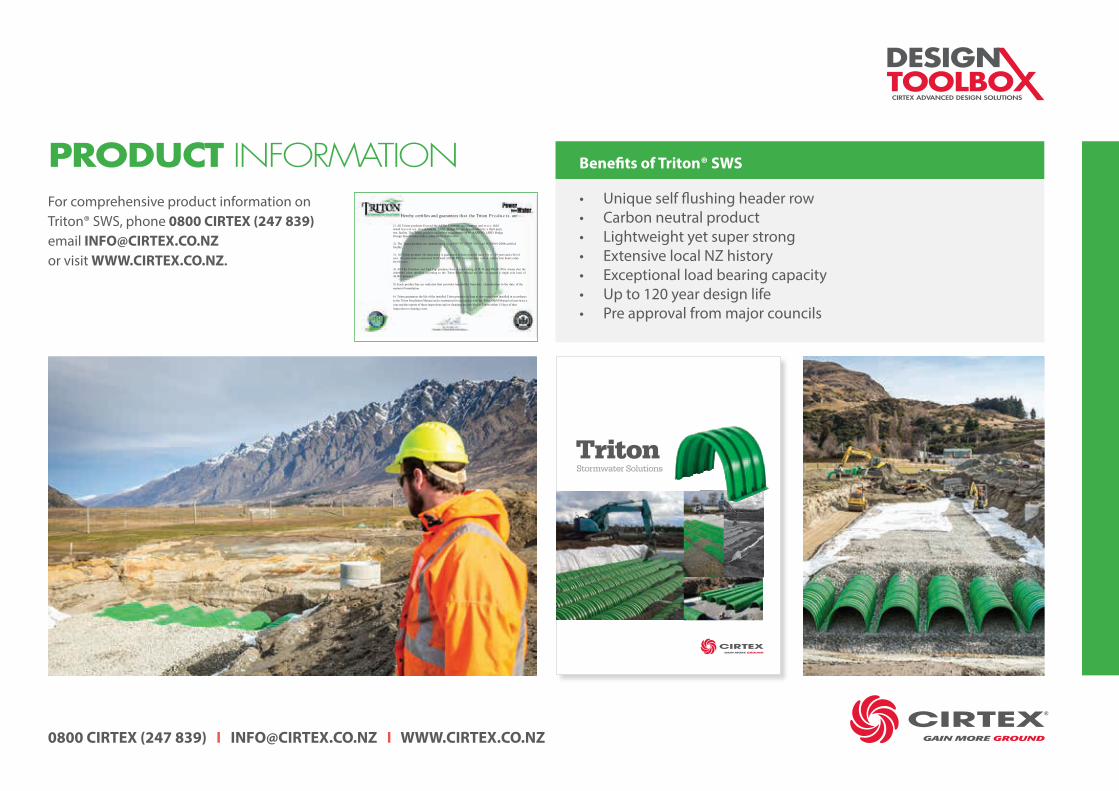
For comprehensive product information on Triton® SWS, phone 0800 CIRTEX (247 839) email [email protected] or visit WWW.CIRTEX.CO.NZ.
Benefits of Triton® SWS
• Unique self flushing header row• Carbon neutral product• Lightweight yet super strong• Extensive local NZ history• Exceptional load bearing capacity • Up to 120 year design life• Pre approval from major councils
PRODUCT INFORMATION
TritonStormwater Solutions
0800 CIRTEX (247 839) I [email protected] I WWW.CIRTEX.CO.NZ
CIRTEX ADVANCED DESIGN SOLUTIONS
DESIGN
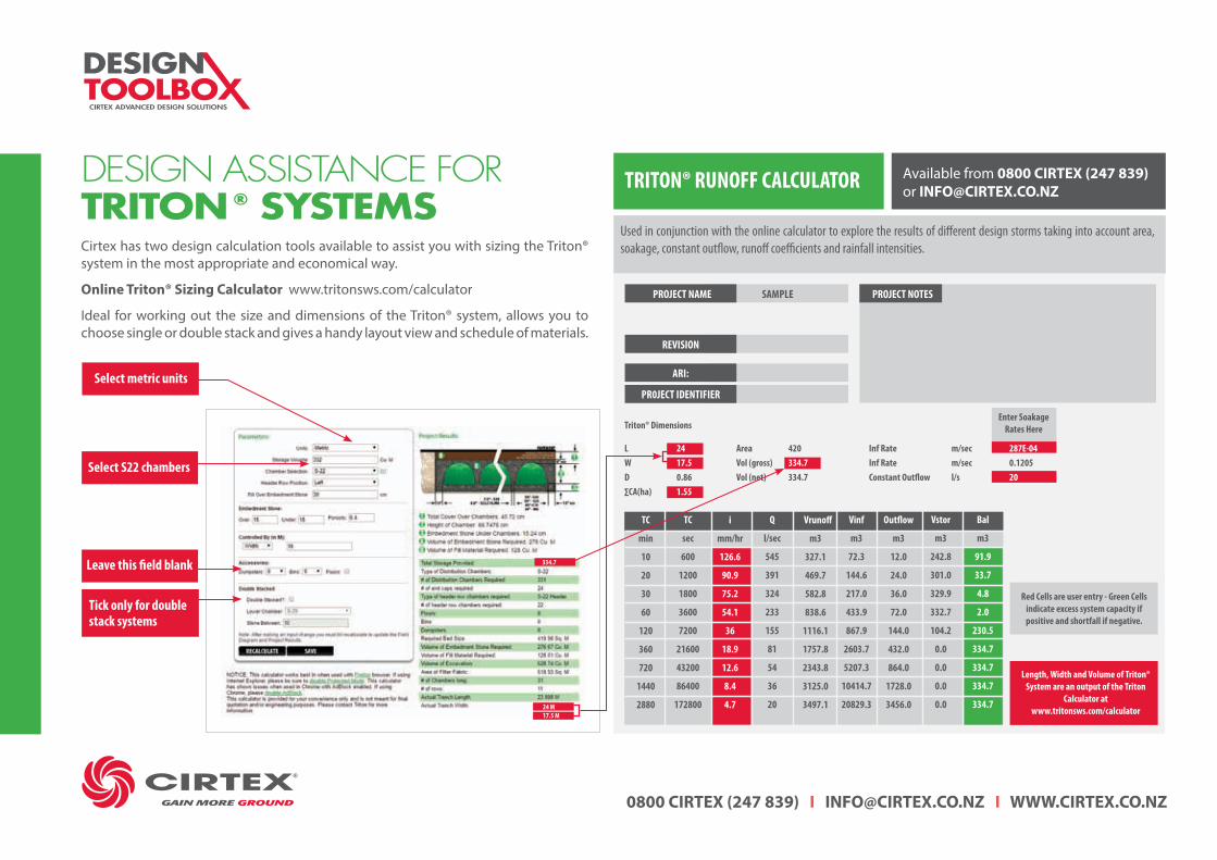
Cirtex has two design calculation tools available to assist you with sizing the Triton® system in the most appropriate and economical way.
Online Triton® Sizing Calculator www.tritonsws.com/calculator
Ideal for working out the size and dimensions of the Triton® system, allows you to choose single or double stack and gives a handy layout view and schedule of materials.
DESIGN ASSISTANCE FORTRITON ® SYSTEMS
TRITON® RUNOFF CALCULATOR Available from 0800 CIRTEX (247 839) or [email protected]
Used in conjunction with the online calculator to explore the results of different design storms taking into account area, soakage, constant outflow, runoff coefficients and rainfall intensities.
PROJECT NOTESPROJECT NAME
REVISION
ARI:
PR0JECT IDENTIFIER
SAMPLE
Red Cells are user entry - Green Cells indicate excess system capacity if positive and shortfall if negative.
Length, Width and Volume of Triton® System are an output of the Triton
Calculator at www.tritonsws.com/calculator
TC
min
10
20
30
60
120
360
720
1440
2880
VVrunoff
m3
327.1
469.7
582.8
838.6
1116.1
1757.8
2343.8
3125.0
3497.1
i
mm/hr
126.6
90.9
75.2
54.1
36
18.9
12.6
8.4
4.7
Outflow
m3
12.0
24.0
36.0
72.0
144.0
432.0
864.0
1728.0
3456.0
TC
sec
600
1200
1800
3600
7200
21600
43200
86400
172800
Vinf
m3
72.3
144.6
217.0
433.9
867.9
2603.7
5207.3
10414.7
20829.3
Q
l/sec
545
391
324
233
155
81
54
36
20
Vstor
m3
242.8
301.0
329.9
332.7
104.2
0.0
0.0
0.0
0.0
Bal
m3
91.9
33.7
4.8
2.0
230.5
334.7
334.7
334.7
334.7
Select S22 chambers
Select metric units
Leave this field blank
Tick only for double stack systems
24 M17.5 M
334.7
Triton® Dimensions
L 24W 17.5D 0.86∑CA(ha) 1.55
Area 420Vol (gross) 334.7Vol (net) 334.7
Inf Rate m/sec 287E-04Inf Rate m/sec 0.1205Constant Outflow l/s 20
Enter Soakage Rates Here
0800 CIRTEX (247 839) I [email protected] I WWW.CIRTEX.CO.NZ
NOTES :
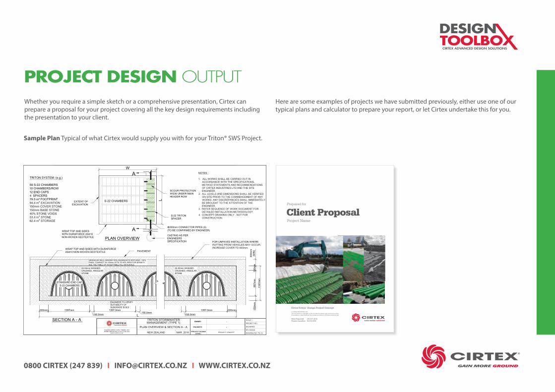
1. ALL WORKS SHALL BE CARRIED OUT INACCORDANCE WITH THE SPECIFICATIONS,METHOD STATEMENTS AND RECOMMENDATIONSOF CIRTEX INDUSTRIES LTD AND THE SITEENGINEER.
2. ALL LEVELS AND DIMENSIONS SHALL BE VERIFIEDON SITE PRIOR TO THE COMMENCEMENT OF ANYWORKS. ANY DISCREPANCIES SHALL IMMEDIATELYBE BROUGHT TO THE ATTENTION OF THEENGINEER.
3. REFER SEQUENCE OF WORK DOCUMENT FORDETAILED INSTALLATION METHODOLOGY.
4. CONCEPT DRAWING ONLY - NOT FORCONSTRUCTION.
³
³³
A
A
16 QUEEN STREET, KOPU, THAMES, 3578PHONE: 0800 247 839 ● FAX: 07 868 3435
WWW.CIRTEX.CO.NZ
PLAN OVERVIEW & SECTION A - A
NEW ZEALAND MAR. 2016
SCALE: /
REVISIONS:
OWNER:
ENGINEER: -
PROJECT DESIGNLEVEL: PROJECT CONCEPT
DESIGNED:
PROJECT NO: /
DRAWING NO: TS-1/4
-
Sample Plan Typical of what Cirtex would supply you with for your Triton® SWS Project.
Whether you require a simple sketch or a comprehensive presentation, Cirtex can prepare a proposal for your project covering all the key design requirements including the presentation to your client.
Here are some examples of projects we have submitted previously, either use one of our typical plans and calculator to prepare your report, or let Cirtex undertake this for you.
PROJECT DESIGN OUTPUT
© CIRTEX INDUSTRIES LTDThis document is copyright to the intended recipient only, and must not be forwarded or copied without the written permission of Cirtex Industries Ltd.
Cirtex Triton® Design Project Concept
Client ProposalProject Name
Prepared for
Date Prepared 28 JULY 2016 Project Location AUCKLAND
0800 CIRTEX (247 839) I [email protected] I WWW.CIRTEX.CO.NZ
CIRTEX ADVANCED DESIGN SOLUTIONS
DESIGN
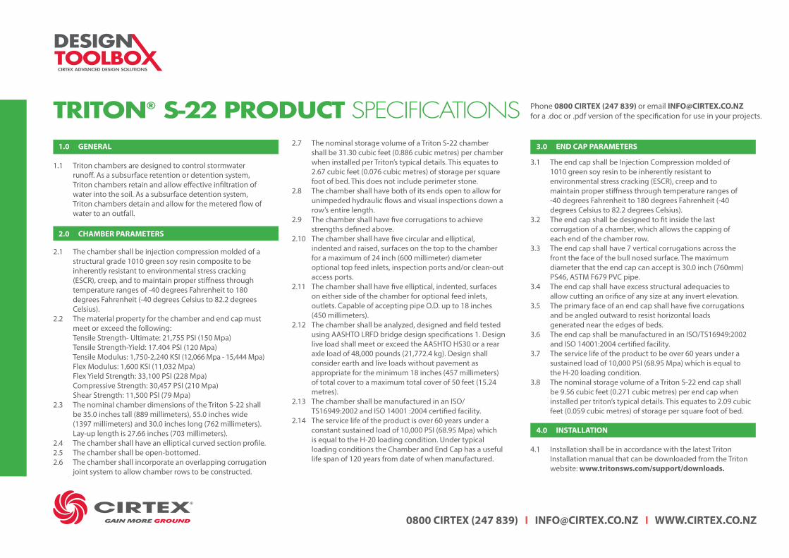
TRITON® S-22 PRODUCT SPECIFICATIONS Phone 0800 CIRTEX (247 839) or email [email protected] for a .doc or .pdf version of the specification for use in your projects.
1.1 Triton chambers are designed to control stormwater runoff. As a subsurface retention or detention system, Triton chambers retain and allow effective infiltration of water into the soil. As a subsurface detention system, Triton chambers detain and allow for the metered flow of water to an outfall.
2.1 The chamber shall be injection compression molded of a structural grade 1010 green soy resin composite to be inherently resistant to environmental stress cracking (ESCR), creep, and to maintain proper stiffness through temperature ranges of -40 degrees Fahrenheit to 180 degrees Fahrenheit (-40 degrees Celsius to 82.2 degrees Celsius). 2.2 The material property for the chamber and end cap must meet or exceed the following: Tensile Strength- Ultimate: 21,755 PSI (150 Mpa) Tensile Strength-Yield: 17.404 PSI (120 Mpa) Tensile Modulus: 1,750-2,240 KSI (12,066 Mpa - 15,444 Mpa) Flex Modulus: 1,600 KSI (11,032 Mpa) Flex Yield Strength: 33,100 PSI (228 Mpa) Compressive Strength: 30,457 PSI (210 Mpa) Shear Strength: 11,500 PSI (79 Mpa)2.3 The nominal chamber dimensions of the Triton S-22 shall be 35.0 inches tall (889 millimeters), 55.0 inches wide (1397 millimeters) and 30.0 inches long (762 millimeters). Lay-up length is 27.66 inches (703 millimeters).2.4 The chamber shall have an elliptical curved section profile.2.5 The chamber shall be open-bottomed.2.6 The chamber shall incorporate an overlapping corrugation joint system to allow chamber rows to be constructed.
2.7 The nominal storage volume of a Triton S-22 chamber shall be 31.30 cubic feet (0.886 cubic metres) per chamber when installed per Triton’s typical details. This equates to 2.67 cubic feet (0.076 cubic metres) of storage per square foot of bed. This does not include perimeter stone.2.8 The chamber shall have both of its ends open to allow for unimpeded hydraulic flows and visual inspections down a row’s entire length.2.9 The chamber shall have five corrugations to achieve strengths defined above.2.10 The chamber shall have five circular and elliptical, indented and raised, surfaces on the top to the chamber for a maximum of 24 inch (600 millimeter) diameter optional top feed inlets, inspection ports and/or clean-out access ports.2.11 The chamber shall have five elliptical, indented, surfaces on either side of the chamber for optional feed inlets, outlets. Capable of accepting pipe O.D. up to 18 inches (450 millimeters).2.12 The chamber shall be analyzed, designed and field tested using AASHTO LRFD bridge design specifications 1. Design live load shall meet or exceed the AASHTO HS30 or a rear axle load of 48,000 pounds (21,772.4 kg). Design shall consider earth and live loads without pavement as appropriate for the minimum 18 inches (457 millimeters) of total cover to a maximum total cover of 50 feet (15.24 metres).2.13 The chamber shall be manufactured in an ISO/ TS16949:2002 and ISO 14001 :2004 certified facility.2.14 The service life of the product is over 60 years under a constant sustained load of 10,000 PSI (68.95 Mpa) which is equal to the H-20 loading condition. Under typical loading conditions the Chamber and End Cap has a useful life span of 120 years from date of when manufactured.
3.1 The end cap shall be Injection Compression molded of 1010 green soy resin to be inherently resistant to environmental stress cracking (ESCR), creep and to maintain proper stiffness through temperature ranges of -40 degrees Fahrenheit to 180 degrees Fahrenheit (-40 degrees Celsius to 82.2 degrees Celsius). 3.2 The end cap shall be designed to fit inside the last corrugation of a chamber, which allows the capping of each end of the chamber row. 3.3 The end cap shall have 7 vertical corrugations across the front the face of the bull nosed surface. The maximum diameter that the end cap can accept is 30.0 inch (760mm) PS46, ASTM F679 PVC pipe. 3.4 The end cap shall have excess structural adequacies to allow cutting an orifice of any size at any invert elevation. 3.5 The primary face of an end cap shall have five corrugations and be angled outward to resist horizontal loads generated near the edges of beds. 3.6 The end cap shall be manufactured in an ISO/TS16949:2002 and ISO 14001:2004 certified facility. 3.7 The service life of the product to be over 60 years under a sustained load of 10,000 PSI (68.95 Mpa) which is equal to the H-20 loading condition. 3.8 The nominal storage volume of a Triton S-22 end cap shall be 9.56 cubic feet (0.271 cubic metres) per end cap when installed per triton’s typical details. This equates to 2.09 cubic feet (0.059 cubic metres) of storage per square foot of bed.
4.1 Installation shall be in accordance with the latest Triton Installation manual that can be downloaded from the Triton website: www.tritonsws.com/support/downloads.
1.0 GENERAL 3.0 END CAP PARAMETERS
4.0 INSTALLATION
2.0 CHAMBER PARAMETERS

0800 CIRTEX (247 839) I [email protected] I WWW.CIRTEX.CO.NZ
Triton® - Typical Cross Sections
Cirtex has a large number of CAD drawings for the Triton® Stormwater System, covering most applications. These can also be modified for your project as required.
Phone 0800 CIRTEX (247 839) or email [email protected] for a copy in either .pdf or .dwg formats.
CAD DETAILSNOTES :
1. ALL WORKS SHALL BE CARRIED OUT INACCORDANCE WITH THE SPECIFICATIONS,METHOD STATEMENTS AND RECOMMENDATIONSOF CIRTEX INDUSTRIES LTD AND THE SITEENGINEER.
2. ALL LEVELS AND DIMENSIONS SHALL BE VERIFIEDON SITE PRIOR TO THE COMMENCEMENT OF ANYWORKS. ANY DISCREPANCIES SHALL IMMEDIATELYBE BROUGHT TO THE ATTENTION OF THEENGINEER.
3. REFER SEQUENCE OF WORK DOCUMENT FORDETAILED INSTALLATION METHODOLOGY.
4. CONCEPT DRAWING ONLY - NOT FORCONSTRUCTION.
³
³³
A
A
16 QUEEN STREET, KOPU, THAMES, 3578PHONE: 0800 247 839 ● FAX: 07 868 3435
WWW.CIRTEX.CO.NZ
PLAN OVERVIEW & SECTION A - A
NEW ZEALAND MAR. 2016
SCALE: /
REVISIONS:
OWNER:
ENGINEER: -
PROJECT DESIGNLEVEL: PROJECT CONCEPT
DESIGNED:
PROJECT NO: /
DRAWING NO: TS-1/4
-
NOTES :
1. ALL WORKS SHALL BE CARRIED OUT INACCORDANCE WITH THE SPECIFICATIONS, METHODSTATEMENTS AND RECOMMENDATIONS OF CIRTEXINDUSTRIES LTD AND THE SITE ENGINEER.
2. ALL LEVELS AND DIMENSIONS SHALL BE VERIFIEDON SITE PRIOR TO THE COMMENCEMENT OF ANYWORKS. ANY DISCREPANCIES SHALL IMMEDIATELYBE BROUGHT TO THE ATTENTION OF THEENGINEER.
3. REFER SEQUENCE OF WORK DOCUMENT FORDETAILED INSTALLATION METHODOLOGY.
4. CONCEPT DRAWING ONLY - NOT FORCONSTRUCTION.
B
DESIGN DETAILS (1)
B
INLET PIPE (MAX D=600MM)
FOR UNPAVED INSTALLATIONWHERE RUTTING FROMVEHICLES MAY OCCUR,INCREASE COVER TO 600mm
16 QUEEN STREET, KOPU, THAMES, 3578PHONE: 0800 247 839 ● FAX: 07 868 3435
WWW.CIRTEX.CO.NZ NEW ZEALAND
SCALE: /
REVISIONS:
OWNER:
ENGINEER: -
PROJECT DESIGNLEVEL: PROJECT CONCEPT
DESIGNED:
-
MAR. 2016
PROJECT NO: /
DRAWING NO: TS-2/4
NOTES :
1. ALL WORKS SHALL BE CARRIED OUT INACCORDANCE WITH THE SPECIFICATIONS, METHODSTATEMENTS AND RECOMMENDATIONS OF CIRTEXINDUSTRIES LTD AND THE SITE ENGINEER.
2. ALL LEVELS AND DIMENSIONS SHALL BE VERIFIEDON SITE PRIOR TO THE COMMENCEMENT OF ANYWORKS. ANY DISCREPANCIES SHALL IMMEDIATELYBE BROUGHT TO THE ATTENTION OF THE ENGINEER.
3. REFER SEQUENCE OF WORK DOCUMENT FORDETAILED INSTALLATION METHODOLOGY.
4. CONCEPT DRAWING ONLY - NOT FORCONSTRUCTION.
DESIGN DETAILS (2)16 QUEEN STREET, KOPU, THAMES, 3578PHONE: 0800 247 839 ● FAX: 07 868 3435
WWW.CIRTEX.CO.NZ NEW ZEALAND
SCALE: /
REVISIONS:
OWNER:
ENGINEER: -
PROJECT DESIGNLEVEL: PROJECT CONCEPT
DESIGNED:
-
MAR. 2016
PROJECT NO: /
DRAWING NO: TS-3/4
NOTES :
1. ALL WORKS SHALL BE CARRIED OUT INACCORDANCE WITH THE SPECIFICATIONS, METHODSTATEMENTS AND RECOMMENDATIONS OF CIRTEXINDUSTRIES LTD AND THE SITE ENGINEER.
2. ALL LEVELS AND DIMENSIONS SHALL BE VERIFIEDON SITE PRIOR TO THE COMMENCEMENT OF ANYWORKS. ANY DISCREPANCIES SHALL IMMEDIATELYBE BROUGHT TO THE ATTENTION OF THE ENGINEER.
3. REFER SEQUENCE OF WORK DOCUMENT FORDETAILED INSTALLATION METHODOLOGY.
4. CONCEPT DRAWING ONLY - NOT FORCONSTRUCTION.
FOR UNPAVED INSTALLATION WHERERUTTING FROM VEHICLES MAYOCCUR, INCREASE COVER TO 600mm
B B
DESIGN DETAILS (3)16 QUEEN STREET, KOPU, THAMES, 3578PHONE: 0800 247 839 ● FAX: 07 868 3435
WWW.CIRTEX.CO.NZ NEW ZEALAND
SCALE: /
REVISIONS:
OWNER:
ENGINEER: -
PROJECT DESIGNLEVEL: PROJECT CONCEPT
DESIGNED:
-
MAR. 2016
PROJECT NO: /
DRAWING NO: TS-4/4

0800 CIRTEX (247 839) I [email protected] I WWW.CIRTEX.CO.NZ
CIRTEX ADVANCED DESIGN SOLUTIONS
DESIGN
INSTALLATION INSTRUCTIONS O & M MANUAL
INSTALLATION MANUAL O & M MANUALVisit WWW.CIRTEX.CO.NZ or phone 0800 CIRTEX (247 839) for a copy of these documents.
0800 CIRTEX (247 839) I [email protected] I WWW.CIRTEX.CO.NZ
FORM NUMBER F 001 007
ISSUE NUMBER 02
DATE 08 / 01 / 2017
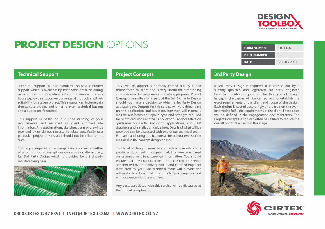
PROJECT DESIGN OPTIONS
Technical Support
Technical support is our standard, no-cost customer support which is available by telephone, email or during sales representative’s routine visits during normal business hours to provide support on our range of products and their suitability for a given project. This support can include data sheets, case studies and other relevant technical backup and a quotation if required.
This support is based on our understanding of your requirements and assumed or client supplied site information. Any specifications, sketches, plans or drawings provided by us do not necessarily relate specifically to a particular project or site, and should not be relied on as such.
Should you require further design assistance we can either offer our in house concept design service or alternatively, full 3rd Party Design which is provided by a 3rd party registered engineer.
Project Concepts
This level of support is normally carried out by our in house technical team and is very useful for establishing concepts used for proposals and costing purposes. Project Concepts can often form part of the full 3rd Party Design should you make a decision to obtain a 3rd Party Design at a later date. Outputs for this service will vary depending on the application and situation, however, will normally include reinforcement layout, type and strength required for reinforced slope and wall applications, anchor selection guidelines for Earth Anchoring applications, and CAD drawings and installation guidelines. Details of what will be provided can be discussed with one of our technical team. For earth anchoring applications a site pullout test is often included in the concept design phase.
This level of design carries no contractual warranty and a producer statement is not provided. This service is based on assumed or client supplied information. You should ensure that any outputs from a Project Concept service are checked by a suitably qualified and certified engineer instructed by you. Our technical team will provide the relevant calculations and drawings to your engineer and will cooperate with the engineer.
Any costs associated with this service will be discussed at the time of acceptance.
3rd Party Design
If 3rd Party Design is required, it is carried out by a suitably qualified and registered 3rd party engineer. Prior to providing a quotation for this type of design, in depth discussion will be carried out to establish the exact requirements of the client and scope of the design. Each design is costed accordingly and based on the work involved to fulfill the requirements of the client. These costs will be defined in the engagement documentation. The Project Concept Design can often be utilised to reduce the overall cost to the client in this stage.

CIRTEX INDUSTRIES LTD
HEAD OFFICE 16 QUEEN STREET, KOPU, THAMES 3578, NEW ZEALANDPOSTAL ADDRESS PO BOX 470, THAMES 3540, NEW ZEALAND
AUCKLAND SALES & DISTRIBUTIONMANUKAU BRANCH 2 WILCO PLACE, WIRI, MANUKAU, AUCKLAND 2104SILVERDALE BRANCH 45 FORGE ROAD, SILVERDALE, AUCKLAND 0932
HAMILTON SALES & DISTRIBUTION28 EMPIRE STREET, FRANKTON, HAMILTON 3204
HASTINGS OFFICE705 ORCHARD ROAD, HASTINGS 4120
WELLINGTON STOCK DISTRIBUTION5-7 MEACHEN STREET, SEAVIEW, WELLINGTON 5010
CHRISTCHURCH SALES & DISTRIBUTIONUNIT 2, 652 HALSWELL JUNCTION ROAD, HORNBY, CHRISTCHURCH 8042
0800 CIRTEX (247 839) I [email protected] I WWW.CIRTEX.CO.NZ
CIRTEX ADVANCED DESIGN SOLUTIONS
DESIGN