trivial change request use case - - / ppts and pdfs/trivial change... · web viewtrivial change...
TRANSCRIPT

In this section, we document the use of integrated tools in the Optimized Lifecycle to process a so-called “Trivial Change Request”. Specifically, we will focus on using the tools introduced in previous sections to accomplish the various tasks associated with this kind of request:
Specifying the business requirements and functional requirements Performing a static (and possibly dynamic) analysis of the impact a proposed
change would have on the application – and upstream/downstream processing Performing the development activities including coding and testing Highlighting the benefits of using the tools over ISPF
Trivial Change Request Use Case
Change Requests can be defined as a call for modifying the behavior of a system due to normal business changes or because there is a bug in the system. A change request needs to go through a software development cycle in which the impact of the considered solution and effort is analyzed and estimated for that change, and then it has to be approved for implementation before work on it can begin. In short, the goal of the Change Request process is to produce a more robust system that better supports the business activities of our customers. Based on the complexity and the effort required to complete a change request, we can term them as trivial or non-trivial. It so happens that most of the time, a change request which we consider trivial, in the end, turns out to be more than being trivial. Here we consider a change request, which is a classic example of one of these scenarios. This section will show how to use the tools and processes of the Optimized Lifecycle to complete the change request successfully.
4.1 Business RequirementThe healthcare business application OnDemandHealth has the logic to compute REIMBURSE-PCT (reimbursement percentage), hardcoded in the programs as literal-based calculations. This logic needs to be changed such that the value for REIMBURSE-PCT is calculated depending on the table values. Note that while most production applications would of course already be variable-based in their computations and algorithms, consider this change a “category” of change request – that would appear to be “trivial” in scope.
4.2 Functional Requirement
At this point, communication with the client is required to understand the business rule that will be applied to compute the value of REIMBURSE-PCT. Once all the clarifications are received, the Functional Requirement document is prepared which would describe in brief the functional modification to the system. An applications, programmer or systems analyst would then document a clear (and probably standardized) statement of modification – similar to the following:“The OnDemandHeath system will be modified to incorporate the calculation of the REIMBURSE-PCT based on the values of the DEDUCTIBLE, COPAYMENT, OOP MAX, COVERAGE LIMITS, and the NETWORK flags.”
IF DEDUCTIBLE > 0 AND COPAYMENT > 0 AND
1

OOP_MAX < 1000 ANDCOVERAGE_LIMITS > 10000 AND IN_NETWORK_REQ = 'Y' AND :IN-OUT-NETWORK = 'Y' MOVE 80 TO REIMBURSE-PCT
ELSEIF (DEDUCTIBLE > 0 AND COPAYMENT = 0) OR (DEDUCTIBLE = 0 AND COPAYMENT > 0) AND
OOP_MAX < 1000 ANDCOVERAGE_LIMITS > 10000COVERAGE_LIMITS > 10000 AND IN_NETWORK_REQ = 'Y' AND :IN-OUT-NETWORK = 'Y' MOVE 60 TO REIMBURSE-PCT
ELSE IF IN_NETWORK_REQ = 'Y' AND :IN-OUT-NETWORK = 'N'
MOVE 40 TO REIMBURSE-PCT ELSE
MOVE 30 TO REIMBURSE-PCT.
The Project Manager or the Project Lead, at this point of time, will open a Work Item in RTCz documenting the approved Change Request and will assign it to the resources required to complete the task.
Figure 15-1 RTCz 2.x Work Item. Note that all of the RTCz work in Chapter 4 was done using RTCz version 2.x. This was only because the version 3.x release of RTCz (as described in Chapter 3) was not available to this team during development.
IMP: Functional Requirement should be reviewed and Signed Off by the clientTraditionally, you would bury this statement of modification in program comments. This practice has led to haphazard business rule – and task management. Instead,
2

we will add this text into the RTCz repository – to govern this entire process, creating persistent and high-value documentation.
4.3 Impact Analysis
Impact Analysis is a very important part of Change Request, which provides an initial insight to the level of complexity and the amount of effort which would be required to achieve the change. Using RAAi, we perform an impact analysis on the variable REIMBURSE-PCT, because this is the data-element whose computational logic is going to be modified.
Impact analysis results shows that there are 3 Source programs and 1 JCL impacted, apart from a number of data-elements, which need to be further analyzed.
Fig 15-2 Impact Analysis results
3

From the RAAi Impact Analysis results, we get a detailed list of all the impacted components in the application. This would help in determining the scope of the Change Request in terms of schedule and effort.
Note: Clearly, in ISPF it not possible to get this kind of impact analysis results. In ISPF we would be manually searching the variable in all the components and deducing the results.
4.4 Change Design
The RAA impact analysis results from Figure 15-2 are taken as input and further analysis is performed to prepare a detailed technical design. Some of the critical points of the design for the above change are discussed here – Note that these next few sections are very detailed and describe procedurally oriented tasks at the software practitioner level.
4.4.1 Stored Procedure
The business logic to compute the patient’s insurance REIMBURSE-PCT (the percentage of a hospital charge covered by the patient’s plan), is the crux for this change. The new logic will be implemented using a DB2 Stored Procedure because of the following reasons:
Using RDz’s Search option, we find that all the variables which determines the value of REIMBURSE-PCT (DEDUCTIBLE, COPAYMENT, OOP MAX, COVERAGE LIMITS, and the NETWORK flag IN-NETWORK-FLAG) are declared in the DCLGEN copybook HLTHPLAN (i.e. available in the DB2 table HEALTH_PLAN)
Figure 15-3 RDz Search option
4

Figure 15-4 Specifying Search attributes for DEDUCTBLE
Figure 15-5 Search results for DEDUCTIBLE displayed
Stored Procedure provides the following advantages:
Reducing the traffic of information across the communication network Splitting the application logic and encouraging an even distribution of the
computational workload Providing an easy way to call a remote program
A new stored procedure will be created using the RDz wizard. The stored procedure PCTPROC will have the following logic:
Input Parameters: PLAN-ID and IN-OUT-NETWORK
Output Parameters: REIMBURSE-PCT and SQLCODE
The Database access component of the new Business logic is as follows:
EXEC SQL SELECT COPAYMENT, COVERAGE_LIMITS, DEDUCTIBLE, IN_NETWORK_REQ, OOP_MAX INTO :COPAYMENT , :COVERAGE-LIMITS , :DEDUCTIBLE , :IN-NETWORK-REQ , :OOP-MAX FROM DDS0001.HEALTH_PLAN WHERE PLAN_ID = :PLANID END-EXEC. IF SQLCODE = +100 MOVE 10 TO REIMBURSEPCT. IF SQLCODE = +0 IF DEDUCTIBLE > 0 AND
COPAYMENT > 0 AND
5

OOP-MAX < 1000 AND COVERAGE-LIMITS > 10000 AND IN-NETWORK-REQ = 'Y' AND INOUTNETWORK = 'Y'
MOVE 80 TO REIMBURSEPCT ELSE
IF (DEDUCTIBLE > 0 AND COPAYMENT = 0) OR (DEDUCTIBLE = 0 AND COPAYMENT > 0) AND
OOP-MAX < 1000 AND COVERAGE-LIMITS > 10000 AND IN-NETWORK-REQ = 'Y' AND INOUTNETWORK = 'Y'
MOVE 60 TO REIMBURSEPCT ELSE IF IN-NETWORK-REQ = 'Y' AND INOUTNETWORK = 'N'
MOVE 40 TO REIMBURSEPCT ELSE
MOVE 30 TO REIMBURSEPCT. MOVE SQLCODE TO W-SQLCODE. MOVE W-SQLCODE TO SQLCODEOUT.
4.4.2 Modification to the Source Modules
Using RAAi Impact Analysis, we had identified which source modules that need modification. In the analysis, it should be ensured that the input parameters to the stored procedure are available in the program.
Using the RAAi (see Section 8.8 of this Redbook) features Program Tree, Control Flow, Data Flow and RAAi Search (Refer Section 8.8) we analyze the source to trace the flow of several values necessary to this apcome up with the following changes to the source modules.
1) Changes to the COBOL program: MSTRUPDT
a) Comment out the existing logic which hard codes the value of REIMBURSE-PCT
b) Code new logic to populate the input parameters to the stored proc is determined as follows:
PLAN-ID -> using the RAAi Integration Search feature looking for modification to PLAN-ID and finding that the PLAN-ID gets its value from the variable INS-IDENT-NBR in the input data set PATINS (Patient Insurance). On double clicking the search result, opens the statement in MSTRUPDT as shown in Figure -
Figure 15-6 Specifying Search attributes for PLAN-ID
6

Figure 15-7 Search results for PLAN-ID displayed
Figure 15-8 Double-clicking the search result opens the component
IN-OUT-NETWORK –> Using RAAi Search option, we find that IN-OUT-NETWORK is one of the values in the input data set PATMSTR (Patient Master).
c) Logic to call to Stored Proc PCTPROC to get the value of REIMBURSE-PCT
d) Logic to call to DB2 error routine in case of a DB2 error
2) PATSRCH and TRMTSRCH
7

Using RAAi, it was found that the input parameter PLAN-ID is not available in the programs PATSRCH and TRMTSRCH. RAA also showed that PLAN-ID is the primary key of the VSAM file and declared in the copybook PATINS – which is used in several other programs. So, apart from the 4 changes mentioned for MSTRUPDT, the additional changes to these programs would be:
a) Include the copybook SQLCA, since both the programs are non-DB2 and now we are changing it into a DB2 Cobol program
b) Include the DCLGEN for the DB2 table HEALTH_PLAN, HLTHPLAN
c) Logic to handle the file PATINS as input to the programs
d) Logic to handle the error in case the PLAN-ID is not found in the input
4.4.3 Modifications to JCLs
RAA also documents which JCL will be affected by the change:
1)REBUILDQThe compile and Link Edit steps for PATSRCH and TRMTSRH will be modified to include the DB2 parameters
2)BNCHMRKQThe PATSRCH and TRMTSRCH steps will be modified to incorporate the PATINS file as input. Also the step will now include a control card or SYSIN card for DB2 parameters
4.4.4 Data Base Administration
We will be creating the Stored Procedure using the Data Perspective in RDz. This will require a set of authorizations that will be provided by the DBAs. To provide DB2 development features, the workbench accesses DB2 system catalog tables. The user ID that the workbench uses must have the following privileges:
CONNECT - to connect to the Database system, in this case it is DB1S CREATE PROCEDURE – to create the stored procedure BINDADD – to create the package CREATEIN privilege on the desired collection ID – to build and install the
stored procedure in the host system. Here the Collection ID is DSS0001C
4.4.5 Test Plan
In the Design phase itself, we prepare the Test Plan (for any change – including trivial changes). in parallel, based on the functional requirement and the design. The test plan ideally contains the entry and exit criteria for the change being implemented. RAAi can also help with the test plan – as it surfaces file and database dependencies for a program.
A sample test case would be:
8

Sl No
Action Involved File/Database Table
Expected Result Actual Result Pass/Fail
1. Run the Stored Procedure PCTPROC with the input as 'GBINS-2FD-T00IX8I-00' for PLAN-ID and ‘Y’ for IN-OUT-NETWORK
HEALTH_PLAN table
The Stored Procedure should return ‘30’ for REIMBURSE-PCT
Table 15-1 Sample Test Case for Stored Proc PCTPROC
IMP: The Design and Test Plan should undergo the review as per the Quality process The Detailed Technical Design Document should be signed-off by client The Test Case document should be signed-off by client
4.5 Development
Once all the necessary signoffs are received and the DBA request for stored procedure authorization has been completed for the development environment, the development of the change is started. Development phase involves coding the changes and then testing them till the exit criteria is satisfied.
4.5.1 Coding
4.5.1.1 Connections required to z/OS when creating the stored procedures
Creating COBOL and PL/I OS/390 stored procedures using RDz requires two connections to z/OS:One connection establishes a link between RDz and the DB2 Universal
Database server on z/OS so that DB2 catalog information about tables, columns, stored procedures, and so on can be displayed and operations (drop, import, sample contents, and so on) on these DB2 assets can be performed. This connection is created using the RDz Data perspective and Data Source Explorer.
The other connection establishes a link between RDz and z/OS so that the generated stored procedure can be stored on and read from z/OS. This connection can be created using the RDz z/OS Systems perspective.
9

Figure 15-9 Data perspective with the z/OS Systems view
4.5.1.2 Tips for creating stored procedures
The following techniques will help you to develop more efficient and useful stored procedures:
Pass all the input data and parameters from the client application to the stored procedure at invocation time.
Return all the result data and output parameters to the client application only when the stored procedure is complete.
Define the input and output parameters in both the client application and the StoredProcedure. The stored procedure must expect the passed parameters.
4.5.1.3 Creating a COBOL stored procedure
To create a COBOL stored procedure, use the Data Project Explorer view of the Data Perspective after creating a new Project and then follow the steps mentioned herewith:
10

Figure 15-10 Creating a new Data Development Project
1. Expand the project and create a new Stored Proc as shown below:
Figure 15-11 Creating a new COBOL Stored Procedure in the Data Project
2. Specify the initial information like Project name, Language and Stored Procedure name. In the Source Location dialog specify the field values as shown:
Figure 15-12 Source Location details for the Stored Procedure
3. Specify the SQL statement that will be used in the Stored Proc
11

Figure 15-13 SQL statement to be used in Stored Procedure
4. Specify the characteristics of the parameter and click Apply for each parameter. When you are finished, click OK. Define the following parameters for the stored procedures to implement our example, as shown in the Table.
Parameter mode Name SQL Type LengthIn PLANID CHAR 20In INOUTNETWORK CHAR 1Out REIMBURSEPCT SMALLINTOut SQLCODEOUT INTEGER
Table 15-2 Input and Output parameters for the Stored Procedure
Tip: Do not enter invalid COBOL names for the parameters. For example, CUST_ID would be accepted when creating the stored procedures parameters, but when the COBOL for a legitimate COBOL variable named: CUST-ID is generated the generated data names will be invalid, since CUST-ID will get transformed to: CUST_ID – and CUST_ID (with an underscore) is an invalid COBOL name. Also do not use invalid DB2 names like CUST-ID. Our suggestion is not to use any special characters as parameter names.
5. When the New COBOL Stored Procedure dialog box opens, click Next. Enter the Collection ID into the entry field. The collection ID is used for binding the package of the stored procedure.
6. Click Advanced. In the z/OS Options window: Enter your WLM environment, for example, DSNAWLM. This is where
the stored procedure will run. The stored procedure will run in the DB2 established stored procedure address space if you do not enter a WLM environment name.
12

Select DB2 for External security. This option specifies how the stored procedure interacts with an external security product, such as RACF®, to control access to non-SQL resources.
Figure 15-14 Specifying WLM environment
7. On the Summary page of New COBOL Stored Procedure window, click Finish. The code is generated. The generated stored procedure source code appears in the Editor view, as shown in Figure 15-15. You must be connected to z/OS, because the code will be generated at the z/OS database.
13

Figure 15-15 COBOL stored procedure generated
8. In the Editor View, select the various tabs, Overview, Parameters, Options, Build, Data sets for Build, and DDL, to ensure that all is according your environment, as shown in Figure
14

Figure 15-16 Stored procedure Options
Some of the options you can change here include:
ASU time limit - Specifies the total amount of processor time, in CPU service units, that a single invocation of a stored procedure can run.
Stay resident - Specifies whether the stored procedure load module is to remain resident in memory when the stored procedure ends.
Commit on return - Indicates whether DB2 commits the transaction immediately on return from the stored procedure.
Build Stored Procedure for Debugging - Select these options to generate the runtime options for debugging.
Runtime options - Language Environment runtime options to control certain aspects of the program processing.
15

Deterministic - Specifies whether the stored procedure returns the same result from successive calls with identical input arguments.
External security - Specifies how the stored procedure interacts with an external security product, such as RACF, to control access to non-SQL resources.
Stored procedure - Indicates whether the stored procedure can execute any SQL statements and, if so, what type. Use the NO SQL option if your stored procedure does not contain SQL statements. The build utility will invoke the SQL statement coprocessor and try to bind a package unless the NO SQL option is set.
9. At this point, we have created COBOL skeleton code in the z/OS system, and now, we modify it according to our design. Note that the COBOL skeleton generated has all the parameters, the linkage section, and the procedure division created according to our input in the pervious windows.
4.5.1.4 Building the COBOL Stored Procedure
Before a stored procedure can be invoked from the DB Servers view or any other calling program, it must be built on the remote system. The process for building the DB2 Stored procedure is as follows:
1. Click the Data sets for Build tab in the Editor view, as shown in Figure on page 340. Check if the values are correct. Some of the options might already have default values, which are obtained from the z/OS Properties. You can change these default property values if needed. Changing the values in these fields does not affect the z/OS build properties. Changing these values affects only the stored procedure build properties.
16

Figure 15-17 Data sets used for stored procedure build
2. Optionally, you can do a Local Syntax Check which might avoid unnecessary compilations at the z/OS database.
3. To build the stored procedure, right-click the stored procedure in the Data Project Explorer view and select Deploy as shown.
Figure 15-18 Deploying the stored procedure
The build utility is now invoked on the remote system and builds the executable form of the stored procedure. This process includes the compilation of the source code, the linkage of the load module, the binding of the DB2 package, and the registration of the stored procedure in the DB2 catalog.
17

The build process is displayed in the SQL Result view with the status “In progress” until it is completed. The status in the SQL Result view changes to “Success” or “Failure” when the build process is completed.
When execution is successful, a short summary of the build process is displayed. If the build process was not successful, information about the failure will be displayed in the SQL Result view. Figure 15-19 shows the successful build of our example.
Figure 15-19 Shows the Deploy was successful
Note: In ISPF, it is a very tedious and complex process to build and deploy a Stored Proc and it requires a dedicated DBA involvement to achieve it. Whereas, using RDz we find that the tool makes the process very easy and time-saving, provided, all the authorization are in place.
4.5.1.5 Code modification to the existing modules
RTCz is used here to do the source control management. After connecting to the Repository and creating a Repository Workspace, we follow the below steps to retrieve the components from Production to do the code modifications:
Create an MVS Subproject in RDz, where the checked-out components will be retrieved to.
Figure 15-20 MVS Subproject created
Switch to the Work Items Perspective and check-out the components to be modified using the ‘Loading zFiles to zOS…’ feature of RTCz.
18

Figure 15-21 Option to Check-Out the components in RTCz
The components MSTRUPDT.cbl, PATSRCH.cbl, TRMTSRCH.cbl, REBUILD.jcl, and BNCHMRK.jcl are selected.
19

Figure 15-22 Selecting components to be checked out
Specify the parameters for Build Definition like the dataset prefixes to be created in the MVS Subproject
20

Figure 15-23 Specifying Build Context
Once the steps in the wizard are completed, the components are checked out to the MVS Subproject specified.
Figure 15-24 Components checked out into the MVS Subproject
MSTRUPDT Cobol Program
1) Declare the new working storage variables to be used.
2) Using the Comment feature of RDz context menu in LPEX Editor, we will comment out the code logic that will be replaced with the new logic, in the paragraphs 3000-CALCULATE-TREATMENT-COSTS, 4000-CALCULATE-EQUIPMENT-COSTS and 1000-GET-PLAN-DATA
21

Figure 15-25 Option to comment out a number of lines together
3) Code the logic to populate the input parameters and the call to stored proc in paragraph with the help of various features available in LPEX Editor like content-assist, real-time error messages, etc discussed in the section 8.4
Figure 15-26 Shows different real-time features in RDz
Here is the sample final code change to the paragraph 3000-CALCULATE-TREATMENT-COSTS.
22

Figure 15-27 Snapshots of the code changes to MSTRUPDT program
Similarly, we do the code changes for the cobol programs PATSRCH, TRMTSRCH and the JCLs REBUILDQ, BNCHMRKQ as per the Design document prepared earlier in the section.
4) On completing the coding and the required reviews, the modified components are checked in to the repository workspace in RTCz using the ‘Pending Changes’ view.
23

Figure 15-28 Code changes in MSTRUPDT being checked in
Note: It is very evident here that the numerous features available in RDz, makes coding a lot more easier and convenient task compared to ISPF. In ISPF, we would not have the options like real-time syntax checks, content assist, commenting a bulk of statements, etc.
IMP:
Update the revision history of the changed module and tag the code changes accordingly as per coding standards specified by the client
All the code changes should be properly reviewed as per the Quality process
4.5.2 Testing
Testing is done with the help of the PD Tools integrated with RDz and Data Perspective, as per the Test Plan prepared during Design phase.
4.5.2.1 Unit Testing
1. Testing Stored Procedure
Using Data Source Explorer view in RDz Data Perspective, we will test run the Stored Procedure PCTPROC, which was build and deployed in the coding phase.
24

Figure 15-29 Running the Stored Procedure
A parameter input panel opens if the stored procedure uses input parameters. Specify the parameter values and click OK
25

Figure 15-30 Input parameters when running the generated stored procedure
When the run completes, information about the run is displayed in the SQL Result view.
Figure 15-31 Messages when running the stored procedure
The results can be seen in the Parameter tab and the Stored Proc PCTPROC successfully returns the value for REIMBURSE-PCT
26
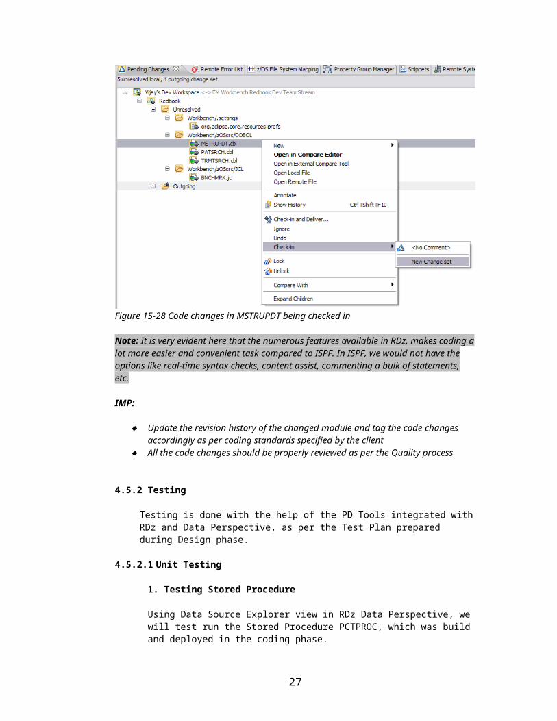
Figure 15-32 Results when running the stored procedure
Note: In ISPF, in order to run a Stored Proc, will require preparation of JCLs with input parameters, which would all be a static process.
2. Preparation of Test Data
Using the RAAi Program Diagram, we find out what data are input to the program and what the output from the program for testing.
Figure 15-33 RAAi Program Diagram view
Using the File Manager features intergrated with RDz, the input data is prepared by allocating the VSAM files and copying test data from the production files:
– Allocate a new VSAM file TEST.PATMASTR with the parameters like the existing PATMASTR production VSAM file
27

Figure 15-34 Using Allocate Like… option to allocate VSAM dataset
Figure 15-35 Using the parameters of an existing VSAM dataset
28

Figure 15-36 Modify any parameter for the target dataset, if required
– Once the VSAM file is created we copy sample data from the production file:
29

Figure 15-37 Copying data to the new VSAM dataset from an existing one
Figure 15-38 Selecting the existing dataset to be copied
30

Figure 15-39 Specifying numbers of records to be copied
– Associate the template with the file created and modify the data, if required, as per our test cases and save it
Figure 15-40 Selecting the Template to be used
Figure 15-41 New VSAM dataset created
31

– Similarly, we allocate and prepare data for other input files: PATINS and PAPERSN VSAM files
– Then the output files required are created (it is always a good idea to use GDGs for output files as we mostly will need to test our job multiple times). There are two GDG output files required by the program: Patient Report (PATRPT) and Patient Error (PATERR) files.
Figure 15-42 Option to create new GDG base in RDz
Figure 15-43 Specifying the parameters for the new GDG base
3. Preparation of JCLs
Modify the Property Group associated with the MVS Subproject ‘Redbook’ with the specific Compile, Link-Edit and Run libraries and parameters.
32

Figure 15-44 Preparing Property Group for the project
Once the Property Group is associated properly, we generate the JCL, needed to Compile, Link-Edit and Run our modified programs
33

Figure 15-45 Generating JCL for Compile Link Go
Figure 15-46 Specifying where the generated JCL will be stored
34

Note: Preparing JCLs, in ISPF, is a manual effort and definitely will require more time than using the automated features in RDz.
4. Running the JCL in Debug Mode
Before running the above job generated for our modified code, we will generate a new job for the production version of the Program MSTRUPDT and run it against the test I/O files. This will create the PATRPT file for the production version of the program – DDS0017.PATRPT.TEST.G0006V00.
Now we run the JCL MSTRUPDT in Debug mode which was created for the modified program. We use Debug mode because of various reasons, of which some major ones are:
We can view the program execution, line-by-line We can verify the value of a variable – during program execution We can stop and start program execution, and analyze results at the speed
that our procedural understanding of the application's execution flow can handle
Figure 15-47 Running the JCL in Debug Mode with various views to help debugging
While debugging, we Step Over the statements that we coded i.e. the call to Stored Proc and computation of REIMBURSE-PCT, and test real-time if the code changes are working properly. Once assured, we resume the job and complete it. Then we check the job spool and the output files to see everything for processed fine.
35

Figure 15-48 JCL run to completion successfully
The job creates the new generation output file PATRPT file: DDS0017.PATRPT.TEST.G0007V00. We can compare this output file with the one created using the production version and check the differences. We know that the difference should only exist in the TOTAL CHARGES field as this is computed using REIMBURSE-PCT whose logic has been changed as part of the the Change Request.
Figure-49 Comparing two GDG versions
36

Figure 15-50 Shows comparison results
Similarly, the test cases for the code changes to the programs PATSRCH and TRMTSRCH are performed using the steps as described above.
Note: Debugging a program, using breakpoints, setting watches and monitors, having the option to see different views simultaneously and various other options, has never been so easy. Using ISPF, it would be very cumbersome task to achieve this.
4.5.2.2 Regression Testing
On ensuring that all the exit-criteria’s for the Unit Testing is a PASS, we do the Regressing testing by running the whole Batch Stream as per the Regression Test Plan. All the steps are verified to see if they ran fine and the outputs reports are created as per the business requirements.
IMP: All the test case results are reviewed to check if all the exit criteria are
satisfied and signed off by the reviewer. The signed off components are migrated to the Test environment using the
process specified by the clients
4.5.2.3 User Acceptance Testing
In most cases, there is a dedicated team which does the user acceptance testing. They prepare their own test cases, perform them and validate them. On successful completion of the UAT, the developer is notified of the results and sign off is given to go ahead with the installation in production. In case of defects during UAT, they are logged in the tool, specified by the client shop and assigned to the developer for being fixed. The developer performs the check out process, fixes the code and checks in back the component for the team to continue the UAT testing.
37