trochanter stabilization plate for dhs implantssynthes.vo.llnwd.net/o16/llnwmb8/us mobile/synthes...
TRANSCRIPT
Extends DHS® Plate Construct to Help Stabilize Greater Trochanter
Trochanter Stabilization Plate for DHS® ImplantsSurgical Technique

Trochanter Stabilization Plate for DHS® Implants Surgical Technique DePuy Synthes 1
Trochanter Stabilization Plate for DHS Implants 2
Indications 2
Surgical Technique 4 Optional Additional Fixation 8
Implant Removal 11
Set List 12
Introduction
Surgical Technique
Product Information
Table of Contents
MR Information The Trochanter Stabilization Plate for DHS System has not been evaluated for safety and compatibility in the MR environment. It has not been tested for heating, migration or image artifact in the MR environment. The safety of the Trochanter Stabilization Plate for DHS System in the MR environment is unknown. Scanning a patient who has this device may result in patient injury.
2 DePuy Synthes Trochanter Stabilization Plate for DHS® Implants Surgical Technique
Trochanter Stabilization Plate for DHS Implants. Extends DHS Plate construct to help stabilize greater trochanter.
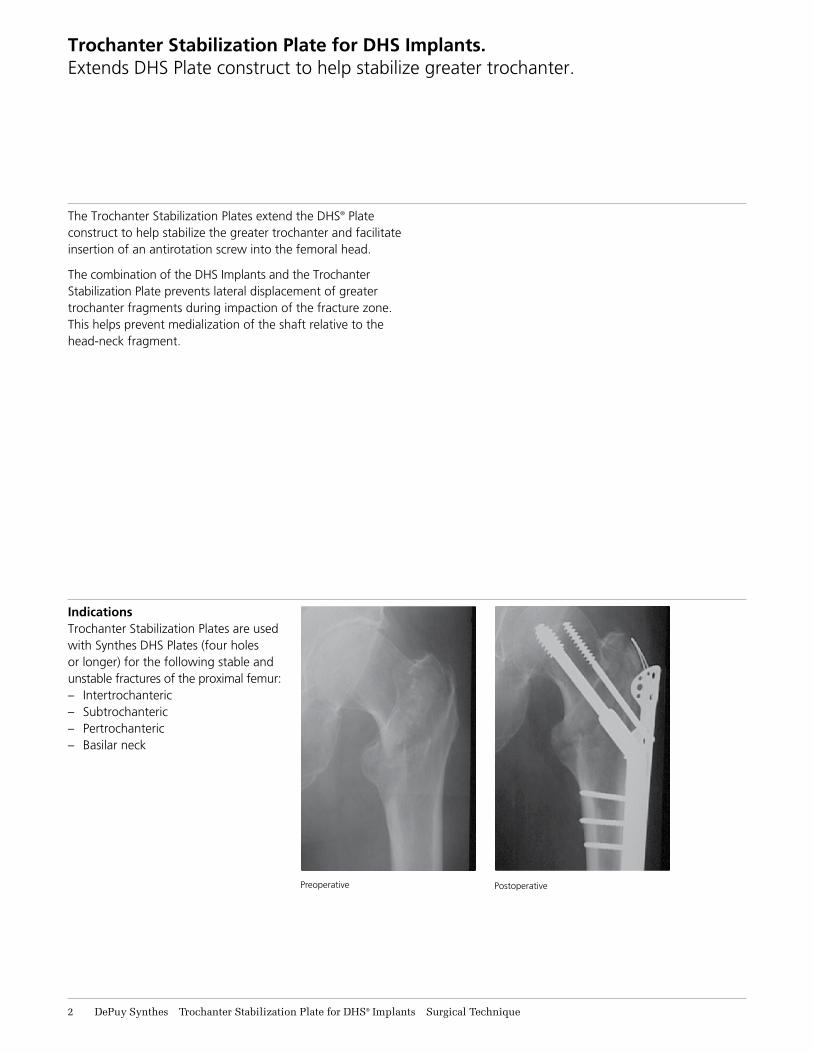
The Trochanter Stabilization Plates extend the DHS® Plate construct to help stabilize the greater trochanter and facilitate insertion of an antirotation screw into the femoral head.
The combination of the DHS Implants and the Trochanter Stabilization Plate prevents lateral displacement of greater trochanter fragments during impaction of the fracture zone. This helps prevent medialization of the shaft relative to the head-neck fragment.
Preoperative Postoperative
IndicationsTrochanter Stabilization Plates are used with Synthes DHS Plates (four holes or longer) for the following stable and unstable fractures of the proximal femur:– Intertrochanteric– Subtrochanteric– Pertrochanteric– Basilar neck
Trochanter Stabilization Plate for DHS® Implants Surgical Technique DePuy Synthes 3
Trochanter Stabilization Plate for DHS Implants. Extends DHS Plate construct to help stabilize greater trochanter.
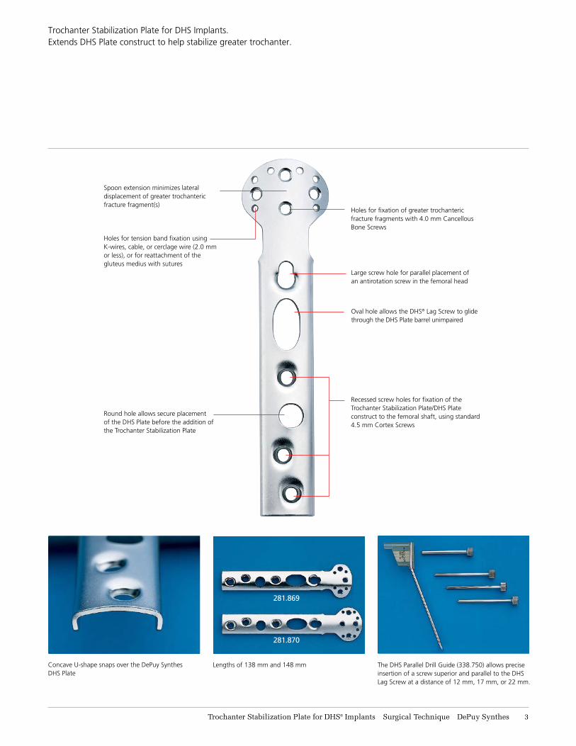
Spoon extension minimizes lateral displacement of greater trochanteric fracture fragment(s)
Holes for tension band fixation using K-wires, cable, or cerclage wire (2.0 mm or less), or for reattachment of the gluteus medius with sutures
Holes for fixation of greater trochanteric fracture fragments with 4.0 mm Cancellous Bone Screws
Round hole allows secure placement of the DHS Plate before the addition of the Trochanter Stabilization Plate
Large screw hole for parallel placement of an antirotation screw in the femoral head
Oval hole allows the DHS® Lag Screw to glide through the DHS Plate barrel unimpaired
Recessed screw holes for fixation of the Trochanter Stabilization Plate/DHS Plate construct to the femoral shaft, using standard 4.5 mm Cortex Screws
Concave U-shape snaps over the DePuy Synthes DHS Plate
The DHS Parallel Drill Guide (338.750) allows precise insertion of a screw superior and parallel to the DHS Lag Screw at a distance of 12 mm, 17 mm, or 22 mm.
Lengths of 138 mm and 148 mm
281.869
281.870

4 DePuy Synthes Trochanter Stabilization Plate for DHS® Implants Surgical Technique
Surgical Technique
Inferior insertion point
Standard insertion point
1Secure DHS Plate
Note: To insert a Trochanter Stabilization Plate and an antirotation screw parallel and superior to the DHS Lag Screw, drill the hole for the lag screw more inferior than normal. This allows room for placement of the antirotation screw superior to the DHS Lag Screw.
Secure the DHS Plate to the femoral shaft with one screw only, through the second-most-proximal DCP® Hole.

Trochanter Stabilization Plate for DHS® Implants Surgical Technique DePuy Synthes 5
2Contour spoon-shaped end
Instrument
329.02* Bending Iron, for 4.5 mm plates
329.30* Plate-Bending Press
391.85 Flat-Nosed Parallel Pliers
Contour the spoon-shaped end of the Trochanter Stabilization Plate to fit the bone, if necessary. The flat-nosed parallel pliers, and the bending iron for 4.5 mm plates, or the plate-bending press may be used to contour the plate.
Surgical Technique
*Also available.
6 DePuy Synthes Trochanter Stabilization Plate for DHS® Implants Surgical Technique
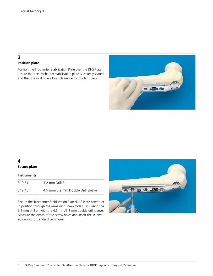
4Secure plate
Instruments
310.31 3.2 mm Drill Bit
312.46 4.5 mm/3.2 mm Double Drill Sleeve
Secure the Trochanter Stabilization Plate/DHS Plate construct in position through the remaining screw holes. Drill using the 3.2 mm drill bit with the 4.5 mm/3.2 mm double drill sleeve. Measure the depth of the screw holes and insert the screws according to standard technique.
Surgical Technique
3Position plate
Position the Trochanter Stabilization Plate over the DHS Plate. Ensure that the trochanter stabilization plate is securely seated and that the oval hole allows clearance for the lag screw.

Trochanter Stabilization Plate for DHS® Implants Surgical Technique DePuy Synthes 7
5Place DHS/DCS® Compression Screw (optional)
If desired, place a DHS/DCS® Compression Screw using standard DHS Dynamic Hip System technique.
Surgical Technique

8 DePuy Synthes Trochanter Stabilization Plate for DHS® Implants Surgical Technique
Surgical Technique
Optional Additional Fixation
Optional fixation methods through the spoon-shaped end of the Trochanter Stabilization Plate include:– 4.0 mm cancellous bone screws– Cerclage wire– Orthopaedic cable– Suture (not shown)
Individual trochanteric fracture fragments may be fixed using 4.0 mm cancellous bone screws through the large holes. A tension band may be constructed using cerclage wire or cable through the small holes. The gluteus medius may be reattached by passing sutures through the small holes.
Fixation with 4.0 mm cancellous bone screws through the large holes
Fixation with cerclage wire through the small holes
Fixation with orthopaedic cable

Trochanter Stabilization Plate for DHS® Implants Surgical Technique DePuy Synthes 9
3Slide DHS Parallel Drill Guide
Instruments
338.740 6.0 mm/4.5 mm Drill Sleeve
338.750 DHS Parallel Drill Guide
Slide the DHS Parallel Drill Guide over the guide wire through the hole marked “0.” Insert the 6.0 mm/4.5 mm drill sleeve into the guide hole marked “12.”
Optional insertion of an antirotation screw using the DHS Parallel Drill Guide
An antirotation screw may be inserted superior and parallel to the DHS Lag Screw. Use one of the following: – 6.5 mm cancellous bone screw– 7.0 mm cannulated screw – 7.3 mm cannulated screw
1Remove DHS/DCS Compression Screw, if necessary
Surgical Technique Optional Additional Fixation
2Reinsert 2.5 mm guide wire through DHS Lag Screw

11 DePuy Synthes Trochanter Stabilization Plate for DHS® Implants Surgical Technique
5Measure and place
The antirotation screw should be measured and placed
according to the appropriate technique.
Surgical Technique Optional Additional Fixation
4Insert appropriate sleeve as indicated below
Antirotation Screw Type Instrument
7.0 mm Cannulated Screw 4.5 mm/2.0 mm Insert Wire Sleeve (388.720*)
6.5 mm Cannulated Bone Screw 4.5 mm/3.2 mm Insert Drill Sleeve (388.730)
7.3 mm Cannulated Screw 4.5 mm/2.8 mm Insert Wire Sleeve (388.731*)
*Also available.

Trochanter Stabilization Plate for DHS® Implants Surgical Technique DePuy Synthes 11
Implant Removal
Remove the implants in the following sequence:
1All fixation elements (screws, wire, cable, suture) attached to the spoon-shaped end of the trochanter stabilization plate (if used)
2Antirotation screw (if used)
3Compression screw (if used)
4 DHS Trochanter Stabilization Plate
5 DHS Plate
6 DHS Lag Screw
Please refer to the DHS/DCS Technique Guide and/or the One-Step DHS/DCS Technique Chart for additional information.

12 DePuy Synthes Trochanter Stabilization Plate for DHS® Implants Surgical Technique
Trochanter Stabilization Plate Instrument and Implant Set (105.385)
Graphic Case690.328 Trochanter Stabilization Plate Instrument
and Implant Set
Instruments338.730 4.5 mm/3.2 mm Insert Drill Sleeve
338.740 6.0 mm/4.5 mm Drill Sleeve
338.750 DHS Parallel Drill Guide
Implants Trochanter Stabilization Plate, 2 ea.
281.869◊ 138 mm
281.870◊ 148 mm
◊ Available nonsterile and sterile-packed. Add “S” to product number for sterile product.
For detailed cleaning and sterilizationinstructions, please refer towww.synthes.com/cleaning-sterilization
or to the below listed inserts which will be included in the shipping container:— Processing DePuy Synthes Reusable Medical Devices—Instruments, Instrument
Trays and Graphic Cases—DJ1305—Processing Non-sterile DePuy Synthes Implants—DJ1304

Trochanter Stabilization Plate for DHS® Implants Surgical Technique DePuy Synthes 13
Also Available
329.02 Bending Iron, for 4.5 mm plates
329.30 Plate-Bending Press
338.720 4.5 mm/2.0 mm Insert Wire Sleeve
338.731 4.5 mm/2.8 mm Insert Wire Sleeve
391.85 Flat Nosed Parallel Pliers
690.344 DHS One-Step Implant Set Graphic Case
690.348 DHS/DCS One-Step Basic Set Graphic Case
Implantation of the Trochanter Stabilization Plate requires one instrument set and one implant set from the following:
105.831 DHS/DCS Basic Set, with self-tapping screws
105.833 DHS/DCS One-Step Basic Set, with self-tapping screws
105.837 DHS Basic Set, with self-tapping screws
105.35 DHS Universal Implant Set
105.352 DHS One-Step Implant Set
105.839 DHS One-Step Basic Set, with self-tapping screws
One or more of the following may be required for optional additional fixation:
105.180 6.5 mm Cannulated Screw Instrument and Implant Set105.07 7.0 mm Cannulated Screw Instrument
and Implant Set
105.185 7.3 mm Cannulated Screw Instrument and Implant Set
105.190 6.5 mm/7.3 mm Combined Cannulated Screw Instrument and Implant Set
105.924 Orthopaedic Cable System Instrument Set
105.118 Basic Screw Set, with self-tapping screws
105.408 Small Fragment Instrument and Implant Set, with self-tapping screws
105.445 Small Fragment Instrument and Implant Set, with self-tapping screws–LC-DCP
105.92 Wire Instrument and Implant Set
298.801.01S 1.7 mm Cable with Crimp, 750 mm, sterile
Recommended power equipment
105.954 Small Battery Drive

© DePuy Synthes 2000–2017. All rights reserved.DSUS/TRM/0916/1060 6/17 DV
Synthes USA, LLC 1101 Synthes AvenueMonument, CO 80132
Manufactured or distributed by:Synthes USA Products, LLC 1302 Wrights Lane EastWest Chester, PA 19380
To order (USA): 800-523-0322 To order (Canada): 855-946-8999
Note: For recognized manufacturer, refer to the product label.
www.depuysynthes.com
Limited Warranty and Disclaimer: DePuy Synthes products are sold with a limited warranty to the original purchaser against defects in workmanship and materials. Any other express or implied warranties, including warranties of merchantability or fitness, are hereby disclaimed.
Please also refer to the package insert(s) or other labeling associated with the devices identified in this surgical technique for additional information.
CAUTION: Federal Law restricts these devices to sale by or on the order of a physician.
Some devices listed in this surgical technique may not have been licensed in accordance with Canadian law and may not be for sale in Canada. Please contact your sales consultant for items approved for sale in Canada.
Not all products may currently be available in all markets.