trojans in wireless sensor networks
TRANSCRIPT

Georgia State University Georgia State University
ScholarWorks @ Georgia State University ScholarWorks @ Georgia State University
Computer Science Theses Department of Computer Science
Fall 12-17-2014
Trojans in Wireless Sensor Networks Trojans in Wireless Sensor Networks
Maryamsadat Jalalitabar
Follow this and additional works at: https://scholarworks.gsu.edu/cs_theses
Recommended Citation Recommended Citation Jalalitabar, Maryamsadat, "Trojans in Wireless Sensor Networks." Thesis, Georgia State University, 2014. https://scholarworks.gsu.edu/cs_theses/78
This Thesis is brought to you for free and open access by the Department of Computer Science at ScholarWorks @ Georgia State University. It has been accepted for inclusion in Computer Science Theses by an authorized administrator of ScholarWorks @ Georgia State University. For more information, please contact [email protected].

TROJANS IN WIRELESS SENSOR NETWORKS
by
MARYAMSADAT JALALITABAR
Under the Direction of Dr.Anu Bourgeois
ABSTRACT
As the demand for cheaper electronic devices has increased, the location of manufactur-
ing foundries has changed to untrusted places outside of the United States. Some of these
locations have limited oversight of the manufacturing of complicated and sensitive electronic
components including integrated circuits (IC). IC, a key component in all current electronic
devices, can be modified to be malicious or to monitor the functions of their applications.
These malicious modifications are called Hardware Trojans. Hardware Trojans can be de-
signed to quietly monitor, to actively send out unencrypted sensitive information, or to

actively destroy their host device. Our research demonstrates the ability of Hardware Tro-
jans to infiltrate a sensor network that could be remotely deployed for various applications.
This research is important due to the dearth of knowledge on the subject. Currently, software
security is given great importance. Our research shows that the same level of importance
must be given to hardware to ensure a trusted and secure environment.
INDEX WORDS: Trojan,Wireless Sensor Networks.
TROJANS IN WIRELESS SENSOR NETWORKS
by
MARYAMSADAT JALALITABAR
A Thesis Submitted in Partial Fulfillment of the Requirements for the Degree of
Master of Science
in the College of Arts and Sciences
Georgia State University
2014

Copyright byMARYAMSADAT JALALITABAR
2014
TROJANS IN WIRELESS SENSOR NETWORKS
by
MARYAMSADAT JALALITABAR
Committee Chair: Dr. Anu Bourgeois
Committee: Dr. Prasad
Dr. Zhu
Electronic Version Approved:
Office of Graduate Studies
College of Arts and Sciences
Georgia State University
December 2014

iv
DEDICATION
This thesis is dedicated to my beloved family whom I am far away from.

v
ACKNOWLEDGEMENTS
This thesis work would not have been possible without the support of many people. I
want to express my gratitude to my advisor Dr. Anu Bourgeois. Also I really appreciate Dr.
Marco Valero’s help and support.

vi
TABLE OF CONTENTS
ACKNOWLEDGEMENTS . . . . . . . . . . . . . . . . . v
LIST OF FIGURES . . . . . . . . . . . . . . . . . . . . vii
LIST OF ABBREVIATIONS . . . . . . . . . . . . . . . . viii
PART 1 INTRODUCTION . . . . . . . . . . . . . . . 1
1.1 Wireless Sensor Network . . . . . . . . . . . . . . . . . . . . . . . . . 1
1.2 Trojans . . . . . . . . . . . . . . . . . . . . . . . . . . . . . . . . . . . . 2
PART 2 SENSOR NODES . . . . . . . . . . . . . . . 5
2.1 WSN in Real World . . . . . . . . . . . . . . . . . . . . . . . . . . . . 6
2.2 TelosB Sensor . . . . . . . . . . . . . . . . . . . . . . . . . . . . . . . . 8
2.3 Mote Characteristics . . . . . . . . . . . . . . . . . . . . . . . . . . . 9
2.4 TinyOS . . . . . . . . . . . . . . . . . . . . . . . . . . . . . . . . . . . . 10
2.5 Radio Communication . . . . . . . . . . . . . . . . . . . . . . . . . . 11
2.6 SPI Bus interface . . . . . . . . . . . . . . . . . . . . . . . . . . . . . 11
PART 3 CC2420 RADIO . . . . . . . . . . . . . . . 13
PART 4 RESULTS . . . . . . . . . . . . . . . . . . 16
4.1 Attacker . . . . . . . . . . . . . . . . . . . . . . . . . . . . . . . . . . . 17
4.1.1 PIR Sensor . . . . . . . . . . . . . . . . . . . . . . . . . . . . . 17
4.1.2 Arduino Uno . . . . . . . . . . . . . . . . . . . . . . . . . . . . 18
4.2 Experiment . . . . . . . . . . . . . . . . . . . . . . . . . . . . . . . . . 19
PART 5 CONCLUSIONS . . . . . . . . . . . . . . . . 22
REFERENCES . . . . . . . . . . . . . . . . . . . . . 23

vii
LIST OF FIGURES
Figure 1.1 Overview of sensor applications. . . . . . . . . . . . . . . . . . . . 2
Figure 2.1 The components of a sensor node. . . . . . . . . . . . . . . . . . . 5
Figure 2.2 System architecture for habitat monitoring. . . . . . . . . . . . . 6
Figure 2.3 Event-triggered activity in the object tracking application. . . . . 7
Figure 2.4 Front and Back of the Tmote Sky module [14]. . . . . . . . . . . . 8
Figure 2.5 SPI bus: single master and single slave . . . . . . . . . . . . . . . 11
Figure 2.6 Block Diagram . . . . . . . . . . . . . . . . . . . . . . . . . . . . 12
Figure 3.1 Microcontroller interface example. . . . . . . . . . . . . . . . . . . 13
Figure 3.2 Telosb CC2420 Radio. . . . . . . . . . . . . . . . . . . . . . . . . 14
Figure 3.3 Tapping the SPI data line. . . . . . . . . . . . . . . . . . . . . . . 15
Figure 4.1 PIR Sensor. . . . . . . . . . . . . . . . . . . . . . . . . . . . . . . 17
Figure 4.2 Arduino Uno. . . . . . . . . . . . . . . . . . . . . . . . . . . . . . 18
Figure 4.3 Pins used for SPI interface on TelosB. . . . . . . . . . . . . . . . 20
Figure 4.4 SPI Interface Configuration. . . . . . . . . . . . . . . . . . . . . . 20
Figure 4.5 Final Implementation. . . . . . . . . . . . . . . . . . . . . . . . . 21

viii
LIST OF ABBREVIATIONS
• GSU - Georgia State University
• CS - Computer Science
• WSN - Wireless Sensor Network
• HT- Hardware Trojan
• IC- Integrated Circuit
• SPI-Serial Peripheral Interface

1
PART 1
INTRODUCTION
1.1 Wireless Sensor Network
In recent years, Wireless Sensor Networks (WSNs) are known all around the world.
These sensor nodes are able to sense, measure, and gather information from the environ-
ment, then based on some local default parameters, they will submit the sensed data to the
user. Due to the limitation in memory and types of deployment areas that are difficult-to-
access, a radio is necessary for wireless communication to transfer the data to a desired base
station . Most of the times there is no infrastructure for a WSN, a number of nodes that
are deployed in the area working together to sense the data.
There are many potential applications for WSNs. In military applications, they are used for
target tracking and surveillance so WSNs can be used for intrusion detection and identifi-
cation [1, 2]. Other examples for use of WSNs is for natural disaster relief [3], biomedical
health monitoring [4, 5], and hazardous environment exploration and seismic sensing [6]. In
the case of natural disasters, one can use nodes to sense and detect the environment in or-
der to forecast events before they happen. In biomedical applications, surgical implants are
useful to watch and monitor a patients health. For seismic sensing, sensor are deployed in a
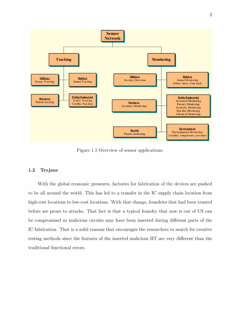
random fashion around the volcano to detect earthquakes and eruptions. Figure 1.1 depicts
the different applications of WSN.
The important features of the wireless sensor networks have enabled many researchers to
work on various issues related to WSN. However, while the routing strategies and energy
harvesting are getting much more attention [7], the hardware security needs more investiga-
tion. We discuss more in details in part 2.
2
Figure 1.1 Overview of sensor applications.
1.2 Trojans
With the global economic pressures, factories for fabrication of the devices are pushed
to be all around the world. This has led to a transfer in the IC supply chain location from
high-cost locations to low-cost locations. With that change, foundries that had been trusted
before are prone to attacks. That fact is that a typical foundry that now is out of US can
be compromised so malicious circuits may have been inserted during different parts of the
IC fabrication. That is a solid reasons that encourages the researchers to search for creative
testing methods since the features of the inserted malicious HT are very different than the
traditional functional errors.

3
Trojans are the malicious altering of hardware specification or implementation in such
a way that its functionality can be modified under a set of conditions defined by the attacker
[8]. Sources of HTs are numerous, some of them are untrusted foundries, tools for
synthesis and verifications tools [9]. Attacks that are caused by an HT can have huge
impact on the security of the IC.
The process of inserting a HT consist of a malicious change to an integrated circuit that
causes some sort of interruption in chip functionality. Trojans are designed to be activated
at some future point. Trojans are hidden cleverly, thus it is highly unlikely that they will be
detected during the validation process.
There are several reasons why standard testing methods are almost useless in detecting
hardware Trojans [10]:
1) Unanticipated behavior is not included in the fault list, structural pattern testing will
likely not cover Trojan test vectors;
2) Additional functionality of genuine designs is difficult to predict without knowledge of
the Trojan inserted by attackers. Hence, routine functional testing is unlikely to reveal
harmful extra functions;
3) Exhaustive input patterns testing is impractical as chips become more complicated with
a large number of primary inputs and inner gates.
In general hardware and software Trojans are in one category. Meaning that the purpose
of both is to lead the user to think a piece of software or hardware is trustable. Then later,
when software is launched or hardware is installed, malicious behaviour of the Trojan will
start. As mentioned earlier, cheaper devices are desired, therefore electronic foundries are
moved to outside of the US. We can not make sure that all of these factories are trustworthy.
We just send them the schematics and plans and we simply trust them to deliver us the

4
desired product. In case of hardware Trojans, there some important features:
• First, it has to be placed physically somewhere on the hardware.
• Second, it has to be triggered to start the malicious behaviour. The triggering mech-
anism can be in form of light, sound, temperature or time.
• Finally, it will be engaged in some type of malicious behaviour such as leaking infor-
mation, draining the battery or recording information.
It is worth mentioning that HT detection is a particularly difficult task in modern and pend-
ing deep submicron technologies due to intrinsic manufacturing variability [8]. Unfortunately,
most of the researcher’s attention is focused on detecting software Trojans, therefore HT has
not been addressed properly.
Moreover there is a lack of knowledge regarding the presence of HT in Wireless Sensor Net-
works. This thesis serves as a proof of concept and will demonstrates the ability of Hardware
Trojans to infiltrate a sensor network that could be remotely deployed for various applica-
tions.
This research is important due to the dearth of knowledge on the subject. As mentioned
earlier, currently, software security is given great importance. Our research shows that the
same level of importance must be given to hardware security to ensure a trusted and secure
environment.
The rest of this thesis is organized as follows: Part 2 discuss more details of the WSN with
regards to this work. Part 3 presents the idea of the HT for this work which helps us in the
design of practical attacks for the purpose of this thesis. Part 4 details the implementation
and testing as the results and finally conclusions are drawn in Part 5.

5
PART 2
SENSOR NODES
In general, wireless sensor networks consist of small nodes also known as motes. A mote
has a number of capabilities which are sensing, computation, and wireless communications.
In most cases, there are hundreds to thousands motes in WSNs. Motes can communicate
among each other or they can talk to a base station directly. These are done via radio
communication. Figure 2.1 illustrates components of a typical mote. As shown in the
picture, nodes are deployed in sensing area in an ad hoc manner. Sensor nodes coordinate
among themselves to produce high-quality information about the physical environment [11].
Figure 2.1 The components of a sensor node.

6
2.1 WSN in Real World
Here we introduce some examples from real world where WSNs were deployed and
adapted.
• Animal population monitoring:
UC Berkely has done a research in order to measure the population and movement pat-
tern of the colonies on the Great Duck Island [12]. To do so, telosB motes has been deployed
in underground burrows and plain-air nests. These sensors detect presence of the animals
due to the change in receiving signals such as photosensing and acoustic ones. Information
about the weather will be collected by humidity and pressure sensors. In this application
telosB motes were deployed in the field and on the upper layer some gateway nodes per-
form the routing task. At the end point, the base station connected to web application will
show the real time information. Figure 2.2 illustrates the tiered system architecture for this
application.
Figure 2.2 System architecture for habitat monitoring.

7
• Intrusion detection on battlefields:
WSNs have a wide range of applications in US military, some of the most important
cases are surveillance, monitoring and detection missions.
Purpose of A Line in The Sand [13] was to accurately detect hostile people and
civilians breaching a certain perimeter. They wanted to classify the people in the groups
of civilians, hostile soldiers and army vehicles. There was an interesting result, by using
magnetic and radar sensor measurements one can distinguish an unarmed person from a
military soldier. Moreover for the tracking purpose of the soldiers, the deployed model was
able to perform the task based on influence field-based algorithms. Security in military fields
is an important issue since the network should be protected and safe after failures. The key
feature of the WSN in this scenario is easy deployment and the reliability with consideration
low cost. A typical operation of the tracking in military application is shown in figure 2.3.
Figure 2.3 Event-triggered activity in the object tracking application.

8
2.2 TelosB Sensor
For this thesis our focus is on the TelosB sensor which has been actively used in many
applications in WSN. Tmote Sky or TelosB is an ultra low power wireless module for use
in sensor networks, monitoring applications, and rapid application prototyping [14]. In
figure 2.4 different parts of the telosB are shown from back and front view.
Figure 2.4 Front and Back of the Tmote Sky module [14].
Some of the most important features of telosB are:
• 250kbps 2.4GHz IEEE 802.15.4 Chipcon Wireless Transceiver
• 8MHz Texas Instruments MSP430 microcontroller (10k RAM, 48k Flash)
• Integrated Humidity, Temperature, and Light sensors
• Ultra low current consumption
• Programming and data collection via USB

9
2.3 Mote Characteristics
There are some features of motes that are needed to be discussed:
• Limited resources: Because of the small size, low cost and low power consumption,
physical resources of the sensors are limited. This limitation is not going to change since the
benefit of these features can not be ignored.
• Reactive Concurrency: Sensors in WSN have a number responsibilities such as in-
formation gathering, performing computations on the sampled data, transmitting data and
routing data to the other sensors. Many of these tasks need real time handling, therefore
a mechanism should be planed to decrease chance of the potential problems regarding the
resources and timing issues.
• Flexibility: WSN has been used in many different scenarios in real world problems,
there is a need for a flexible operating system that can adopt to the application-specific
nature of the WSN. In addition, the OS should support fine-grain modularity and interpo-
sitioning to simplify reuse and innovation[15].
• Low Power: In design process of the sensors size and cost are the key goals. Moreover
battery usage is another important challenge. One solution is energy harvesting but it can
solve the continuous need of the sensors that must operate for a long time. So in the design of
the new operating system for WSN low power operations should be considered and flexibility
in power management should be offered as well.

10
2.4 TinyOS
TinyOS has been introduced as the new operating system that is designed for the sensor
networks which is flexible and application-specific. TinyOS solves the main challenges of the
WSNs, issues like severe memory, event based application and limited resources. TinyOS
solution combines flexible, fine-grain components with an execution model that supports
complex yet safe concurrent operations[15]. TinyOS has been implemented in nesC lan-
guage which is an extension to C that is specificaly designed for the structuring concepts
and execution model of TinyOS.
Major concepts of the nesC are:
• Programs are made of components and ”wiring” term is used for assembling the pro-
grams unit. There are two scopes for each component; one that contains the name of
the interface instances and the other one for the component implementation.
• The function of the component is provided by its interfaces. Each interface can be
provided or be used by the component. The provided ones are for representing the
functionality of the component to its user and the used ones represent the functionality
of that component must be performed as its job.
• Interfaces are used to link different components together, therefore at the run time
efficiency will be increased. Moreover the design will be robust and static analysis of
the program will be easier.
• For better code generation and analysis, in the design of the nesC code are generated
by the whole program compilers.

11
2.5 Radio Communication
Radio communication is an integral component of any wireless distributed system. For
each sensor, there is a low power radio on its board that enables the node to communicate
with other sensors and transmit the sensed data to gateways in the area or directly to the
base station.
On TelosB, the Chipcon CC2420 radio is embedded for wireless communications. With sen-
sitivity exceeding the IEEE 802.15.4 specification and low power operation, the CC2420 pro-
vides reliable wireless communication [16]. So radio communication is done by the CC2420
which is controlled by the TI MSP430 microcontroller through the SPI port.
2.6 SPI Bus interface
Serial Peripheral Interface or simply SPI is a protocol for communication that was
introduced by Motorola. SPI is a simple 4-wire serial bus interface that is used mainly
by microcontroller to establish communication with peripheral devices. The SPI interface
is a full duplex bus meaning that data can be sent in both directions at the same time.
It is a synchronous data link and provides up to 1 megabaud or 10Mbps of speed. In SPI
communication there is always a master and one or more slaves. Master is the one that starts
the communication and controls the communication. Once the connection is established then
data can transmitted on the both sides since the connection is full-duplex. As the peripherals
or slaves there some examples we can consider like memory modules EEPROM and FLASH,
temperature and pressure sensors and UART module. Figure 2.5 shows SPI protocol for
single master and slave.
Figure 2.5 SPI bus: single master and single slave

12
• The standard SPI protocol has 4 signal wires:
1. Master Out Slave In (MOSI) - generated by Master, Slave is the receiver.
2. Master In Slave Out (MISO) - generated by Slave, Master is receiver.
3. Serial Clock (SCK) - Clock signal generated by the Master in order to synchronize data
transfers during the full duplex communication.
4. Slave Select (SS)- most important signal sent by master to Chip Select (CS) pin of
slave.
In case of the telosB that we have used in this project, CC2420 which is the radio on the
TeolosB, uses SPI to communicate to the MSP430 microcontroller as a slave. This is depicted
in figure 2.6 which the block diagram of the MSP430 and its connection to peripherals.
Figure 2.6 Block Diagram

13
PART 3
CC2420 RADIO
In this part we take a deeper look into CC2420 radio that is used on the TelosB. The
CC2420 is a true single-chip 2.4 GHz IEEE 802.15.4 compliant RF transceiver designed for
low power and low voltage wireless applications [17].
ZigBee is a keyword for a set of high level protocols that are used for communication
in order to set up area networks that include low-power radios. ZigBee is based on an IEEE
802.15 standard. IEEE 802.15 is a standard for the physical layer and media access control
for wireless networks that have lower rate. Although these radios are low-power but they
can send data to longer distances by using multihop routing, consequently mesh networks
will be created. Zigbee is appropriate for using in WSN applications in which lower data
rate and longer longevity are desired.
In a typical system such as telosB , CC2420 will be connected to to a microcontroller via
SPI interface. This microcontroller programs CC2420 via the 4-wire SPI bus interface (SI,
SO,SCLK and CSn) as shown in figure 3.1.
Figure 3.1 Microcontroller interface example.

14
As mentioned earlier, CC2420 is IEEE 802.15.4 compliant RF transceiver and on telosB
communication between MSP430 microcontroller and CC2420 is implemented via SPI bus.
There should be a protection mechanism for information that are transmitted via SPI bus,
this is possible via encryption. By using encryption, information should be safe from reading
by a unauthorized third party. This is more important in WSNs where sensors are deployed
and left unattended. The security is built on a secret key. For IEEE 802.15, standard AES-
128 (Advanced Encryption Standard) is used, which has a 128 bit key length encryption.
• Bus Snooping
In this section we investigate an interesting paper [18]. The mote that is used in this
paper is telosB which has the CC2420 as the radio chip. They have explained in the SPI
communication between CC2420 and MSP430 microcontroller AES-128 Keys are sent by
SPI as cleartext. This is a security issue that an attacker can take advantage of the fact that
security keys must be loaded over the SPI bus.
Therefore by snooping the SPI bus and capturing SPI traffic live, an attacker can read the
AES-128 key and later use it for malicious attacks. Figure 3.2 shows a closer look at CC2420
on the telosB mote.
Figure 3.2 Telosb CC2420 Radio.

15
In order to snoop the SPI bus, we have to tap one of the SPI pins of the CC2420 using
oscilloscope probe. As explained earlier SPI has four pins: SCL, MOSI, MISO, and SS. The
Serial Clock or SCL is used as an output from the master to synchronize communication
with the slave. Data lines are MOSI and MISO. Slave Select or SS indicates the selection of
a particular slave chip in this case CC2420. Since we use two probes on the oscilloscope, we
just tap the clock pin SCL and one of the data lines. Tapping the data line is depicted in
figure 3.3.
Figure 3.3 Tapping the SPI data line.
By finding and watching the clock and data lines on the oscilloscope, in order to sniff
the SPI traffic a bus adaptor should be used. All that remains is to identify the key in use,
or anything else sent over the bus, then we have the security key.

16
PART 4
RESULTS
Up to this point we have explained the idea of WSN and Trojans. In part 3 we explained
a security issue of the CC2420. TelosB is widely available and used. This mote can measure
light and temperature. It communicates wirelessly with other sensors via its radio which
is CC2420. In this work, we want to investigate the danger of Trojans in Wireless Sensor
Networks. It is a proof of concept to show the ability of the Trojan to infiltrate a typical
sensor network that could be remotely deployed for various applications.
The main challenge is that we do not have complicated and professional devices to test that
our TelosB boards carry Trojans or not. But the bus snooping that was introduced in the
last chapter inspired us to come up with a new idea.
We make an assumption, we simply suppose that our telosB sensor is carrying a Trojan.
We take advantage of the security issue of the CC2420 by attacking the SPI bus. We try
to inject fake signal via SPI bus in order disrupt radio communication between two telosBs
that are transmitting data. So our challenge is to find a way to attack and interrupt the
communications between the microcontroller and the radio on one of the motes. As soon
as we can disable this communication on the desired motes the mote under attack will stop
communicating with other mote.
The idea is to inject a fake signal to the SPI bus on the telosB to interrupt the
communication between the MSP430 and CC2420.

17
4.1 Attacker
We need to set up a device to generate a fake signal. We call this device the Attacker.
A PIR sensor set up on an Arduino board will be the attacker that we need to generate the
fake signal for us.
4.1.1 PIR Sensor
PIR (Passive Infrared) sensors most of the times are used to detect a human target that
has moved in or out of the sensor range. Every object emits some low level of radiation and
the hotter something is, the more radiation is emitted. PIR sensor is able to detect levels of
infrared radiation. Picture of a PIR sensor is shown in figure 4.1.
Figure 4.1 PIR Sensor.
Most of the PIR sensors have a 3-pin connection at the side or bottom. Two of them
are ground and power and the final one is signal. When the PIR detects motion in its range,
the output pin or signal will go ”high”. We set up the PIR sensor on an Arduino Uno.

18
4.1.2 Arduino Uno
The Arduino Uno is a microcontroller board based on the ATmega328 [19]. It is designed
with 14 pins as digital input/output. Each of these pins can be used either as input or output.
This is possible via functions such as pinMode(), digitalWrite(), and digitalRead() functions.
Arduino Uno is depicted in figure 4.2.
Some of the pins also provide special functions. For SPI communication with other devices
via the SPI library:
• 10 (SS- Slave Select) - the master uses to enable/ disable Slave,
• 11 (MOSI- Master Out Slave In) - Sending data to the peripherals,
• 12 (MISO- Master In Slave Out) - Sending data to the master,
• 13 (SCK - Serial Clock) - Synchronize data transmission generated by the master.
Figure 4.2 Arduino Uno.

19
4.2 Experiment
We want to tap the SPI bus which is the communication interface between the radio
and microcontroller on the TelosB. We set up an attacker to generate a fake signal so we can
use it to tap the SPI bus on telosB. This attacker will be the Arduino along with the PIR
sensor connected to that. As mentioned earlier, PIR sensor is used to detect movement in
its range.
Two telosB motes are running ”RadioCountToLeds” application, each mote will act as a
4Hz counter which broadcasts its counter value each time it gets updated. The other node
that hears a counter as a packet, it then displays the bottom three bits on its LEDs. In this
scenario, radios of the motes are actively involved and wireless communication between the
motes is running via radio and it is visible by the LEDs on the sensor.
On the Arduino board, whenever the PIR sensor detects a motion, there will a high signal
on its output pin. This is what we called fake signal. We want to use it to tap the SPI bus
on the telosB.
As the first part of experiment, we tried to tap the bus using the fake signal directly. It
was not successful and nothing happened after tapping the SPI bus(Motes were still com-
municating and LEDs were blinking). We realized that if we want to tap a SPI bus, a SPI
interface should be set up between the Arduino and the telosB under attack.
Figure 4.3 is taken from telosB datasheet where we marked the pins that are needed for
SPI interface. On the telosB three wires of the SPI 4-Wire protocol are accessed via U2
expansion header. These are SS, MOSI and SCL. The last SPI pin will be directly attached
to MISO pin on the MCU. Next step is two connect the SPI pins on the mote and Arduino
together as explained in figure 4.4 and figure 4.5.

20
Figure 4.3 Pins used for SPI interface on TelosB.
Figure 4.4 SPI Interface Configuration.

21
Figure 4.5 Final Implementation.
On the Arduino, we also use a red LED to visualize the output pin of the PIR sensor,
whenever this pin will be high, LED turns on. Also it should be noted that there is no data
on the MISO pin since we do not send any data from telosB as the slave to Arduino as the
Master.
The most important pin in the SPI communication is SS pin as it tells the telosB that it
has been selected as the Slave. But as soon as we tap the MOSI pin on the telosB the radio
communication stops and the motes can not communicate to each other any more. Similar
case is when we tapped the clock pin and radio communication stops as well but interesting
point is that when we use the CLK pin for tapping, radio communication will resume after
the interruption. This is the result that we were looking for.

22
PART 5
CONCLUSIONS
In recent years wireless sensor networks (WSN) have been used in many important
applications such as remote environmental monitoring and target tracking. This has been
enabled because important features of the sensors in WSN. They are cheap, small and intel-
ligent. Moreover, they are equipped with wireless radio chips which they can use in order to
communicate with each another in the network.
This work was a proof of concept. Our purpose was to show the ability of Hardware Tro-
jans to infiltrate a sensor network that could be remotely deployed for various applications.
We explained the security issue of the telosB mote that has been used widely in WSN. An
attacker can participate in the network and makes some interruption by taking advantages
of the SPI bus that is used for the radio communication on the telosB.
We proved that Hardware Trojans should be taken into consideration as they are an impor-
tant threat to the WSN, especially because motes will be left unattended in the field and it
might be easy for the attackers to access them and by some malicious activities then will be
able to participate in the network. This research is important due to the dearth of knowledge
on the subject. Currently, software security is given great importance. Our research shows
that the same level of importance must be given to hardware to ensure a trusted and secure
environment.
As the future work, we would like to focus on injecting some malicious code or data to
compromise the collected data by a sensor. In this way, we will create a malicious sensing
component. This malicious node can later serve as an internal threat in a deployed WSN.

23
REFERENCES
[1] G. Simon, M. Maroti, A. Ledeczi, G. Balogh, B. Kusy, A. Nadas, G. Pap, J. Sallai,
and K. Frampton, “Sensor network-based countersniper system,” in Proceedings of the
2nd international conference on Embedded networked sensor systems. ACM, 2004, pp.
1–12.
[2] J. Yick, B. Mukherjee, and D. Ghosal, “Analysis of a prediction-based mobility adaptive
tracking algorithm,” in Broadband Networks, 2005. BroadNets 2005. 2nd International
Conference on. IEEE, 2005, pp. 753–760.
[3] M. Castillo-Effer, D. H. Quintela, W. Moreno, R. Jordan, and W. Westhoff, “Wireless
sensor networks for flash-flood alerting,” in Devices, Circuits and Systems, 2004. Pro-
ceedings of the Fifth IEEE International Caracas Conference on, vol. 1. IEEE, 2004,
pp. 142–146.
[4] T. Gao, D. Greenspan, M. Welsh, R. Juang, and A. Alm, “Vital signs monitoring
and patient tracking over a wireless network,” in Engineering in Medicine and Biology
Society, 2005. IEEE-EMBS 2005. 27th Annual International Conference of the. IEEE,
2006, pp. 102–105.
[5] K. Lorincz, D. J. Malan, T. R. Fulford-Jones, A. Nawoj, A. Clavel, V. Shnayder,
G. Mainland, M. Welsh, and S. Moulton, “Sensor networks for emergency response:
challenges and opportunities,” Pervasive Computing, IEEE, vol. 3, no. 4, pp. 16–23,
2004.
[6] G. Werner-Allen, K. Lorincz, M. Ruiz, O. Marcillo, J. Johnson, J. Lees, and M. Welsh,
“Deploying a wireless sensor network on an active volcano,” Internet Computing, IEEE,
vol. 10, no. 2, pp. 18–25, 2006.
[7] W. K. Seah, Z. A. Eu, and H.-P. Tan, “Wireless sensor networks powered by ambi-

24
ent energy harvesting (wsn-heap)-survey and challenges,” in Wireless Communication,
Vehicular Technology, Information Theory and Aerospace & Electronic Systems Tech-
nology, 2009. Wireless VITAE 2009. 1st International Conference on. IEEE, 2009, pp.
1–5.
[8] M. Potkonjak, A. Nahapetian, M. Nelson, and T. Massey, “Hardware trojan horse
detection using gate-level characterization,” in Design Automation Conference, 2009.
DAC’09. 46th ACM/IEEE. IEEE, 2009, pp. 688–693.
[9] X. Zhang, N. Tuzzio, and M. Tehranipoor, “Red team: Design of intelligent hardware
trojans with known defense schemes,” in Computer Design (ICCD), 2011 IEEE 29th
International Conference on. IEEE, 2011, pp. 309–312.
[10] Y. Jin, N. Kupp, and Y. Makris, “Experiences in hardware trojan design and implemen-
tation,” in Hardware-Oriented Security and Trust, 2009. HOST’09. IEEE International
Workshop on. IEEE, 2009, pp. 50–57.
[11] J. N. Al-Karaki and A. E. Kamal, “Routing techniques in wireless sensor networks: a
survey,” Wireless communications, IEEE, vol. 11, no. 6, pp. 6–28, 2004.
[12] A. Mainwaring, D. Culler, J. Polastre, R. Szewczyk, and J. Anderson, “Wireless sensor
networks for habitat monitoring,” in Proceedings of the 1st ACM international workshop
on Wireless sensor networks and applications. ACM, 2002, pp. 88–97.
[13] A. Arora, P. Dutta, S. Bapat, V. Kulathumani, H. Zhang, V. Naik, V. Mittal, H. Cao,
M. Demirbas, M. Gouda et al., “A line in the sand: a wireless sensor network for target
detection, classification, and tracking,” pp. 605–634, 2004.
[14] Advanticsys, “Mtm-cm5000-msp.” [Online]. Available: http://www.advanticsys.com/
shop/mtmcm5000msp-p-14.html
[15] P. Levis, S. Madden, J. Polastre, R. Szewczyk, K. Whitehouse, A. Woo, D. Gay, J. Hill,

25
M. Welsh, E. Brewer et al., “Tinyos: An operating system for sensor networks,” in
Ambient intelligence. Springer, 2005, pp. 115–148.
[16] T. S. D. Sheet, “Moteiv, san francisco, ca, 2006,” 2004.
[17] T. Instruments, “Cc2420: 2.4 ghz ieee 802.15. 4/zigbee-ready rf transceiver,” Available
at Available at http://www. ti. com/lit/gpn/cc2420, 2006.
[18] T. Goodspeed, “Extracting keys from second generation zigbee chips,” Black Hat USA,
2009.
[19] A. DATASHEET, “8-bit avr R© microcontroller with 4/8/16/32k bytes in-system pro-
grammable flash,” 2010.
[20] W. L. Lee, A. Datta, and R. Cardell-Oliver, “Network management in wireless sensor
networks,” Handbook of Mobile Ad Hoc and Pervasive Communications, pp. 1–20, 2006.
[21] A. Pathan, H.-W. Lee, and C. S. Hong, “Security in wireless sensor networks: issues
and challenges,” in Advanced Communication Technology, 2006. ICACT 2006. The 8th
International Conference, vol. 2. IEEE, 2006, pp. 6–pp.
[22] R. Berthier, W. H. Sanders, and H. Khurana, “Intrusion detection for advanced metering
infrastructures: Requirements and architectural directions,” in Smart Grid Communi-
cations (SmartGridComm), 2010 First IEEE International Conference on. IEEE, 2010,
pp. 350–355.
[23] T. Goodspeed, “A side-channel timing attack of the msp430 bsl,” Black Hat USA, 2008.
[24] ——, “Reversing and exploiting wireless sensors,” Arlington, VA, February, 2009.
[25] A. Francillon and C. Castelluccia, “Code injection attacks on harvard-architecture de-
vices,” in Proceedings of the 15th ACM conference on Computer and communications
security. ACM, 2008, pp. 15–26.
[26] J. H. Davies, MSP430 Microcontroller basics. Elsevier, 2008.

26
[27] S. Narasimhan and S. Bhunia, “Hardware trojan detection,” in Introduction to Hardware
Security and Trust. Springer, 2012, pp. 339–364.
[28] Z. Gong and M. X. Makkes, “Hardware trojan side-channels based on physical unclon-
able functions,” in Information Security Theory and Practice. Security and Privacy of
Mobile Devices in Wireless Communication. Springer, 2011, pp. 294–303.
[29] L. Lin, W. Burleson, and C. Paar, “Moles: malicious off-chip leakage enabled by side-
channels,” in Proceedings of the 2009 International Conference on Computer-Aided De-
sign. ACM, 2009, pp. 117–122.
[30] J. Zhang, Y. Tang, S. Hirve, S. Iyer, P. Schaumont, and Y. Yang, “A software-hardware
emulator for sensor networks,” in Sensor, Mesh and Ad Hoc Communications and
Networks (SECON), 2011 8th Annual IEEE Communications Society Conference on.
IEEE, 2011, pp. 440–448.
[31] L. Lin, M. Kasper, T. Guneysu, C. Paar, and W. Burleson, “Trojan side-channels:
Lightweight hardware trojans through side-channel engineering,” in Cryptographic
Hardware and Embedded Systems-CHES 2009. Springer, 2009, pp. 382–395.
[32] R. Karri, J. Rajendran, and K. Rosenfeld, “Trojan taxonomy,” in Introduction to Hard-
ware Security and Trust. Springer, 2012, pp. 325–338.
[33] Z. Chen, X. Guo, R. Nagesh, A. Reddy, M. Gora, and A. Maiti, “Hardware trojan
designs on basys fpga board,” Embedded System Challenge Contest in Cyber Security
Awareness Week-CSAW, vol. 2008, 2008.