troubleshooting and replacement manual - vapor …€¦ · troubleshooting and replacement manual...
TRANSCRIPT

TroubleshootingandReplacementManualGreenMachine™‐CaliforniaRevision 1.5
Vapor Systems Technologies, Inc.650 Pleasant Valley Drive Springboro, OH 45066 (937) 704‐9333 PH (937) 704‐9443 FX www.vsthose.com

VST Green Machine California Troubleshooting Manual
1.5 ‐ CA Troubleshooting and Replacement Parts Manual Page 2 of 67
TableofContents
Table of Contents ............................................................................................................................................... 2
Table of Figures .................................................................................................................................................. 4
This Document ................................................................................................................................................... 5
Green Machine Replacements Parts Table .......................................................................................................... 5
VST Control Panel Replacement Parts List ........................................................................................................... 6
Troubleshooting Flow Chart ............................................................................................................................... 7
1 No Power to the VST Control Panel ............................................................................................................ 9
2 Overfill Alarm ........................................................................................................................................... 18
3 Functionality Test ..................................................................................................................................... 18
3.1 Leak Test .................................................................................................................................................... 21
4 Pressure Sensor ........................................................................................................................................ 26
4.1 Testing Procedures ..................................................................................................................................... 26
5 Control Valves .......................................................................................................................................... 26
5.1 Control Valves Troubleshooting ................................................................................................................. 26
5.2 Valve Core Replacement or Solenoid Replacement .................................................................................... 28 5.2.1 Removing the Valve Solenoid and Core Assembly ................................................................................. 28 5.2.2 Replacing the Valve Solenoid and Core Assembly ................................................................................. 29
6 Vacuum Pump/Motor Assembly Troubleshooting ..................................................................................... 31
6.1 Rubber Flange Sleeve Replacement ........................................................................................................... 31 6.1.1 Removing the Rubber Flange Sleeve ..................................................................................................... 32 6.1.2 Replacing the Rubber Flange Sleeve ...................................................................................................... 32 6.1.3 Vacuum Pump & Motor Assembly Replacement .................................................................................. 33 6.1.4 Replacing the Vacuum Pump Assembly ................................................................................................. 36 6.1.5 Removing the Vacuum Pump ................................................................................................................ 37 6.1.6 Replacing the Vacuum Pump ................................................................................................................. 38
6.2 Vacuum Pump Motor Replacement ........................................................................................................... 39 6.2.1 Removing the Vacuum Pump Motor ..................................................................................................... 39 6.2.2 Replacing the Vacuum Pump Motor ...................................................................................................... 40
7 Introduction to Alarms .............................................................................................................................. 43
7.1 Alarm Overview .......................................................................................................................................... 43
8 ISD Alarms Overview ................................................................................................................................ 44

VST Green Machine California Troubleshooting Manual
1.5 ‐ CA Troubleshooting and Replacement Parts Manual Page 3 of 67
9 Troubleshooting Procedures ..................................................................................................................... 46
9.1 TSP‐001: HC Sentry Loop Light .................................................................................................................. 47
9.2 TSP‐002: HC Sentry RX and TX Lights......................................................................................................... 49
9.3 TSP‐003: PMC Diagnosis‐Display 100% ..................................................................................................... 51
9.4 TSP‐004: PMC Diagnostics ‐ PMC Set‐Up ‐ HC Sensor to MODBUS ........................................................... 52
9.5 TSP‐005: PMC Setup Parameters ............................................................................................................... 55
9.6 TSP‐006: GM Manual RUN Check .............................................................................................................. 56
10 Vapor Filtration Cartridge ......................................................................................................................... 64
11 Vapor Filtration Cartridge Replacement .................................................................................................... 65
11.1 Removing the Vapor Filtration Cartridge ................................................................................................... 66
11.2 Replacing a New Vapor Filtration Cartridge............................................................................................... 67

VST Green Machine California Troubleshooting Manual
1.5 ‐ CA Troubleshooting and Replacement Parts Manual Page 4 of 67
TableofFigures Figure 1: Troubleshooting Flow Chart .......................................................................................................................... 7
Figure 2: VST Control Panel troubleshooting (section 1) .............................................................................................. 8
Figure 3: Electrical Overview Installation Diagram ..................................................................................................... 10
Figure 4: Electrical Field Wiring Diagram ‐ Option 1 ................................................................................................... 11
Figure 5: Electrical Wiring Diagram ‐ Option 2 ........................................................................................................... 12
Figure 6: VST Control Panel Front Cover ..................................................................................................................... 13
Figure 7: VST Control Panel Top ................................................................................................................................. 13
Figure 8: VST Control Panel Inside Front Cover .......................................................................................................... 14
Figure 9: VST Control Panel Components ................................................................................................................... 15
Figure 10: VST Control Panel Disconnect Switch Main Breaker (BRK1) and 115 VAC Power Connections ................ 16
Figure 11: VST Control Panel Green Machine Controller Screen ................................................................................ 16
Figure 12: Sections 2‐5 of Troubleshooting ................................................................................................................ 17
Figure 13: Green Machine Controller Overfill Alarm Screen ...................................................................................... 18
Figure 14: Functionality Test Run Screen ................................................................................................................... 19
Figure 15: Green Machine Operation Diagram ........................................................................................................... 20
Figure 16: Green Machine Vapor Inlet/Return & Air Outlet Connections .................................................................. 24
Figure 17: Leak Check Fixture ..................................................................................................................................... 24
Figure 18: Green Machine Inlet and Outlet ................................................................................................................ 25
Figure 19: Leak Test Screen ........................................................................................................................................ 25
Figure 20: Green Machine Control Valve Layout and Identification .......................................................................... 27
Figure 21: Valve Solenoid Assembly ............................................................................................................................ 28
Figure 22: Valve Assembly .......................................................................................................................................... 29
Figure 23: Vacuum Pump/Motor Assembly troubleshooting (Section 6) ................................................................... 30
Figure 24: Vacuum Pump Coupling Replacement ...................................................................................................... 31
Figure 25: Vacuum Pump Replacement ...................................................................................................................... 33
Figure 26: Vacuum Pump Components Replacement ................................................................................................ 34
Figure 27: Green Machine Junction Box Wiring Diagram ........................................................................................... 41
Figure 28: Vacuum Pump Motor Wiring Diagram ...................................................................................................... 42
Figure 29: TLS‐350 Console ......................................................................................................................................... 43
Figure 30: PMC Set‐up ................................................................................................................................................ 53
Figure 31: ISD Set‐up .................................................................................................................................................. 54
Figure 32: HC Sentry Front View ................................................................................................................................. 57
Figure 33: 24 VDC Power and 4‐20 mA Signal Connections on the HC Sentry Module .............................................. 57
Figure 34: Controller Input / Output Modules Connections ....................................................................................... 58
Figure 35: HC Sentry Field Wiring to the VST Control Panel ....................................................................................... 59
Figure 36: TLS‐350 Inspector Port Communications Installation ................................................................................ 60
Figure 37: TLS‐350 Inspector Port Communications Installation Option B ................................................................. 61
Figure 38: HC Sentry Back View .................................................................................................................................. 62
Figure 39: HC Sentry to the TLS Comm Board Cable Connections .............................................................................. 63
Figure 31: Vapor Filtration Cartridge Replacement .................................................................................................... 65
VST Green Machine California Troubleshooting Manual
1.5 ‐ CA Troubleshooting and Replacement Parts Manual Page 5 of 67
ThisDocument The purpose of this Troubleshooting Guide is to explain what actions to take when the
Green Machine is not functioning properly.
This Guide will cover in detail: 1. An order in which to begin to troubleshoot the Green Machine and VST Control Panel 2. When to replace which components 3. How to replace the necessary components 4. The replacement parts required
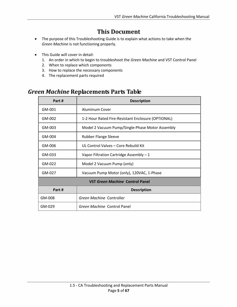
GreenMachineReplacementsPartsTablePart # Description
GM‐001 Aluminum Cover
GM‐002 1‐2 Hour Rated Fire‐Resistant Enclosure (OPTIONAL)
GM‐003 Model 2 Vacuum Pump/Single‐Phase Motor Assembly
GM‐004 Rubber Flange Sleeve
GM‐006 UL Control Valves – Core Rebuild Kit
GM‐033 Vapor Filtration Cartridge Assembly – 1
GM‐022 Model 2 Vacuum Pump (only)
GM‐027 Vacuum Pump Motor (only), 120VAC, 1‐Phase
VST Green Machine Control Panel
Part # Description
GM‐008 Green Machine Controller
GM‐029 Green Machine Control Panel

VST Green Machine California Troubleshooting Manual
1.5 ‐ CA Troubleshooting and Replacement Parts Manual Page 6 of 67
VSTControlPanelReplacementPartsList
Item Qty Part Number Description Manufacturer
1 1 PS3X‐C24AFC 24 VDC POWER SUPPLY, 1.1 A IDEC
2 4 PIR6W‐1P‐24VDC TERMINAL RELAY, 24V AC/DC, SPDT SPRECHER+SCHUH
3 1 KTA7‐25S‐20A 20A MOTOR CIRCUIT CONTROLLER SPRECHER+SCHUH
4 1 KT7‐PA1‐20 SIDE‐MOUNT AUX CONTACT 2 N.O. SPRECHER+SCHUH
5 1 KT7‐UA‐120V UNDERVOLTAGE TRIP MODULE, 120V, CONTROL SPRECHER+SCHUH
6 1 KT7‐HTRY DOOR COUPLING HANDLE, RED/YEL SPRECHER+SCHUH
7 2 KT7‐25‐TE1 TERMINAL ADAPTER SPRECHER+SCHUH
8 1 70S2‐04‐C‐12‐S SOLID STATE RELAY, 12A, 24VDC COIL MAGNECRAFT
9 1 L9‐10/1/D MINI CIRCUIT BREAKER, 10A, UL489 SPRECHER+SCHUH
10 4 V7‐H6 FUSE HOLDER SPRECHER+SCHUH
11 3 MDL‐5 5A GLASS FUSE BUSSMAN
12 1 MDL‐4 4A GLASS FUSE BUSSMAN
13 1 GM‐032 TLS INSPECTOR PORT COMMUNICATIONS KIT VST
14 1 KT7‐HT 250 MM EXTENSION SHAFT SPRECHER & SCHUH
15 1 H721LC ANALOG CURRENT TRANSDUCER VERIS INDUSTRIES

VST Green Machine California Troubleshooting Manual
1.5 ‐ CA Troubleshooting and Replacement Parts Manual Page 7 of 67
TroubleshootingFlowChart
6d
11a
2
6a
6
1b
1c
1d
6b
3
4
5
6c
6e
Figure 1: Troubleshooting Flow Chart

VST Green Machine California Troubleshooting Manual
1.5 ‐ CA Troubleshooting and Replacement Parts Manual Page 8 of 67
Figure 2: VST Control Panel troubleshooting (section 1)
1a 1
1b
1c
1d
1e

VST Green Machine California Troubleshooting Manual
1.5 ‐ CA Troubleshooting and Replacement Parts Manual Page 9 of 67
1 NoPowertotheVSTControlPanelThe VST Control Panels are pre‐wired and tested prior to leaving the factory. There may be a chance that a wire connection came loose during shipment. There is also a chance that the wire connections may not be tight during the field installation or the electrical equipment is not properly configured after the installation wiring is complete. The VST Control Panel is MET Listed to comply with UL Standard 508A, and CSA C22.2 No.14. If an electrical component has malfunctioned inside the VST Control Panel, all the electrical components MUST BE ordered from the Replacement Parts List in this manual.
a. Verify that the breaker for the VST Control Panel in the main power distribution panel is closed. If not, close it.
Verify that the disconnect switch on the front of the VST Control Panel is ON.
b. The Emergency Shut Off (ESO) must supply 115 VAC power to the VST Control Panel for the Green Machine Controller to have 24 VDC power and for the Green Machine to operate.
a. Verify the ESO is not engaged, if the ESO is engaged the Green Machine will not operate. b. Verify the GDF Emergency Shut‐Off (ESO) is connected to the VST Control Panel c. Verify all the wire connections are tight d. Verify the ESO circuit is supplying 115 VAC power to the VST Control Panel across
terminals 02023 and 02032 in the field connections section of the VST Control Panel. See Figure 4.
c. The Safety Disconnect Interlock must be connected to the VST Control Panel for the Green Machine to operate.
a. Check that the Safety Disconnect Switch output voltage is 115VAC. b. Verify the wires to the safety disconnect switch interlock are properly connected to the
VST Control Panel and all the wire connections are correct and tight. c. If a safety disconnect was not installed, a wire jumper must be installed in the VST Control
Panel from: 02023 and 02032, See Figure 4. The interlock wiring or jumper wire must be installed for the Green Machine to operate.
d. Verify the VST Control Panel fuses and wiring to the power supply are correct: a. With power OFF to the VST Control Panel, check to see if the FU 3 fuse is functioning. The
4 amp fuse may be blown, if so replace fuse. See Figure 9. b. Verify there is 24 VDC power out of the 24 VDC power supply. On the 24 VDC power
supply, check the OUTPUT terminals marked –V and +V. The voltage should be 24 ± 5 VDC. The 24 VDC power supply may be damaged, if so replace.
c. Check the 24 VDC wire connections to the Green Machine Controller. At the Green Machine Controller, check to make sure there is 24 VDC power. The Green Machine Controller may be damaged, if so, replace. See Figure 9.
e. If the Control Panel worked prior to this issue and after checking items a‐d, the Control Panel still does not have power, call a VST Technician.
f. If the VST Control Panel does not work on initial install and items a‐d have been checked, call a VST Technician.

VST Green Machine California Troubleshooting Manual
1.5 ‐ CA Troubleshooting and Replacement Parts Manual Page 10 of 67
Figure 3: Electrical Overview Installation Diagram

VST Green Machine California Troubleshooting Manual
1.5 ‐ CA Troubleshooting and Replacement Parts Manual Page 11 of 67
Figure 4: Electrical Field Wiring Diagram ‐ Option 1

VST Green Machine California Troubleshooting Manual
1.5 ‐ CA Troubleshooting and Replacement Parts Manual Page 12 of 67
Figure 5: Electrical Wiring Diagram ‐ Option 2

VST Green Machine California Troubleshooting Manual
1.5 ‐ CA Troubleshooting and Replacement Parts Manual Page 13 of 67
Figure 6: VST Control Panel Front Cover
Figure 7: VST Control Panel Top

VST Green Machine California Troubleshooting Manual
1.5 ‐ CA Troubleshooting and Replacement Parts Manual Page 14 of 67
Figure 8: VST Control Panel Inside Front Cover

VST Green Machine California Troubleshooting Manual
1.5 ‐ CA Troubleshooting and Replacement Parts Manual Page 15 of 67
Figure 9: VST Control Panel Components

VST Green Machine California Troubleshooting Manual
1.5 ‐ CA Troubleshooting and Replacement Parts Manual Page 16 of 67
Figure 10: VST Control Panel Disconnect Switch Main Breaker (BRK1) and 115 VAC Power Connections
Figure 11: VST Control Panel Green Machine Controller Screen

VST Green Machine California Troubleshooting Manual
1.5 ‐ CA Troubleshooting and Replacement Parts Manual Page 17 of 67
Figure 12: Sections 2‐5 of Troubleshooting
2
3
4
5

VST Green Machine California Troubleshooting Manual
1.5 ‐ CA Troubleshooting and Replacement Parts Manual Page 18 of 67
2 OverfillAlarm
After confirming that the Control Panel is working properly, determine if there is input to the Overfill Alarm circuit. If an Overfill Alarm is displayed on the VST controller, then terminal 02044 either has or had +115VDC supplied to it via an external Overfill Alarm relay.
Customer supplied 115 VDC power when the “Fuel Management” Overfill Alarm is active.
Terminal 02044 does not have 115 VDC power after the “Fuel Management” Overfill Alarm clears.
Check to see if the +110VDC is present at the terminal 02044. The Overfill Alarm display will clear 2 hours after the +110VDC signal is removed from the terminal 02044.
See the Electrical Installation section of IOM 18 Green Machine Installation Manual in the latest version of the EO VR 203 or 204 for a description of the wiring of the Overfill Alarm and the Overfill Alarm Screen section for a description of the operation of the Overfill Alarm with the Green Machine.
Once the overfill alarm clears, run a Functionality Test to determine that the Green Machine is functioning normally.
3 FunctionalityTestRun a Functionality Test to verify that the vacuum pump and valves are working properly.
Preparation 1. Put the Green Machine in the Manual OFF mode at the TLS‐350.
2. Push the F5 button to make sure no other tests are running.
3. The Green Machine is now OFF and will not operate.
4. Make sure power is ON to the VST Control Panel.
5. Close the two valves between the Green Machine and the Vent Risers, and remove the caps from both of the tees.
Figure 13: Green Machine Controller Overfill Alarm Screen

VST Green Machine California Troubleshooting Manual
1.5 ‐ CA Troubleshooting and Replacement Parts Manual Page 19 of 67
Testing Procedures
1. Push the F2 button to start the Functionality Test, see Figure 14.
The Green Machine will RUN for 60‐seconds then PURGE for 60‐seconds, (this is one cycle).
The Green Machine will continue to cycle 5‐times or until the F5 button is pushed to end the test.
There are 5‐cycles to provide enough time to conduct the test.
Pushing the F5 button will cancel the test and the screen will show Green Machine OFF.
2. During the 60‐second RUN mode: see Figure 15.
Place your hand over the tee opening at the vapor inlet and feel for suction
Next, place your hand over the tee opening at the air outlet and feel for air blowing
3. During the 60‐second PURGE cycle: see Figure 15.
After the PURGE cycle has begun, place your hand over the tee opening at the vapor inlet and feel for air blowing. The blowing air will reduce to zero flow soon after the PURGE cycle begins.
Next, place your hand over the tee opening at the air outlet and feel for zero airflow.
4. If all the conditions hold true for the above test, the valves and the Vacuum Pump are working as expected.
Figure 14: Functionality Test Run Screen

VST Green Machine California Troubleshooting Manual
1.5 ‐ CA Troubleshooting and Replacement Parts Manual Page 20 of 67
5. Continuous airflow during the PURGE cycle would indicate a leak in the Green Machine internal system:
Push the F5 button to end the Functionality Test and the screen will show Green Machine OFF.
Conduct a Leak Test to find where the leak is occurring.
6. After 5‐cycles are complete, the Functionality Test has ended:
The Green Machine Controller will automatically go back to the Green Machine OFF screen.
Open the two ball valves between the Green Machine and the vent risers, and replace the caps on the two tees.
Put the Green Machine in the AUTOMATIC mode at the TLS‐350.
CAUTION: DO NOT PUT THE GREEN MACHINE IN THE AUTOMATIC MODE AT THE TLS‐350 UNTIL THE VALVES BETWEEN THE GREEN MACHINE AND THE VENT RISERS ARE OPENED. PUTTING THE GREEN MACHINE IN THE MANUAL ON MODE, WHEN THE VALVES ARE CLOSED , WILL NOT ALLOW THE GREEN MACHINE TO OPERATE PROPERLY AND MAY CAUSE DAMAGE TO INTERNAL COMPONENTS.
Figure 15: Green Machine Operation Diagram

VST Green Machine California Troubleshooting Manual
1.5 ‐ CA Troubleshooting and Replacement Parts Manual Page 21 of 67
3.1 LeakTestPurpose and Applicability
The purpose of the Leak Test is to insure that all of the tubing fittings and tubes located inside the VST Green Machine are leak free.
The leak test will be required only at installation, during certain troubleshooting, and any time after the Green Machine plumbing, fittings, or connections have been loosened or adjusted.
Principle and Summary of Test Procedure The Green Machine is configured in the MANUAL OFF operating mode and the solenoid valves
are set such that all internal Green Machine piping and connections can be pressurized with nitrogen. Once pressurized, all piping and connections are checked by applying a soapy solution. Any nitrogen escaping from leaks will cause the soapy solution to bubble. The absence of bubbles indicates that the piping and connections are free of leaks.
Equipment and Supplies Cylinder of compressed nitrogen gas with regulator capable of establishing an outlet flow of less
than 20 psi.
VST Leak Test Fixture (See Figure 17).
Soapy solution that will produce visible bubbles when exposed to nitrogen gas leaking from piping and connections.
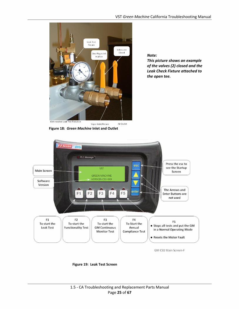
Pre‐Test Requirements Close the manual inlet and outlet valves at the Green Machine, and remove a cap from one of
the tees (See Figure 18). Only one open tee is required for this test.
Install the Leak Test Fixture in the empty 1” pipe tee on the Green Machine as shown in Figure 18.
Ensure that the shut‐off valve on the VST Leak Test Fixture is closed, and then connect the nitrogen source. Set the nitrogen regulator to approximately 5 psi outlet pressure, making sure that it does not exceed a maximum of 20 psi outlet pressure.
Test Procedure
1. Manually turn off the VST Green Machine as follows:
On the TLS Console front panel, use the ‘mode key’ to scroll to ‘DIAG MODE’ and then use the function and step keys to view the ‘VAPOR PROCESSOR MODE’ menu.
2. From the ‘VAPOR PROCESSOR MODE’ menu, change the vapor processor mode of operation from automatic to manual mode. From the ‘VAPOR PROCESSOR STATE’ menu, verify the VP STATE is in the “off” mode. The processor shall be in the off mode for the duration of the test.

VST Green Machine California Troubleshooting Manual
1.5 ‐ CA Troubleshooting and Replacement Parts Manual Page 22 of 67
CAUTION: If by chance the TLS is in the Auto Mode during the Leak Check Test, the PLC, after the F1 button is pushed, will control the Green Machine as indicated in Step 1 above. After the F5 button is pushed or the 30‐minute timer times out, the PLC will convert back to a Normal Operating Mode and the Green Machine will start automatically if the UST pressure is above + 0.2”WC. Since this test is conducted with either the Green Machine inlet and outlet valve closed, starting the Green Machine automatically will NOT ALLOW THE GREEN MACHINE TO OPERATE PROPERLY AND MAY CAUSE DAMAGE TO INTERNAL EQUIPMENT.
3. Make sure power is ON to the VST Control Panel.
4. At the VST Control Panel (See Figure 19), press the F1 button to disable running the vacuum pump and to open all of the control valves. The vacuum pump will remain off until one of the following conditions is met:
o The F5 button is pushed OR o The PLC internal timer times out at 30 minutes
If additional time is needed to conduct the Leak Test, push the F1 button again to re‐start the 30 minute timer.
5. Slowly and carefully pressurize the Green Machine to between 1.0 and 2.0 psi as follows:
Make sure the shut‐off valve on the Leak Test Fixture is fully closed.
Make sure the Leak Test Fixture pressure regulator is fully closed.
Slowly open the valve on the test fixture to pressurize the Green Machine at 1.0 to 2.0 PSI nitrogen.
CAUTION: PRESSURIZING THE Green Machine OVER A MAXIMUM OF 5.0 PSI MAY CAUSE DAMAGE TO THE Green Machine O‐RINGS AND/OR PUMP SEALS, WHICH WILL VOID ALL WARRANTIES OF THE Green Machine.
6. With the Green Machine pressurized between 1.0 to 2.0 PSI nitrogen, spray a soapy solution on each fitting to check for bubbles:
If bubbles do not appear, the connection is tight.
If bubbles do appear, tighten the leaking fitting 1/8” turn (maximum) and re‐check for leaks.
If the fitting cannot be tightened so that the connection is leak free, replace the 45° flare tube assembly that is leaking with a new tube assembly.
7. Continue this process until all the internal tube fittings have been checked and found leak free.
8. Once this test is complete and all the piping fittings are leak free, remove the compressed nitrogen connection to the Leak Test Fixture.

VST Green Machine California Troubleshooting Manual
1.5 ‐ CA Troubleshooting and Replacement Parts Manual Page 23 of 67
9. Remove the Leak Test Fixture and Re‐install the 1” pipe plug.
10. Open the manual inlet and outlet valves at the Green Machine.
11. After the testing is completed, push the F5 button on the VST Control Panel to put the PLC back to normal operating mode. If the F5 button is not pushed, the PLC will convert back to normal operating mode 30 minutes after the F1 button was pushed.
12. Use the TLS‐350 to put the Green Machine back into the Automatic mode.

VST Green Machine California Troubleshooting Manual
1.5 ‐ CA Troubleshooting and Replacement Parts Manual Page 24 of 67
Figure 16: Green Machine Vapor Inlet/Return & Air Outlet Connections
Figure 17: Leak Check Fixture
VST Green Machine California Troubleshooting Manual
1.5 ‐ CA Troubleshooting and Replacement Parts Manual Page 25 of 67
Note: This picture shows an example of the valves (2) closed and the Leak Check Fixture attached to the open tee.
Figure 18: Green Machine Inlet and Outlet
Figure 19: Leak Test Screen

VST Green Machine California Troubleshooting Manual
1.5 ‐ CA Troubleshooting and Replacement Parts Manual Page 26 of 67
4 PressureSensorIf the Green Machine is not turning on and steps 1‐3 have been verified to be functioning properly, check the accuracy of the pressure sensor with the Green Machine Controller to make sure that the Pressure Sensor is working properly.
4.1 TestingProcedures
1. Connect the device that will be used to measure the pressure to the UST at the Vapor Poppet or other suitable location (Green Machine inlet tee or the dispenser vapor piping).
2. Check the TLS‐350 and confirm that the reading on the measuring device and the TLS‐350 are comparable.
3. If readings are close, the pressure sensor is working. If not, replace the pressure sensor per the Veeder Root replacement procedures.
5 ControlValves
5.1 ControlValvesTroubleshooting
1. Check for a magnetic field at the red cap in the center of the valve during a Functionality Test. a. Take a small non‐magnetized screwdriver that will be drawn to the magnetic field, if one
is present, and see if the screwdriver is drawn to the general location of the red cap. b. The valves will alternate as the Green Machine switches between Run and Purge cycles.
During the Run cycle, control valves A, C and E will be ON and B and D will be OFF. c. During the Purge cycle, control valves B and D will be ON and A, C and E will be OFF.
See Figure 20. 1. If while running the Functionality Test during the RUN Cycle there is NO suction
on the vapor inlet/return opening OR air is NOT blowing out of the air outlet opening:
a. And there is 115 VAC to FU1 then, replace the solenoids on valves A and C.
b. And if there is 115 VAC to FU4, then replace the solenoid on valve E.
2. If there is no magnetic field, check the wiring for voltage. a. If voltage is present, replace solenoid. b. If no voltage is present, troubleshoot wiring back to the Green Machine Control Panel.
NOTE: Follow Lockout Tagout procedures if replacing the solenoid.
3. If the magnetic fields are present, listen for any of the valves making a chattering sound. If chattering is heard, replace the valve assembly with VST P/N GM‐006. See Figures 21 and 22.

VST Green Machine California Troubleshooting Manual
1.5 ‐ CA Troubleshooting and Replacement Parts Manual Page 27 of 67
Figure 20: Green Machine Control Valve Layout and Identification

VST Green Machine California Troubleshooting Manual
1.5 ‐ CA Troubleshooting and Replacement Parts Manual Page 28 of 67
5.2 ValveCoreReplacementorSolenoidReplacement
5.2.1 RemovingtheValveSolenoidandCoreAssembly
See Figure 21
1. Disconnect power to the VST Control Panel. (The power, ground, and neutral will be completely disconnected from the Green Machine.)
2. Follow lockout & tagout procedures
3. Unlock the hasps and remove the cover from the Green Machine.
4. Un‐lock and close the ball valves between the Green Machine and the vent risers
NOTE: The Liquid Tight conduit or fitting does not have to be removed from the solenoid
5. Remove the red cap from the solenoid.
6. Remove the nameplate by pushing the solenoid down towards the valve body, then lift and slide the nameplate off.
7. Slide the solenoid off the solenoid base. DO NOT lose the spring washer located below the solenoid on the solenoid base.
8. Using a ¾” wrench, remove the solenoid base from the valve body, the core assembly with core spring, and the body gasket, and discard.
Figure 21: Valve Solenoid Assembly

VST Green Machine California Troubleshooting Manual
1.5 ‐ CA Troubleshooting and Replacement Parts Manual Page 29 of 67
5.2.2 ReplacingtheValveSolenoidandCoreAssembly
See Figure 22
1. Install a new Core Assembly which includes:
Solenoid base
Core assembly with core spring
Body gasket 2. Screw the solenoid base assembly
onto the valve body and tighten with a ¾” wrench until tight. Make sure to install the body gasket with the solenoid base.
3. Place the spring washer on the solenoid base, then slide the solenoid on to the solenoid base.
4. Slide and lock the nameplate on the solenoid.
5. Snap the red cap on the solenoid.
6. Open the ball valves between the Green Machine and the vent risers and lock in the OPEN position.
7. CAUTION: BOTH BALL VALVES BETWEEN THE GREEN MACHINE AND THE VENT RISERS MUST BE OPEN BEFORE APPLYING POWER TO THE VST CONTROL PANEL TO AVOID DAMAGE TO THE GREEN MACHINE INTERNAL EQUIPMENT.
8. Put the cover on the Green Machine and lock the hasps.
9. Remove the lock(s) and tags from the lockout & tagout.
10. After the work is completed, turn ON power to the VST Control Panel. The Green Machine is now operational
Figure 22: Valve Assembly

VST Green Machine California Troubleshooting Manual
1.5 ‐ CA Troubleshooting and Replacement Parts Manual Page 30 of 67
6
6b
6c
6d
6a
6e
6e
Figure 23: Vacuum Pump/Motor Assembly troubleshooting (Section 6)

VST Green Machine California Troubleshooting Manual
1.5 ‐ CA Troubleshooting and Replacement Parts Manual Page 31 of 67
6 VacuumPump/MotorAssemblyTroubleshooting
a. Verify that vacuum pump/motor assembly rotates freely. Visually inspect the Rubber Flange Sleeve if not intact, replace. Run Functionality Test again.
b. If the Functionality Test fails again, verify the vacuum pump breaker BKR2 inside the VST Control Panel is not tripped. See Figure 9.
If the Control Panel is tripped, reset the breaker and check to see if the Vacuum Pump/Motor is working by running a Functionality Test.
c. Verify the wiring of the vacuum pump/motor assembly is not damaged.
d. Verify the vacuum pump/motor wiring is tight and correct, even at the motor junction box.
e. If the vacuum pump/motor assembly rotates freely and steps 1‐4 have been verified to be functioning properly, replace the vacuum pump/motor assembly as outlined in the replacement section.
6.1 RubberFlangeSleeveReplacementNOTE: The Rubber Flange Sleeve replacement is done with the motor still attached to the Green Machine base.
Safety
Use lockout / tagout procedures prior to starting work.
Figure 24: Vacuum Pump Coupling Replacement

VST Green Machine California Troubleshooting Manual
1.5 ‐ CA Troubleshooting and Replacement Parts Manual Page 32 of 67
6.1.1 RemovingtheRubberFlangeSleeve
See Figure 24
1. Disconnect power to the VST Control Panel. (The power, ground, and neutral will be completely disconnected from the Green Machine).
2. Follow lockout & tagout procedures.
3. Unlock the hasps and remove the cover from the Green Machine NOTE: The Vacuum Pump and tubing will not be affected by moving the vacuum pump motor.
4. Remove the Fan Guard over the Coupling Flanges.
5. Remove 4 vacuum pump motor mounting bolts from the base plate.
6. Without removing the electrical service from the vacuum pump motor, slide the vacuum pump motor away from the Vacuum Pump so the Rubber Flange Sleeve can be removed.
6.1.2 ReplacingtheRubberFlangeSleeve
See Figure 24
1. Insert a new coupling sleeve and slide the vacuum pump motor towards the Vacuum Pump so the sleeve is tight between the coupling flanges.
2. Re‐install and tighten the 4 vacuum pump motor mounting bolts to the base plate.
3. Re‐install the fan guard over the coupling flanges.
4. Remove the lock(s) and tags from the lockout & tagout.
5. After the work is completed, turn ON power to the VST Control Panel. The Green Machine is now operational.
6. At the Green Machine, check to make sure the Vacuum Pump and vacuum pump motor are running without excessive vibration or noise.
7. Put the cover on the Green Machine and lock the hasps.

VST Green Machine California Troubleshooting Manual
1.5 ‐ CA Troubleshooting and Replacement Parts Manual Page 33 of 67
6.1.3 VacuumPump&MotorAssemblyReplacement
Safety
Use lockout / tagout procedures prior to starting work.
Figure 25: Vacuum Pump Replacement

VST Green Machine California Troubleshooting Manual
1.5 ‐ CA Troubleshooting and Replacement Parts Manual Page 34 of 67
Figure 26: Vacuum Pump Components Replacement

VST Green Machine California Troubleshooting Manual
1.5 ‐ CA Troubleshooting and Replacement Parts Manual Page 35 of 67
6.1.3.1 Removing the Vacuum Pump Assembly
See Figures 25‐28
1. Disconnect power to the VST Control Panel. (The power, ground, and neutral will be completely disconnected from the Green Machine).
2. Follow lockout & tagout procedures.
3. Unlock the hasps and remove the cover from the Green Machine.
4. Remove the Vacuum Pump ½” inlet 45º flare tubing and all pipe fittings connected to the vacuum pump.
CAUTION: The tube ends are a Parker 45º flare; use caution not to damage the flared ends on the tubing or the threads on the nuts after removal.
5. Disconnect and remove the Vacuum Pump Motor electrical inside the Internal Junction Box.
See Figures 28
6. Remove the 4 mounting bolts holding the Vacuum Pump and Motor Assembly to the Green Machine base plate. The Vacuum Pump and Motor Assembly will stay connected to the base plate. Keep the 4 bolts for reuse.
7. Remove the Vacuum Pump and Motor Assembly.

VST Green Machine California Troubleshooting Manual
1.5 ‐ CA Troubleshooting and Replacement Parts Manual Page 36 of 67
6.1.4 ReplacingtheVacuumPumpAssembly
See Figures 25 ‐ 28
1. Place the new Vacuum Pump on the Green Machine base and align the mounting holes.
2. Re‐install the (4) ¼” x 1‐½” Vacuum Pump Assembly mounting bolts.
3. Tighten the mounting bolts so that the bottom of the Vacuum Pump Base is ⅛” from the Green Machine base.
4. Re‐install the ½” inlet/outlet 45º flare tubing and all pipe fittings connected to the Vacuum Pump
Do not use any thread sealing compound when assembling the 45 º flare nuts.
CAUTION: When tightening the 45° flare nuts: Clamp the tube flare between nut and nose body of the tube by screwing the nut on finger tight. Tighten with a wrench an additional ¼ turn for a metal‐to‐metal seal.
5. Reconnect the Vacuum Pump Motor electrical power wires inside the Internal Junction Box. See Figure 28.
6. Remove the lock(s) and tags from the lockout & tagout.
7. After the work is completed, turn ON power to the VST Control Panel. The Green Machine is now operational.
8. Perform a Leak Test to make sure all the tube fittings are leak tight.
9. When performing the Leak Test, check to make sure the Vacuum Pump and Motor are running without excessive vibration or noise.
10. Put the cover on the Green Machine and lock the hasps.

VST Green Machine California Troubleshooting Manual
1.5 ‐ CA Troubleshooting and Replacement Parts Manual Page 37 of 67
6.1.5 RemovingtheVacuumPump
See Figures 25 ‐ 28
1. Disconnect power to the VST Control Panel. (The power, ground, and neutral will be completely disconnected from the Green Machine).
2. Follow lockout & tagout procedures.
3. Unlock the hasps and remove the cover from the Green Machine NOTE: The Motor will not be affected during the removal and replacement of the Vacuum Pump.
4. Remove the Vacuum Pump ½” 45º flare tubing and all pipe fittings connected to the Vacuum Pump and save for reuse.
CAUTION: The tube ends are a Parker 45º flare, use caution not to damage the flared ends on the tubing or the threads on the nuts after removal.
5. Remove both the fan guards for access to the coupling flanges and removal of the Vacuum Pump.
6. Remove the 4 mounting bolts from the Vacuum Pump Base and keep for reuse.
7. Slide the Vacuum Pump away from the Motor and remove.
CAUTION: There may be metal shims under the Vacuum Pump. They must be marked for location and saved for reuse.
8. The Rubber Coupling between the Vacuum Pump and the Motor may, at the discretion of the contractor, be replaced if worn.
9. Remove the Vacuum Pump Drive‐Coupling Flange from the Vacuum Pump Shaft and keep for reuse. The flange is attached to the shaft with 2 set screws.

VST Green Machine California Troubleshooting Manual
1.5 ‐ CA Troubleshooting and Replacement Parts Manual Page 38 of 67
6.1.6 ReplacingtheVacuumPump
See Figures 25 ‐ 28
1. Re‐install the Drive‐Coupling Flange on the Vacuum Pump shaft but do not tighten the set screws.
2. Place the new Vacuum Pump on the base and align the mounting holes. Remember to re‐install the shims under the Vacuum Pump.
3. Install the rubber insert between the Motor Flange and the Pump Flange.
4. Reinstall and tighten the 4 Vacuum Pump mounting bolts.
5. Slide the drive‐coupling flange over the rubber insert so both halves of the coupling are tight against the rubber insert and tighten the set screws.
6. Re‐install the ½” inlet/outlet 45° flare tubing and all pipe fittings connected to the Vacuum Pump.
CAUTION: Do not use any thread sealing compound when assembling the 45 º flare nuts. CAUTION: When tightening the 45° flare nuts: Clamp the tube flare between nut and nose body of the tube by screwing the nut on finger tight. Tighten with a wrench an additional ¼ turn for a metal‐to‐metal seal.
7. Re‐install both the fan guards.
8. Remove the lock(s) and tags from the lockout & tagout.
9. After the work is completed, turn ON power to the VST Control Panel. The Green Machine is now operational.
10. Perform a Leak Test to make sure all the tube fittings are leak tight.
11. When performing the Leak Test, check to make sure the Vacuum Pump and motor are running without excessive vibration or noise.
12. Put the cover on the Green Machine and lock the hasps.

VST Green Machine California Troubleshooting Manual
1.5 ‐ CA Troubleshooting and Replacement Parts Manual Page 39 of 67
6.2 VacuumPumpMotorReplacement
6.2.1 RemovingtheVacuumPumpMotor
See Figures 25 ‐ 28
1. Disconnect power to the VST Control Panel. (The power, ground, and neutral will be completely disconnected from the Green Machine).
2. Follow lockout & tagout procedures.
3. Unlock the hasps and remove the cover from the Green Machine
NOTE: The Vacuum Pump and tubing will not be affected by removing the motor.
4. Remove the fan guard over the Drive‐Coupling Flanges.
5. Disconnect the motor wires inside the Motor Junction Box. See Figure 28: Green Machine Vacuum Pump Motor Wiring Diagram
6. Remove the flexible conduit and 90° Liquid Tight fitting from the vacuum pump motor junction box and keep for reuse.
7. Remove 4 vacuum pump motor mounting bolts from the Motor Base and keep for re‐use.
8. Slide the vacuum pump motor away from the Vacuum Pump and remove.
9. The rubber sleeve between the Vacuum Pump and vacuum pump motor Flanges may, at the discretion of the contractor, be replaced if worn.
10. Remove the vacuum pump motor drive‐coupling Flange from the motor shaft and keep for reuse. The coupling is attached to the shaft with a setscrew and has a shaft key.

VST Green Machine California Troubleshooting Manual
1.5 ‐ CA Troubleshooting and Replacement Parts Manual Page 40 of 67
6.2.2 ReplacingtheVacuumPumpMotor
See Figures 25 ‐ 28
1. Re‐install the Drive‐Coupling Flange on the Motor Shaft but do not tighten the set screw and do not install the shaft key.
2. Place the vacuum pump motor on the base, install the rubber sleeve between the two Coupling Flanges, and align the mounting holes.
3. Re‐install and tighten the 4 vacuum pump motor mounting bolts.
4. Slide the Drive‐Coupling Flange over the rubber insert so both halves of the coupling are tight against the rubber insert.
5. Install the shaft key, and tighten the set screw.
6. Install the 90° Liquid Tight fitting and flexible conduit on the Motor Junction Box.
7. Re‐connect the vacuum pump motor wires inside the Motor Junction Box See Figure 28: Green Machine Vacuum Pump Motor Wiring Diagram
8. Re‐install the fan guard.
9. Remove the lock(s) and tags from the lockout & tagout.
10. After the work is completed, turn ON power to the VST Control Panel. The Green Machine is now operational.
11. At the Green Machine, check to make sure the Vacuum Pump and vacuum pump Motor are running without excessive vibration or noise.
12. Put the cover on the Green Machine and lock the hasps.

VST Green Machine California Troubleshooting Manual
1.5 ‐ CA Troubleshooting and Replacement Parts Manual Page 41 of 67
Figure 27: Green Machine Junction Box Wiring Diagram

VST Green Machine California Troubleshooting Manual
1.5 ‐ CA Troubleshooting and Replacement Parts Manual Page 42 of 67
Figure 28: Vacuum Pump Motor Wiring Diagram

VST Green Machine California Troubleshooting Manual
1.5 ‐ CA Troubleshooting and Replacement Parts Manual Page 43 of 67
7 IntroductiontoAlarms Sites will use either PMC software or ISD software.
Reference materials required are:
A copy of the Executive Order VR‐203/204 (with all the Exhibits and IOM manuals)
7.1 AlarmOverviewThe front panel of the TLS‐350 has three lights:
1. Red = Failure Alarm 2. Yellow = Warning Alarm 3. Green = Power
The TLS console is continuously monitoring the vapor‐recovery system for alarm conditions.
During normal operation when the EVR system is functioning properly and no alarm conditions exist, the “ALL FUNCTIONS NORMAL” message will appear in the system status line of the console display, and the green power light will be the only light ON.
If an alarm condition occurs, the system displays the condition type and its location. Warning and Failure alarm postings cause the TLS console to activate a warning or a failure indicator light, an audible alarm, and an automatic printout that documents the warning or alarm.
If more than one condition exists, the display will continuously cycle through the appropriate alarm messages.
Historical reports of warning and alarm events are available for up to one year with ISD only.
The system automatically prints an alarm report showing the alarm type, its location, and the date and time the alarm condition occurred.
Figure 29: TLS‐350 Console
VST Green Machine California Troubleshooting Manual
1.5 ‐ CA Troubleshooting and Replacement Parts Manual Page 44 of 67
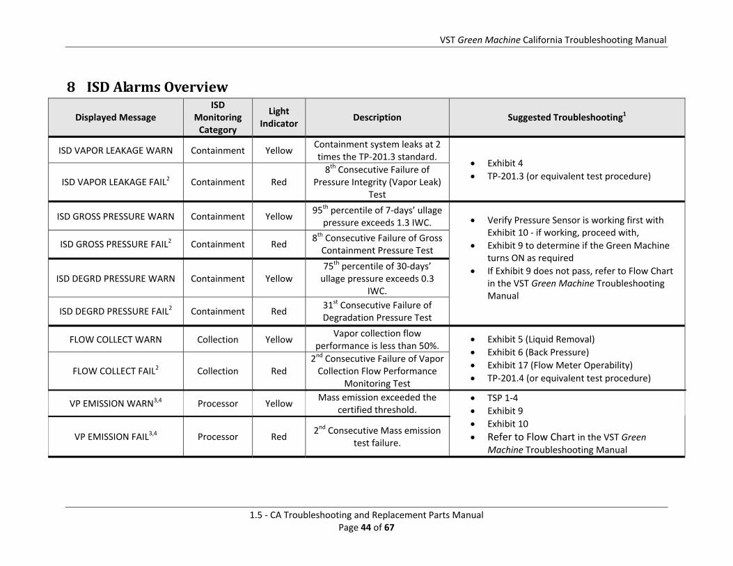
8 ISDAlarmsOverview
Displayed Message ISD
Monitoring Category
Light Indicator
Description Suggested Troubleshooting1
ISD VAPOR LEAKAGE WARN Containment Yellow Containment system leaks at 2 times the TP‐201.3 standard.
Exhibit 4
TP‐201.3 (or equivalent test procedure) ISD VAPOR LEAKAGE FAIL2 Containment Red
8th Consecutive Failure of Pressure Integrity (Vapor Leak)
Test
ISD GROSS PRESSURE WARN Containment Yellow 95th percentile of 7‐days’ ullage
pressure exceeds 1.3 IWC. Verify Pressure Sensor is working first with Exhibit 10 ‐ if working, proceed with,
Exhibit 9 to determine if the Green Machine turns ON as required
If Exhibit 9 does not pass, refer to Flow Chart in the VST Green Machine Troubleshooting Manual
ISD GROSS PRESSURE FAIL2 Containment Red 8th Consecutive Failure of Gross Containment Pressure Test
ISD DEGRD PRESSURE WARN Containment Yellow 75th percentile of 30‐days’ ullage pressure exceeds 0.3
IWC.
ISD DEGRD PRESSURE FAIL2 Containment Red 31st Consecutive Failure of Degradation Pressure Test
FLOW COLLECT WARN Collection Yellow Vapor collection flow
performance is less than 50%. Exhibit 5 (Liquid Removal)
Exhibit 6 (Back Pressure)
Exhibit 17 (Flow Meter Operability)
TP‐201.4 (or equivalent test procedure) FLOW COLLECT FAIL2 Collection Red
2nd Consecutive Failure of Vapor Collection Flow Performance
Monitoring Test
VP EMISSION WARN3,4 Processor Yellow Mass emission exceeded the
certified threshold. TSP 1‐4
Exhibit 9
Exhibit 10
Refer to Flow Chart in the VST Green Machine Troubleshooting Manual
VP EMISSION FAIL3,4 Processor Red 2nd Consecutive Mass emission
test failure.

VST Green Machine California Troubleshooting Manual
1.5 ‐ CA Troubleshooting and Replacement Parts Manual Page 45 of 67
Displayed Message ISD
Monitoring Category
Light Indicator
Description Suggested Troubleshooting1
ISD SENSOR OUT WARN Self‐Test Yellow Failure of Sensor Self‐Test • Confirm ISD sensor & module installation / communication per VR 204 IOM Section 12, Chapter 2 ISD SENSOR OUT FAIL Self‐Test Red
8th Consecutive Failure of Sensor Self‐Test
ISD SETUP WARN Self‐Test Yellow Failure of Setup Test • Confirm EVR/ISD programming per VR 204 IOM
Section 12 ISD SETUP FAIL2 Self‐Test Red
8th Consecutive Failure of Setup Test
Note: The alarms listed in above table will also activate an audible alarm
1See ISD Troubleshooting Manual P/N 577013‐819 found at http://www.veeder.com/object/577013‐819.html and the VST ISD Troubleshooting Manual found at http://www.vsthose.com/pdf/Troubleshooting_Manual_Green Machine.pdf 2ISD Shut Down Alarms – see Figure 48 of IOM Section 12 3This warning will result in an ISD VP Status Warn 4This failure will result in an ISD VP Status Fail
VST Green Machine California Troubleshooting Manual
1.5 ‐ CA Troubleshooting and Replacement Parts Manual Page 46 of 67
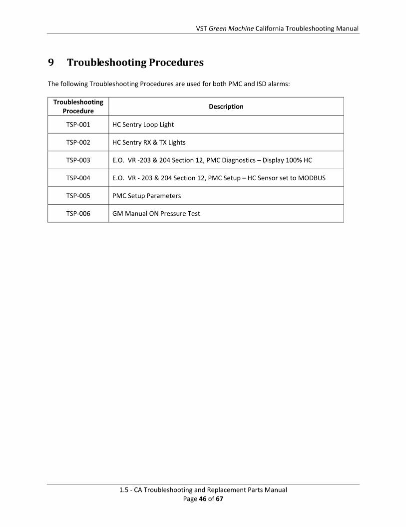
9 TroubleshootingProcedures The following Troubleshooting Procedures are used for both PMC and ISD alarms:
Troubleshooting Procedure
Description
TSP‐001 HC Sentry Loop Light
TSP‐002 HC Sentry RX & TX Lights
TSP‐003 E.O. VR ‐203 & 204 Section 12, PMC Diagnostics – Display 100% HC
TSP‐004 E.O. VR ‐ 203 & 204 Section 12, PMC Setup – HC Sensor set to MODBUS
TSP‐005 PMC Setup Parameters
TSP‐006 GM Manual ON Pressure Test

VST Green Machine California Troubleshooting Manual
1.5 ‐ CA Troubleshooting and Replacement Parts Manual Page 47 of 67
9.1 TSP‐001:HCSentryLoopLight
TSP‐001: HC Sentry Loop Light
Purpose: The LOOP light led provides a simple visual indication of loop current on the 4‐20 mA loop circuit between the VST controller and the HC Sentry and can be used as a means of field debugging a broken loop.
Note:
The HC Sentry acts as an interface between the TLS‐350 and the Green Machine Controller. Conditions for the LOOP light to be ON:
1. The HC Sentry power switch must be ON. 2. The HC Sentry must have 24 VDC power supplied from the VST control panel. 3. A 4‐20 mA signal must supplied from the VST control panel to the HC Sentry.
Steps: Check to make sure the LOOP light is ON
1.
If the LOOP light is not ON: See Figure 32
a. Make sure the HC Sentry power switch is turned ON b. IF the power switch is ON, go to Step 2 c. IF the power switch is OFF, switch on the power ON. d. CLEAR TEST AFTER REPAIR (only if there is an alarm)
2.
Check to see if the HC Sentry has 24 VDC power: See Figure 33
a. Using a multimeter with 24 VDC selected: b. Place the positive probe on the 24 connections c. Place the negative probe on the – connection d. The voltage should read 24 +/‐ 2 VDC e. IF there is 24 VDC at the HC Sentry, GO TO STEP 3
f. If the HC Sentry does not have 24 VDC power:
a. Check the field wires connecting the VST control panel to the HC Sentry: See Figure 34
b. Make sure the VST control panel has 110 VDC power and the disconnect switch on the panel is turned ON
c. Check that the 24 VDC power supply inside the VST control panel has power (a green LED will be ON)
g. IF STEPS 1‐3 are okay and the HC Sentry still does not have 24 VDC power, GO TO STEP 4
VST Green Machine California Troubleshooting Manual
1.5 ‐ CA Troubleshooting and Replacement Parts Manual Page 48 of 67
3.
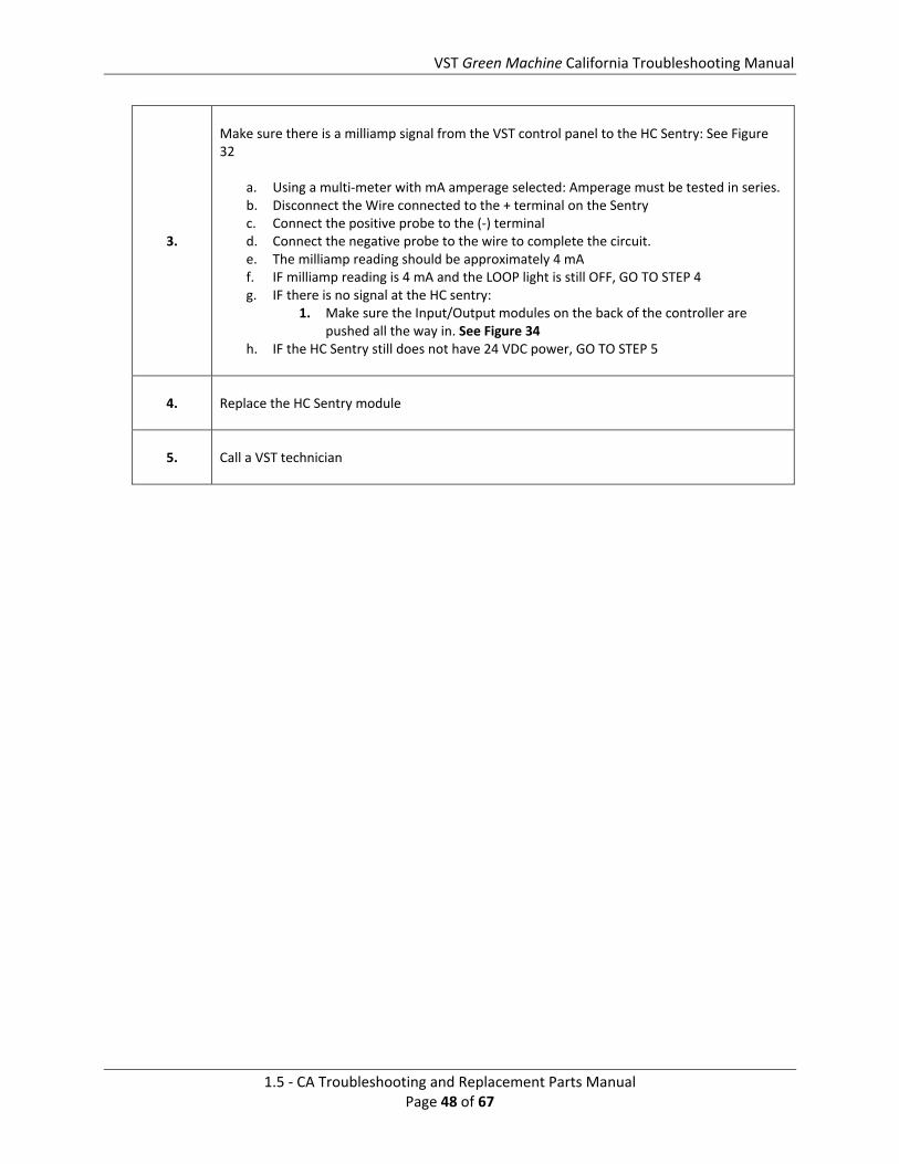
Make sure there is a milliamp signal from the VST control panel to the HC Sentry: See Figure 32
a. Using a multi‐meter with mA amperage selected: Amperage must be tested in series. b. Disconnect the Wire connected to the + terminal on the Sentry c. Connect the positive probe to the (‐) terminal d. Connect the negative probe to the wire to complete the circuit. e. The milliamp reading should be approximately 4 mA f. IF milliamp reading is 4 mA and the LOOP light is still OFF, GO TO STEP 4 g. IF there is no signal at the HC sentry:
1. Make sure the Input/Output modules on the back of the controller are pushed all the way in. See Figure 34
h. IF the HC Sentry still does not have 24 VDC power, GO TO STEP 5
4. Replace the HC Sentry module
5. Call a VST technician

VST Green Machine California Troubleshooting Manual
1.5 ‐ CA Troubleshooting and Replacement Parts Manual Page 49 of 67
9.2 TSP‐002:HCSentryRXandTXLights
TSP‐002: HC Sentry RX and TX Light
Purpose:
RX and TX flashes to indicate data transfer to and from the TLS‐350. The RX LED flashes to indicates that the TLS queried the HC Sentry for Hydrocarbon data via the RS485 HC Sentry Interface Cable. The TX LED flashes to indicate that the HC Sentry is sending the Hydrocarbon data to the TLS.
Note:
The HC Sentry acts as an interface between the TLS‐350 and the Green Machine Controller 1. The HC Sentry must be properly connected to the TLS Comm Board using the HC Sentry
Interface cable 2. The Vapor Processor must be selected in the PMC Setup (203) or the EVR/ISD Setup
(204) 3. The Hydrocarbon Select must be selected in the PMC Setup (203) or the EVR/ISD Setup
(204) and set to Modbus
1.
IF the RX and TX LED lights are not flashing: See Figure 38
a. Make sure the HC Sentry Interface Cable is properly connected to the HC Sentry module and the TLS‐350 Comm Board: See Figure 39
b. Check for continuity and correct pin‐out and re‐crimp/replace RJ‐45 connector. c. IF the cable is properly connected to the HC Sentry and the Comm Board, GO TO STEP
2 d. IF the cable is not properly connected, make the proper connections e. Check to see if the RX and TX lights are flashing f. IF the lights are now flashing g. Check that the HC SENSOR in the PMC Diagnostic (or in the IV8100 report) is reading
either 0% or 20% HC h. CLEAR TEST AFTER REPAIR (only if in alarm)
2.
Check to make sure the TLS‐350 is setup for the Green Machine in PMC Setup (203) or the EVR/ISD Setup (204) a. IF the Green Machine is selected, GO TO STEP 3 b. IF the Green Machine is not selected, make the selection c. Check to see if the RX and TX lights are flashing d. IF the lights are now flashing e. Check that the HC SENSOR in the PMC Diagnostic (or in the IV8100 report) is reading
either 0% or 20% HC f. CLEAR TEST AFTER REPAIR

VST Green Machine California Troubleshooting Manual
1.5 ‐ CA Troubleshooting and Replacement Parts Manual Page 50 of 67
TSP‐002: HC Sentry RX and TX Light
3.
Make sure the HYDROCARBON SELECT is set to MODBUS in the PMC Setup (203) or the EVR/ISD Setup (204)
a. IF the MODBUS is selected, GO TO STEP 4 b. IF the MODBUS is not selected, change to MODBUS c. Check to see if the RX and TX lights are flashing d. IF the lights are now flashing e. Check that the HC SENSOR in the PMC Diagnostic (or in the IV8100 report) is reading
either 0% or 20% HC f. CLEAR TEST AFTER REPAIR
4. Confirm MODBUS card is listed in communication settings. Confirm communication settings are programmed for 9600 bps, 8 data bits, 1 stop bit and NO parity. If settings are correct proceed to step 5.
5. Call a VST technician

VST Green Machine California Troubleshooting Manual
1.5 ‐ CA Troubleshooting and Replacement Parts Manual Page 51 of 67
9.3 TSP‐003:PMCDiagnosis‐Display100%
TSP‐003: PMC Diagnosis‐Display 100%
100% HC is being displayed in the TLS PMC Diagnostic Menu or in the IV8100 ISD Report.
Purpose:
A 100% HC reading in the PMC Diagnostic Menu or in the IV8100 ISD report indicates the TLS PMC Setup (203) or the EVR/ISD Setup (204) is not correct, the TLS is not setup for HYDROCARBON SELECT MODBUS protocol in the PMC Setup (203) or the EVR/ISD Setup, or the signal to the TLS is less than 4.0 mA.
Note:
In TSP‐001, we verified:
1. The LOOP light is ON, which means the 4‐20 mA LOOP circuit is complete between the VST controller and the HC Sentry module.
In TSP‐002, we verified:
1. The RX and TX lights are flashing to indicate data transfer to and from the TLS‐350. 2. TheTLS PMC Setup (203) or the EVR/ISD Setup (204) is set for the Green Machine. 3. The TLS is setup for HYDROCARBON SELECT MODBUS protocol in the PMC Setup (203)
or the EVR/ISD Setup (204).
1.
Check to see if the mA input to the HC Sentry is less than 4.0 mA. This would indicate a fault condition with the VST controller or I/0 module #2 Check the milliamp signal input to the HC Sentry: See Figure 32
a. Using a multi‐meter with mA amperage selected: Amperage must be tested in series. b. Disconnect the Wire connected to the + terminal on the Sentry c. Connect the positive probe to the (‐) terminal d. Connect the negative probe to the wire to complete the circuit. e. The milliamp reading should be approximately 4.0 mA f. IF milliamp reading is between is less than 4.0 mA, GO TO STEP 2
g. IF the milliamp reading is 4.0 mA, GO TO STEP 3
2.
The only reason the mA signal output from the VST controller to be less than 4.0 mA is:
a. The VST controller has malfunctioned and is sending the wrong milliamp value b. The I/O Module #2 has malfunctioned
c. Call a VST technician
3. If the mA reading is 4.0 in Step 1., there must be a problem within the TLS. Call a Veeder‐Root technician

VST Green Machine California Troubleshooting Manual
1.5 ‐ CA Troubleshooting and Replacement Parts Manual Page 52 of 67
9.4 TSP‐004:PMCDiagnostics‐PMCSet‐Up‐HCSensortoMODBUS
TSP‐004: PMC Diagnosis‐HC Sensor to MODBUS
Is The HYDROCARBON SELECT set to MODBUS in the PMC Setup (203) or the EVR/ISD Setup (204)
Purpose: The HYDROCARBON SELECT must be set to MODBUS for the TLS to receive the hydrocarbon MODBUS signal from the HC Sentry module.
Note: Some Multi‐Port cards look almost identical to the MODBUS card. Confirm the correct card is installed by checking the Communication settings on the TLS and confirm the card is listed as MODBUS, NOT RS‐485 or S‐SAT
1.
Make sure the HYDROCARBON SELECT is set to MODBUS in the PMC Setup (203) or the EVR/ISD Setup (204)
a. See Figure 30 for PMC b. See Figure 31 for EVR/ISD c. IF the MODBUS is not selected, change to MODBUS d. Check that the HC SENSOR in the PMC Diagnostic (or in the IV8100 report) is
reading either 0% or 20% HC e. CLEAR TEST AFTER REPAIR (only if in alarm)

VST Green Machine California Troubleshooting Manual
1.5 ‐ CA Troubleshooting and Replacement Parts Manual Page 53 of 67
Figure 30: PMC Set‐up

VST Green Machine California Troubleshooting Manual
1.5 ‐ CA Troubleshooting and Replacement Parts Manual Page 54 of 67
Figure 31: ISD Set‐up

VST Green Machine California Troubleshooting Manual
1.5 ‐ CA Troubleshooting and Replacement Parts Manual Page 55 of 67
9.5 TSP‐005:PMCSetupParameters
TSP‐005: PMC Setup Parameters
Purpose: Checking the PMC parameters will check that the TLS is setup for the Green Machine.
Note: Are the PMC Setup (VR‐203) parameters set correctly for the Green Machine
1.
Make sure the PMC Setup (VR‐203) parameters are set to the Green Machine
1. Are the PMC Setup parameters set correctly for the Green Machine a. VAPOR PROCESSOR: VST Green Machine b. TURN OFF VAPOR PROCESSOR INCHES: ‐2.00 c. TURN ON VAPOR PROCESSOR INCHES: +0.20 d. HYDROCARBON SELECT: ENTER (Selects MODBUS) e. SET ANALYSIS TIME: ENTER f. SET TEST START TIME: 11:59 PM (USER DEFINED) g. SET POST DELAY DURATION: 001 (DEFAULT) h. PRESSURE SENSOR SELECT: ENTER i. LABEL: (PS label) SN# (10 char) ENABLE
2. IF the PMC Setup parameters are not setup correctly, make the correction
CLEAR TEST AFTER REPAIR
2.
Make sure the PMC Setup (VR‐204) parameters are set to the Green Machine
3. Are the PMC Setup parameters for the VST Green Machine (VR‐204) set correctly for the Green Machine
a. TURN ON VAPOR PROCESSOR INCHES: +0.20 a. IF the PMC Setup parameters are not setup correctly, make the correction b. CLEAR TEST AFTER REPAIR

VST Green Machine California Troubleshooting Manual
1.5 ‐ CA Troubleshooting and Replacement Parts Manual Page 56 of 67
9.6 TSP‐006:GMManualRUNCheck
TSP‐006: GM Manual RUN Check
Conducting a GM Manual RUN Test using the TLS Manual ON mode
Purpose:
Putting the Green Machine in the Manual ON Mode will close a relay at the TLS instructing the Green Machine to RUN regardless of UST pressure. By running the Green Machine in the Manual ON mode, the UST pressure will decrease when the Green Machine is in the RUN mode.
Note:
This procedure will check the:
1. Field wiring connections between the TLS Relay Output and the VST control panel 2. Field wiring between the VST control panel and the Green Machine 3. The VST control panel will also be check for loose wires or for any malfunctioned
electrical components.
1.
Put the Green Machine in the Manual ON mode at the TLS
a. In the PMC Diagnostic Menu, check to see that the UST pressure is decreasing b. IF the UST pressure is not decreasing, GO TO STEP 2
2.
Check the VST controller
a. Check to see if the VST controller display is showing Green Machine ON b. IF the controller is not showing Green Machine ON, GO TO STEP 3
(There are two reasons the controller is not showing Green Machine ON:
a. The VST controller is not receiving a signal from the TLS to turn ON b. There is a malfunction with the VST controller
3.
Check connections from the VST control panel to the TLS Output Relay board
a. There is one wire labeled TLS‐350 (110 VAC HOT) that connects the VST control panel to the TLS RUN Output Relay. The TLS RUN Output Relay is powered from the ESO 110 V HOT circuit. (See Figure 35)
1. Check to see that both Output Relay wires are properly connected 2. IF both wires are properly connected, GO TO STEP 4.
b. IF the wires are not properly connected
1. Put the Green Machine in the Manual OFF mode at the TLS 2. Make the wiring corrections 3. Put the Green Machine in the Manual ON mode 4. Check to see if the UST pressure is decreasing 5. IF the UST pressure is decreasing 6. CLEAR TEST AFTER REPAIR
c. IF the UST pressure is not decreasing, GO TO STEP 4

VST Green Machine California Troubleshooting Manual
1.5 ‐ CA Troubleshooting and Replacement Parts Manual Page 57 of 67
4.
Check if the Vapor Processor is selected in the RELAY TYPE in the Output Relay Setupa. Follow the instructions in the Veeder Root PMC or ISD Install, Setup, & Operation
Manual to check the RELAY CONFIG, RELAY DESIGNATION, RELAY TYPE, and ORIENTATION.
b. IF the RELAY is setup correctly, GO TO STEP 5 c. IF the RELAY is not setup correctly, make the correction d. CLEAR TEST AFTER REPAIR
5. Call a VST Technician
Figure 32: HC Sentry Front View
Figure 33: 24 VDC Power and 4‐20 mA Signal Connections on the HC Sentry Module

VST Green Machine California Troubleshooting Manual
1.5 ‐ CA Troubleshooting and Replacement Parts Manual Page 58 of 67
Figure 34: Controller Input / Output Modules Connections

VST Green Machine California Troubleshooting Manual
1.5 ‐ CA Troubleshooting and Replacement Parts Manual Page 59 of 67
Figure 35: HC Sentry Field Wiring to the VST Control Panel

VST Green Machine California Troubleshooting Manual
1.5 ‐ CA Troubleshooting and Replacement Parts Manual Page 60 of 67
Figure 36: TLS‐350 Inspector Port Communications Installation

VST Green Machine California Troubleshooting Manual
1.5 ‐ CA Troubleshooting and Replacement Parts Manual Page 61 of 67
Figure 37: TLS‐350 Inspector Port Communications Installation Option B

VST Green Machine California Troubleshooting Manual
1.5 ‐ CA Troubleshooting and Replacement Parts Manual Page 62 of 67
Figure 38: HC Sentry Back View

VST Green Machine California Troubleshooting Manual
1.5 ‐ CA Troubleshooting and Replacement Parts Manual Page 63 of 67
Figure 39: HC Sentry to the TLS Comm Board Cable Connections

VST Green Machine California Troubleshooting Manual
1.5 ‐ CA Troubleshooting and Replacement Parts Manual Page 64 of 67
10 VaporFiltrationCartridge If the Green Machine does not pass the Annual Compliance Bag Test, and all other Troubleshooting has shown no failure mode, the Vapor Filtration Cartridge may need to be replaced.

VST Green Machine California Troubleshooting Manual
1.5 ‐ CA Troubleshooting and Replacement Parts Manual Page 65 of 67
11 VaporFiltrationCartridgeReplacementSafety
Use lockout / tagout procedures prior to starting work.
Figure 40: Vapor Filtration Cartridge Replacement

VST Green Machine California Troubleshooting Manual
1.5 ‐ CA Troubleshooting and Replacement Parts Manual Page 66 of 67
11.1 RemovingtheVaporFiltrationCartridge
Figure 40
7. Disconnect power to the VST Control Panel. (The power, ground, and neutral
will be completely disconnected from the Green Machine.)
8. Follow lockout/tagout procedures
9. Unlock the hasps and remove the cover from the Green Machine
10. Disconnect and completely remove the two ½” 45° flare tubing from the
cartridge base and the top plate of the Vapor Filtration Cartridge housing
11.
Remove the tubing fittings from the top plate and the Cartridge base and
keep for re‐use when installing the new Cartridge assembly
NOTE: Use caution to avoid damaging the flared ends on the tubing or the
threads on the nuts after removal
12. Unscrew the 4 bolts that secure the base of the Cartridge to the base of the :
keep for re‐use
13. Remove the Vapor Filtration Cartridge Assembly from the base of the
Green Machine
14. Install plugs in the top plate and Cartridge base, use Teflon tape to seal the
threads
15. Package the used Vapor Filtration Cartridge Assembly in a plastic bag for
disposal
CAUTION: FOLLOW RECOMMENDED EPA REQUIREMENTS FOR THE PROPER DISPOSAL OF
THE CARTRIDGE

VST Green Machine California Troubleshooting Manual
1.5 ‐ CA Troubleshooting and Replacement Parts Manual Page 67 of 67
11.2 ReplacingaNewVaporFiltrationCartridgeFigure 40
16. Place the NEW Vapor Filtration Cartridge Assembly on the Green Machine base
17. Install and tighten the 4 bolts that secure the Cartridge assembly to the base
of the Green Machine
18. Remove the two plugs from the Vapor Filtration Cartridge Assembly
19.
Re‐Install the fittings on the top plate and Cartridge base. The zinc plated fitting
must be installed on the top plate
On the top plate, use the Zinc plated ½” NPT x ½” 45 deg. flare 90 deg. elbow as shown in Figure 40, item # 6
On the Cartridge base, use the brass ½” NPT x ½” 45 deg. flare 90 deg. elbow and the adapter as shown in Figure 40, item # 7
20. Re‐install the ½” 45° flare tubing on the base and the top plate of the Vapor
Filtration Cartridge
NOTE: When tightening the 45° flare nuts, clamp the tube flare between the nut and the
nose body of the tube by screwing the nut on finger‐tight. Tighten with a wrench an
additional ¼‐turn for a metal‐to‐metal seal
21. Put the cover on the Green Machine and lock the hasps
22. Remove the lock(s) and tags from the lockout/tagout
23. After the work is completed, turn ON power to the VST Control Panel. The
Green Machine is now operational