troubleshooting guide b2000 cyclone bender · troubleshooting guide b2000 cyclone® bender service...
TRANSCRIPT

1
GAR_TL_045_0515
Troubleshooting Guide
B2000 Cyclone® Bender
SERVICE INSTRUCTIONS
These Service instructions are intended for use by a qualified personal at Authorized Gardner Bender Service Centers. Users of Gardner Bender equipment should see the bender instruction sheet for installation, operation and maintenance information.
SAFETY ISSUES
1.0 Troubleshooting Guide ............................................ 22.0 Pendant Troubleshooting ........................................ 43.0 Disassemble Instructions ....................................... 5 Limit Switch ........................................................ 5 Roller Housing .................................................... 5 Bender Shoe ....................................................... 5 Circuit Board ....................................................... 5 Electric Motor ..................................................... 5 Drive Sprocket Assembly ................................... 64.0 Reassembly Instructions ........................................ 6 Drive Belt and Sprockets ................................... 6 Motor Assembly ................................................. 7 Shoe Shaft .......................................................... 7 Roller Housing .................................................... 7 Prinited Circuit Board ......................................... 7 Limit Switch Assem/Wiring 7
5.0 Zero Adjustment ...................................................... 86.0 Parts Breakdown ..................................................... 9 B2000 Bender ..................................................... 9 Bottom of Electric Motor ................................. 10 Shoe .................................................................. 11 Limit Switch ...................................................... 12 Roller Housing .................................................. 13 Upper Roller / Handle ...................................... 14 Sprocket Housing ............................................. 15 Handle / Control Circuit ................................... 167.0 Wiring Schematic .................................................. 178.0 B2000 Wiring Diagram .......................................... 189.0 Maintenance .......................................................... 19
REQUIRE TOOLS AND TEST EQUIPMENT
• Torque Wrench
• Allen Wrench
• Open Wrench ½ “ and 9/16 “
• Sockets
• White Assembly Grease
• Soft Head Mallet
• 2” EMT and Rigid Conduit
• Silicone
• Multi-meter
• Strap Wrench
• Repair Parts Sheet
• Instructions Manual
TABLE OF CONTENTS
WARNING: Do not locate the bender on damp or wet surfaces. Do not stand on damp or wet surfaces when repairing or operating the bender.
WARNING: To avoid electrical shock, always unplug the bender power cord before removing end plates, motor or any electrical wiring.
CAUTION: To avoid physical injury, use two people to remove and install the bending shoe or to move it from place to place.
CAUTION: Keep hands, clothing and electrical power cords away from moving rollers, bending shoe and exposed gears.
IMPORTANT: Prior to installation: apply a coat of molycoat or equivalent to all shafts. When installing shafts, use soft head mallets to seat in position.

2
PROBLEM POSSIBLE CAUSE ACTION
Bending shoe does not move when switch is in bend or return position.
No power to bender Check power cord. Use 110 VAC, 15 amp outlet.
12V DC power supply failed Unplug bender power cord. On P.C. board, remove cover on plug. Connect positive meter lead on black wire and negative lead on green wire. Plug in the power cord. Meter should indicate 12V DC. If not, replace P.C. board.
Power circuit on P.C. board is mal-functioning
Control circuit is not activating bender. Replace P.C. board, refer to Repair Parts Lists.
Motor overload or/overheated Allow time for motor to cool. Activate bender. If motor will not run, perform continuity check.Replace damaged motor.
Bend switch does not function, return switch functions.
Remote pendant bend switch or wiring inoperative
Unplug bender power cord, test for continuity at hard-ness to pendant. Attach leads to black and white wires. Press bend switch. If no continuity, check switch under pendant cover. Place ohm meter on leads for black wire and white wire. Depress bend switch. If no continuity, replace switch, Part Number - DA9687372.If continuity exists, wire harness is faulty.
Bend limit switch or harness tolimit switch is malfunctioning
Unplug bender power cord. Perform continuity check on green and orange wires. Press bend limit switch actu-ator tab, if no continuity, replace switch, Part Number - DA9687372. If continuity exists, check wiring harness. (Refer to Repair Parts List for illustration and additional part numbers).
Printed circuit board malfunctioning Replace P.C. board, Part Number- EC2006 or HC12.
Bend function works, return switch does not.
Remote pendant switch or wiring is malfunctioning.
Unplug bender power cord. Perform continuity check on pendant return switch. Attach leads to black wire and white wire, depress return switch. If no continuity, replace switch, Part Number - DA9687372. If continui-ty exists, check wire harness. Attach ohm meter leads to orange and blue wires. Depress return switch if no continuity; replace wire harness, Part Number – CL-712647SR.
Bender shoe will not return when pressing return and jog but-ton. (Old Pendant)
Jog button malfunctioning or wire harness to pendant damaged.
Unplug bender power cord. Perform continuity check on wire harness. Attach leads to red and green wires. Depress override (jog) button. If no continuity, check jog switch in pendant control, (Parts Not Available). Remove cover, place leads on red and green wires at switch. Depress jog switch. If no continuity, replace switch, (Parts Not Available). If continuity exists, fault lies in wire harness. (Refer to Repair Parts List for illustration and additional part numbers).
Bender shoe returns to zero, indicator light does not light.
Zero limit switch or harness to switch is malfunctioning.
Unplug bender power cord. Perform continuity check on harness from pendant control. Attach leads to black and red wires. If no continuity, check the zero limit switch (see illustration in Repair Parts List). Attach the leads to black and red wires at the limit switch. Depress limit switch actuator tab. If no continuity, replace switch, Part Number- DA9687372. If continuity exists, replace wire harness.
Bender consistently develops over bends.All mechanical adjustments are accomplished
Braking resistor on P.C. board is not malfunctioning.
Unplug bender power cord. Perform resistance mea-surement on breaking resistor. Remove chassis from rear of bender. Attach ohm meter across to brown and gray wires. If meter reads 9-11 ohms + 1 ohm, resistor is good. If meter reads above 11 ohms, replace resistor.
P.C. board circuit is not functioning. Remove and replace P.C. Board, Part Number DA7034380.
1.0 TROUBLESHOTTING GUIDE

3
PROBLEM POSSIBLE CAUSE ACTION
Bender does not stop at selected bend size (angle).
Bend limit switch is not being actu-ated by shoe post
Remove shoe indicator plate. Observe the tabs as they pass the bend limit switch. Adjust switch until tabs cor-rectly contact the posts.
Bend limit switch is not functioning Unplug the bender power cord. Attach leads to orange and green wires at the switch. Continuity should exist. Push the actuator tab (on the switch). Continuity should be broken. If not, replace the switch.
Breaking resistor is not functioning Unplug the bender power cord. Perform resistance mea-surement on breaking resistor. Attach leads across termi-nals. A 9-11 ohms (+ 1 ohm) resistance is normal. Other readings are unacceptable. Replace breaking resistor, Part Number - DA7034380.
Brake circuit (P.C. board) not func-tioning
If all other tests are positive, replace P.C. board, Part Number - DA7034380.
During return func-tion, bender shoe does not stop at zero point.
Plunger on return limit switch is not being tripped by the trip ring tab
Remove limit switch assembly. Observe tab to return lim-it switch contact. If switch is not contacting tab, adjust switch position.
Bend limit switch is not functioning
If post to switch contact is correct, perform bend limit switch continuity check. Attach leads to orange and green wires. Press limit switch tab. Continuity should result. If not, replace switch.
Return limit switch not functioning
Perform return limit switch continuity check. Attach leads to white and blue wires. Continuity must exist when pressing actuator tab. If not replace return limit switch.
Brake resistors not functioning Unplug power cord. Perform resistance measurement on each resistor. Place ohm meter leads on gray and brown wires. Meter should read 9-11 ohms. If reading is over 11 ohms, replace resistors.
Bend function works, return function results in bending direction.
Direction circuit, on P.C. board not functioning
Replace P.C. board.
Return function works, bend func-tion results in shoe moving in return direction.
Brake circuit on P.C. board not functioning
If all other tests are positive, replace P.C. board.
Return function works. Depressing bend switch, shoe moves in return.
Direction circuit, on P.C. board, not functioning
Replace P.C. board
4
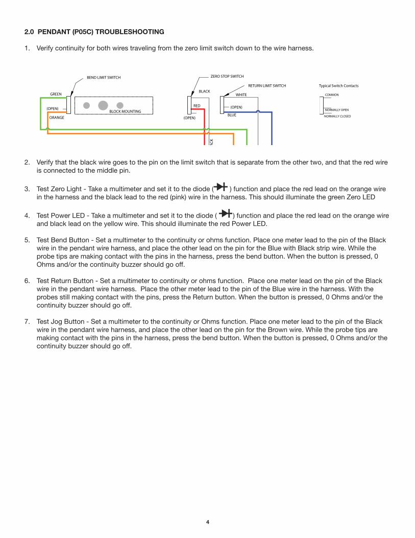
2.0 PENDANT (P05C) TROUBLESHOOTING
1. Verify continuity for both wires traveling from the zero limit switch down to the wire harness.
2. Verify that the black wire goes to the pin on the limit switch that is separate from the other two, and that the red wire is connected to the middle pin.
3. Test Zero Light - Take a multimeter and set it to the diode ( ) function and place the red lead on the orange wire in the harness and the black lead to the red (pink) wire in the harness. This should illuminate the green Zero LED
4. Test Power LED - Take a multimeter and set it to the diode ( ) function and place the red lead on the orange wire and black lead on the yellow wire. This should illuminate the red Power LED.
5. Test Bend Button - Set a multimeter to the continuity or ohms function. Place one meter lead to the pin of the Black wire in the pendant wire harness, and place the other lead on the pin for the Blue with Black strip wire. While the probe tips are making contact with the pins in the harness, press the bend button. When the button is pressed, 0 Ohms and/or the continuity buzzer should go off.
6. Test Return Button - Set a multimeter to continuity or ohms function. Place one meter lead on the pin of the Black wire in the pendant wire harness. Place the other meter lead to the pin of the Blue wire in the harness. With the probes still making contact with the pins, press the Return button. When the button is pressed, 0 Ohms and/or the continuity buzzer should go off.
7. Test Jog Button - Set a multimeter to the continuity or Ohms function. Place one meter lead to the pin of the Black wire in the pendant wire harness, and place the other lead on the pin for the Brown wire. While the probe tips are making contact with the pins in the harness, press the bend button. When the button is pressed, 0 Ohms and/or the continuity buzzer should go off.
WHITE ORANGE GREEN
RED BLACK BLUE
YELLOW GREY
(43) (42) (41)
(46) (45) (44)
(48) (47)
(OPEN)
RED
BLUE
(OPEN)
WHITE
ORANGE
(OPEN)
GREEN
GREY
YELLOW
RED
BLA
CK
FEMALE CONNECTOR
MALE CONNECTOR
BEND LIMIT SWITCH ZERO STOP SWITCH
P8
P7
P5
P6
RED
BLACK
BLACK
RED
POWER CORD
FEMALE CONNECTOR
MALE CONNECTOR
WH
ITE
BLA
CK
BLA
CK
BLACK
BLACK
WHITE
WHITE
WHITE
WHITE
BLACK
CIRCUIT BOARD
BLACK
RETURN LIMIT SWITCH Typical Switch Contacts
BLOCK MOUNTING
CONNECTOR TO CIRUIT BOARD
AZ
BLA
CK
BMK3 SWITCH
NORMALLY CLOSED
NORMALLY OPEN
COMMON
BOTTOM OF MOTOR
NOTE: 2-LONG STUDS FOR COVER MOUNTING ONLY
Wiring Schematic
5
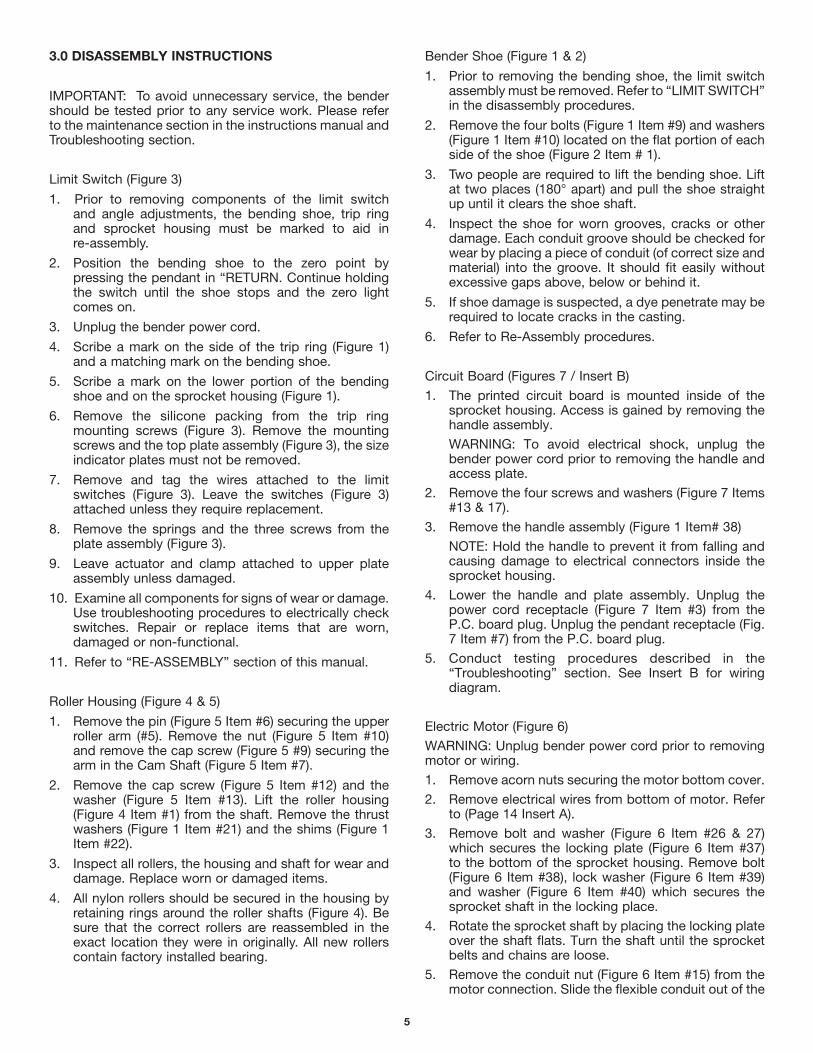
3.0 DISASSEMBLY INSTRUCTIONS
IMPORTANT: To avoid unnecessary service, the bender should be tested prior to any service work. Please refer to the maintenance section in the instructions manual and Troubleshooting section.
Limit Switch (Figure 3)
1. Prior to removing components of the limit switch and angle adjustments, the bending shoe, trip ring and sprocket housing must be marked to aid in re-assembly.
2. Position the bending shoe to the zero point by pressing the pendant in “RETURN. Continue holding the switch until the shoe stops and the zero light comes on.
3. Unplug the bender power cord.
4. Scribe a mark on the side of the trip ring (Figure 1) and a matching mark on the bending shoe.
5. Scribe a mark on the lower portion of the bending shoe and on the sprocket housing (Figure 1).
6. Remove the silicone packing from the trip ring mounting screws (Figure 3). Remove the mounting screws and the top plate assembly (Figure 3), the size indicator plates must not be removed.
7. Remove and tag the wires attached to the limit switches (Figure 3). Leave the switches (Figure 3) attached unless they require replacement.
8. Remove the springs and the three screws from the plate assembly (Figure 3).
9. Leave actuator and clamp attached to upper plate assembly unless damaged.
10. Examine all components for signs of wear or damage. Use troubleshooting procedures to electrically check switches. Repair or replace items that are worn, damaged or non-functional.
11. Refer to “RE-ASSEMBLY” section of this manual.
Roller Housing (Figure 4 & 5)
1. Remove the pin (Figure 5 Item #6) securing the upper roller arm (#5). Remove the nut (Figure 5 Item #10) and remove the cap screw (Figure 5 #9) securing the arm in the Cam Shaft (Figure 5 Item #7).
2. Remove the cap screw (Figure 5 Item #12) and the washer (Figure 5 Item #13). Lift the roller housing (Figure 4 Item #1) from the shaft. Remove the thrust washers (Figure 1 Item #21) and the shims (Figure 1 Item #22).
3. Inspect all rollers, the housing and shaft for wear and damage. Replace worn or damaged items.
4. All nylon rollers should be secured in the housing by retaining rings around the roller shafts (Figure 4). Be sure that the correct rollers are reassembled in the exact location they were in originally. All new rollers contain factory installed bearing.
Bender Shoe (Figure 1 & 2)
1. Prior to removing the bending shoe, the limit switch assembly must be removed. Refer to “LIMIT SWITCH” in the disassembly procedures.
2. Remove the four bolts (Figure 1 Item #9) and washers (Figure 1 Item #10) located on the flat portion of each side of the shoe (Figure 2 Item # 1).
3. Two people are required to lift the bending shoe. Lift at two places (180° apart) and pull the shoe straight up until it clears the shoe shaft.
4. Inspect the shoe for worn grooves, cracks or other damage. Each conduit groove should be checked for wear by placing a piece of conduit (of correct size and material) into the groove. It should fit easily without excessive gaps above, below or behind it.
5. If shoe damage is suspected, a dye penetrate may be required to locate cracks in the casting.
6. Refer to Re-Assembly procedures.
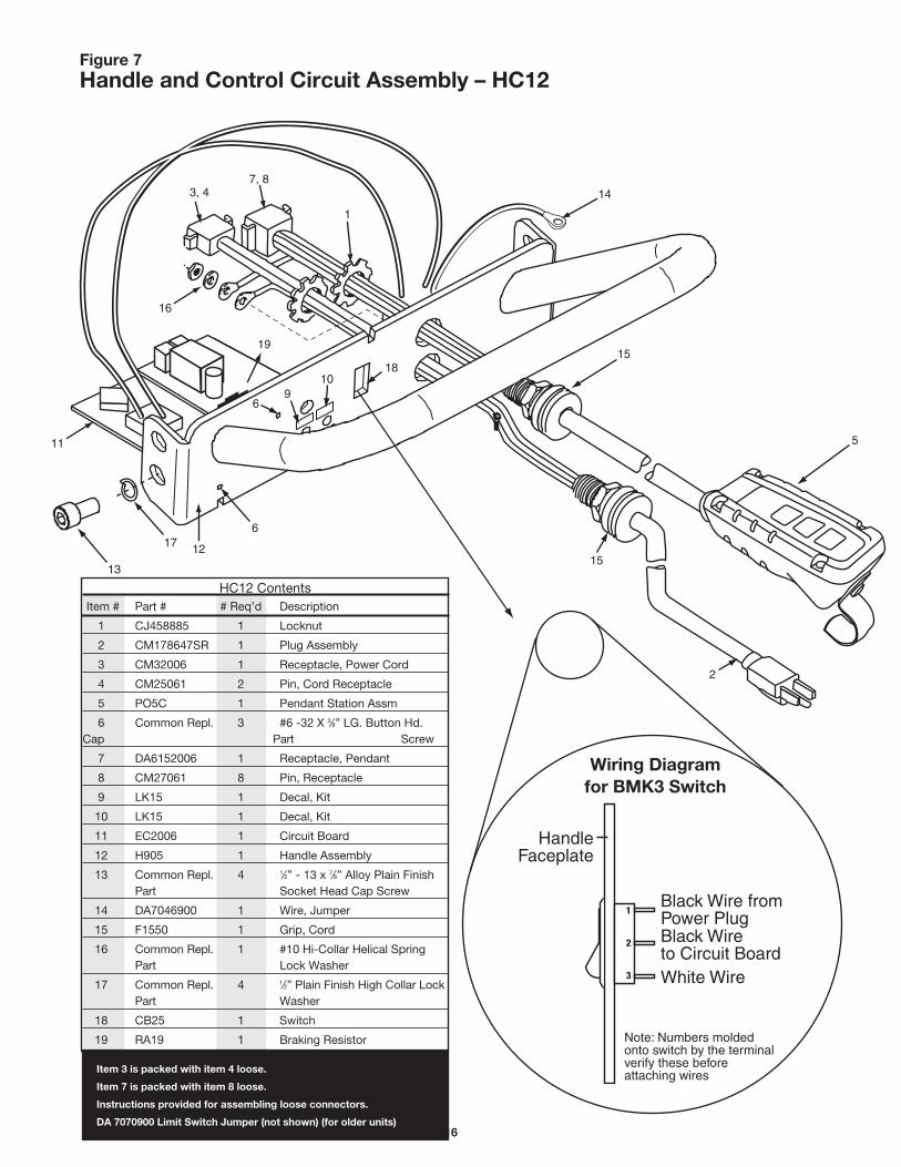
Circuit Board (Figures 7 / Insert B)
1. The printed circuit board is mounted inside of the sprocket housing. Access is gained by removing the handle assembly.
WARNING: To avoid electrical shock, unplug the bender power cord prior to removing the handle and access plate.
2. Remove the four screws and washers (Figure 7 Items #13 & 17).
3. Remove the handle assembly (Figure 1 Item# 38)
NOTE: Hold the handle to prevent it from falling and causing damage to electrical connectors inside the sprocket housing.
4. Lower the handle and plate assembly. Unplug the power cord receptacle (Figure 7 Item #3) from the P.C. board plug. Unplug the pendant receptacle (Fig. 7 Item #7) from the P.C. board plug.
5. Conduct testing procedures described in the “Troubleshooting” section. See Insert B for wiring diagram.
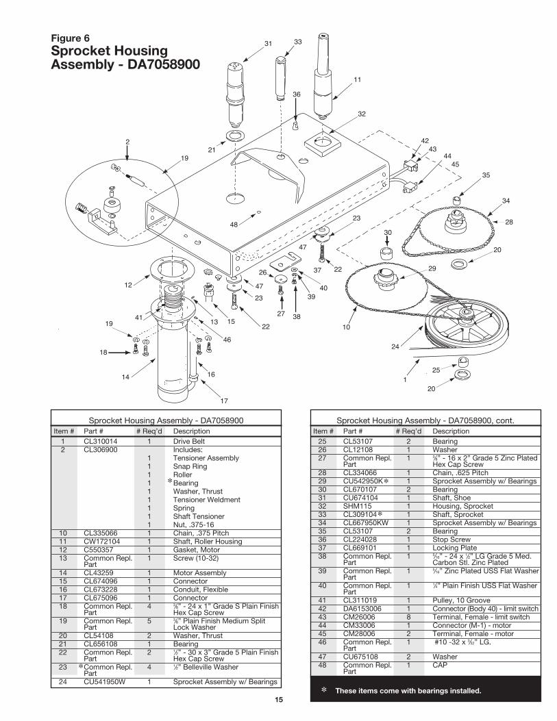
Electric Motor (Figure 6)
WARNING: Unplug bender power cord prior to removing motor or wiring.
1. Remove acorn nuts securing the motor bottom cover.
2. Remove electrical wires from bottom of motor. Refer to (Page 14 Insert A).
3. Remove bolt and washer (Figure 6 Item #26 & 27) which secures the locking plate (Figure 6 Item #37) to the bottom of the sprocket housing. Remove bolt (Figure 6 Item #38), lock washer (Figure 6 Item #39) and washer (Figure 6 Item #40) which secures the sprocket shaft in the locking place.
4. Rotate the sprocket shaft by placing the locking plate over the shaft flats. Turn the shaft until the sprocket belts and chains are loose.
5. Remove the conduit nut (Figure 6 Item #15) from the motor connection. Slide the flexible conduit out of the

6
elbow and pull the wires out.
6. Remove the rear access plate by removing 4 cap screws and washers.
7. Remove the four cap screws and washers (Figure 6 Item #18 & 19) securing the motor to the sprocket housing, Remove the motor, unhook the drive belt from the motor shaft.
8. Remove the belt tensioner (Figure 6 Item #2) by removing nut and washer. The tensioner shaft is spring loaded. Remove the tensioner assembly spring and shaft from inside the sprocket housing.
Drive Sprocket Assembly (Figure 6)
1. Separate the drive chain (Figure 1 Item #8) by removing the master link.
NOTE: The master link is assembled with clip on top – it must be reassembled the same way.
2. Remove drive sprocket (Figure 1 Item #7) from shoe shaft (Figure 6 Item # 31), Remove spacer (Figure 1 Item #5) and DU Washer (Figure 1 Item #6).
3. Remove dust cap (Figure 1 Item #36) from sprocket housing.
4. Remove cap screw (Figure 6 Item #22) and washer (Figure 6 Item #47 / 23). Lightly tap bottom of roller housing shaft (Figure 6 Item #11) to remove it from the sprocket housing.
NOTE: Use brass drift pin or leather mallet to remove shafts.
5. Rotate sprocket (Figure 6 Item # 34) until the master link for chain (Figure 6 Item #28) appears in the access opening.
6. Remove the master link and remove the chain from the sprocket housing.
7. Remove the cap screw (Figure 1 Item #22) and washer (Figure 1 Item #23 / 47). Carefully remove shoe shaft (Figure 6 Item #31) by holding the limit switch wires inside the sprocket housing and lifting the shaft out of the housing. Remove bearing (Figure 6 Item# 21).
8. While removing the sprocket shaft (Figure 6 Item #33), hold the sprocket down, tap the shaft (from the bottom) and remove it from the sprocket housing.
9. Remove sprocket assemblies (#8) and (#9) from the housing and remove thrust washer (#10).
10. Remove sprocket assembly (#11) and thrust washer (#12) from the housing.
11. Clean the sprocket housing (inside), wipe away grease and dirt. Use lower pressure air hose to remove any accumulation of debris.
12. Clean all sprockets, gear teeth and chains. Check for worn gear teeth and worn or damaged bearings. Check chains and drive belt for wear and/or damage. Replace damaged or worn items.
4.0 RE-ASSEMBLY INSTRUCTIONS
Drive Belt And Sprockets (Figure 6)
1. Position drive belt sprocket (Figure 6 Item #24) and shoe sprocket (Figure 6 Item #29) on a flat surface. Connect 3/8” chain (Figure 6 Item #10) to drive belt sprocket (upper gear) and to shoe bracket (large lower gear). Insert master link (pin up).
2. Lift the belt sprocket, slip the belt (Figure 6 Item # 1) under the sprockets and position it in the sprocket grooves. Lift the shoe sprocket, position the belt so it is around sprocket shaft boss (Figure 6).
3. Pull the belt tight around the belt sprocket. Fasten the loose end together with a rubber band to keep the belt snug on the sprocket.
4. Insert drive sprocket (Figure 6 Item #34) into the housing (large gear up) and position the gear through the hole (under bracket). Place small blocks between the gear and the housing to hold the sprocket against the inside of the housing.
5. Position shoe sprocket (Figure 6 Item #29) and belt sprocket into the housing, from the motor end. The belt sprocket is aligned under the drive sprocket and the shoe sprocket is positioned under the shoe shaft hole. The loose belt end belongs toward the motor end of the housing. Position thrust washer (Figure 6 Item #20) between the belt sprocket and drive sprocket, bearing surface facing up.
6. Place the thrust washer (Figure 6 Item #20) under the shoe sprocket.
7. Align drive sprocket (Figure 6 Item #34) and belt sprocket (Figure 6 Item #24) with the center hold (under bracket on housing). Place bearing (Figure 6 Item #35) on top of sprocket. Remove blocks.
8. Mark high point on end of sprocket shaft (Figure 6 Item #33). Lubricate shaft with light coat of general purpose grease. Insert shaft (flats first) through the sprockets. Drive flush with the top sprocket.
9. Insert cap screw (Figure 6 Item #27) through washer (Figure 6 #26) and locking plate (Figure 6 Item #37). Torque to 28 – 32 ft. lb. Install cap screw into sprocket shaft under housing. Install cap screw (Figure 6 Item #38) and washer (Figure 6 Item #39 /40) in hole aligned with lock plate slot. Torque to 19 – 21 ft. lb.
10. Mark the middle link of chain (Figure 6 Item #28). Put the chain over the small (upper) gear teeth of sprocket (Figure 6 Item #29). Place chain around large gear of sprocket (Figure 6 Item #34).
11. Install master link through the access hole in the housing (pins up).
12. Install tensioner assembly by inserting shaft (Figure 6 Item #1) through the inside of the sprocket housing (threads outward). Assemble the lock washer (Figure 6 Item #2) and nut and tighten.
13. From inside the sprocket housing slide the spring over the shaft, then slide the tension roller over the shaft (roller toward drive belt). Place something under the tension bracket to wedge it in place away from the drive belt.

7
Motor Assembly (Figure 6 / Insert A)
1. Remove restraint from drive belt.
2. Place gasket (#1) on motor flange. Insert motor into the sprocket housing. Install one mounting screws and washers into mounting hole closer to the belt
3. Position the drive belt over the motor pulley. Align the belt to ride at the same height on the motor pulley and grooved sprocket.
4. Using a strap tool put it around the motor to help align the mounting holes with the motor. Install the 3 mounting screws and washers.
5. Remove the wedge from beneath the tension bracket. The roller should engage the belt.
6. Connect wiring to base of motor. (Figure 1 Insert B).
Shoe Shaft (Figure 6)
1. Position the shoe shaft (Figure 6 Item #31) in the sprocket housing (Figure 6 Item #32) with the hole for the wiring facing the hole in the housing.
2. Insert the D.U. bearing (Figure 6 Item #21) between the shoe sprocket and the sprocket housing (Figure 6 Item #32).
3. Push the shoe sprocket (Figure 1 Item #7) into the sprocket until it rests on the housing. Install two washers (Figure 6 Item #23 / 47) and cap screw (#22) through bottom of housing and tighten to secure shoe shaft. Torque 68-82 ft. lbs.
4. Install connector into bottom of sprocket housing and tighten. Install bushing in wire hole (housing) near the shoe shaft.
5. Install limit switch wires (Figure 1 Item #3) from inside sprocket housing, through the bushing and into the side of the shoe shaft. Push the wires up and through the top of the shaft. Pull at least six inches out of the shaft.
6. Position shoe drive sprocket (Figure 1 Item #7) over the shoe shaft. Install the drive chain around the shoe sprocket and the drive sprocket (Figure 1 Item #8) (under housing bracket).
7. Install master link, pins down. Support the sprocket with blocks to level the chain and fasten the master link.
8. Place the thrust washer (Figure 1 Item #6) and washer (#5) on the shoe shaft. Place the bending shoe over the shaft and align the mounting holes with the sprocket holes. Use alignment marks placed during removal, to position the shoe on the shaft. Install four cap screws (Figure 1 Item #9) and washers (#10) to secure the shoe and sprocket. Torque to 68-92 ft. lbs.
Roller Housing (Figure 4 & 5)
1. Insert roller housing shaft (Figure 6 Item #11) into sprocket housing until it seats in bottom of the housing.
2. Secure the shaft with washer (Figure 6 Item #23) and cap screw (Figure 6 Item #22) from the bottom of the sprocket housing.
3. Place shim (Figure 1 Item #22) and washer (#21) over the shaft. Install the complete roller housing on the shaft. Secure with cap screw (Figure 5 Item #12) and washer (#13).
4. Position the upper roller arm (Figure 4 Item #11) in the bracket and install mounting bolt (Figure 5 Item #9), washer (#10), nut washer (#11) and pin (#6).
Printed Circuit Board (Figures 7 / Insert B)
1. Connect the sprocket harness receptacle to the board plug. Connect motor wire receptacle to the board plug.
2. Connect the pendant receptacle to the P.C. board plug. Connect power cord receptacle to P.C. board plug. Be sure the harness ground wires are attached to the end plate.
3. Position the handle assembly against the sprocket housing and attach with 4 washers and screws.
Limit Switch Assembly & Wiring (Figure 3 / Insert B)
1. Insert the four wires from the main harness into the conduit connecter, through the conduit and connecter (Figure 6 #16 / 17).
2. Attach wires to motor. See Insert A for wire colors and terminal locations. Install motor cap using cap nuts.
3. Pull any excess wire into the sprocket housing. Be sure main harness is fastened to the housing with the (J) clip.
4. Insert the limit switch wires through the plate assembly (Figure 3 Item #9). Position the thrust washer and plate into the bending shoe and fasten with lock washers (Figure 3 Item #9) and cap screws (included).
5. Install the return limit switch and zero stop switch, secure with screws to the switch arm (Figure 3 #7 / 8 / 9).
6. Install the Bend limit switch and secure to switch arm with screws (Figure 3 Insert B).
7. Connect wires to switches as shown in Insert B and set the switch arm onto the plate assembly (#9).
8. Insert clamp assembly (#1) through the trip ring assembly (#5) and secure the actuator (#6).
9. Place the trip ring (#5) on the shoe and align the marks scribed, during disassembly, on the trip ring and bending shoe. Secure trip ring with screws.

8
Figure 6
Figure 4
Figure 5
5.0 ZERO SET ADJUSTMENT
TO ENSURE ACCURATE BENDS, THE BENDER ZERO ADJUSTMENT MUST BE ACCOMPLISHED AFTER RE-ASSEMBLY.
1. Plugs bend power cord into 110/115V outlet. Push upper roller assembly against the stop on the sprocket housing (Figure 19).
2. Press and hold “ADVANCE” on pendant switch until RIGID side of shoe is facing the upper roller housing.
3. Place a straight edge against the shoe (clamp surface) and toward the upper roller shaft.
4. Jog the bender until 2 ½ inches exists between the straight edge and the shoe clamp (See Figure 4).
5. Loosen the trip ring mounting screws (See Figure 5). Rotate the trip ring until the zero light, on the pendant, is on (Figure 6). Tighten the mounting screws and cover screws and cover screw slot with a clear silicone sealant.

9
Figure 1 B2000 Bender Assembly
23
24 12
38
20
36
21
34
35
13 19
21
22
17
15 16
14 SEE INSERT A Page 3& Fig. 6, (page 8)
4
27
34
34
37
35
35
18
40
(See Fig. 7)
3
Figure 1 B2000 Bender Assembly
2
9
10
9
10
1
7
8
5
6
26
11
25

10
INSERT A
B2000 Bender Assembly Item # Part # # Req’d Description
1 Figure 2, pg. 4 1 Shoe Sub Assm
2 Figure 3, pg. 5 1 Limit Switch Assm
3 CL712647SR 1 Cable, Limit and Switch
4 SHM115 1 Sprocket Housing
5 CL157108 1 Washer, Shoe
6 CL221108 1 Washer, Thrust
7 CL170228 1 Shoe Sprocket
8 CL333066 1 Chain
9 Common Repl. 4 3⁄8”-24 x 2-1⁄2 Grade 5 Zinc Plated Part Hex Cap Screw
10 Common Repl. 4 3⁄4” plu SAE Flat Washer Part
11 LA205 1 Leg Assembly (incl. 13, 19 & 21)
12 CK994900 1 Upper Roller and Handle (Figure 5)
13 CB208 2 Casters Assm (Hardware incl.)
14 CL185061 1 Locking Pin
15 CL183110 1 Spring
16 F57044 1 Ring
17 M00084 2 Screw, Shoulder
18 WB207 2 Wheel Assm (incl. 19 & 21)
19 Common Repl. 2 3⁄32” x 1-1⁄4” Zinc plated cotter pin Part
B2000 Bender Assembly, cont. Item # Part # # Req’d Description
20 CU295900K 1 Roller Housing Assm (Figure 4)
21 CK696108 1 Washer
22 CL229248 4 Shim
23 Common Repl. 1 3⁄8” -16 x 1” g. Low Carbon Hex Head Part Cap Screw Zinc plated
24 Common Repl. 1 5⁄16” Zinc plated USS Flat Washer Part
25 EC2006 1 Relay Control Assm (Figure 9)
26 LP204 1 End Plate (incl. 34 & 35)
27 HC12 1 Handle & Ctrl Ckt Assm (Figure 7)
28 call tech support 1 Wire Assembly (See Above)
29 call tech support 1 Wire Assembly (See Above)
30 E1001104 2 Push-on Connector (See Above)
31 E1001021 2 Ring-Tongue Connector (See Above)
32 call tech support 1 Wire Assembly (See Above)
33 call tech support 1 Wire Assembly (See Above)
34 Common Repl. 8 1⁄2”-13 x 7⁄8” Alloy Plain Finish Socket Part Head Cap Screw
35 Common Repl. 8 1⁄2” Plain Finish High Collar Lock Washer Part
36 CM129006 1 Seal
37 LK15 2 Decal Kit
38 H905 1 Rear Handle
32
33
30
28
31
30
31
29

11
1
6
5
4
2
11
10
9
3
4
7 7
8
8
GB
Figure 2 Shoe Subassembly
Shoe Subassembly Item # Part # # Req’d Description
1 CL199809K 1 Shoe Bending (Incl. items 7, 8, 9 and 10)
2 CN542005 1 Clamp, IMC (Incl. items 4, 5, 6)
3 CN541005 1 Clamp, EMT (Incl. items 4, 5, 6)
4 Common 6 5⁄8” -18 x 21⁄4” Plain Alloy Socket Head Replaceable Part Cap Screw
5 Common 6 5⁄8” Plain Finish Medium Split Lock Replaceable Part Washer
6 Common 6 5⁄8” -18 Low Carbon Plain Finish Replaceable Part Finished Hex Nut
Shoe Subassembly, cont. Item # Part # # Req’d Description
7 CK691061 2 Pin
8 CL61107 2 Bearing (includes 2)
9 CM126026 1 Instruction Decal - Stub-Up
10 CM127026 1 Instruction Decal - Offset
11 CM627028 2 Insert, Shoe

12
1
2
3
5
6
9
8 88
7
1
1 B2000CK Clamp kit
2 CM802950N Knob Sub Assembly Kit
3 CM767108 Washer4 CM801950 Upper Plate Assembly
5 B2000-TRK Trip Ring Assembly Kit6 CM803950N Actuator Kit7 B2000LSK Limit Switch Kit8 DA9687372 Limit Switch (3-Pack)10 CM593026 Pipe size decal EMT11 CM594026 Pipe size decal Rigid/IMC12 ZCF679220 Plate Assembly Kit
12
11
10
4
(Incl. #10 & #11)
Figure 3 Limit Switch Assembly
Limit Switch Assembly Item # Part # Description
1 B2000HCK Clamp Kit
ZCM793055N Thread Locker (for #1) not pictured
2 CM802950N Knob Sub Assembly Kit
3 CM767108 Washer
4 CM801950 Upper Plate Assembly
5 B2000-TRK Trip Ring Assembly Kit (Incl. #10 & #11)
6 CM803950N Actuator Kit
7 B2000-LSK Limit Switch Kit
8 DA9687372 Limit Switching (3-Pack)
9 CM797950KW Plate Assembly Kit
10 CM593026 Pipe size decal EMT
11 CM594026 Pipe size decal Rigid/IMC
12 ZCF679220 Springs

13
7
7
7
10
10
8
5
3
9
2
6
7
3
9
11
2
1
4
5
13
12
Figure 4 Roller Housing Assembly – CU295900K
NOTE: Item 11 is a separate assembly not included with the roller housing (Figure 5).
Roller Housing Assembly-CU295900K Item # Part # # Req’d Description
1 CU296037K 1 Housing, Roller
2 CL61107 2 Bearing
3 Common Repl. 7⁄8” External Retaining Ring Part
4 CU299281 1 11⁄2” Roller
5 CU298281 2 2” Roller (Set of 2)
6 CN452104K 1 Shaft, Roller
7 Common Repl. 4 7⁄8” Carbon Spring Steel E-Clip Part
8 CU319281 1 11⁄2” Roller
∗
Roller Housing Assembly-CU295900, cont. Item # Part # # Req’d Description
9 CU300281 2 11⁄4” Roller (Set of 2)
10 CU297104 2 Shaft, Roller
11 CK994900 1 Upper Roller Assm (see Figure 5)
12 DC694104 1 Axle
13 CL343550 1 Grip, Handle
B2000-RK Kit includes:
Part# Roller and Ring Kit Qty
#4 11⁄2” Roller 1
#5 2” Roller (Set of 2) 2
#8 11⁄2” Roller 1
#9 11⁄4” Roller (Set of 2) 2
#3 7⁄8” External Retaining Ring 2
#7 7⁄8” Carbon Spring Steel E-Clip 4 ∗When the housing is ordered, the bearings will be pre-installed.

14
Figure 5 Upper Roller and Handle Assembly – CK994900
4
1
2
3
4
10
9
11
5
6
8
8
7 12
13
Upper Roller and Handle Assembly-CK994900 Item # Part # # Req’d Description
1 Common Repl. 1 1” External Retaining Ring Part
2 CK569108 1 Washer
3 CK575281K 1 1⁄2”-1” Roller
4 CK295107 2 Bearing (Set of 2)
5 CL30900 1 Roller Axle Assembly
6 Common Repl. 1 3⁄8” x 3” Zinc Coherless Hitch Pin Part
7 CL662950KW 1 Cam Shaft
8 CK693107 2 Bearing (Set of 2)
9 Common Repl. 1 3⁄8” -16 x 3” A307A Low Carbon Part Zinc Plated Hex Bolt
10 Common Repl. 1 3⁄8” - 16” Lock Nut- Nylon Part
11 Order Kit LK15 1 Decal, Caution
12 Common Repl. 1 3⁄8” - 16 x 1” 1g. Low Carbon Hex Part Head Cap Screw, Zinc Plated
13 Common Repl. Part 1 5⁄16” Zinc Plated USS Flat Washer
∗
∗
∗ These items come with bearings installed.
15
12
41 19
18
14
17
16
46
13 15 22
23
27 38
47
26
47
2
19 21
48
36
31 33
10
24
1 25
20
29
20
28 30
23
22
40
37
39
11
32
42 43
44 45
35
34
Figure 6 Sprocket Housing Assembly - DA7058900
Sprocket Housing Assembly - DA7058900
Item # Part # # Req’d Description 1 CL310014 1 Drive Belt 2 CL306900 Includes: 1 Tensioner Assembly 1 Snap Ring 1 Roller 1 Bearing 1 Washer, Thrust 1 Tensioner Weldment 1 Spring 1 Shaft Tensioner 1 Nut, .375-16 10 CL335066 1 Chain, .375 Pitch 11 CW172104 1 Shaft, Roller Housing 12 C550357 1 Gasket, Motor 13 Common Repl. 1 Screw (10-32) Part 14 CL43259 1 Motor Assembly 15 CL674096 1 Connector 16 CL673228 1 Conduit, Flexible 17 CL675096 1 Connector 18 Common Repl. 4 3⁄8” - 24 x 1” Grade S Plain Finish Part Hex Cap Screw 19 Common Repl. 5 3⁄8” Plain Finish Medium Split Part Lock Washer 20 CL54108 2 Washer, Thrust 21 CL656108 1 Bearing 22 Common Repl. 2 1⁄2” - 30 x 3” Grade 5 Plain Finish Part Hex Cap Screw 23 Common Repl. 4 1⁄2” Belleville Washer Part 24 CU541950W 1 Sprocket Assembly w/ Bearings
∗
Sprocket Housing Assembly - DA7058900, cont. Item # Part # # Req’d Description 25 CL53107 2 Bearing 26 CL12108 1 Washer 27 Common Repl. 1 3⁄8” - 16 x 2” Grade 5 Zinc Plated Part Hex Cap Screw 28 CL334066 1 Chain, .625 Pitch 29 CU542950K 1 Sprocket Assembly w/ Bearings 30 CL670107 2 Bearing 31 CU674104 1 Shaft, Shoe 32 SHM115 1 Housing, Sprocket 33 CL309104 1 Shaft, Sprocket 34 CL667950KW 1 Sprocket Assembly w/ Bearings 35 CL53107 2 Bearing 36 CL224028 1 Stop Screw 37 CL669101 1 Locking Plate 38 Common Repl. 1 5⁄16” - 24 x 1⁄2” LG Grade 5 Med. Part Carbon Stl. Zinc Plated 39 Common Repl. 1 5⁄16” Zinc Plated USS Flat Washer Part 40 Common Repl. 1 1⁄4” Plain Finish USS Flat Washer Part 41 CL311019 1 Pulley, 10 Groove 42 DA6153006 1 Connector (Body 40) - limit switch 43 CM26006 8 Terminal, Female - limit switch 44 CM33006 1 Connector (M-1) - motor 45 CM28006 2 Terminal, Female - motor 46 Common Repl. 1 #10 -32 x 3⁄32” LG. Part 47 CU675108 2 Washer 48 Common Repl. 1 CAP Part
∗ These items come with bearings installed.
∗
∗
∗
16
Figure 7 Handle and Control Circuit Assembly – HC12
15
5
2
6
13
910
12
15
6
14
16
11
3, 47, 8
1
18
17
19
HC12 Contents Item # Part # # Req’d Description
1 CJ458885 1 Locknut
2 CM178647SR 1 Plug Assembly
3 CM32006 1 Receptacle, Power Cord
4 CM25061 2 Pin, Cord Receptacle
5 PO5C 1 Pendant Station Assm
6 Common Repl. 3 #6 -32 X 3⁄8” LG. Button Hd. Cap Part Screw
7 DA6152006 1 Receptacle, Pendant
8 CM27061 8 Pin, Receptacle
9 LK15 1 Decal, Kit
10 LK15 1 Decal, Kit
11 EC2006 1 Circuit Board
12 H905 1 Handle Assembly
13 Common Repl. 4 1⁄2” - 13 x 7⁄8” Alloy Plain Finish Part Socket Head Cap Screw
14 DA7046900 1 Wire, Jumper
15 F1550 1 Grip, Cord
16 Common Repl. 1 #10 Hi-Collar Helical Spring Part Lock Washer
17 Common Repl. 4 1⁄2” Plain Finish High Collar Lock Part Washer
18 CB25 1 Switch
19 RA19 1 Braking Resistor
Item 3 is packed with item 4 loose.
Item 7 is packed with item 8 loose.
Instructions provided for assembling loose connectors.
DA 7070900 Limit Switch Jumper (not shown) (for older units)
HandleFaceplate
White Wire
Note: Numbers molded onto switch by the terminal verify these before attaching wires
Black Wire to Circuit Board
Black Wire from Power Plug
1
2
3
Wiring Diagram for BMK3 Switch

17
WHITE ORANGE GREEN
RED BLACK BLUE
YELLOW GREY
(43) (42) (41)
(46) (45) (44)
(48) (47)
(OPEN)
RED
BLUE
(OPEN)
WHITE
ORANGE
(OPEN)
GREEN
GREY
YELLOW
RED
BLA
CK
FEMALE CONNECTOR
MALE CONNECTOR
BEND LIMIT SWITCH ZERO STOP SWITCH
P8
P7
P5
P6
RED
BLACK
BLACK
RED
POWER CORD
FEMALE CONNECTOR
MALE CONNECTOR
WH
ITE
BLA
CK
BLA
CK
BLACK
BLACK
WHITE
WHITE
WHITE
WHITE
BLACK
CIRCUIT BOARD
BLACK
RETURN LIMIT SWITCH Typical Switch Contacts
BLOCK MOUNTING
CONNECTOR TO CIRUIT BOARD
AZ
BLA
CK
BMK3 SWITCH
NORMALLY CLOSED
NORMALLY OPEN
COMMON
BOTTOM OF MOTOR
NOTE: 2-LONG STUDS FOR COVER MOUNTING ONLY
Wiring Schematic

18

19
9.0 MAINTENANCEA troubleshooting aid exists on the printed circuit board mounted to the inside of the operating handle. A white L.E.D. will flash once every two seconds after power up. The L.E.D. indicates all systems functional. See Figure 13.
Error codes consist of different light patterns.
1. Blink twice, pause, blink twice = the motor is over heated.
2. Blink 3 times, short pause, blink three times, long pause = limit switch has failed.
3. Blinks 4 times, short pause, blinks four times, long pause = pendant control malfunction.
In addition the L.E.D. will be steady on if the bend or return button is being pressed.
Figure 13. L.E.D. Location
White L.E.D.