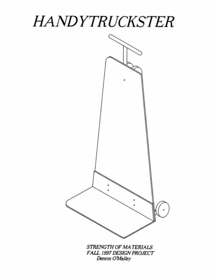
truck 3 - esm intranet site
TRANSCRIPT

4
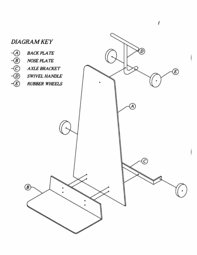
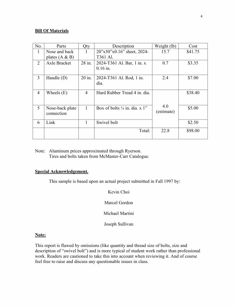
Bill Of Materials No. Parts Qty Description Weight (lb) Cost 1 Nose and back
plates (A & B) 1 20”x50”x0.16” sheet, 2024-
T361 Al. 15.7 $41.75
2 Axle Bracket 28 in. 2024-T361 Al. Bar, 1 in. x 0.16 in.
0.7 $3.35
3 Handle (D) 20 in. 2024-T361 Al. Rod, 1 in. dia.
2.4 $7.00
4 Wheels (E) 4 Hard Rubber Tread 4 in. dia. $38.40
5 Nose-back plate connection
1 Box of bolts ¼ in. dia. x 1” $5.00
6 Link 1 Swivel bolt
4.0 (estimate)
$2.50
Total: 22.8 $98.00
Note: Aluminum prices approximated through Ryerson. Tires and bolts taken from McMaster-Carr Catalogue. Special Acknowledgement. This sample is based upon an actual project submitted in Fall 1997 by:
Kevin Choi
Marcel Gordon
Michael Martini
Joseph Sullivan Note: This report is flawed by omissions (like quantity and thread size of bolts, size and description of “swivel bolt”) and is more typical of student work rather than professional work. Readers are cautioned to take this into account when reviewing it. And of course feel free to raise and discuss any questionable issues in class.
5
Methods
To start our design, we selected a list of materials based upon strength and cost
and selected aluminum for the structural components because it has a good strength-to-
weight ratio compared to steel and it is readily available. Within the aluminum family, we
chose a stronger alloy in order to reduce the size of members and exploit strength to
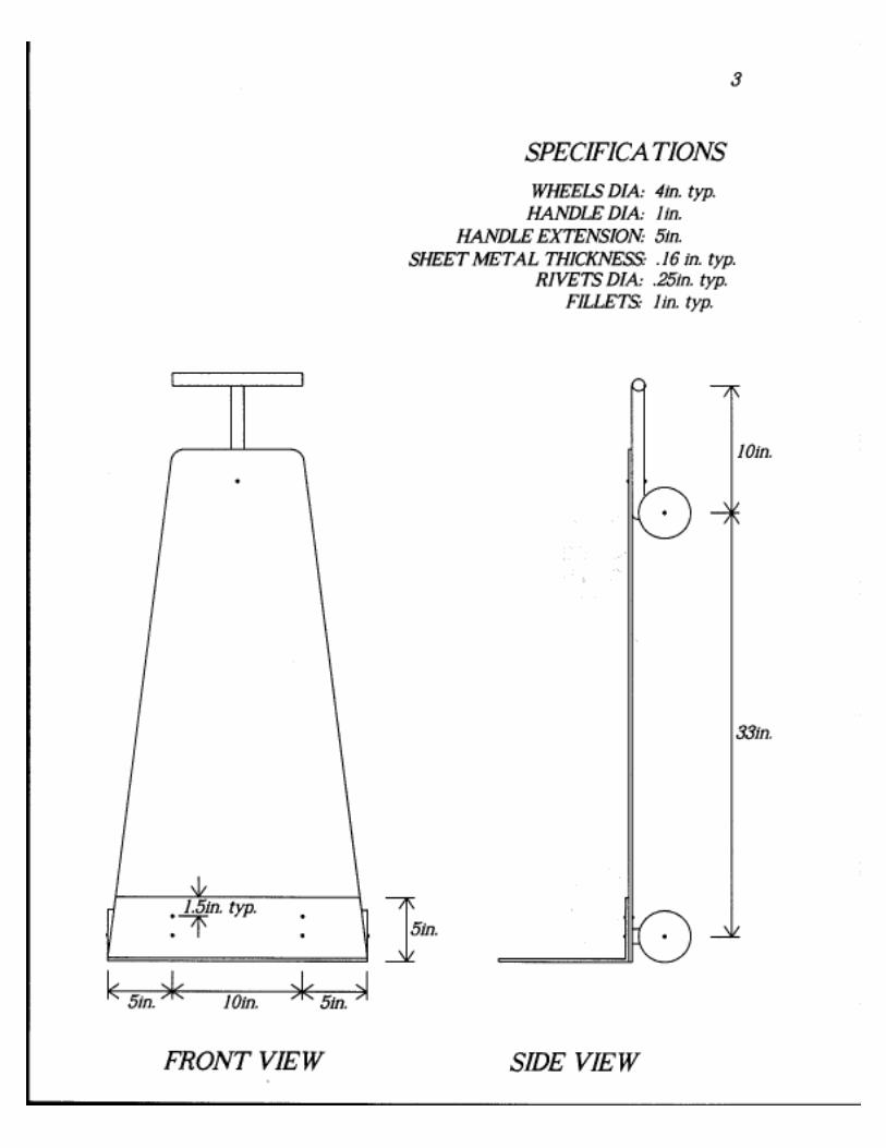
weight, hence create an efficient design. We bolted the back plate to the nose plate
(instead of welding them together) so that the product could be shipped in a flat box. The
handle functions as an extension to the bed in ‘cart mode’ and functions as usual in
upright mode. The rubber wheels are gentle on floors and absorb shock. The analysis
employed strength of materials, but did not include an advanced theory for the plates. The
design was given a distinctive shape to distinguish it from the competition, yet not limit
its function.

6
Assumptions
1. The shear yield stress of ASTM A36 Steel can be approximated by taking 60% of
the tensile yield stress based upon comparison of data found for other steels.
2. The shear yield stress of Aluminum 2024-T361 can be approximated by taking
60% of the tensile yield stress based upon comparison of data found for other
aluminum alloys.
3. Beam theory applies to the plate structure.
Warnings
1. Wheels themselves were not designed.
2. Weld not analyzed.
3. Swivel attachment of handle not analyzed.
7
References
“Corrosion Resistance” (Dennis McCrosky), http://www.strongtie.com/Sstcrpg1.htm Simpson Strong-Tie Company, Inc. Viewed (13 Nov. 1997) “Corrosion Resistance Construction Hardware” (No Author), http://www.hughesmfg.com/Page-45.htm Hughes Manufacturing, Inc. Viewed (17 Nov. 1997) “Mechanical Properties of Some Materials” http://www-dmso.mit.edu/data/mech/prop-file.html Viewed (24 Nov. 1997) Hibbler, R.C. (1994) Mechanics of Materials. Engle Wood Cliffs: Prentice Hall. Ryerson Stock List and Data Book (1987-89) Joseph T. Ryerson & Son Inc., Pittsburgh, PA
8
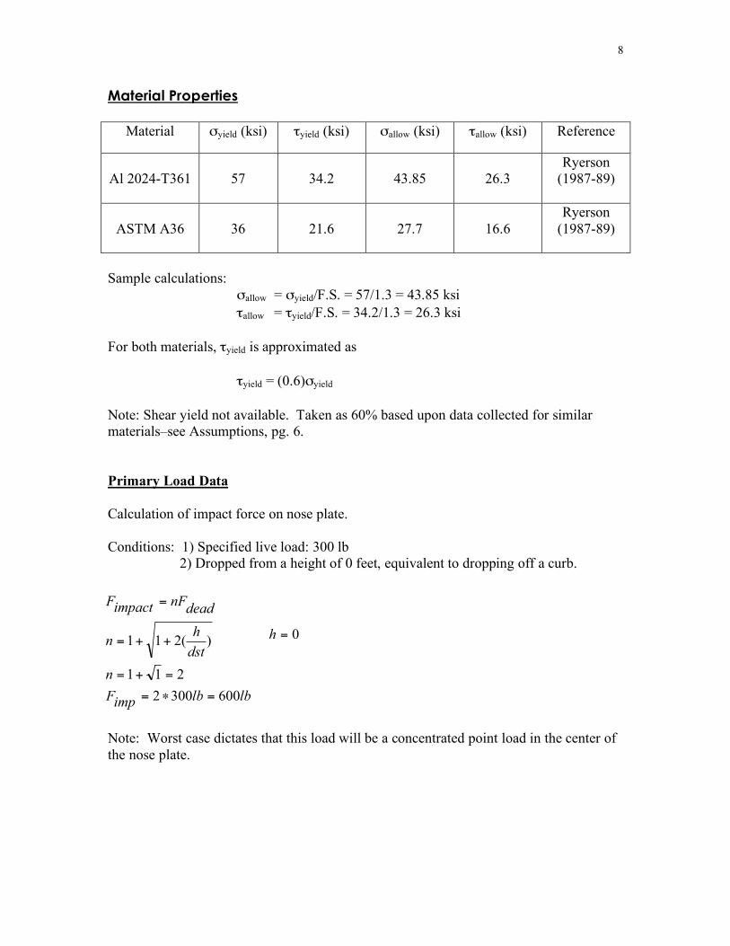
Material Properties
Material σyield (ksi) τyield (ksi) σallow (ksi) τallow (ksi) Reference
Al 2024-T361
57
34.2
43.85
26.3
Ryerson (1987-89)
ASTM A36
36
21.6
27.7
16.6
Ryerson (1987-89)
Sample calculations: σallow = σyield/F.S. = 57/1.3 = 43.85 ksi τallow = τyield/F.S. = 34.2/1.3 = 26.3 ksi For both materials, τyield is approximated as τyield = (0.6)σyield Note: Shear yield not available. Taken as 60% based upon data collected for similar materials–see Assumptions, pg. 6. Primary Load Data
Calculation of impact force on nose plate. Conditions: 1) Specified live load: 300 lb 2) Dropped from a height of 0 feet, equivalent to dropping off a curb.
Note: Worst case dictates that this load will be a concentrated point load in the center of the nose plate.
lblbimpF
n
dst
hn
deadnFimpactF
6003002
211
)(211
=!=
=+=
++=
=
0=h


9
Calculations
Nose Plate
Model: Cantilever beam.
Free-Body Diagram: Cross section Calculation for nose plate.
Bending analysis, determining minimum thickness, t:
Shear analysis:
Z
z
allI
yM ?=! ksi
all85.43=!
2
ty =
� = 0yF lbV 600= � = 0z
M inlbinlbM ?=!= 30005600
3
12
1wtI
z=
inw 20=in
in
lb
lbin
w
Mt
all 202
43850
300066min
!
"!==
#
int 143.0min
=
226300
in
lb
wI
VQ
x
all ==! lbV 600=
824
2wt
wtt
Q =!!=3
12
1wtI
x= inw 20=
226300)12/20(
8/600
12
8/min
in
lbin
lb
w
Vt
all
!=
!
=
"int 0017.0
min=
V
M 5 in.
Y
X
600 lb
600 lb
5 in
w t
10
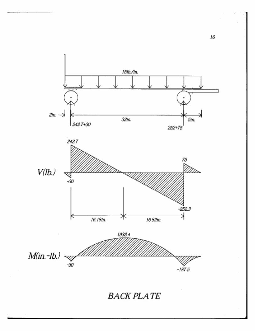
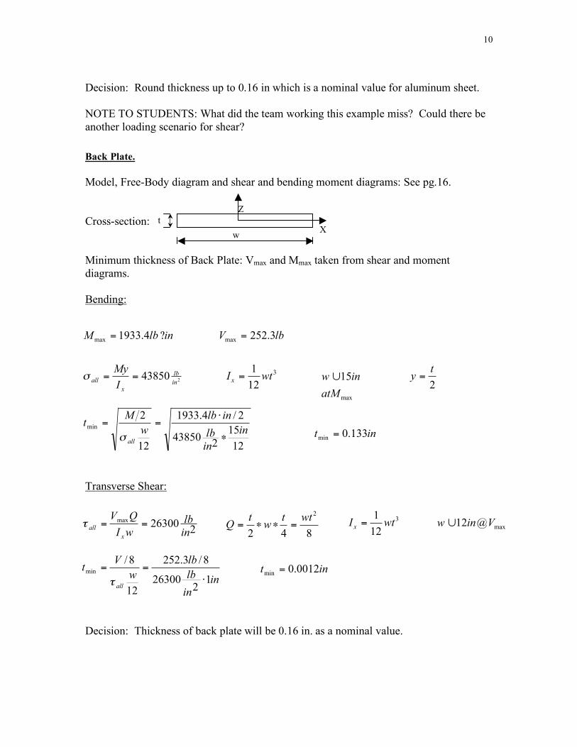
Decision: Round thickness up to 0.16 in which is a nominal value for aluminum sheet. NOTE TO STUDENTS: What did the team working this example miss? Could there be another loading scenario for shear? Back Plate. Model, Free-Body diagram and shear and bending moment diagrams: See pg.16. Cross-section: Minimum thickness of Back Plate: Vmax and Mmax taken from shear and moment diagrams. Bending:
Transverse Shear:
Decision: Thickness of back plate will be 0.16 in. as a nominal value.
inlbM ?= 4.1933max
lbV 3.252max
=
243850
in
lb
x
allI
My==!
3
12
1wtI
x=
max
15
atM
inw !
12
15
243850
2/4.1933
12
2
minin
in
lb
inlb
w
Mt
all!
"==
# int 133.0min
=
2
ty =
226300
max
in
lb
wI
QV
x
all ==!842
2wtt
wt
Q =!!=3
12
1wtI
x=
max@12 Vinw !
in
in
lb
lb
w
Vt
all1
226300
8/3.252
12
8/min
!==
"
int 0012.0min
=
Z
X t
w

11
Axle Bracket. Model: Cantilever beam (wall on left). Free-Body Diagram:
Note: Assume tipping eminent, so that wheel and axle absorb entire load. For simplification in design, setting x=3.0 in. Determine y dimension:
Bending stress analysis, solving for minimum y:
Transverse Shear: Cross-section:
Decision: Round y up to 1 in. nominal. Note that y-min is smaller than the chosen diameter for the wheels. Otherwise modifications would be necessary. Also note that x, or thickness, can be solved for instead of y.
R=2in.
V
F=300lb
M
y
x
Thickness, t=0.16in.
into paper
Y
X
Z
� == lbVFy 300;0 � ?=!== lbininlbMMz
9003300;0
( )2
438502/
in
lb
I
yM
z
all =!
="3
12
1tyI z = t
My
all !=
"
6min
inin
lb
lbiny
16.02
43850
9006min
!
"!= iny 88.0
min=
226300
in
lball=!
tI
VQ
z
all =!3
12
1tyI z =
inin
in
lb
inlb
t
Vty
all
156.0
12/16.02
26300
8/25.03008/
222
12
1min=
!
!==
"
Z
Y
t
y
824
2ty
tyy
Q =!!=
12
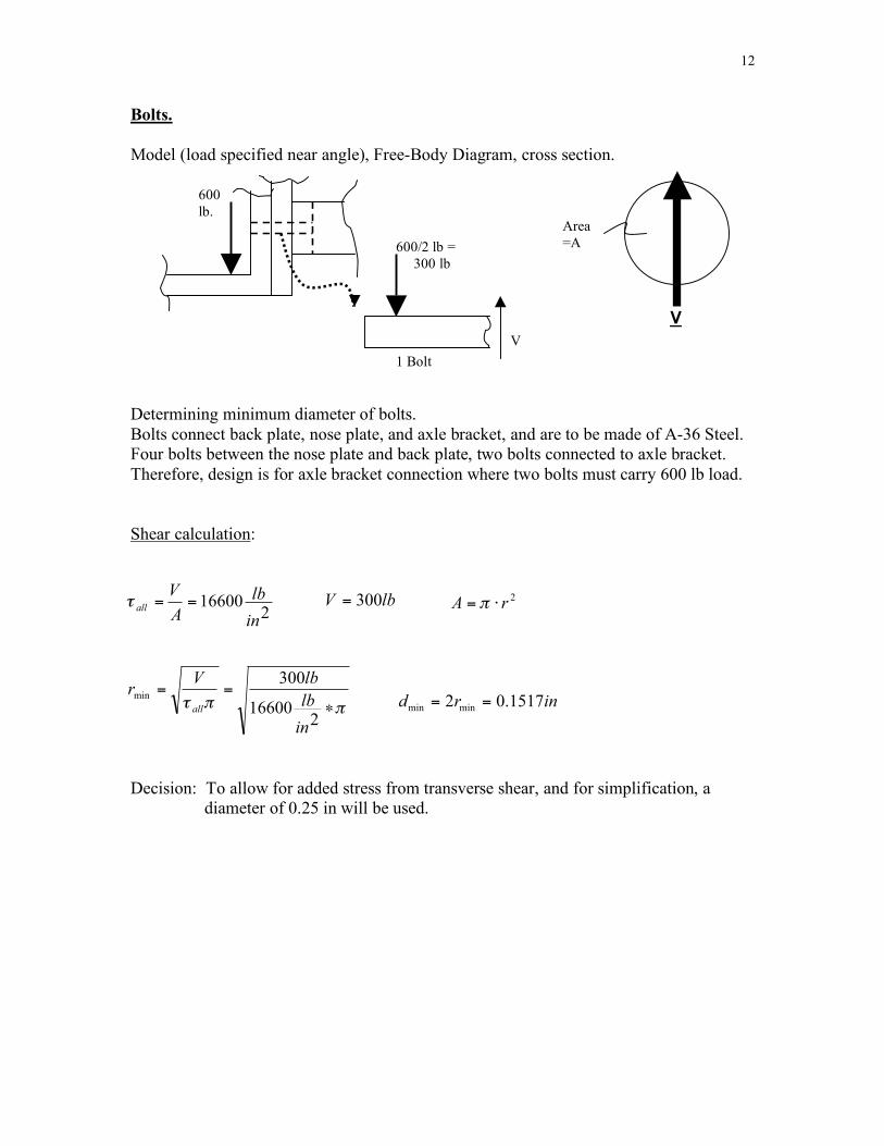
Bolts. Model (load specified near angle), Free-Body Diagram, cross section. Determining minimum diameter of bolts. Bolts connect back plate, nose plate, and axle bracket, and are to be made of A-36 Steel. Four bolts between the nose plate and back plate, two bolts connected to axle bracket. Therefore, design is for axle bracket connection where two bolts must carry 600 lb load. Shear calculation:
Decision: To allow for added stress from transverse shear, and for simplification, a
diameter of 0.25 in will be used.
V
Area=A
216600
in
lb
A
Vall
==! lbV 300= 2rA != "
!!" #==
216600
300min
in
lb
lbVr
allinrd 1517.02
minmin==
600 lb.
1 Bolt
600/2 lb = 300 lb
V
13
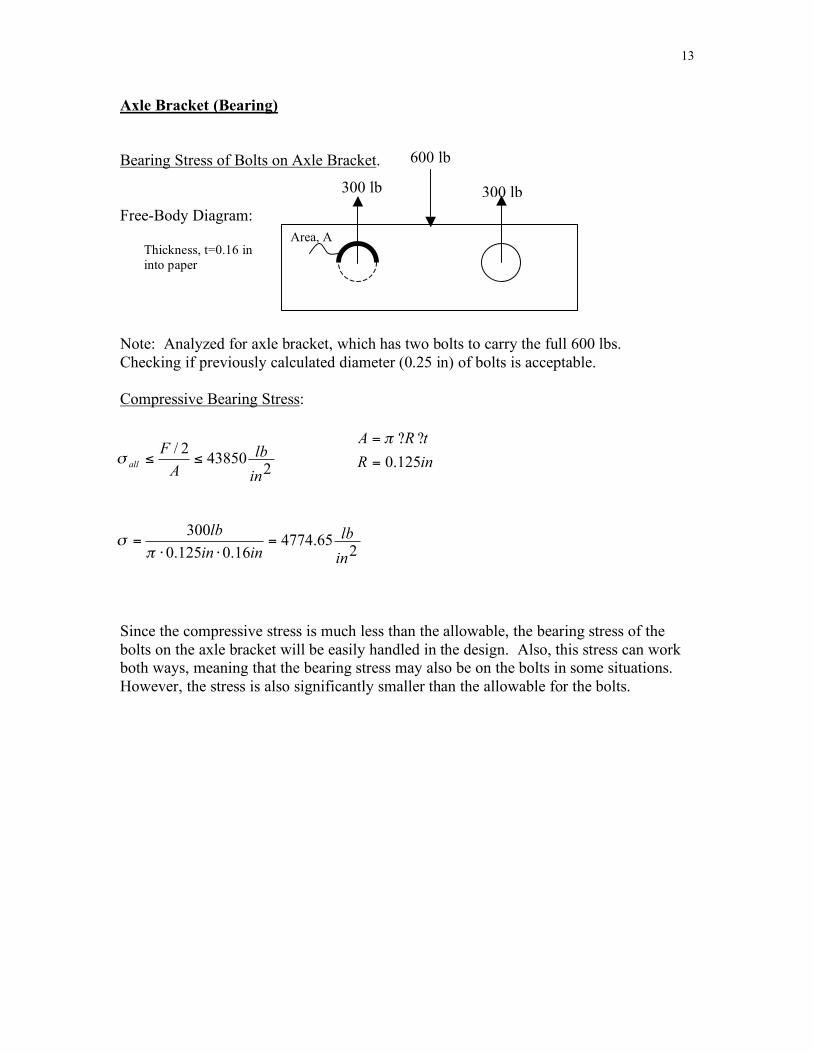
Axle Bracket (Bearing) Bearing Stress of Bolts on Axle Bracket. Free-Body Diagram: Note: Analyzed for axle bracket, which has two bolts to carry the full 600 lbs. Checking if previously calculated diameter (0.25 in) of bolts is acceptable. Compressive Bearing Stress:
Since the compressive stress is much less than the allowable, the bearing stress of the bolts on the axle bracket will be easily handled in the design. Also, this stress can work both ways, meaning that the bearing stress may also be on the bolts in some situations. However, the stress is also significantly smaller than the allowable for the bolts.
600 lb
Area, A
300 lb 300 lb
243850
2/
in
lb
A
Fall
!!" inR
tRA
125.0=
??= !
265.4774
16.0125.0
300
in
lb
inin
lb=
!!="
#
Thickness, t=0.16 in into paper
14
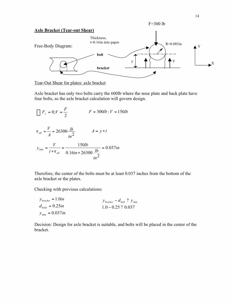
Axle Bracket (Tear-out Shear) Free-Body Diagram:
Tear-Out Shear for plates: axle bracket
Axle bracket has only two bolts carry the 600lb where the nose plate and back plate have four bolts, so the axle bracket calculation will govern design.
Therefore, the center of the bolts must be at least 0.037 inches from the bottom of the axle bracket or the plates. Checking with previous calculations:
Decision: Design for axle bracket is suitable, and bolts will be placed in the center of the bracket.
bolt
F=300 lb
y
R=0.085in Y
X
� ==2
;0F
VFy lbVlbF 150:300 ==
226300
in
lb
A
Vall
==!
Thickness, t=0.16in into paper
tyA !=
in
in
lbin
lb
t
Vy
all
037.0
22630016.0
150min
=!
=!
="
iny
ind
iny
bolts
bracket
037.0
25.0
0.1
min=
=
=
037.025.00.1
min
?!
?! ydy boltbracket
V
bracket