truck accessories - transairvac international ltd ... f01- f02- vp1.pdf · 10-3- 5 parker hannifin...
TRANSCRIPT

F1plus_access.epsLeif A./00-07-07
1
3
2
NOR
MA
LR
UN
NIN
GCHANGE FILTER
R L
ROTATION
aerospaceclimate controlelectromechanicalfiltrationfluid & gas handlinghydraulicspneumaticsprocess controlsealing & shielding
Truck AccessoriesFittings, Adaptor kits and accessories for F1, F2, T1 and VP1 pumps

10-3- 2 Parker Hannifin CorporationHydraulics Group
Catalogue HY02-8001/UK
Catalogue HY30-8200/UK. 12/2011
Conversion factors1 kg ................................................................. 2.20 lb
1 N ............................................................... 0.225 lbf
1 Nm ......................................................... 0.738 lbf ft
1 bar ..............................................................14.5 psi
1 l ......................................................0.264 US gallon
1 cm3 ........................................................0.061 cu in
1 mm ............................................................. 0.039 in9/5 °C + 32 ............................................................1°F
1 kW .............................................................. 1.34 hp
Truck HydraulicsContents
Contents Page 10-3-
FittingsSuction fittings for series F1, F2 and T1 pumps also VP1-095 and -120 ........3Fitting kits for VP1-045 and -075 pumps ........................................................4
Auxiliary ValvesBypass ValvesBPV-F1 and BPV-T1 bypass valve .................................................................5Ordering information and Drawings ................................................................6BPV-F1 and BPV-T1 Bypass valve without manual override ..........................6BPV-F1 Bypass valve with manual override ...................................................6BPV-F2 bypass valve ......................................................................................7Ordering information and Drawings ................................................................8BPV-F2 Bypass valve without manual override ..............................................8BPV-F2 Bypass valve with manual override ...................................................9BPV-F1, -T1 and F2 Accessories / Spare Parts ...........................................10
Unloading ValvesBPV-L line mounted bypass valve ................................................................11BPV-VP1 unloading valve .............................................................................12
AccessoriesAir valve kit for Volvo PTO's ..........................................................................14Universal PTO air valve kit ............................................................................14
PTO Adapter KitsPTO adapter kit for Scania ED 120 engines ................................................15PTO adapter kit for Scania ED 160 engines ................................................16PTO adapter kit for Mercedes engines (R6) .................................................17PTO adapter kit for Mercedes engines (V6, V8) ...........................................17PTO adapter kit for MAN (D20, D26, D28) ...................................................17Cardan shafts, pump couplings and mounting brackets ..............................18Cardan shaft specifications ..........................................................................18PTO flange adapters ....................................................................................18Pump couplings ............................................................................................19SB splitter boxes ...........................................................................................20Through-shaft coupling VP1-045/075 ...........................................................21
10-3- 3 Parker Hannifin CorporationHydraulics Group
Catalogue HY02-8001/UK
10
Truck HydraulicsFittings
Suction_fittings_F1plus_GB.epsLeif A./020115
C
C
C
C
A
A
A
B
B
B
A
B
Suction fitting
Cap screw Hold-down clamp
O-ring‘Straight’ fitting
45° fitting
90° fitting
145° fitting
19.5
19.5
19.5
19.5
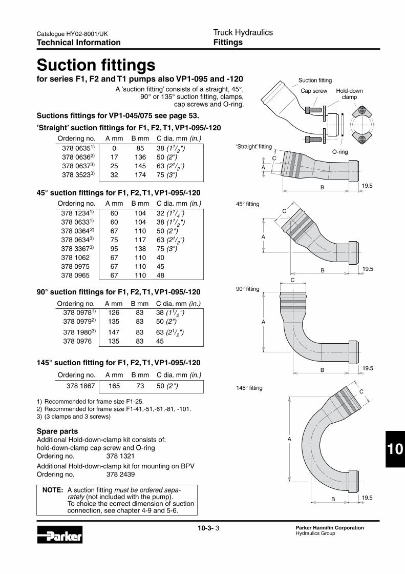
Ordering no. A mm B mm C dia. mm (in.) 378 09781) 126 83 38 (11/2") 378 09792) 135 83 50 (2")
378 19803) 147 83 63 (21/2") 378 0976 135 83 45
Ordering no. A mm B mm C dia. mm (in.) 378 06351) 0 85 38 (11/2") 378 06362) 17 136 50 (2") 378 06373) 25 145 63 (21/2") 378 35233) 32 174 75 (3")
Suction fittingsfor series F1, F2 and T1 pumps also VP1-095 and -120
Suctions fittings for VP1-045/075 see page 53.
’Straight’ suction fittings for F1, F2, T1, VP1-095/-120
Ordering no. A mm B mm C dia. mm (in.) 378 12341) 60 104 32 (11/4") 378 06331) 60 104 38 (11/2") 378 03642) 67 110 50 (2 ") 378 06343) 75 117 63 (21/2") 378 33673) 95 138 75 (3") 378 1062 67 110 40 378 0975 67 110 45 378 0965 67 110 48
45° suction fittings for F1, F2, T1, VP1-095/-120
90° suction fittings for F1, F2, T1, VP1-095/-120
Ordering no. A mm B mm C dia. mm (in.)
378 1867 165 73 50 (2 ")
145° suction fitting for F1, F2, T1, VP1-095/-120
A ’suction fitting’ consists of a straight, 45°, 90° or 135° suction fitting, clamps,
cap screws and O-ring.
NOTE: A suction fitting mustbeorderedsepa-rately (not included with the pump).To choice the correct dimension of suction connection, see chapter 4-9 and 5-6.
Spare partsAdditional Hold-down-clamp kit consists of: hold-down-clamp cap screw and O-ring Ordering no. 378 1321
Additional Hold-down-clamp kit for mounting on BPV Ordering no. 378 2439
1) Recommended for frame size F1-25. 2) Recommended for frame size F1-41,-51,-61,-81, -101. 3) (3 clamps and 3 screws)
Technical Information

10-3- 4 Parker Hannifin CorporationHydraulics Group
Catalogue HY02-8001/UK
Nipplar_ny.epsLeif A./05-01-21
13 C
ØA
ØB
ØB
ØA
44 13
C
Suitable suction adapters for F1 with BSP port treads
45° adapter Ordering no. A* B C
00509035016 1" 2" 18 00509035116 11/4" 2 " 18 00509021916 11/4" 21/2" 18
* BSP threads
90° adapter Ordering no. A* B C
00509034516 1" 2" 18 00509034616 11/4" 2" 18
* BSP threads
C2
C2
C2
C1
C1
C1
Fittings_install_GB.epsLeif A./020115
A
B
A
B
Pressure fitting
45° adjustable suction fitting
Fitting kits for VP1-045 and -075 pumps
Kits with 45° suction fitting Pump size Ordering no. C1 ØC2 A B
VP1-045/075 379 9563 BSP 3/4" 2" 71 154 VP1-045/075* 379 9562 BSP 1" 21/2" 64 147
* Above 100 l/min
NOTE: A suction fitting mustbeorderedsepa-rately (not included with the pump).To choice the correct dimension of suction connection, see 4-9 and 5-6
Truck HydraulicsFittingsTechnical Information

10-3- 5 Parker Hannifin CorporationHydraulics Group
Catalogue HY02-8001/UK
10
Truck HydraulicsAuxiliary valves
BPV_F1_schematic.epsLeif A./020114
’q’
Pilot operated check valve
Solenoid valve
Directional control valve (‘open centre’)
F1 pump Valve block Drain port (External line)
BPV-F1 and BPV-T1 bypass valve• The bypass valve is mainly utilised in applications
where the F1 pump is driven from the crank-shaft through a cardan shaft, or when it is installed on an engine PTO.
• The BPV bypass valve should be engaged during transportation when the pump is operating cons- tantly and the engine is running at max rpm; the hydraulic system is not sized for the large flow that would otherwise go through it.
• The BPV valve substantially reduces the energy loss during transportation.
• The valve installs directly on top of the pump end cap with a pressure port ’banjo’ fitting and an inlet port spacer bushing with two cap screws; refer to the illustration to the right.
• As the BPV valve is symmetrical, it can be ’turned 180°’ to prevent interference with chassis compo- nents; it can be utilised for either left hand or right hand pumps.
• The valve function must only be activated or released (by means of the 24 VDC solenoid)
at no-load(below 20 bar) systempressure.
IMPORTANT INFORMATION- In order to prevent heat build-up in the pump
during transportation, it is important that at least 5 l/min comes out of the filter at ’q’ (refer to the schematic). This applies to an ’open center’ system when the valve is in the bypass mode (non-activated solenoid).
- Pleasenote: a) Iftheflowat’q’islessthan5l/min(causede.g.by
ahighpressuredropinthemainsystem)whenthevalveisinthebypassmode,or
b) ifthehydraulicsystemisofthe’closedcenter’type,thenanexternaldrainlinemust be installed fromthebypassvalvedrainportdirectlytotankasshownintheschematic;adrainkitisavailable(seenextpage).
Bypassvalveschematic.
Pump pressure portPump suction port
Pressure connector
Valve body
O-ring (x2)
(F1 end cap)
Suction adapter
Hold-down clamp (x2)
O-ring (x3)
Spacer bushing
39 (39)
BSP 1"(BSP 3/4")
NoteThe bypass valve is available in two versions, one with and one without manual override. The solenoid cartridge with manual override can not be installed in valve blocks designed for solenoid cartridge without manual override and vice versa because of the solenoid cartridges different connection threads.
Ordering information and DrawingsSee next page.
Technical Information

10-3- 6 Parker Hannifin CorporationHydraulics Group
Catalogue HY02-8001/UK Truck HydraulicsAuxiliary valves
Ventilblock_09-02-05.aiLeif A.
105 (103)
110(109)
BPV-F1and-T1installationandcrosssectionwithoutmanualoverride
NOTE: Dimensions are shown for BPV-F1-81 (those for BPV-F1-25 are in parenthesis)
IMPORTANT:Always tighten the pressure connector before tighten-ing the cap screws.Also, see table to the left.
IMPORTANT:Always tighten the pressure connector before tighten-ing the cap screws.Also, see table to the left.
Valve housing
Drain port (plugged); BSP 1/4"
Hold-down clamp (x2)
Cap screw (x2)
Valve housing
Drain port (plugged); BSP 1/4"
Hold-down clamp (x2)
Cap screw (x2)
Solenoid valve
Solenoid valve
Connector(included)
Connector(included)
BPV-F1installationandcrosssectionwithmanualoverride
Ventilblock_11-10-24.aiLeif A.
105 (103)
110(109)
Anm.: Mått visade för BPV-F1-81 (inom parentes för BPV-F1-25 ).
Manual override
BPV-F1 Bypass valveWith manual override
Bypassvalve kits
Voltage Orderingnumber
For F1 size Torque1)
BPV-F1-25, 24 VDC 378 7461 F1-25, -41, -51 and -61
50 Nm
BPV-F1-81, 24 VDC 378 7462 F1-81 and -101
100 Nm
Drain fitting kit F1-025
378 1640 Contains a drain line fitting a bonded seal and nozzle.
Drain fitting kit other F1, F2
378 3039 Contains a drain line fit-ting and a bonded seal.
1) Torque pressure connector to:
Bypassvalve kits
Voltage Orderingnumber
For F1 and T1 size
Torque1)
BPV-F1-25 24 VDC 378 8803 F1-25 50 Nm
BPV-F1-41, BPV-T1-81
24 VDC 12 VDC
378 7201 378 7202
F1-41, -51, -61 and T1-81
50 Nm
BPV-F1-81, BPV-T1-121
24 VDC 12 VDC
378 7203 378 7204
F1-81, -101 and T1-121
100 Nm
Drain fitting kit F1-025
378 1640 Contains a drain line fitting a bonded seal and nozzle.
Drain fitting kit other F1, F2 and T1
378 3039 Contains a drain line fit-ting and a bonded seal.
1) Torque pressure connector to:
Bypass valve, type BPV-F1-25 and -81Max pressure, continuous 350 barintermittent 400 bar Solenoid voltage 24 VDCPower requirement 17 WOperating mode Activated solenoid:
Check valve closed
Bypass valve, type BPV-F1-25 to -101 and BPV-T1-81 and -121
Max pressure, continuous 350 barintermittent 400 bar Solenoid voltage (option) 24 VDC, (12VDC)Power requirement 17 WOperating mode Activated solenoid:
Check valve closed
BPV-F1 and BPV-T1 Bypass valveWithout manual override
Ordering information and Drawings

10-3- 7 Parker Hannifin CorporationHydraulics Group
Catalogue HY02-8001/UK
10
BPV_F2plus_schem_GB.epsLeif A./000323
A
B
BPV-F2
F2-twin-flow pump
Solenoid valve (24 or 12 VDC)
Directional control valves (‘open centre’)
Pilot operated check valve
Separate drain line
Bypassvalvecircuitschematic(example).
BPV-F2 bypass valve• An F2 twin pump fitted with a bypass valve can be
utilised in applications where the pump is operating constantly i.e. when the pump is driven from the crank- shaft through a cardan shaft, or when it is installed on an engine-PTO. In addition, it can be used when, temporarily, one of the two circuits is not required; the power loss is thus reduced as the non-required flow is not forced through lines and ’open center’ valves.
• The BPV bypass valve should be engaged during transportation when the pump is operating cons- tantly and the engine is running at max rpm; the hydraulic system is not sized for the large flow that would otherwise go through it.
• The BPV valve connects the outlet and inlet ports of the pump, and only a small oil flow goes through the system and to the reservoir.
• The valve is installed directly on top of the pump port surface with ’banjo’ fittings and two cap screws (refer to the split view to the right).
• As the BPV valve is symmetrical it can be ’turned 180°’ so as not to interfere with chassis components.The valve can accommodate left hand as well as right hand rotating pumps.
• The valve can only be engaged or disengaged ( through the 24 or 12 VDC solenoid) at low system pressures (below 20 bar).
IMPORTANT INFORMATION- In order to secure a cooling flow through the system,
a separate drain line must be connected from the BPV-F2 drain line fitting (shown in the split view) directly to tank; refer also to the schematic.
- The pressure connectors must be tightened (to 50 Nm) before the suction fitting clamp screws are tightened.
Truck HydraulicsAuxiliary valves
NoteThe bypass valve is available in two versions, one with and one without manual override. The solenoid cartridge with manual override can not be installed in valve blocks designed for solenoid cartridge without manual override and vice versa because of the solenoid cartridges different connection threads.
Ordering information and DrawingsSee next page.
Technical Information

10-3- 8 Parker Hannifin CorporationHydraulics Group
Catalogue HY02-8001/UK Truck HydraulicsAuxiliary valves
BPV_F2_split_09-02-05.aiLeif A.
O-ring (x4) 1)
1) The BPV-F2 valve kit contains parts designated ’1’ in the split view to the right.
2) A suction fitting kit (parts designated ’2’ in the split view) is not included with the F2 pump; it must be ordered separately (refer to chapter10).
3) Torque pressure connector to:
Bypassvalve kits1)
Voltage Orderingnumber
For F2 size Torque3)
BPV-F2, 24 VDC12 VDC
378 7424378 7425
42/42, 53/53, 55/28, 70/35, 70/70
50 Nm
‘1’-BPV-F2 valve kit
Capscrew1)
Pressure connector (x2) 1)
‘2’- Suction fitting kit
Suctionfitting2)
Hold-downclamp(x2)1)
Drain line (not included) to be connected directly to tank
O-ring2)
Drain line fitting1)
(BSP 1/4")
Bonded seal 1)
Valve blocksub-assy 1)
Solenoid valve (x2) 1); (connector included)
Plug with bonded seal1)
Spacer bushing 1)
O-ring (x2) 1)
Bypassvalvesplitviewwithoutmanualoverride(withF2endcap).
NOTE: A suction fitting kit (parts designated ’2’ in the split view) is not included with the F2 pump; it must be ordered separately (refer to chapter10).
BPV-F2 Bypass valveWithout manual override
Ordering information and Drawings
Bypass valve, type BPV-F2Max pressure, continuous 350 barintermittent 400 bar Solenoid voltage (option) 24 VDC, (12VDC)Power requirement 17 W (each solenoid)Operating mode Activated solenoid:
Check valve closed

10-3- 9 Parker Hannifin CorporationHydraulics Group
Catalogue HY02-8001/UK
10
Truck HydraulicsAuxiliary valves
1) The BPV-F2 valve kit contains parts designated ’1’ in the split view to the right.
2) A suction fitting kit (parts designated ’2’ in the split view) is not included with the F2 pump; it must be ordered separately (refer to chapter10)..
3) Torque pressure connector to:
Bypassvalve kits1)
Voltage Orderingnumber
For F2 size Torque3)
BPV-F2, 24 VDC 378 7463 42/42, 53/53, 55/28, 70/35, 70/70
50 Nm
BPV_F2_split_11-10-24.aiLeif A.
O-ring (x4) 1)Manual override
‘1’-BPV-F2 valve kit
Capscrew1)
Pressure con- nector (x2) 1)
‘2’- Suction fitting kit
Suctionfitting2)
Hold-downclamp(x2)1)
Drain line (not included) to be connected directly to tank
O-ring2)
Drain line fitting1)
(BSP 1/4")
Bonded seal 1)
Valve blocksub-assy 1)
Solenoid valve (x2) 1); (connec-tor included)
Plug with bonded seal1)
Spacer bushing 1)
O-ring (x2) 1)
Bypassvalvesplitviewwithmanualoverride(withF2endcap).
NOTE: A suction fitting kit (parts designated ’2’ in the split view) is not included with the F2 pump; it must be ordered separately (refer to chapter10).
BPV-F2 Bypass valveWith manual override
Ordering information and Drawings
Bypass valve, type BPV-F2Max pressure, continuous 350 barintermittent 400 bar Solenoid voltage 24 VDCPower requirement 17 W (each solenoid)Operating mode Activated solenoid:
Check valve closed

10-3- 10 Parker Hannifin CorporationHydraulics Group
Catalogue HY02-8001/UK Truck HydraulicsAuxiliary valvesTechnical Information
Solenoid
Cartridge valve assy
Inlet union screw
O-ring
Flange clamp 1)Part No Description Remarks
3781480 Inlet union screw F2 (all sizes)
3781082 Inlet union screw F1-25, -41, -51, -61
3781094 Inlet union screw F1-81, -101
3780641 O-ring kit For both F1 and F2 (all sizes)
3782439 Hold-down clamp Suction fitting 1)
For BPV F1 and F2
1) Hold-down clamp for suction fitting on bypass valve for F1, T1 and F2 (parts designated ’1’ in the split view).
Part No Description Remarks
3787496 Solenoid 24V Incl. new connector
3787497 Solenoid 12V Incl. new connector
3787494 Cartridge valve assy 24V
Without manual override
3787495 Cartridge valve assy 12V
Without manual override
3785948 Nut for cartridge valve
3787488 Male contact kit
Part No Description Remarks
3788663 Cartridge valve assy 24V
With manual override
BPV-F1, -T1 and F2 Accessories / Spare Parts
NoteThe bypass valve is available in two versions, one with and one without manual override. The solenoid cartridge with manual override can not be installed in valve blocks designed for solenoid cartridge without manual override and vice versa because of the solenoid cartridges different connection threads.
Screw 1)
O-ring 1)
Male contact kit
Nut

10-3- 11 Parker Hannifin CorporationHydraulics Group
Catalogue HY02-8001/UK
10
Unloading valve, type BPV-L
Max operating pressure [bar] 350
Max flow [l/min] 250
Solenoid voltage [VDC] 24
Required power [W] 17
Operating mode Activated solenoid: Check valve closed
Ordering number 378 1487
BPV-L line mounted bypass valve• The unloading valve BPV-L is utilised in hydraulic
systems where the fixed displacement pump is en-gaged constantly and no flow is required, i.e. during transportation. The flow is directed through the un-loading valve which has a low pressure loss and less heat is being generated in the system.
• When the solenoid is activated the unloading valve closes and the pump flow is directed to the directional control valve or other user.
Truck HydraulicsAuxiliary valves
BPV_L_schematic_GB.epsLeif A./020115
Unloading valve
Gauge port ‘G’
Directional control valve (‘open centre’)
Solenoid valve
100
6245
4510 10
100
BSP 1"(x2)
φ 9(x2)
50
'IN'
'UT'
BPV_L_install_09-02-05.aiLeif A.
Solenoid valve (24 VDC standard);connector included
Gauge port (BSP 1/4")
Technical Information

10-3- 12 Parker Hannifin CorporationHydraulics Group
Catalogue HY02-8001/UK
51.5 32
8.5
4192
9�4030
53 φ 6.5(x2)
T P
SX
BPV-VP1_unloading_valve.aiLeif A./09-04-15
4 mm hex key
BSP 1/4"(x3)
BPV-VP1 unloading valve
BPV-VP1-045-075_schematic.aiLeif A./09-04-15
SX
TP
Load sensing
valve
Load sensing (LS) line
VP1-045or -075pump
BPV-VP1 unloading
valve (5 bar)
Fittingwith orifice (included)
VP1-45-75_ports.aiLeif A./09-04-15
Port T (BSP 1/4") Must be connected directly to tank! Port LS (BSP 1/4")
Pressure port (BSP 1")
Suction port (BSP 1 1/4")
Port M (BSP 1/4")
Truck HydraulicsAuxiliary valves
BPV-VP1unloadingvalve.
BPV-VP1installationschematicwithVP1-45/ -75pump.
VP1-45/ -75endview(showingports).
BVP-VP1 with VP1-45/75 pumps
NOTE: - Install the fitting (included) in port M and connect it, in turn, to port S of the unloading valve (see schematic). - An orifice is inclu- ded in the fitting.
For more information also see HY30-8226-INST/UK, Installation Information Unloading Valve BPV for VP1
VP1 installation on an engine PTO
BPV-VP1 unloading valveThe BPV-VP1 unloading valve is utilized in hydraulic systems where the pump is in constant operation. The valve protects the pump from being overheated in the off-load mode by allowing a small flow through the pump. When load sensing valve function is engaged, the bypass flow is cut off (as port ‘X’ is being pressurized).
The valve will also de-air the suction line and the pump body after a long standstill.
(The pump is assembled above the oil-tank and dur-ing the standstill some of the oil in the pump housing has been drained back to the oil-tank)
Valve Ordering type number
BPV-VP1 379 8799
NOTE: - BPV-VP1 with VP1-45 or -75, see below - BPV-VP1 with VP1-095 or -120, see next page.
Technical Information

10-3- 13 Parker Hannifin CorporationHydraulics Group
Catalogue HY02-8001/UK
10VP1-120mainports(withfittinginstallation).
VP1-095mainports(withfittinginstallation).
VP1-095controlvalveports.
Truck HydraulicsAuxiliary valves
BPV-VP1 with VP1-095 pumps
BPV-VP1 with VP1 -120 pumps.
VP1-095_ports.aiLeif A./09-04-15
Port M (BSP 1/4")Install fitting!
Pressure port (BSP 1")
Suction port (special suction port
adapter required)Left hand
rotating pumpRight hand
rotating pump
VP1-095_ports.aiLeif A./09-04-15
Port T (BSP 1/4");Must be connected directly to tank!
Port LS (BSP 1/4")
VP1-120_ports.aiLeif A./09-04-15
A
A
A
A
Pressure port (BSP 1")
Suction port*
Port M (BSP 1/4")Install fitting!
Left hand rotating pump
Right hand rotating pump
VP1-120_ports.aiLeif A./09-04-15
A
A
A
A
Port T (BSP 3/8");Must be connected directly to tank!
Port LS (BSP 1/4")
View A–A
BPV-VP1-095_schematic.aiLeif A./09-04-15
SM
T
LS X
TP
VP1-095 pump
Nipple with orifice
Load sensing valve
BPV-VP1 unloading
valve (5 bar)
Load sensing (LS) line
BPV-VP1-120_schematic.aiLeif A./09-04-15
MLS S
X
TT P
VP1-120 pump
Load sensing (LS) line
Load sensing
valve
BPV-VP1 unloading
valve (5 bar)
Fitting with orifice (included)
NOTE: - Install the fitting (included) in port M and connect it, in turn, to port S of the unloading valve (see schematic). - An orifice is inclu- ded in the fitting.
NOTE: - Install the fitting (included) in port M and connect it, in turn, to port S of the unloading valve (see schematic). - An orifice is inclu- ded in the fitting.
* special suction port adaproer required
BPV-VP1installationschematicwithVP1-095pump.
BPV-VP1installationschematicwithVP1-120pump.
Technical Information

10-3- 14 Parker Hannifin CorporationHydraulics Group
Catalogue HY02-8001/UK
PTO air valve kit Volvo Air valve nominal voltage [VDC] 24 Nominal current [A] 0.4 Required power [W] 9.6 Max air pressure [bar] 10 Air hose size 1/4" Operating mode Activated solenoid: Air valve open and PTO engaged.
Ordering number, 378 1010 series FM and FH
• The air valve kit is suitable for operating a Volvo PTO on Series FM and FH truck chassis. All parts required to operate the PTO are included in the kit (as shown below).
• The air valve can be combined with other air valves on the chassis; this means a simple installation with a common air supply and a minimum of hoses.
• All electrical wires are pre-installed on the chassis. The relay should be installed in socket K1-14 behind the dashboard cover.
• Function: The relay makes sure the PTO is being disengaged
as soon as the 'ignition key' is turned off. To re-engage the PTO, the operator has to put the
switch back to neutral, and then move it to the 'ON' position.
Air valve kit for Volvo PTO's.
Air valve kit for Volvo PTO's
Truck HydraulicsAccessories
PTO air valve kit Universal
Air valve nominal voltage [VDC] 24 Nominal current [A] 0.4 Required power [W] 9.6 Max air pressure [bar] 10 Air hose size 1/4" Operating mode Activated solenoid: Air valve open and PTO engaged.
Ordering number 370 8779
• The kit includes all parts required for maneouvering the PTO.
• The air valve kit is suitable for most PTO's with a metric M12x1.5 air connection.
• The air valve can be installed with other air valves on the chassis which means simple installation with
common air supply and a minimum of hoses.• The air valve can be connected to electrical wires
usually pre-installed on the chassis.
Universal PTO air valve kit
Technical Information

10-3- 15 Parker Hannifin CorporationHydraulics Group
Catalogue HY02-8001/UK
10
Scania_ED120_adapter_ny2.aiLeif A./06-11-15
Max. torque [Nm] 600 Gear ratio (engine :pump) 1 : 1.19 Pump rotation Right hand (clockwise)
PTO adapter kit Ordering number
ED-90/120-F1/F2, bearing supported (37°) 378 3080 ED-90/120-VP1, bearing supported (22°) 378 3081
PTO adapter kit for Scania ED 120 engines The adapter also fit ED90, motor DC9-11, from September 2004 and later.• With the adapter kit, a hydraulic pump (e.g. F1 or
VP1) that meets the ISO standard can be installed on the PTO of the Scania 12 liter engine.
• The PTO gear is supplied with the chassis.• Please note: The engine must be ordered with a
PTO.
Truck HydraulicsAccessories
NOTE!When used on ED-120 the pump shall be mounted with the connections pointing “up”.(not necessary when the gear in the PTO has a supportbearing)
Gasket between pump and adapter is not included.
Technical Information

10-3- 16 Parker Hannifin CorporationHydraulics Group
Catalogue HY02-8001/UK
Scania_ED160_adapter_ny2.aiLeif A./06-11-15
Max. torque [Nm] 600 Gear ratio (engine :pump) 1 : 1.19 Pump rotation Left hand (counter clockwise)
PTO adapter kit Ordering number
ED-160-F1/F2, bearing supported (37°) 378 3082 ED-160-VP1, bearing supported (22°) 378 3083
PTO adapter kit for Scania ED 160 engines • With the adapter kit, a hydraulic pump (e.g. F1 or
VP1) that meets the ISO standard can be installed on the PTO of the Scania 16 liter engine.
• The PTO gear is supplied with the chassis.• Please note: The engine must be ordered with a
PTO.
Truck HydraulicsAccessories
NOTE!When used on ED-160 the pump shall be mounted with the connections poin-ting “up”.(N.B. only when the gear in the PTO has a supportbearing)
Gasket between pump and adapter is not included.
Technical Information

10-3- 17 Parker Hannifin CorporationHydraulics Group
Catalogue HY02-8001/UK
10
9077
58
777064
62
75
3866
79
3780
6216
A8x32x36DIN 5462
121
D20, D26 D28
19694
39
87 8264
DIN 5462A8x38x36
47
1626
12966 37
80
190
9546
24
9264
PTO adapter kit for Mercedes engines (R6)
Truck HydraulicsAccessories
146
41
80
A8x32x36DIN 5462
10 19
Z24
44.5
54.7
66.16
Ø82
.5
66.16
59.2
72.5
80
75
Z = 16DIN 5480
A8x32x36DIN 5462
146 (5 3/4˝)
For ISO flange, 4 bolts
For SAE “B”,2 bolts
PTO adapter kit for MAN (D20, D26, D28)
With the adapter kit, a hydraulic pump that meets the ISO standard can be installed on the PTO of the Mercedes R6 engines.
Torque continuous 300 NmTorque intermittent 330 NmGear ratio (engine to pump) 1 : 1.071Pump rotation Right handOrdering No. 0050706404
With the adapter kit, a hydraulic pump that meets the ISO standard can be installed on the PTO of the Mercedes V6 and V8 engines.This adapter (7012104), can be fitted on the original DC SAE -A adapter, delivered together with the new ACTROS from DC factory.
Torque continuous 390 NmTorque intermittent 470 NmGear ratio (engine to pump) 1 : 1.15Pump rotation Right handOrdering No. 00507012104
PTO adapter kit for Mercedes engines (V6, V8)
With the adapter kit, a hydraulic pump that meets the ISO standard can be installed on the PTO of the MAN D20 engines.
D20, D26 D28Torque continuous 400 Nm 400 NmTorque intermittent 570 Nm 570 NmGear ratio (engine to pump) 1 : 1.233 1 : 1.075Pump rotation Right Right hand handOrdering No: D20, D26 0050081903 D28 0050082403
Ø10
1.6
(4")
Technical Information

10-3- 18 Parker Hannifin CorporationHydraulics Group
Catalogue HY02-8001/UK
Pump or Cardan shaft kit Pump coupling Bracket Bracket kit splitter box type Type Ordering no. Type Ordering no. ordering no. ordering no.
F11) SAE 881) 73 001 SAE 881) 370 4628 379 7831 379 7832 F1 (New) " " " 378 0644 " "
F1 (New) SAE 97 370 0315 SAE 97 378 0645 379 7831 379 7832 F1 " " " 370 4631 " " F2 " " " " " " T1-51 " " " " " " VP1 " " " " " "
SB154, SB118 SAE 97 370 0315 SAE 97/ Included with 370 5220 DIN 90 splitter box 1) The SAE 88 cardan shaft and pump coupling can also be used to drive a series F2, T1-51 or VP1 pump providing max allowed shaft torque (below) is not exceeded.
Mounting_brackets.epsLeif A./00-03-22
Cardan shaft specifications Cardan shaft Spicer Max length Diameter Max torque Ordering type designation [mm] [mm] peak/contin. [Nm] number
SAE 88 K1140 1500 45 600/300 73 001
SAE 97 K1310 1500 50 1000/500 370 0315
PTO flange adapters Cardan shaft PTO flange Flange adapter type type ordering no.
SAE 97 SAE 116 370 5896
SAE 116 SAE 97 370 5897 3)
DIN 100 DIN 90 370 58993)
3) WARNING! The utilised cardan shaft torque limits (above) must not be exceeded.
Cardan shafts, pump couplings and mounting brackets
F1 shown
Truck HydraulicsAccessories
Cardan_shaft_adapter_GB.epsLeif A./020115
PTO flange
Flange adapter
Cardan shaft
Technical Information

10-3- 19 Parker Hannifin CorporationHydraulics Group
Catalogue HY02-8001/UK
10
ØA
ØB
ØC
E1
32 ØD (x4)
ØA
ØB
ØC
R1 (max)
Ø55h9
Couplings_install_GB.epsLeif A./02-12-03
0.4
E1
ØA
ØB10°ØC
E1
ØA
ØB10°ØC
E2 (F1)
E2 (F1)
E1 E2 (F1plus)
D (thread; x4)
Fig.1.DIN90(3704634) (3780642)
Fig.2.DIN90(3707423)
D (thread; x4)
D (thread; x4)
Fig.3.SAE88(3704628) (3780644)
Fig.4.SAE97(3704631) (3780645)
Pump couplings
Designation DIN 90 (fig. 1) A 90 B 74.5 C 47 h7 D M8 E1 61.5 E2 (F1) 57.2
VP1, F2, F1* 370 4634 F1 378 0642
NOTE: Max torque is limited by the cardan shaft.
Designation DIN 90 (fig. 2)
A 90 B 74.5 C 47 h7 D 8.2 E1 61.5
VP1, F2, F1* 370 7423NOTE: Max torque is limited by the cardan shaft.
Designation SAE88 (fig. 3)
A 88 B 69.9 C 57.15 H8 D 5/16" UNC E1 65 E2 (F1) 59.5
Max torque [Nm] interm./contin. 600/ 300
VP1, F2, F1* 370 4628 F1 378 0644
Designation SAE97 (fig. 4)
A 97 B 79.4 C 60.33 H8 D 3/8" UNC E1 65 E2 (F1) 59.5
Max torque [Nm] interm./contin. 1000/500
VP1, F2, F1* 370 4631 F1 378 0645
F1* Old versions
Truck HydraulicsAccessoriesTechnical Information

10-3- 20 Parker Hannifin CorporationHydraulics Group
Catalogue HY02-8001/UK
SB_F1_installation.epsLeif A./00-03-08
SB splitter boxes• The splitter box is utilised to drive two pumps, provi-
ding two separate, independent flows. • The high permissible input shaft torque allows two
large pumps to be operated simultaneously; make sure, however, that the PTO and the cardan
shaft will stand the intended load.• Pump mounting flange and shaft end must meet the
ISO standard.• The splitter box is available with either of two gear
ratios (input shaft-to-pump): SB 118 - 1:1.18SB 154 - 1:1.54
• The shipping carton contains all parts required for the installation of the two pumps.
RecommendationsUse the following tables to verify that max pump rpm and max splitter box input torque are not exceeded.
Pump Max input speed [rpm] size SB 118 SB 154
F1-25 2200 1650 F1-41 2000 1550 F1-51 1850 1400
F1-61 1850 1400 F1-81 1650 1250 F1-101 1500 1150
Example: An SB 118 with an F1-025 and an F1-081 can be operated at max 1650 rpm ( splitter box input speed ) , and an SB 154 with the same pumps at max 1250 rpm ( 2 1/2 “ )
Pump Pump input torque [Nm] at size 250 bar 300 bar 350 bar
F1-25 101 122 142 F1-41 162 195 227 F1-51 203 243 284
F1-61 236 284 331 F1-81 324 388 453 F1-101 412 495 577
Example: An F1-041-at 350 bar requires 227 Nm and F1-061 at 300 bar 284 Nm
Total required splitter box input torque: SB 118 and SB 54: (227 + 284) = 511 Nm. Compare with max permissible torque (interm. 1000 Nm; continuous 700 Nm).
NOTE: If the splitter box should be utilised at close to the max permissible torque and/or max the permissible speed, please contact Parker Hannifin
Designation SB 118 SB 154
Gear ratio (inp. shaft-to-pump) 1:1.18 1:1.54 Max input torque intermittent/continuous [Nm] 1000/ 700 Max power Housing oil tempe- rature must not exceed 75 °C. Weight [kg] 11.5
Ordering No, bearing supported 00506010699 00506010599
Installation information1. Series F1 and T1 (fig. 2) Valid: At continuous operation less than 30 min. and/or less than 80 kW continuous power output. - Remove the uppermost drain plug and add
0.5 liter Shell Spirax AX (or similar fluid). - Install the breather (and the 90° adapter,
part no. 378 1069, if required). NOTE: The F1 or T1 shaft seal must not be removed.2. Series F1 (right illustration, fig. 3) Valid: At continuous operation more than 30 min. and/or more than 80 kW continuous power output. - Install hose kit 378 1085 between the lowest drain
port on one of the pumps (see fig. 3) and the BPV-F1-25 and -81 bypass valves.
lowest drain port of the splitter box. - Install a drain hose between the drain port on the
side of the splitter box and the reservoir; it must end below the lowest oil level in the reservoir. Utilise one of the banjo couplings included in hose kit 378 1085.
NOTE: The inlet (suction) ports of the pumps should always face the splitter box center, as shown, in order to counteract internal gear forces.
Fig.1.F1-pumpsinstalledonasplitterbox.
Truck HydraulicsAccessoriesTechnical Information

10-3- 21 Parker Hannifin CorporationHydraulics Group
Catalogue HY02-8001/UK
10
Splitter box installation
Breather kit (incl. 90°, adjustable adapter and seals): Part no. 378 1069.Fig.2.Breatherinstallationonthesplitterbox.
Hose kit (hose sub-ass'y and separate 'banjo' coupling): Part no. 378 1085.Fig.3.Forcedcoolingofthesplitterbox.
Truck HydraulicsAccessories
Fig_2_3_GB.epsLeif A./00-03-08
F1F1, T1
Breather Breather with 90°, adjustable adapter
‘Banjo’ couling (without hose)
Hose assembly (incl. ‘banjo’ couplings)
Ø100
160
186310
12
100 25
3/8" UNC (SAE 97; x4)
M8 (DIN 90; x4)
SB_install_GB.epsLeif A./00-03-08
Splitter box mounting studs (M12; x4) on 140 mm P/D.
Pump mounting centerline
Input flange fits cardan shaft according to DIN 90 and SAE 97 (equals Spicer K1310)
M12 pump mounting studs (4 + 4)
Spacer ring for DIN 90 (GWB 287,00) fits inside the input flange
Through-shaft coupling VP1-045/075The VP1 pump has a through-shaft which means that an additional pump, such as a fixed displacement F1, can be installed in tandem with the VP1 by means of an adaptor kit (fig. 3).
NOTE: The bending moment caused by the weight of a tandem assembly normally exceeds that allowed by the PTO. To prevent damage, the auxiliary pump should be supported by a bracket attached to the gearbox; it mustnot be fastened to the truck chassis. Likewise, when the tandem assembly is installed on a separate bracket and driven by a cardan shaft, the auxiliary pump should have a support attached to the pump bracket.
Fig.3.Adaptorkit(P/N3797795)fortandemcoupling.
IMPORTANTContact Parker Hannifin for additional information when considering tandem mounting a second VP1 pump.
Technical Information
