true rms ac current or ac voltage process monitor/controllers operation...
TRANSCRIPT
PM4-AI & PM4-AV
True RMS
AC Current or AC Voltage
Process Monitor/Controllers
Operation and Instruction Manual

Ta ble of Con tents
In tro duc tion . . . . . . . . . . . . . . . . . . . . . . . . . . . . . . . 3In puts & out puts . . . . . . . . . . . . . . . . . . . . . . . . . . . . 3
Me chan i cal In stal la tion . . . . . . . . . . . . . . . . . . . . . . . . . 4In put/Out put Con fig u ra tion . . . . . . . . . . . . . . . . . . . . . . . 5Elec tri cal In stal la tion . . . . . . . . . . . . . . . . . . . . . . . . . . 6
Con nec tion ex am ples . . . . . . . . . . . . . . . . . . . . . . . . . 7Se lecting the in put range . . . . . . . . . . . . . . . . . . . . . . . . 8
Ex pla na tion of Func tions . . . . . . . . . . . . . . . . . . . . . . . . 9Cal i bra tion func tions . . . . . . . . . . . . . . . . . . . . . . . . . 13Alarm, bargraph and re trans mis sion op er a tion modes . . . . . . . . 17Se rial out put func tions . . . . . . . . . . . . . . . . . . . . . . . . 19
Func tion Ta ble . . . . . . . . . . . . . . . . . . . . . . . . . . . . . 20Spec i fi ca tions. . . . . . . . . . . . . . . . . . . . . . . . . . . . . . 22
Tech ni cal Spec i fi ca tions . . . . . . . . . . . . . . . . . . . . . . . 22Out put Op tions . . . . . . . . . . . . . . . . . . . . . . . . . . . . 22Phys i cal Char ac ter is tics. . . . . . . . . . . . . . . . . . . . . . . . 22
Guar an tee & Ser vice . . . . . . . . . . . . . . . . . . . . . . . . . . 23
AC02 02D09 Page 2 of 24 PM4ACMAN-1.1-2
1 In tro duc tion
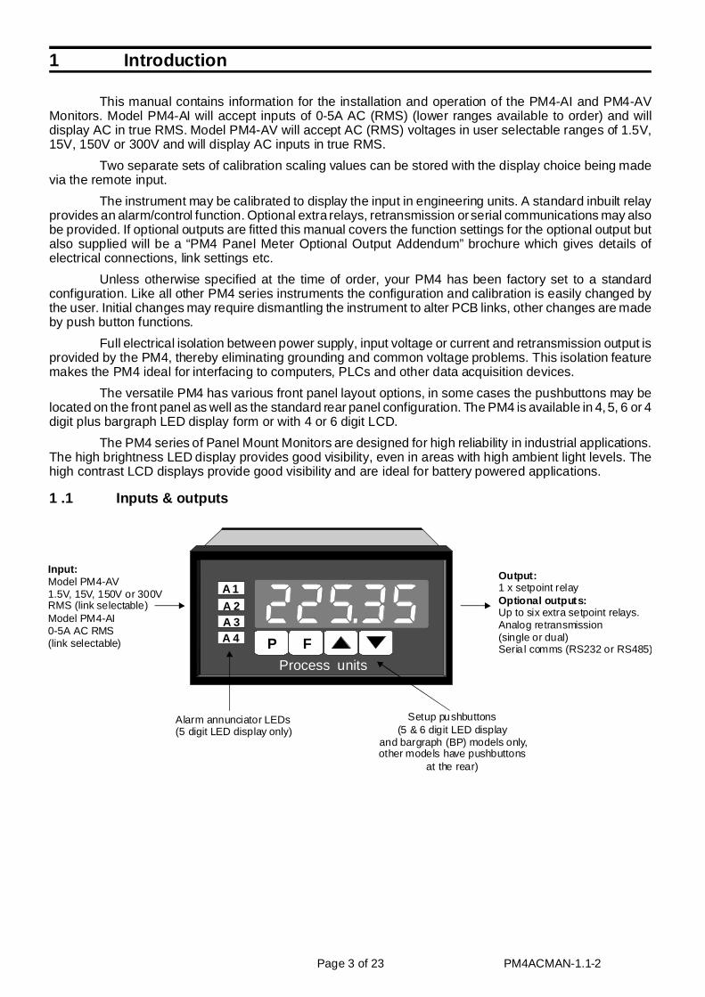
This manual contains information for the installation and operation of the PM4-AI and PM4-AVMonitors. Model PM4-AI will accept inputs of 0-5A AC (RMS) (lower ranges available to order) and willdisplay AC in true RMS. Model PM4-AV will accept AC (RMS) voltages in user selectable ranges of 1.5V,15V, 150V or 300V and will display AC inputs in true RMS.
Two separate sets of calibration scaling values can be stored with the display choice being madevia the remote input.
The instrument may be calibrated to display the input in engineering units. A standard inbuilt relayprovides an alarm/control function. Optional extra relays, retransmission or serial communications may alsobe provided. If optional outputs are fitted this manual covers the function settings for the optional output butalso supplied will be a “PM4 Panel Meter Optional Output Addendum” brochure which gives details ofelectrical connections, link settings etc.
Unless otherwise specified at the time of order, your PM4 has been factory set to a standardconfiguration. Like all other PM4 series instruments the configuration and calibration is easily changed bythe user. Initial changes may require dismantling the instrument to alter PCB links, other changes are madeby push button functions.
Full electrical isolation between power supply, input voltage or current and retransmission output isprovided by the PM4, thereby eliminating grounding and common voltage problems. This isolation featuremakes the PM4 ideal for interfacing to computers, PLCs and other data acquisition devices.
The versatile PM4 has various front panel layout options, in some cases the pushbuttons may belocated on the front panel as well as the standard rear panel configuration. The PM4 is available in 4, 5, 6 or 4digit plus bargraph LED display form or with 4 or 6 digit LCD.
The PM4 series of Panel Mount Monitors are designed for high reliability in industrial applications.The high brightness LED display provides good visibility, even in areas with high ambient light levels. Thehigh contrast LCD displays provide good visibility and are ideal for battery powered applications.
1 .1 In puts & out puts
Page 3 of 23 PM4ACMAN-1.1-2
P F
A 1A 2A 3A 4
Process units
Alarm annunciator LEDs(5 digit LED display only)
Setup pushbuttons(5 & 6 digit LED display
and bargraph (BP) models only, other models have pushbuttons
at the rear)
Input:Model PM4-AV 1.5V, 15V, 150V or 300VRMS (link selectable)Model PM4-AI0-5A AC RMS(link selectable)
Output:
Optional outputs:1 x setpoint relay
Up to six extra setpoint relays.Analog retransmission(single or dual)Seria l comms (RS232 or RS485)
2 Me chan i cal In stal la tion
If a choice of mounting sites is available then choose a site as far away as possible from sources ofelectrical noise such as motors, generators, fluorescent lights, high voltage cables/bus bars etc. An IP65access cover which may be installed on the panel and surrounds is available as an option to be used whenmounting the instrument in damp/dusty positions. A wall mount case is available, as an option, for situationsin which panel mounting is either not available or not appropriate. A portable carry case is also available, asan option, for panel mount instruments.
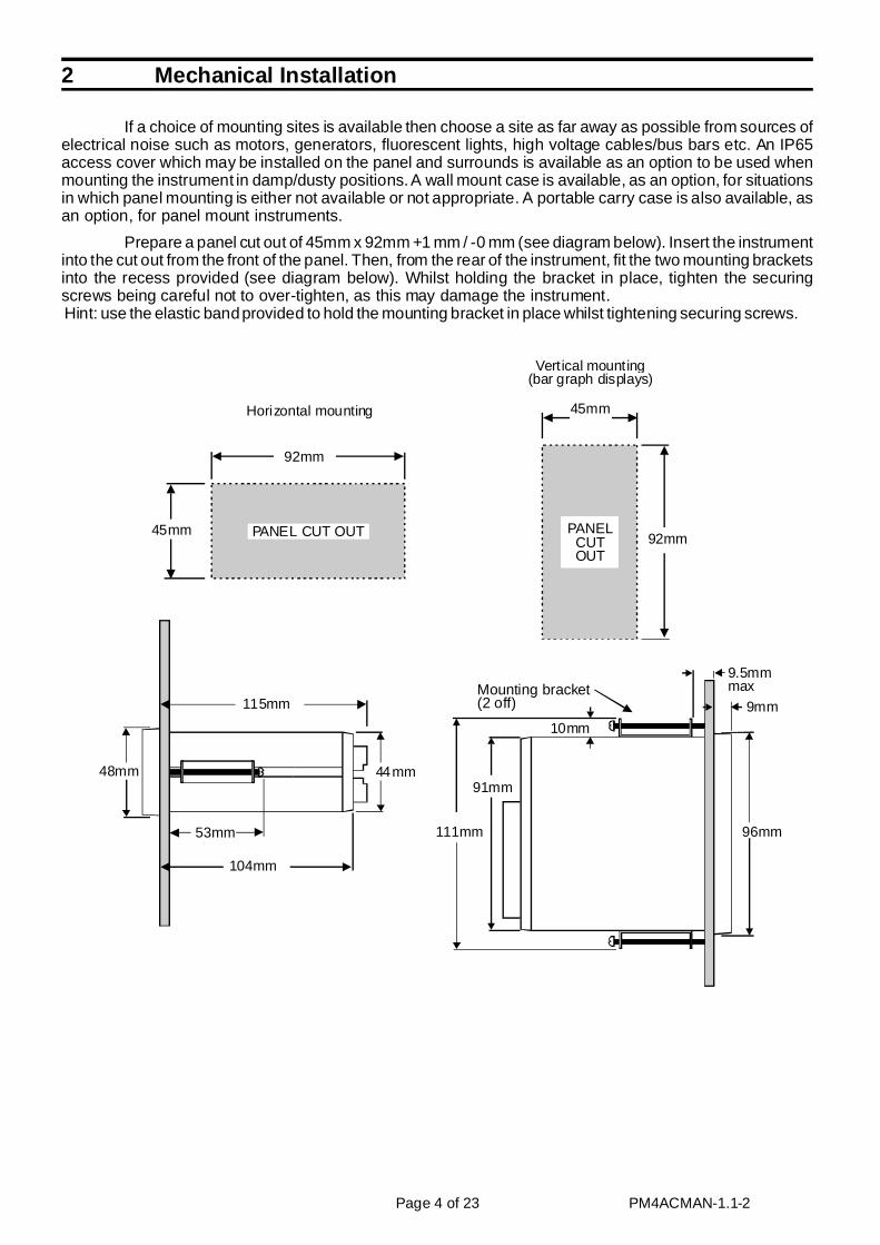
Prepare a panel cut out of 45mm x 92mm +1 mm / -0 mm (see diagram below). Insert the instrumentinto the cut out from the front of the panel. Then, from the rear of the instrument, fit the two mounting bracketsinto the recess provided (see diagram below). Whilst holding the bracket in place, tighten the securingscrews being careful not to over-tighten, as this may damage the instrument. Hint: use the elastic band provided to hold the mounting bracket in place whilst tightening securing screws.
Page 4 of 23 PM4ACMAN-1.1-2
92mm
45mm PANEL CUT OUT 92mm
45mm
PANELCUTOUT
115mm
104mm
53mm
44mm
96mm
9mm
9.5mmmax
48mm91mm
111mm
10mm
Mounting bracket(2 off)
Horizontal mounting
Vertical mounting(bar graph displays)
3 In put/Out put Con fig u ra tion
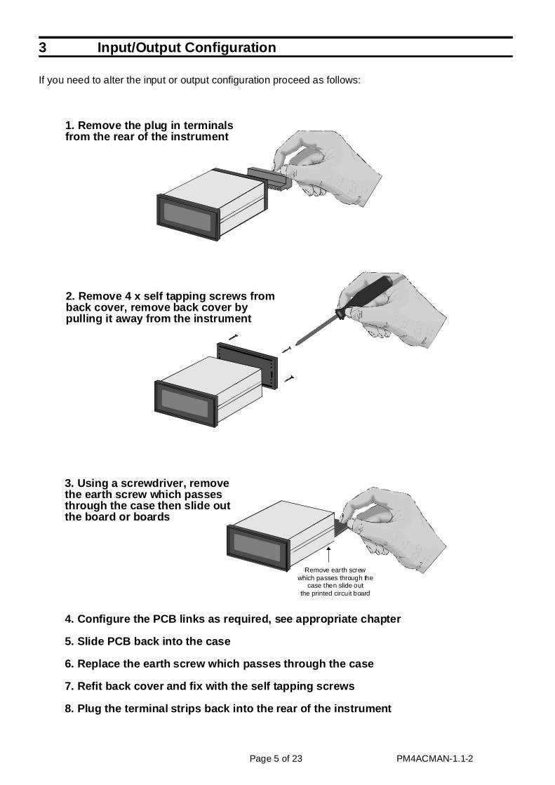
If you need to al ter the in put or out put con fig u ra tion pro ceed as fol lows:
Page 5 of 23 PM4ACMAN-1.1-2
Remove earth screw which passes through the
case then slide outthe printed circuit board
1. Re move the plug in ter mi nalsfrom the rear of the in stru ment
2. Re move 4 x self tap ping screws from back cover, re move back cover bypull ing it away from the in stru ment
3. Using a screw driver, re movethe earth screw which passesthrough the case then slide out the board or boards
4. Con fig ure the PCB links as re quired, see ap pro pri ate chap ter
5. Slide PCB back into the case
6. Re place the earth screw which passes through the case
7. Re fit back cover and fix with the self tap ping screws
8. Plug the ter mi nal strips back into the rear of the in stru ment
4 Elec tri cal In stal la tion
The PM4 Panel Meter is designed for continuous operation and no power switch is fitted to the unit.It is recommended that an external switch and fuse be provided to allow the unit to be removed for servicing.
The plug in, screw type, terminal blocks allow for wires of up to 2.5mm2 to be fitted. Connect thewires to the appropriate terminals as indicated below. Refer to connection details provided in this chapter toconfirm proper selection of voltage, polarity and input type before applying power to the instrument. Whenpower is applied to the instrument will cycle through a display sequence indicating the software version andother status information, this indicates that the instrument is functioning. Acknowledgement of correctoperation may be obtained by applying an appropriate input to the instrument and observing the reading.The use of screened cable is recommended for signal inputs.
See the “PM4 Panel Meter Optional Output Addendum” booklet supplied when of optional outputsare fitted.
Page 6 of 23 PM4ACMAN-1.1-2
1 MAINS EARTH2 240VAC NEU TRAL3 240VAC AC TIVE
5 RE LAY 1 COM6 RE LAY 1 N/O7 EXT IN8 GROUND9 IN PUT10 IN PUT GND PM4-AI-240-4E SE RIAL No:
SETUPPUSHBUTTONS
A B HC D E F J K
1 2 3 4 5 6 7 8 9 10
MAINS EARTH
AC ACTIVE
AC NEUTRALN/ORELAY 1
N/O
EXT-IN GNDINPUT
(DC+)
(DC-)
ACV MEASURE GROUND
ACV MEASURE ACTIVE
(ACI IN)
(ACI IN)
^v
Instrument Rear Panel
Instrument Data Label (example)

4 .1 Con nec tion ex am ples1. PM4-AI AC amps input
2.PM4-AV AC volts input
3. Remote input
Page 7 of 23 PM4ACMAN-1.1-2
ACV Measure ground
ACV Measure active
1 2 3 4 5 6 7 8 9 10
AC Amps
AC Amps
1 2 3 4 5 6 7 8 9 10
1 2 3 4 5 6 7 8 9 10
Momentary orlatching actionswitch
4 .2 Se lecting the in put rangeDismantle the instrument as described in Chapter 3, “Input/output configuration”. Insert the links
into the appropriate location on the pin header to suit the range required. The DC link allows DCmeasurement of an AC signal in which a DC component in the signal it to be taken into account in themeasurement. With the DC link in any DC component value in the AC waveform will be added to the RMSvalue of the waveform and displayed i.e. Display = DC value + RMS value.
Page 8 of 23 PM4ACMAN-1.1-2
INPUT BOARD
1.5V RMS range selected(PM4-AV only)
15V RMS range selected(PM4-AV only)
150V RMS range selected(PM4-AV only)
300V RMS range selected(PM4-AV only)
DC selected - al lows the DC component of any AC waveform to be added to the RMS value. If this link is out then only the AC component will be measured. This l ink can be usedon AC Volts or AC Amps inputs.
5 Ex pla na tion of Func tions
The PM4 setup and calibration functions are configured through a push button sequence. Twolevels of access are provided for setting up and calibrating:-
FUNC mode (simple push button sequence) allowsaccess to commonly set up functions such as alarmsetpoints.
CAL mode (power up sequence plus push buttonsequence) allows access to all functions including calibration parameters.
The three push buttons located at the rear of theinstrument (also at the front on some display options) areused to alter settings. Once CAL or FUNC mode has beenentered you can step through the functions, by pressing andreleasing the F push button, until the required function isreached. Changes to functions are made by pressing the ^or v push button (in some cases both simultaneously) whenthe required function is reached.
Page 9 of 23 PM4ACMAN-1.1-2
Process Units
Front view of instrument
SETUP PUSHBUTTONS
SETUPPUSH BUTTONS
Rear view of instrument
1 2 3 4 5 6 7 8 9 10 11
SETUPPU SH BUTTONS
F
F
^
^
v
v
Entering ModeCAL Entering ModeFUNC
1. Remove power fromthe instrument. Hold in the
button and reapply power.The display will briefly indicate
as part of the"wake up messages" whenthe message is seen
you can release the button. Move to step 2 below.
2. When the "wake up"messages have fin ished
and the display has settleddown to its normal reading
press, then release the button.
Move to step 3 below.
1. When the "wake up"messages have finished
and the display has settleddown to its normal reading
press, then release the button.
3. Within 2 seconds of releasing the button
press, then release the and buttons
together. The display willnow indicate followed
by the first function.
2. Within 2 seconds of releasing the button
press, then release the and buttons
together. The display willnow indicate followed
by the first function.
^^^^
FUNCFUNC
FF
F
F F
CAL
CAL
Note: If step 1 above has been completed then theinstrument will remain in this mode state until
power is removed. i.e. there is no need to repeat step 1when accessing function unless power has been removed.
CAL
No special power up procedureis required to enter mode.FUNC
The alarm and brightness functions below are accessible via FUNC mode.
Note that “x” in the alarm functions is used to indicate any alarm number e.g. if 3 setpoint alarm relays arefitted then A1Lo, A2Lo and A3Lo will all seen as functions on the display.
The PM4 has an easy alarm access facility which allows access to the alarm setpoints simply bypressing the F button at the front or rear of the instrument. The first setpoint will then appear and changes tothis setpoint may be made to this setpoint via the or v buttons. Press the F button to accept any changesor to move on to the next setpoint.
The instrument must be set in the manner described below to allow the easy access facility to work:
1. The R.INP function must be set to SP.AC or the ACCS function must be set to EASY.
2. At least one alarm must have a setpoint, nothing will happen if all the alarm setpoints are set to OFF.
3. The SP.AC function must be set to allow access to the relays required e.g. if set to A1-2 then theeasy access will work only with alarm relays 1 and 2 even if more relays are fitted.
4. The instrument must be in normal measure mode i.e. if the instrument is powered up so that it is inCAL mode then the easy access will not function. If in doubt then remove power from the instrument,wait for a few seconds then apply power again.
5. If the easy access facility is used then the only way to view or alter any other function settings is topower up via CAL mode i.e. there is no entry to FUNC mode unless the instrument is powered up in CAL
mode.
AxLo (alarm low setpoint)
Displays and sets the low setpoint value for the designated alarm relay. The low alarm setpoint maybe disabled by pressing the ^ and v pushbuttons simultaneously. When the alarm is disabled the displaywill indicate OFF. Use ^ or v to adjust the setpoint value if required. The alarm will activate when thedisplayed value is lower than the setpoint value. Each relay may be configured with both a low and highsetpoint if required, if so the relay will be activated when the display reading moves outside the band setbetween low and high setpoints.
AxHi (alarm high setpoint)
Displays and sets the high setpoint value for the designated alarm relay. The high alarm setpointmay be disabled by pressing the ^ and v pushbuttons simultaneously. When the alarm is disabled thedisplay will indicate OFF. Use or v to adjust the setpoint value if required. The alarm will activate whenthe displayed value is higher than the setpoint value. Each relay may be configured with both a low and highsetpoint if required, if so the relay will be activated when the display reading moves outside the band setbetween low and high setpoints.
AxHY (alarm hysteresis [deadband])
Displays and sets the alarm hysteresis limit and is common for both high and lowsetpoint values. The hysteresis value may beused to prevent too frequent operation of thesetpoint relay when the measured value staysclose to the setpoint. Without a hysteresissetting (AxHY set to zero) the alarm will activate when the display value goes above the alarmsetpoint (for high alarm) and will reset when thedisplay value falls below the setpoint, this canresult in repeated on/off switching of the relay at around the setpoint value. The hysteresissetting operates as follows:
In the high alarm mode, once the alarm is activated the input must fall below the setpoint valueminus the hysteresis value to reset the alarm.
e.g. if A1Hi is set to 50.0 and A1Hy is set to 3.0 then the setpoint output relay will activate oncethe display value goes above 50.0 and will reset when the display value goes below 47.0 (50.0 minus 3.0).
In the low alarm mode, once the alarm is activated the input must rise above the setpoint value plusthe hysteresis value to reset the alarm.
e.g. if A1Lo is set to 20.0 and A1Hy is set to 10.0 then the alarm output relay will activate whenthe display value falls below 20.0 and will reset when the display value goes above 30.0 (20.0 plus 10.0).
Page 10 of 23 PM4ACMAN-1.1-2
Display Value
Time
A Hix
A Hi
A HY
x
xminus Relay
activatesat this value
or above Relayresets
below thisvalue
A HYx value
Alarm high operation with hysteresis
The hysteresis units are expressed in displayed engineering units.
Axtt (alarm trip time)
Displays and sets the alarm trip timeand is common for both alarm high and lowsetpoint values. The trip time is the delay timebefore the alarm relay will activate, or trip,when an alarm condition is present. The alarm condition must be present continuously for the trip time periodbefore the alarm will trip. This function is useful for preventing an alarm trip due to short non critical deviations from setpoint. The trip time is selectable over 0 to 60 seconds.
Axrt (alarm reset time)
Displays and sets the alarm relay reset time. With the alarm condition is removed the alarm relay will stay in its alarm condition for the time selected as the reset time. The reset time is selectable over 0 to 60
seconds.
Axn.o or Axn.c (alarm x normally open or normally closed)
Displays and sets the setpoint alarm relay action to normally open (de-energised) or normallyclosed (energised), when no alarm condition is present. A normally closed alarm is often used to provide apower failure alarm indication.
Ax.SP, Ax.t1, Ax.t2 etc. (relay operation independent setpoint or trailing setpoint)
Each alarm may be programmed to operate with an independent setpoint setting or may be linked(or trailing) to operate at a fixed difference to another relay setpoint. The operation is as follows:
Alarm 1 (AI) is always independent. Alarm 2 (A2) may be independent or may be linked to Alarm 1.Alarm 3 (A3) may be independent or may be linked to Alarm 1 or Alarm 2. Alarm 4 (A4) may beindependent or may be linked to Alarm 1, Alarm 2 or Alarm 3. The operation of each alarm is selectablewithin the Function Setup Mode by selecting, for example, (Alarm 4) A4.SP = Alarm 4 normal setpoint or A4.t1 = Alarm 4 trailing Alarm 1 or A4.t2 = Alarm 4 trailing Alarm 2 or A4.t3 = Alarm 4 trailing Alarm3. For trailing set points the setpoint value is entered as the difference from the setpoint being trailed. Ifthe trailing setpoint is to operate ahead of the prime setpoint then the value is entered as a positivenumber and if operating behind the prime setpoint then the value is entered as a negative number. Forexample, with Alarm 2 set to trail alarm 1, if A1Hi is set to 1000 and A2Hi is set to 50 then Alarm 1 willactivate at 1000 and alarm 2 will activate at 1050 (i.e. 1000 + 50). If Alarm 2 had been set at -50 thenalarm 2 would activate at 950 (i.e. 1000 - 50). See the trailing alarm table which follows.
Trailing Alarm Ta ble Showing Pos si ble Alarm As sign ments
A2 A3 A4 A5 A6 A7
A1 A2.t1 A3.t1 a4.t1 a5.t1 A6.t1 a7.t1
A2 A3.t2 A4.t2 a5.t2 a6.t2 a7.t2
A3 a4.t3 a5.t3 a6.t3 a7.t3
A4 a5.t4 a6.t4 a7.t4
A5 a6.t5 a7.t5
A6 a7.t6
Page 11 of 23 PM4ACMAN-1.1-2
Display Value
Time
A LoxA HYx value
A Lo
A HY
xplus
x
Relayactiva tes
at this value or below
Relayresets
above thisvalue
Alarm low operation with hysteresis
Alarm relaycontacts areopen if no alarmcondition present
Alarm relaycon tacts areclosed if no alarmcondition present
Alarm relaycontacts closeduring ala rmcondition
Alarm relaycontacts openduring alarmcondition
Alarm normally open Alarm normally closed

brgt (display brightness)
Displays and sets the digital display brightness. The display brightness is selectable from 1 to 15,
where 1 = lowest intensity and 15 = highest intensity. This function is useful for improving the displayreadability in dark areas or to reduce the power consumption of the instrument.
dULL (remote display brightness)
Displays and sets the level for remote input brightness switching, see R.INP function. When theremote input is set to dULL the remote input can be used to switch between the display brightness level setby the brGt function and the display brightness set by the dULL function. The display brightness isselectable from 0 to 15, where 0 = lowest intensity and 15 = highest intensity. This function is useful inreducing glare when the display needs to be viewed in both light and dark ambient light levels.
The functions which follow are accessible via CAL mode only.
bAr_ (bar graph display low value) - seen only in bargraph display instruments.
Displays and sets the bar graph low value i.e. the value on the 7segment display at which the bargraph will start to rise. This may beindependently set anywhere within the display range of the instrument.
Note: The bAr~ and bAr_ settings are referenced from the 7segment display readings, not the bargraph scale values. The bargraphscale may scaled differently to the 7 segment display, as shown on the rightwhere bargraph scale is 0 to 100 yet the display is showing 675.3. In thisexample the bargraph scale may be indicating percentage of full rangewhilst the 7 segment display is indicating actual process units.
bAr~ (bargraph display high value) - seen only in bargraph display instruments.
Displays and sets the bar graph high value i.e. the value on the 7 segment display at which thebargraph will reach its maximum indication (all LED’s illuminated). May be independently set anywherewithin the display range of the instrument.
bAr tYPE (bar graph display operation mode) - seen only in bargraph display instruments.
Allows selection of bargraph operation mode choices are:
bAr - conventional solid bargraph display i.e. all LED’s illuminated when at full scale.
When scaling the display use the bAr_ and bAr~ functions e.g. bAr_ = 0 and bAr~ = 100 will give abargraph with no segments lit at a 7 segment display reading of 0 and all segments lit with a 7 segmentdisplay reading of 100.
S.dot - single dot display. A single segment will be lit to indicate the input readings position on thescale.
When scaling the display use the bAr_ and bAr~ functions e.g. bAr_ = 0 and bAr~ = 100 will give abargraph with the bottom segment lit at a 7 segment display reading of 0 and the top segment lit with a 7segment display reading of 100.
Note: this could also be set up as a centre zero single dot display by entering a negative value andpositive value. e.g. bAr_ = -100, bAr~ = 100.
d.dot - double dot display. Two segments will be lit to indicate the input reading position on the scale.The reading should be taken from the middle of the two segments.
When scaling the display use the bAr_ and bAr~ functions e.g. bAr_ = 0 and bAr~ = 100 will give abargraph with the bottom two segments lit at a 7 segment display reading of 0 and the top two segmentslit with a 7 segment display reading of 100.
Note: this could also be set up as a centre zero single dot display by entering a negative value andpositive value. e.g. bAr_ = -100, bAr~ = 100.
C.bAr - centre bar display. The display will be a solid bargraph but will have its zero point in the middleof the display. If the seven segment display value is positive the bargraph will rise. If the seven segmentdisplay value is negative then the bargraph will fall.
When scaling the display use the bAr_ and bAr~ functions e.g. bAr_ = 0 and bAr~ = 100 will give abargraph with all the bottom half segments lit at a 7 segment display reading of -100 and all the topsegments lit with a 7 segment display reading of 100.
Page 12 of 23 PM4ACMAN-1.1-2
F
1
2
3
4
P
100
75
50
25
0
6 7 % 3
%
7 SegmentDisplay
BargraphScale
bAr ~
b Ar_
rEC_ (recorder/retransmission output low value) - seen only when analog retransmission option fitted.Refer to the separate “PM4 Panel Meter Optional Output Addendum” booklet supplied when this option isfitted.
Displays and sets the analog retransmission (4-20mA, 0-1V or 0-10V, link selectable) output lowvalue (4mA or 0V) in displayed engineering units. e.g. if it is required to retransmit 4mA when the displayindicates 0 then select 0 in this function via the ^ or v button.
rEC~ (recorder/retransmission output high value) - seen only when analog retransmission option fitted. Refer to the separate “PM4 Panel Meter Optional Output Addendum” booklet supplied when this option isfitted.
Displays and sets the analog retransmission (4-20mA, 0-1V or 0-10V, link selectable) output highvalue (20mA, 1V or 10V) in displayed engineering units. e.g. if it is required to retransmit 20mA when thedisplay indicates 500 then select 500 in this function via the ^ or v button.
drnd (display rounding)
Displays and sets the display rounding value. This value may be set to 0 - 5000 displayed units.Display rounding is useful for reducing the instrument resolution without loss of accuracy, in applicationswhere it is undesirable to display to a fine tolerance. (example if set to 10 the display indication will change in multiples of 10 only).
dCPt (decimal point selection)
Displays and sets the decimal point. By pressing the or v pushbuttons the decimal point position may be set. The display will indicate as follows: 0 (no decimal point), 0.1 (1 decimal place), 0.02 (2 decimalplaces), 0.003 (3 decimal places) and 0.0004 for display with more than 4 digits.
5 .1 Cal i bra tion func tionsCAL1 (first scaling point for 2 point scaling method)
CAL1 and CAL2 are used together to scale the instruments display, values for both must be setwhen using this scaling method. Ensure that the required decimal point position is selected prior tocalibration.
The CAL1 function sets the first calibration point for live input calibration . When using this methoda signal input must be present at the input terminals. Note: CAL1 and CAL2 can be set independently.
The procedure for entering the first scaling point is:
a. Ensure that an input signal is present at the input terminals, this will usually be at the low end of thesignal range e.g. 0 Amps.
b. At the CAL1 function press and v simultaneously then release them. The display will indicate thelive input value. Do not be concerned at this stage if the live input display value is not what is required. Itis important that the live input value seen is a steady value, if not then the input needs to be investigatedbefore proceeding with the scaling.
c. Press, then release the F button. The display will indicate SCL1 followed by a value. Use the orv button to change this value to the required display value at this input. e.g. if 0A was input and therequired display at 0A was 0.0 then ensure 0.0 is selected at SCL1. Press the F button to acceptchanges or the P button to abort the scaling.
CAL2 (second scaling point for 2 point scaling method)
The second point scaling is performed in exactly the same manner as CAL1 except that SCL2 willbe seen instead of SCL1. It is essential that the live input is different in value to the CAL1 input e.g. for a 0 to5A input use 5A as the CAL2 live input. Note; it is not essential that 0 and 5A are used as the live inputs for a 0 to 5A scaling but there must be at least a 10% of full scale difference between the CAL1 and CAL2 inputs, ifthis is not the case then a SPAN Err message will be seen and the calibration point will not be accepted.
Page 13 of 23 PM4ACMAN-1.1-2

Page 14 of 23 PM4ACMAN-1.1-2
Input Input CAL2
CA L2
CAL1
SC L1
CA L1
SCL2
Setting CAL1 Setting CAL2
Example - Scaling AC Amps using two live inputs
Enter via mode,see page 9
CAL
Place at the input a low level signal for which the required
scaling value is known e.g. 0A
Go to the functionand press and
simultaneously a "live"display will now be seen
CAL1
^ v
If the "live" display is stablepress the button. The
message will be seenF
S CL1
If the "live" display is stablepress the button. The
message will be seenF
SCL2
Use the or button to enter the required scale
value for the input then press to accept the new scaling value
^ v
F
Use the or button to enter the required scale value for the second input then pressand release to accept the
new scaling value
^ v
F
Press and release until the message is seen and the display
returns to normal measurement
FUNC E nd
F
The message will be seen.Increase the input signal then
press and simultaneously.Ideally the second input should be
as close to 100% of range as possible e.g. 5A. A "live"display will now be seen
CAL2
^ v
Note: If the "live" display at any scaling point is not stable then check the input signal for stability.

CAL OFSt (calibration offset)
The calibration offset is a single point adjustment which can be used to alter the calibration scalingvalues across the entire measuring range without affecting the calibration slope. This method can be usedinstead of performing a two point calibration when a constant measurement error is found to exist across theentire range. To perform a calibration offset press the ^ and v buttons simultaneously at the CAL OFSt
function. A "live" reading from the input will be seen, make a note of this reading. Press the F button, themessage SCLE will now be seen followed by the last scale value in memory. Use the or v button to adjust the scale value to the required display value for that input. For example if the "live" input reading was 50 andthe required display value for this input was 70 then adjust the SCLE value to 70.
UCAL (uncalibration)
Used to set the instrument back to the factory calibration values. This function should only be usedwhen calibration problems exist, and it is necessary to clear the calibration memory. To clear the memorypress the and v buttons simultaneously at the functions. The message CAL CLr will be seen to indicatethat the memory has cleared.
FREQ (frequency display enable)
If this function is set to on the display can be toggled to the frequency display via the ^ or vbutton, the message FREQ will be shown prior to the frequency reading. If this function is set to OFF nofrequency reading will be available.
FREQ dCPt (decimal point position for frequency display)
Displays and sets the decimal point position for the frequency display, settings available are 0 (nodecimal point), 0.1 (one decimal point place), 0.02 (two decimal point places etc. The maximum number ofdecimal places available depends on the number of display digits.
FREQ INPt (frequency input factor)
The frequency input factor is used with the frequency scale factor described below to allow thefrequency display to be scaled as required. This factor must be a whole number.
FREQ SCLE (frequency scale factor)
The frequency scale factor is used with the frequency input factor to allow the frequency display tobe scaled. The frequency scale factor has the same number of decimal points as the FREQ dCPt function.The two factors work together as follows:
Frequency displayed = FREQ SCLE x actual frequency of the input voltage or current (Hz) FREQ INPt
For example to display the actual input frequency set both the FREQ INPt and FREQ SCLE to 1. If at an input of 200HZ the display is required to show a frequency of 300Hz then set the FREQ INPt to 2and the FREQ SCLE to 3.
FREQ FLtr (digital filter for the frequency display)
Displays and sets the digital filter value for the frequency display. Digital filtering is used for reducing susceptibility to short term interference. The digital filter range is selectable from 0 to 8, where 0 = none and 8= most filtering. A typical value for the digital filter would be 3. Use or v to alter if required. Note that athigher filter values the display update time will increase.
dFLt dISP (default display)
The default display function allows the display to default to either the voltage or current reading(INPt) or the frequency display (FREQ). The or v button can be used to toggle between the default andalternate display, the P button and remote input can also be programmed to allow toggling between thedefault and alternate display. The instrument will alway show the default display when switched on and when toggled to the alternate display a message (FREQ or INPt) will flash once every 8 seconds to indicate thatthe display being viewed is the alternate display.
P.but (P button function)
Applicable only in models with front panel P buttons.
The P button may be set to operate some of the remote input functions, see R.INP below for adescription of these functions. The P button is located at the front of 5 or 6 digit LED models. With somefunctions, to prevent accidental operation, the P button must be held pressed for 2-3 seconds before thefunction will operate. If both the remote input and P button function are operated simultaneously the Pbutton will override the remote input. The functions below are as described in the R.INP function below.
Page 15 of 23 PM4ACMAN-1.1-2

Functions available are: NONE, Hi, Lo , HiLo, ZERO, P.SEt or dISP
R.INP (remote input function)
Pins 7 and 8 at the rear of the instrument are the remote input pins. When these pins are shortcircuited, via a pushbutton or keyswitch the instrument will perform the selected remote input function. Amessage will flash to indicate which function has been selected when the remote input pins are shortcircuited. The remote input functions are as follows:
NONE - no remote function required.
P.HLd - peak hold. The display will show the peak value only whilst the remote input pins are shortcircuited.
d.HLd - display hold. The display value will be held whilst the remote input pins are short circuited.
Hi - peak memory. The peak value stored in memory will be displayed if the remote input pins are shortcircuited, if the short circuit is momentary then the display will return to normal measurement after 20seconds. If the short circuit is held for 1 to 2 seconds or the power is removed from the instrument thenthe memory will be reset.
Lo - valley memory. The minimum value stored in memory will be displayed. Otherwise operates in thesame manner as the Hi function.
HiLo - toggle between Hi and Lo displays. This function allows the remote input to be used to togglebetween peak and valley memory displays. The first operation of the remote input will cause the peakmemory value to be displayed, the next operation will give a valley memory display. P Hi or P Lo willflash before each display to give an indication of display type.
ZERO - display zero. Zeroes the display. The input at the time of the zero will be the new zero level. Thezero will be retained at this level even is power is removed to the instrument.
SP.Ac - setpoint access only. This blocks access to any functions except the alarm setpoint functionsunless the remote input pins are short circuited or entry is made via CAL mode.
No.Ac - no access. This blocks access to all functions unless the remote input pins are short circuited orentry is made via CAL mode.
CAL.S - calibration select. The remote input can be used to select between calibration scaling values.Two sets of calibration values can be entered in the PM4, one set with the remote input open circuit andanother set with the remote input short circuit to ground. The remote input can then be used to switchbetween one set and the other. For example: With the remote input open circuit a 0-50V input can bescaled (using CAL1 & CAL2) to read 0 to 100 over the 0-50V range. With the remote input short circuitto ground the scaling can be repeated using figures of 0 to 500 for the 0-50V range. The remote inputcan be used to switch between ranges. In this example the first scaling could represent a % figure andthe second scaling could represent the actual process units. Note: Alarm settings will not change whenchanging between calibrations scales. i.e. Only one set of alarm functions can be made and the alarmrelay will operate from those set values no matter which calibration scale is being viewed at the time.
P.SEt - preset value. Not applicable to this model.
dISP - display toggle. The remote input can be used to toggle between the default and alternate display as set by the dISP function described earlier. When the remote input contact is open the default display will be seen. When the remote input contact is open the default display will be viewed. When the remoteinput contact is closed the alternate display will be seen and a message (INPt or FREQ) will flash onceevery 8 seconds to warn that the alternate display is being viewed.
dULL - display brightness control. The remote input can be used to change the display brightness.When this mode is selected the display brightness can be switched, via the remote input, between thebrightness level set at the brgt function and the brightness level set at the dULL function.
ACCS (access mode)
The access mode function ACCS has four possible settings namely OFF, EASY, NONE and ALL.If set to OFF the mode function has no effect on alarm relay operation. If set to EASY the easy alarm accessmode will be activated, see details at the beginning of this chapter preceding the A1Lo function. If set toNONE there will be no access to any functions via FUNC mode, entry via CAL mode must be made to gainaccess to alarm and calibration functions. If set to ALL then access to all functions, including calibrationfunctions, can be gained via FUNC mode.
Page 16 of 23 PM4ACMAN-1.1-2
SPAC (setpoint access) - seen only if more than 1 relay fitted.
Sets the access to the alarm relay set points. The following choices are available:
A1 - Allows setpoint access to alarm 1 only.
A1-2 - Allows access to alarms 1 and 2 only.
A1-3 allows access to alarms 1,2 and 3 etc. up to the maximum number of relays fitted.
The remote input function (R.INP) must be set to SP.AC for this function to operate . Note: Only thesetpoints which have been given a value will be accessible e.g. if A1Hi is set to OFF then there will be noaccess to the A1Hi function when SPAC is used.
5 .2 Alarm, bargraph and re trans mis sion op er a tion modesThe following describes the output modes for alarm, bargraph, analog, serial and digital retransmission.The serial output (RS232 or RS485) can alternatively be controlled via polling commands.Retransmission and extra alarm relays are optional outputs. The following commands only apply if theoption is fitted to the instrument. Refer to the separate “PM4 Panel Meter Optional Output Addendum”booklet supplied when optional outputs are fitted.
A1, A2 etc. (Alarm relay operation mode for relays 1, 2 etc.)
The following choices are available for alarm operation mode:
LiuE - live input mode. The alarm relay operation will always follow the electrical input at that timeirrespective of the 7 segment display value. e.g. assume the remote input is set to ZERO and A1Hi isset to 100. If the instrument is zeroed at a display reading of 30 then the alarm will now activate at adisplay reading of 70.
FREQ - frequency mode. The alarm relay operation will follow the frequency rather than the voltage orcurrent.
P.HLd - peak hold mode. If the peak hold mode is used and the remote input is set to peak hold thenonce the peak display goes above any alarm high setpoint the alarm relay will activate and will notde-activate until the peak hold is released and the display value falls below the setpoint value.
d.HLd - display hold mode. If the display hold mode is used and the remote input is set to display holdthen the alarm relay will be held in its present state (activated or de-activated) until the display hold isreleased and the display is free to change.
Hi - peak (max.) memory mode. If the peak memory mode is used and the remote input is set to peakmemory then the alarm will be activated if the peak memory value is above the high setpoint value. Thealarm will not de-activate until the memory is reset.
Lo - valley (min.) memory mode. If the valley memory mode is used and the remote input is set to valleymemory then the alarm relay will be activated if the valley memory value is below the low setpoint value.The alarm will not de-activate until the memory is reset.
dISP - display mode. If the live display mode is used then the alarms will operate purely on the displayvalue at the time i.e. if the display is showing above high setpoint or below the low setpoint value then the alarm relay will activate. For example if the remote input were set to peak memory and A1 were set tolive display mode then, unless the display is actually showing the peak memory value (i.e. the remoteinput has just been activated), the alarm relay is free to operate from the changing display value i.e. thememory does not have to be reset to clear an alarm condition.
bAR (bargraph operation mode) - applicable only to bargraph displays.
The following choices are available for bargraph operation mode:
LiuE - live input mode. The bargraph will respond to the electrical input only and will not necessarilyfollow the 7 segment display value. For example if the remote input is set for peak hold operation thenwhen the remote input is closed the 7 segment display will only show the peak value but the bargraph will be free to move up and down to follow the electrical input.
FREQ - frequency mode. The bargraph will follow the frequency rather than the voltage or current.
P.HLd - peak hold mode. The bargraph (and 7 segment display) will indicate the peak value only whilstthe peak value function is operated via a contact closure on the remote input i.e. the bargraph & 7segment display can rise but not fall whilst the remote input switch is closed. When the remote inputswitch is opened the bargraph value will remain fixed i.e. it will not rise or fall, although the 7 segmentdisplay value will be free to alter. This peak bargraph reading can be cleared by closing the remote input
Page 17 of 23 PM4ACMAN-1.1-2
switch for another operation or by removing power from the instrument. Note: In this mode the bargraphwill show a zero reading until the remote input is operated for the first time after switch on.
d.HLd - display hold mode. The bargraph (and 7 segment display) value will be held whilst the remoteinput display hold switch is closed. When the switch is opened the bargraph value will remain fixed at theheld value although the 7 segment display value will be free to alter. The held bargraph reading can becleared by closing the remote input switch for another operation or by removing power from theinstrument. Note: In this mode the bargraph will show a zero reading until the remote input is operatedfor the first time after switch on.
Hi - peak (max.) memory mode. With the peak remote input switch open the bargraph will indicate thepeak value in memory i.e. the bargraph can rise but not fall. The bargraph can be reset by clearing thememory. The memory may be cleared either by closing the remote input switch for approximately 2seconds or by removing power to the instrument.
Lo - valley (min.) memory mode. With the valley remote input switch open the bargraph will indicate thevalley (min.) value in memory i.e. the bargraph can fall but not rise. The bargraph can be reset byclearing the memory. The memory may be cleared either by closing the remote input switch forapproximately 2 seconds or by removing power to the instrument.
dISP - display mode. The bargraph display will follow whatever value is on the 7 segment display. Forexample if the remote input is set to P.HLd then the 7 segment and bargraph will indicate the peakvalue.
REC (analog retransmission operation mode) and SERL (serial retransmission). Refer to the separate “PM4 Panel Meter Optional Output Addendum” booklet supplied when optional outputs are fitted.
The following choices are available for analog, digital or serial retransmission operation mode:
LiuE - live input mode. The retransmission will follow the electrical input and will not necessarily followthe 7 segment or bargraph display. For example if the remote input is set for peak hold operation thenwhen the remote input is closed the 7 segment display will only show the peak value but theretransmission will be free to change to follow the electrical input.
FREQ - frequency mode. The retransmission will follow the frequency rather than the voltage or current.
P.HLd - peak hold mode. The 7 segment display and retransmission value will indicate the peak valueonly whilst the peak value function is operated via a contact closure on the remote input i.e. the 7segment display and retransmission can rise but not fall whilst the remote input switch is closed. Whenthe remote input switch is opened the retransmission value will remain fixed i.e. it will not rise or fall,although the 7 segment display value will be free to alter. This peak retransmission output can becleared by closing the remote input switch for another operation or by removing power from theinstrument. Note: In this mode the retransmission will show a zero reading until the remote input isoperated for the first time after switch on.
d.HLd - display hold mode. The 7 segment display and retransmission value will be held whilst theremote input display hold switch is closed. When the switch is opened the retransmission value willremain fixed at the held value although the 7 segment display value will be free to alter. The heldretransmission output can be cleared by closing the remote input switch for another operation or byremoving power from the instrument. Note: In this mode the bargraph will show a zero reading until theremote input is operated for the first time after switch on.
Hi - peak (max.) memory mode. With the peak remote input switch open the retransmission will indicate the peak value in memory i.e. the retransmission output can rise but not fall. The retransmission outputcan be reset by clearing the memory. The memory may be cleared either by closing the remote inputswitch for approximately 2 seconds or by removing power to the instrument.
Lo - valley (min.) memory mode. With the valley remote input switch open the retransmission willindicate the valley (min.) value in memory i.e. the retransmission output can fall but not rise. Theretransmission output can be reset by clearing the memory. The memory may be cleared either byclosing the remote input switch for approximately 2 seconds or by removing power to the instrument.
dISP - display mode. The retransmission output will follow whatever value is on the 7 segment display.For example if the remote input is set to P.HLd then the 7 segment and retransmission output willindicate the peak value.
Page 18 of 23 PM4ACMAN-1.1-2

Lo dISP (low overrange limit value)
The display can be set to show an overrange message if the display value falls below the Lo dISP
setting. For example if Lo dISP is set to 50 then once the display reading falls below 50 the message-or- or the display value (see dISP function) will flash instead of the normal display units. This messagecan be used to alert operators to the presence of an input which is below the low limit. If this function is notrequired it should be set to OFF by pressing the ^and v buttons simultaneously at this function.
HIGH dISP (high overrange limit value)
The display can be set to show an overrange message if the display value rises above the HIGH
dISP setting. For example if HIGH dISP is set to 1000 then once the display reading rises above 1000
the message -or- or the display value (see dISP function) will flash instead of the normal display units.This message can be used to alert operators to the presence of an input which is above the high limit. If thisfunction is not required it should be set to OFF.
dISP (overrange warning mode)
The display overrange warning set by the Lo dISP and HIGH dISP functions can be set tocause the display value to flash or cause the message -or- to flash as an overrange warning. If set toFLSH the display value will flash when in an overrange condition, if set to -or- this message will flashwhen in an overrange condition.
5 .3 Se rial out put func tionsThe functions which follow are only seen if the serial output option is fitted. Refer to the separate
“PM4 Panel Meter Optional Output Addendum” booklet supplied when optional outputs are fitted.
bAud (set baud rate) - seen only with serial output option.
Select from 300, 600, 1200, 2400, 4800, 9600, 19.2 or 38.4.
Prty (set parity) - seen only with serial output option.
Select parity check to either NONE, EUEN or odd.
O.Put (set serial interface mode) - seen only with serial output option.
Select diSP, Cont, POLL or M.bus
Allows user to select the serial interface operation as follows:-
disP Sends image data from the display without conversion to ASCII.
Cont Sends ASCII form of display data every time display is updated.
POLL Controlled by computer or PLC as host. Host sends command via RS232/485 and instrumentresponds as required.M.bus Modbus RTU protocol.
Addr (set unit address for polled (POLL) mode (0 to 31)) - seen only with serial output option.
Allows several units to operate on the same RS485 interface reporting on different areas etc. Thehost computer or PLC may poll each unit in turn supplying the appropriate address.
The unit address ranges from 0 to 31 (DEC) but is offset by 32 (DEC) to avoid clashing with ASCIIspecial function characters (such as <STX> and <CR>). Therefore 32 (DEC) or 20 (HEX) is address 0, 42(DEC) or 2A (HEX) addresses unit 10.
SERL - (serial retransmission mode)
Applies only when O.Put function set to Cont. Refer to REC function on previous page forfunction description. The HiLo selection in this functions allows both the peak and valley memories to betransmitted. The peak value will be transmitted followed by a space then the valley value.
Returning to normal measure mode
When the calibration has been completed it is advisable to return the instrument to the normal mode (where calibration functions cannot be tampered with).To return to normal mode, turn off power to theinstrument, wait a few seconds and then restore power.
Page 19 of 23 PM4ACMAN-1.1-2

6 Func tion Ta ble
Ini tial dis play Mean ing of dis play Next dis play De faultSet ting
Re cordYour
Set tings
AxLo Alarm low set point value Set point value or OFF OFFSee fol low ing
ta ble
Ax Hi Alarm high set point value Set point value or OFF OFFSee fol low ing
ta ble
AxHy Alarm hys tere sis Hys tere sis value in meas uredunits
1See fol low ing
ta ble
Axtt Alarm trip timeNo of sec onds be fore re lay
trips 0See fol low ing
ta ble
Axrt Alarm re set time Re set time in sec onds 0See fol low ing
ta ble
Axn.o or Axn.c Alarm ac tion N/O or N/C Axn.o or Axn.c A1n.oSee fol low ing
ta ble
Ax.SP or Ax.tI Set point or trailing alarm Ax.SP or AxtI Ax.SPSee following
tablebrgt Dis play bright ness 1 to 15 15
dULLRe mote dis play bright ness
switch ing 0 to 15 1
Func tions be low are ac ces si ble only via CAL mode.bAr_ Bargraph low read ing Value in mem ory 0
bAr~ Bar graph high read ing Value in mem ory 1000
bAr tYPE Bar graph op era tion mode bAr, S.dot, d.dot or C.bAr bAr
rEC_ Re corder out put low limit Value in mem ory 0
rEC~ Re corder out put high limit Value in mem ory 1000
drndDis play rounding selects
reso lu tionValue in mem ory 1
dCPt Dis play deci mal point Deci mal point po si tion 0
CAL1 First live in put scal ing point Live read ing n/a
CAL2Sec ond live in put scal ing
point Live read ing n/a
CAL OFSt Offset to calibration Live Reading n/a
UCAL Un cali brate CAL CLr n/aFREQ Frequency display on or off on or OFF OFF
FREQ dCPtFrequency display decimal
point 0, 0.1, 0.002 etc. 0.1
FREQ INPtFrequency display input
scale value Value in memory 1
FREQ SCLEFrequency display scale
value Value in memory 1.0
FREQ FLtrFrequency display digital
filter setting0 to 8 2
dFLt dISPDefault display, current or
frequencyINPt or FREQ INPt
P.but P but ton func tionNONE, Hi, Lo, HiLo, ZERO,
P.SEt or dISPNONE
R.INP Re mote in put func tion
NONE, PHLd, dHLd, Hi, Lo,
HiLo, ZERO, SP.Ac, No.Ac,
CAL.S, P.SEt, dISP ordULL
NONE
ACCS Access mode OFF, EASY, NONE or ALL OFF
SPAC Set point ac cess A1, A1-2 etc. A1
A1 Alarm 1 op era tion modeLiuE, FREQ, P.HLD, d.HLd,
Hi, Lo or dISPLiuE
Page 20 of 23 PM4ACMAN-1.1-2
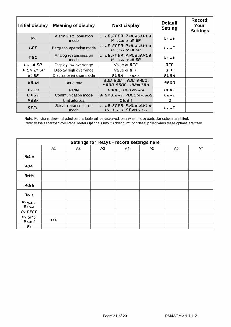
Ini tial dis play Mean ing of dis play Next dis play De faultSet ting
Re cordYour
Set tings
AxAlarm 2 etc. operation
modeLiuE, FREQ, P.HLD, d.HLd,
Hi, Lo or dISPLiuE
bAR Bargraph operation mode LiuE, FREQ, P.HLD, d.HLd,
Hi, Lo or dISPLiuE
RECAna log re trans mis sion
modeLiuE, FREQ, P.HLD, d.HLd,
Hi, Lo or dISPLiuE
Lo dISP Display low overrange Value or OFF OFF
HIGH dISP Display high overrange Value or OFF OFF
DISP Display overrange mode FLSH or -or- FLSH
bAUD Baud rate300, 600, 1200, 2400,
4800, 9600, 1(2 or 3*49600
Prty Par ity NONE, EUEN or odd NONE
O.Put Com mu ni ca tion mode diSP, Cont, POLL or m.bus Cont
Addr Unit ad dress 0 to 31 0
SERLSerial retransmission
modeLiuE, FREQ, P.HLD, d.HLd,
Hi, Lo, dISP or HiLoLiuE
Page 21 of 23 PM4ACMAN-1.1-2
Note: Functions shown shaded on this table will be displayed, only when those particular options are fitted.Refer to the separate “PM4 Panel Meter Optional Output Addendum” booklet supplied when these options are fitted.
Set tings for re lays - rec ord set tings hereA1 A2 A3 A4 A5 A6 A7
AxLo
AxHi
AxHY
Axtt
Axrt
Axn.o orAxn.c
Ax OPER
Ax.SP orAx.t1
n/a
Ax

7 Spec i fi ca tions
7 .1 Tech ni cal Spec i fi ca tionsIn put: AC cur rent (model PM4-AI)
AC volts (model PM4-AV)Dis play can also show in put fre quency (Hz)
Mea suring Range: True RMS 0 to 5A (PM4-AI), lower ranges avail able to or der or True RMS 1.5V, 15V, 150 or 300V link selectable (PM4-AV)
Max. crest fac tor: 5 for volt age & cur rent, up to 600V max.
Im ped ance: 20 milliohms (typ i cal, PM4-AI), 1MΩ (all ranges PM4-AV)
Iso la tion: 2kV peak for 30 sec onds, 250VAC RMS @ 50Hz con tin u ous
Ac cu racy: Volt age & cur rent dis play 0.3% of full scale typ i cal(over 5 to 100% of full scale, 30Hz to 10kHz, when fre quency used when mea sur ing is the same as fre quency used when cal i brat ing)Fre quency dis play 0.01% typ i cal(over 5 to 100% of full scale volt age & cur rent in put, 10 to 500Hz)
Fre quency up date time: 20mS or 1 cy cle, which ever is the lon gest (fil ter (FLtr) set at 0)
Sam ple Rate: 7 per sec (approx.)
Con ver sion Method: Dual Slope ADC
Mi cro pro ces sor: MC68HC11CMOS
Am bi ent Tem per a ture: LED -40 to 60oC, LCD -10 to 50oC
Hu mid ity: 5 to 95% non con dens ing
Dis play: LED Models 4 digit 20mm,5 digit 14.2mm + sta tus LEDs + 4 way key pad,6 digit 14.2mm + 4 way key padLED Bar Graph 20 seg ment bar + 5 digit 7.6mmLCD Models 4 digit 12.7mm, 6digit 12.7mm
Power Sup ply: AC 240V, 110V or 24V 50/60Hz or DC iso lated wide range 12 to 48V.Spe cial sup ply types 32VAC, 48VAC 50/60Hz or DC iso lated 50 to 110V also avail able. Note: sup ply type is fac tory con fig ured.
Power Con sump tion: AC sup ply 4 VA max,DC sup ply, con tact sup plier (de pends on dis play type & op tions)
Out put (stan dard): 1 x re lay, Form A, rated 5A re sis tive
Re lay Ac tion: Pro gram ma ble N.O. or N.C.
7 .2 Out put Op tionsEx tra Re lay: Same specs. as Re lay 1 (up to 6 ex tra re lays)
An a log Re trans mis sion: Sin gle or dual re trans mis sion. 4 to 20mA, 0 to 1V or 0 to 10V linkselectable. 4-20mA out put will drive into 1kΩ load max.
Se rial Com mu ni ca tions: RS232 or RS485
7 .3 Phys i cal Char ac ter is ticsBe zel Size: DIN 48mm x 96mm x 10mm
Case Size: 44mm x 91mm x 120mm be hind face of panel
Panel Cut Out: 45mm x 92mm +1mm &- 0mm
Con nec tions: Plug in screw ter mi nals (max 2.5mm2 wire)
Weight: 400 gms Ba sic model, 450 gms with op tion card
Page 22 of 23 PM4ACMAN-1.1-2

8 Guar an tee & Ser vice
The product supplied with this manual is guaranteed against faulty workmanship for a period of 2years from the date of dispatch.
Our obligation assumed under this guarantee is limited to the replacement of parts which, by ourexamination, are proved to be defective and have not been misused, carelessly handled, defaced ordamaged due to incorrect installation. This guarantee is VOID where the unit has been opened, tamperedwith or if repairs have been made or attempted by anyone except an authorised representative of themanufacturing company.
Products for attention under guarantee (unless otherwise agreed) must be returned to themanufacturer freight paid and, if accepted for free repair, will be returned to the customers address inAustralia free of charge.
When returning the product for service or repair a full description of the fault and the mode ofoperation used when the product failed must be given.
In any event the manufacturer has no other obligation or liability beyond replacement or repair ofthis product.
Mod i fi ca tions may be made to any ex ist ing or fu ture mod els of the unit as it may deem nec es sary with out in -cur ring any ob li ga tion to in cor po rate such mod i fi ca tions in units pre vi ously sold or to which this guar an teemay re late.
Page 23 of 23 PM4ACMAN-1.1-2
This document is the property of
the instrument manufacturer
and may not be reproduced in whole or part without the
written consent of the manufacturer.
This product is designed and manufactured in Australia.