truss boom with winch operator’s & parts manual · truss boom with winch operator’s &...
TRANSCRIPT

800-922-2981 I www.paladinbrands.com P.O. Box 266, Delhi, IA 52223-0266, United States of America
SERIAL NUMBER: ___________________ Manual Number: 76172 Part Number: 76172 MODEL NUMBER: ___________________ Date: April 4, 2006
TRUSS BOOMWITH WINCH
OPERATOR’S & PARTS MANUAL
M-534 4-4-06-4


M-1261 3-13-06
PREFACE....................................................................................................................................3SAFETY PRECAUTIONS ....................................................................................................... 4-7 SAFETY STATEMENTS .......................................................................................................................................4 GENERAL SAFETY PRECAUTIONS................................................................................................................4-6 EQUIPMENT SAFETY PRECAUTIONS ..............................................................................................................7INSTALLATION AND OPERATION ...................................................................................... 9-14 ATTACHING & DETACHING .................................................................................................................................9 OPERATING EQUIPMENT ...................................................................................................................................9 SPECIAL OPERATING CONSIDERATIONS ........................................................................................................9 TULSA WINCH OPERATING & SAFETY MANUAL .......................................................................................10-14MAINTENANCE & SERVICE .............................................................................................. 15-16STORAGE .................................................................................................................................17 GENERAL INFORMATION ..................................................................................................................................17 PREPARATION FOR STORAGE ........................................................................................................................17 REMOVING FROM STORAGE ...........................................................................................................................17LIMITED WARRANTY ..............................................................................................................19PARTS 3’ TRUSS BOOM WITH WINCH ASSEMBLY #11242 .....................................................................................22-23 3’ TRUSS BOOM WITH WINCH ASSEMBLY #12340 ....................................................................................24-25 3’ TRUSS BOOM WITH WINCH ASSEMBLY #12722 ....................................................................................26-27 3’ TRUSS BOOM WITH WINCH ASSEMBLY #12637 ....................................................................................28-29 3’ TRUSS BOOM WITH WINCH ASSEMBLY #12767 ....................................................................................30-31 3’ TRUSS BOOM WITH WINCH ASSEMBLY #12886 ....................................................................................32-33 12’ TRUSS BOOM WITH WINCH ASSEMBLY #11141 ...................................................................................34-35 12’ TRUSS BOOM WITH WINCH ASSEMBLY #11147 ...................................................................................36-37 12’ TRUSS BOOM WITH WINCH ASSEMBLY #12514 ..................................................................................38-39 12’ TRUSS BOOM WITH WINCH ASSEMBLY #12746 ..................................................................................40-41
TABLE OF CONTENTS
76172 1

DESCRIPTION & MOUNT ASSEMBLY #
CASE3’ Truss Boom With Winch - CASE 688G (Shown) 12637
CATERPILLAR3’ Truss Boom With Winch - CAT IT/TH (Shown) 1272212’ Truss Boom With Winch - CAT IT/TH (Shown) 12746
INGERSOLL RAND3’ Truss Boom With Winch - VR843/1044/1056 (Shown) 12637
JCB3’ Truss Boom With Winch - JCB Q-FIT 112443’ Truss Boom With Winch - JCB 500 (Shown) 112423’ Truss Boom With Winch - JCB 407B/409B (Shown) 123403’ Truss Boom With Winch - JCB 520 HITCH 1284512’ Truss Boom With Winch - JCB Q-FIT (Shown) 11147
JOHN DEERE3’ Truss Boom With Winch - JD244J (Shown) 12340
LULL3’ Truss Boom With Winch - LULL 644-944E (Shown) 112423’ Truss Boom With Winch - LULL 1044C FLAPPER MOUNT (Shown) 1276712’ Truss Boom With Winch - LULL 1044C 12844
MANITOU3’ Truss Boom With Winch - MANITOU (Shown) 1288612’ Truss Boom With Winch - MANITOU (Shown) 12514
SKYTRAK3’ Truss Boom With Winch - SKYTRAK (Shown) 1124212’ Truss Boom With Winch - SKYTRAK (Shown) 11141
TEREX3’ Truss Boom With Winch - TEREX QUICK ATTACH (Shown) 11242
VOLVO3’ Truss Boom With Winch - VOLVO (Shown) 12340
FOREWORD
M-1259 3-31-06
Although The Major has various truss booms available with winches, we are continually de-signing new sizes and mountings. If your combination is not listed, please contact the factory. We have extensive mounting information available to generate the product you need.
Below is a listing of the truss booms with winches that are currently available. See the “Parts” section of this manual for the assemblies “Shown”.
2 76172

PREFACE
GENERAL COMMENTS Congratulations on the purchase of your new attachment! This product was carefully designed and manufactured to give you many years of dependable service. Only minor main-tenance, such as cleaning and lubricating, is required to keep it in top working condition. Be sure to observe all maintenance procedures and safety precautions in this manual and on any safety decals located on the product, and on any equipment on which the attachment is mount-ed. Also, check load charts before operating the attachment. This manual has been designed to help you do a better, safer job. Read this manual carefully and become familiar with its contents.
WARNING! Never let anyone operate this unit without reading the “Safety Precautions” and “Operating Instructions” sections of this manual.
Always choose hard, level ground to park the vehicle on, and set the brake so the unit cannot roll.
Unless noted otherwise, right and left sides are determined from the operator’s control position when facing the attachment.
NOTE: The illustrations and data used in this manual were current, according to the information available to us at the time of printing. However, we reserve the right to rede-sign and change the attachment as may be necessary, without notifi cation.
BEFORE OPERATION The primary responsibility for safety with this equipment falls to the operator. Make sure the equipment is operated only by trained individuals who have read and understand this manual. If there is any portion of this manual or function that you do not understand, contact your local authorized dealer or the manufacturer.
SAFETY ALERT SYMBOLThis is the “Safety Alert Symbol” used by this industry. This symbol is used to warn of possible injury. Be sure to read all warnings carefully. They are included for your safety and for the safety of others working with you.
SERVICE When servicing your product, remember to use only manufacturer replacement parts. Substitute parts may not meet the standards required for safe, dependable operation. To facilitate parts ordering, record the model and serial number of your unit in the space provided on the cover of this manual. This information may be obtained from the identifi cation plate located on the product. The parts department needs this information to ensure that you receive the correct parts for your specifi c model.
M-934 9-21-05-2
76172 3
M-806 7-28-05-2
SAFETY STATEMENTS
DANGER
GENERAL SAFETY PRECAUTIONS
WARNING! READ MANUAL PRIOR TO INSTALLATIONImproper installation, operation, or maintenance of this equipment could result in se-rious injury or death. Operators and maintenance personnel should read this manual, as well as all manuals related to this equipment and the prime mover thoroughly before beginning installation, operation, or maintenance. FOLLOW ALL SAFETY INSTRUCTIONS IN THIS MANUAL AND THE PRIME MOVER’S MANUAL(S).
READ AND UNDERSTAND ALL SAFETY STATEMENTSRead all safety decals and safety statements in all manuals prior to operating or working on this equipment. Know and obey all OSHA regulations, local laws, and other professional guidelines for your operation. Know and follow good work prac-tices when assembling, maintaining, repairing, mounting, removing, or operating this equipment.
KNOW YOUR EQUIPMENTKnow your equipment’s capabilities, dimensions, and operations before operating. Visually inspect your equipment before you start, and never operate equipment that is not in proper working order with all safety devices intact. Check all hardware to ensure it is tight. Make certain that all locking pins, latches, and connection devices are properly installed and secured. Remove and replace any damaged, fatigued, or excessively worn parts. Make certain all safety decals are in place and are legible. Keep decals clean, and replace them if they become worn or hard to read.
WARNING
CAUTION
THIS SIGNAL WORD IS USED WHERE SERIOUS INJURY OR DEATHWILL RESULT IF THE INSTRUCTIONS ARE NOT FOLLOWED PROPERLY.
THIS SIGNAL WORD IS USED WHERE SERIOUS INJURY OR DEATHCOULD RESULT IF THE INSTRUCTIONS ARE NOT FOLLOWED PROPERLY.
THIS SIGNAL WORD IS USED WHERE MINOR INJURY COULD RESULT IF THE INSTRUCTIONS ARE NOT FOLLOWED PROPERLY.
NOTICE INDICATES A PROPERTY DAMAGE MESSAGE. NOTICE
THIS SYMBOL BY ITSELF OR WITH A WARNING WORD THROUGHOUT THIS MAN-UAL IS USED TO CALL YOUR ATTENTION TO INSTRUCTIONS INVOLVING YOUR PERSONAL SAFETY OR THE SAFETY OF OTHERS. FAILURE TO FOLLOW THESE INSTRUCTIONS CAN RESULT IN INJURY OR DEATH.
4 76172
GENERAL SAFETY PRECAUTIONS
WARNING! PROTECT AGAINST FLYING DEBRISAlways wear proper safety glasses, goggles, or a face shield when driving pins in or out, or when any operation causes dust, fl ying debris, or any other hazardous mate-rial.
WARNING! LOWER OR SUPPORT RAISED EQUIPMENTDo not work under raised booms without supporting them. Do not use support mate-rial made of concrete blocks, logs, buckets, barrels, or any other material that could suddenly collapse or shift positions. Make sure support material is solid, not de-cayed, warped, twisted, or tapered. Lower booms to ground level or on blocks. Lower booms and attachments to the ground before leaving the cab or operator’s station.
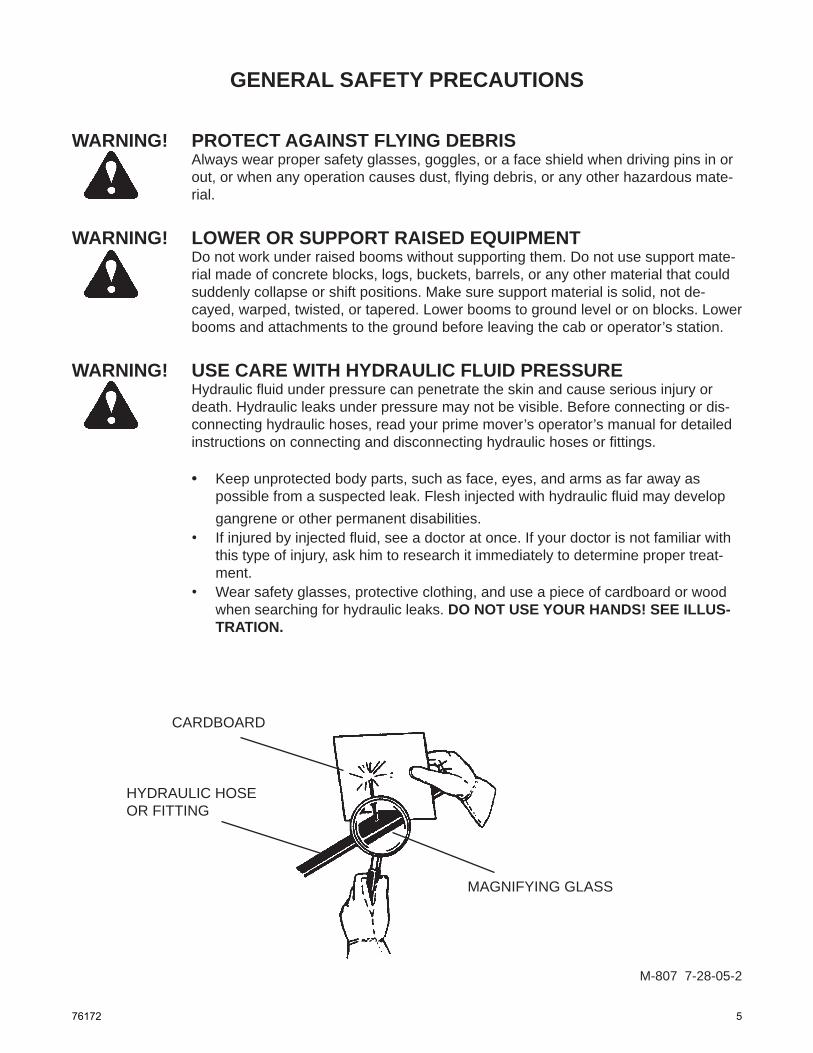
WARNING! USE CARE WITH HYDRAULIC FLUID PRESSUREHydraulic fl uid under pressure can penetrate the skin and cause serious injury or death. Hydraulic leaks under pressure may not be visible. Before connecting or dis-connecting hydraulic hoses, read your prime mover’s operator’s manual for detailed instructions on connecting and disconnecting hydraulic hoses or fi ttings.
• Keep unprotected body parts, such as face, eyes, and arms as far away as possible from a suspected leak. Flesh injected with hydraulic fl uid may develop gangrene or other permanent disabilities.
• If injured by injected fl uid, see a doctor at once. If your doctor is not familiar with this type of injury, ask him to research it immediately to determine proper treat-ment.
• Wear safety glasses, protective clothing, and use a piece of cardboard or wood when searching for hydraulic leaks. DO NOT USE YOUR HANDS! SEE ILLUS-TRATION.
CARDBOARD
HYDRAULIC HOSEOR FITTING
MAGNIFYING GLASS
M-807 7-28-05-2
76172 5
GENERAL SAFETY PRECAUTIONS
M-808 7-28-05-2
WARNING! DO NOT MODIFY MACHINE OR ATTACHMENTSModifi cations may weaken the integrity of the attachment and may impair the func-tion, safety, life, and performance of the attachment. When making repairs, use only the manufacturer’s genuine parts, following authorized instructions. Other parts may be substandard in fi t and quality. Never modify any ROPS (Roll Over Protection Structure) or FOPS (Falling Object Protective Structure) equipment or device. Any modifi cations must be authorized in writing by the manufacturer.
WARNING! SAFELY MAINTAIN AND REPAIR EQUIPMENT• Do not wear loose clothing or any accessories that can catch in moving parts. If
you have long hair, cover or secure it so that it does not become entangled in the equipment.
• Work on a level surface in a well-lit area.• Use properly grounded electrical outlets and tools.• Use the correct tools for the job at hand. Make sure they are in good condition for
the task required.• Wear the protective equipment specifi ed by the tool manufacturer.
SAFELY OPERATE EQUIPMENTDo not operate equipment until you are completely trained by a qualifi ed operator in how to use the controls, know its capabilities, dimensions, and all safety require-ments. See your machine’s manual for these instructions.• Keep all step plates, grab bars, pedals, and controls free of dirt, grease, debris,
and oil.• Never allow anyone to be around the equipment when it is operating.• Do not allow riders on the attachment or the prime mover.• Do not operate the equipment from anywhere other than the correct operator’s
position. • Never leave equipment unattended with the engine running, or with this attach-
ment in a raised position.• Do not alter or remove any safety feature from the prime mover or this attach-
ment.• Know your work site safety rules as well as traffi c rules and fl ow. When in doubt
on any safety issue, contact your supervisor or safety coordinator for an explana-tion.
6 76172

EQUIPMENT SAFETY PRECAUTIONS
WARNING! KNOW WHERE UTILITIES AREObserve overhead electrical and other utility lines. Be sure equipment will clear them. When digging, call your local utilities for location of buried utility lines, gas, water, and sewer, as well as any other hazard you may encounter.
OPERATING THE PRIME MOVERAvoid steep hillside operation, which could cause the prime mover to over-turn. Extreme caution should be used when working along the top of banks or slopes. Keep away from the edge.
When operating on a slope, keep the load low, and proceed with extreme caution. Do not drive ACROSS a steep slope - drive straight up and down. With a LOADED attachment - face the attachment and load uphill. With an EMPTY attachment - face the attachment downhill.
WORKING WITH THE TRUSS BOOM• Never use your attachment for a work platform or personnel carrier.• Specifi ed lift capacities must not be exceeded, otherwise machine stability
is not suffi cient. Always observe lift capacity limits listed in machine speci-fi cations. The cable anchor is not intended to hold rated load. Always keep a mini-mum of fi ve (5) wraps of cable on the drum.Always ensure the clutch is fully engaged before lifting or pulling a load.Make sure the worm brake is adjusted properly for the load being lifted.
• An operator must not use drugs or alcohol, which can change his or her alertness or coordination. An operator taking prescription or over-the-counter drugs should seek medical advice on whether or not he or she can safely operate equipment.
• Always check locking pins before operating any attachment. • Never lift, move, or swing a loaded attachment over anyone.• Do not use the truss boom for towing or pulling horizontally.• Don’t obstruct your vision when traveling or working. Carry the attachment
low for maximum stability and visibility.
WARNING! LARGE OR LOOSE OBJECTSUse extreme caution when lifting large and/or loose objects. Lifting too high or rolling the boom back could result in these objects swinging. Swinging loads can cause vehicle tipover, which can result in serious injury or death.
•
••
M-1264 3-31-06
76172 7

8 76172

INSTALLATION AND OPERATION
M-538 3-31-06-2
ATTACHING AND DETACHING EQUIPMENTPlease see your vehicle operator’s manual for instructions on attaching and detaching your equipment.
OPERATING EQUIPMENTRead all Safety Precautions before operating your new attachment. If a load chart is available, place it inside the operating machine for safe lift capacity limits. The 3’ truss boom is rated at 4000 pounds (1814 kg) lift capacity and the 12’ truss boom is rated at 2000 pounds (907 kg) lift capacity; these lift capacities should never be exceeded.
Refer to your machine operator’s manual for attachment operation.
WARNING!
BREAKING-IN THE ATTACHMENT
This product is not designed or intended to lift personnel.
Do not use for towing or pulling horizontally.
Keep all persons and objects clear while any part of this machine is in motion.
The cable anchor is not intended to hold rated load. Always keep a minimum of fi ve (5) wraps of cable on the drum.
Always ensure the clutch is fully engaged before lifting or pulling a load.
Change oil every six (6) months; use EP 140 or equivalent.
If so equipped, lubricate the bushings weekly.
Use extreme caution when lifting large and/or loose objects. Lifting too high or rolling the boom back could result in these objects swinging. Swinging loads can cause vehicle tip-over, which can result in serious injury or death.
Do not overspeed the winch during cable installation.
To ensure optimum winch performance and life, run at one-half (½) rated load and line speed for the fi rst thirty minutes of operation.
Make sure the worm brake is adjusted properly for the load being lifted.
See the “Tulsa Winch Operating & Safety Manual” for brake information.
76172 9
TULSA WINCH OPERATING & SAFETY MANUAL
M-558 3-10-06-2
The following are excerpts from the Tulsa Winch Operating and Safety Manual. We have incorporated these into this manual in an effort to keep all Safety, Operational, and Maintenance information in one document.
INTRODUCTIONThank you for purchasing a new Tulsa Winch. We are proud of our products and are certain that they will perform your winch tasks properly. However, we do ask that you take a few minutes to read and thoroughly understand this booklet. Also, if you have new operators assigned to the winch, make sure that they read and understand it. Because of the large number of models we manufacture, we are unable to show parts lists for every model in this booklet. If you want or need parts lists, please write or call us at the address at the end of this section.
WINCH BREAK-INWinches, like any other kind of machinery, require a “break in” to perform well and to maximize their life. The fol-lowing guidelines should be used for breaking-in Tulsa winches.
Use extreme care when fi rst spooling cable onto the winch. Do NOT run the winch at high speeds when perform-ing this operation. Make sure that the cable is unrolled in a line (to prevent kinks), and SLOWLY inhaul the winch to install the cable. Do not exceed one-half rated load or one half rated linespeed for the fi rst thirty minutes of operation. This will en-sure that the worm and gear have an opportunity to wear-in properly. Periodically, check the gearbox for tempera-ture rises, and allow the winch to cool down between pulls. Worm gear winches are designed and intended for intermittent duty applications only; using them in extremely long pulls may generate excessive heat and shorten the life of the winch.
WINCH OPERATIONTo familiarize yourself with the winch, run it for a few minutes to understand the controls and the “feel” of the winch. Pay particular attention to the controls and how they operate. If the winch has air controls on the brake or clutch, or both, operate them to see how they work and the direction of activation of the controls. If the winch is hydraulically powered, make sure you understand which way the winch will rotate when the control lever is moved.
• Tulsa winches are not to be used to lift, hoist, or move people. If your task involves lifting or moving people, you MUST use the proper equipment, not this winchCable anchors on Tulsa winches are not designed to hold the rated load of the winch. You must keep at least fi ve (5) wraps of cable on the drum to insure that the cable doesn’t come loose.
• Stay clear of suspended loads and of cable under tension. A broken cable or dropped load can cause serious injury or death.
• Make sure that all equipment, including the winch and cable, is maintained properly. Pay especially close attention to the clutch, making sure that it fully engages when shifted. Do not attempt to disengage the clutch when a load is on the winch.
• Winches which are not equipped with automatic worm brakes should never be used to lift loads.Avoid shock loads. This type of load imposes a strain on the winch many times the actual weight of the load and can cause failure of the cable or of the winch.
•
•
WARNING!
FAILURE TO HEED THE FOLLOWING WARNINGSMAY RESULT IN SERIOUS INJURY OR DEATH!
10 76172

WINCH OPERATION (Continued) Always make sure that all people are clear of the load and of the cable area before beginning a winching opera-tion. A broken cable can fl y in any direction.
If you are using a mechanically powered winch, learn to pay close attention to the truck engine to sense possible overload. If using a hydraulic winch, do not attempt to defeat the relief valve. If you have any doubts about the ca-pability of the winch to lift or move a load, either put a “snatch block” in the line or get a bigger piece of equipment.
The typical winch operating cycle consists of the following steps:
(a) Disengaging the winch drum clutch and pulling off enough cable to allow hooking the load. If the winch is equipped with a manually operated drum brake, use it to keep the cable from “bird’s nesting” while being pulled off. DO NOT get into the habit of powering off cable; all this does is shorten the life of the winch, espe-cially the winch brake.
NOTE: The drum brake is for free-spooling cable only. It is not intended to be a load-holding brake, and must not be used as such.
(b) After hooking to the load, engage the drum clutch and release the drum brake, if the winch is so equipped. Make sure the clutch is fully engaged.
(c) Begin winching the load slowly, watching carefully to insure that the load is moving normally and that no one is in the immediate area of the load or of the cable.
(d) When the load is positioned where you want it, stop the winch. If the load is suspended, the automatic worm brake will hold it until you are ready to lower it.
CABLE CONSIDERATIONS
WINCH MAINTENANCEA winch, like other types of machinery, needs to have regular maintenance if it is to perform properly, give last-ing value, and provide safe winching. Good maintenance consists of two parts, a daily inspection and a periodic servicing. Each day, or after every one hour of winch use, the following items should be inspected and adjusted, if necessary:
If the winch is mechanically driven, check all drive components for alignment and tight mounting. If it is hydraulically driven, check for leaks and for proper fl uid level in the hydraulic reservoir.Check the cable for excessive wear, for broken strands, and lubrication.Check the automatic worm brake for proper adjustment and adjust it if necessary.Check the drum clutch to make sure it is fully engaging when shifted in. Make adjustments if necessary.
1.
2.3.4.
Model Cable Size (Inches) 5 3/8 938 7/16 1138 7/16 1000 7/16 1200 1/2 10 1/2 12 1/2 18 5/8 18G 5/8 19 5/8 23 5/8 24 3/4 34 3/4 64 7/8 70 1 75 1 80 1
M-559 3-10-06-2
As the number of layers of cable on a winch increases, the rated capacity of the winch goes down. If you are operating at near the top of the drum fl anges, the effective rating of the winch is about half of what it is on the fi rst layer. You should, therefore, only keep as much cable on the winch as you need for your job.
Never use larger or smaller cable on your winch than is recommended for it. The use of larger cable will not allow you to pull larger loads and may, in fact, break easier than the proper size cable. The use of smaller cable may overheat the winch due to the increased running time with more cable.
The attached chart shows the recommended cable sizes for Tulsa winches.
Consult your local cable supplier for recommendations on the best type of cable and hardware to use in your specifi c application.
TULSA WINCH OPERATING & SAFETY MANUAL
76172 11
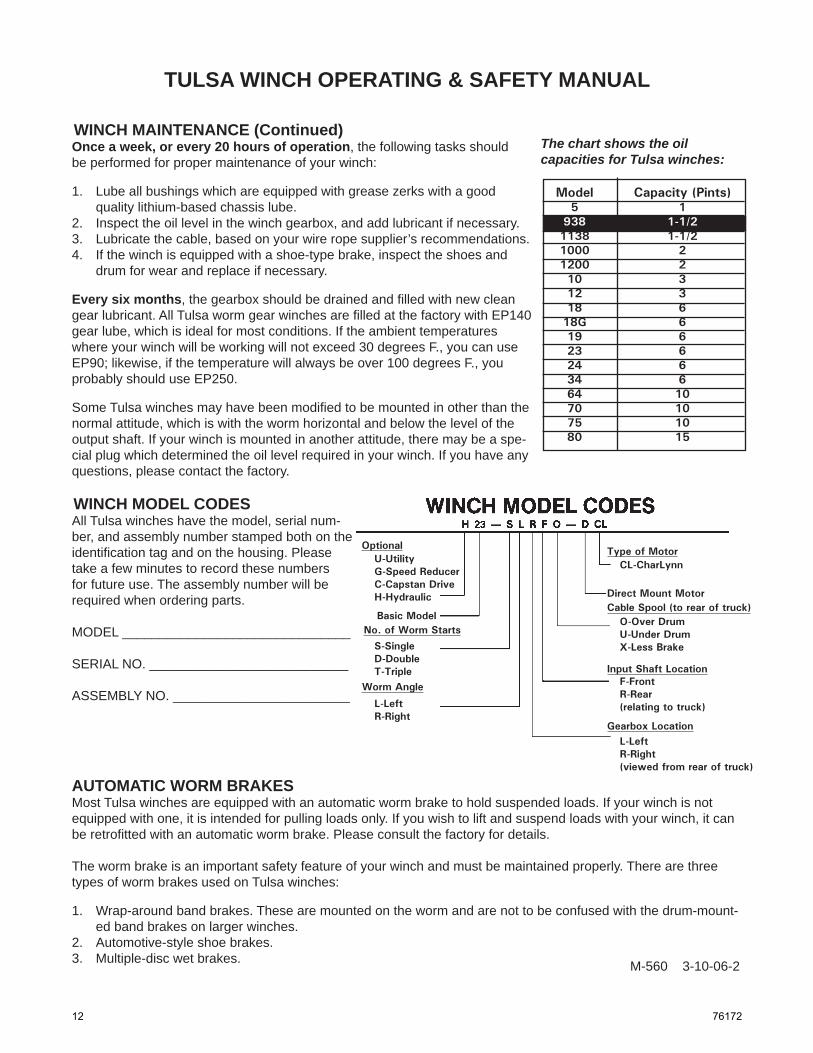
WINCH MAINTENANCE (Continued)Once a week, or every 20 hours of operation, the following tasks should be performed for proper maintenance of your winch:
Lube all bushings which are equipped with grease zerks with a good quality lithium-based chassis lube.Inspect the oil level in the winch gearbox, and add lubricant if necessary.Lubricate the cable, based on your wire rope supplier’s recommendations.If the winch is equipped with a shoe-type brake, inspect the shoes and drum for wear and replace if necessary.
Every six months, the gearbox should be drained and fi lled with new clean gear lubricant. All Tulsa worm gear winches are fi lled at the factory with EP140 gear lube, which is ideal for most conditions. If the ambient temperatures where your winch will be working will not exceed 30 degrees F., you can use EP90; likewise, if the temperature will always be over 100 degrees F., you probably should use EP250.
Some Tulsa winches may have been modifi ed to be mounted in other than the normal attitude, which is with the worm horizontal and below the level of the output shaft. If your winch is mounted in another attitude, there may be a spe-cial plug which determined the oil level required in your winch. If you have any questions, please contact the factory.
1.
2.3.4.
The chart shows the oil capacities for Tulsa winches:
Model Capacity (Pints) 5 1 938 1-1/2 1138 1-1/2 1000 2 1200 2 10 3 12 3 18 6 18G 6 19 6 23 6 24 6 34 6 64 10 70 10 75 10 80 15
WINCH MODEL CODESAll Tulsa winches have the model, serial num-ber, and assembly number stamped both on the identifi cation tag and on the housing. Please take a few minutes to record these numbers for future use. The assembly number will be required when ordering parts.
MODEL _______________________________
SERIAL NO. ___________________________
ASSEMBLY NO. ________________________
Optional Type of Motor
Worm Angle
No. of Worm Starts
Cable Spool (to rear of truck)
Input Shaft Location
Gearbox Location
Direct Mount Motor
U-UtilityG-Speed ReducerC-Capstan DriveH-Hydraulic
Basic Model
S-SingleD-DoubleT-Triple
L-LeftR-Right
CL-CharLynn
O-Over DrumU-Under DrumX-Less Brake
F-FrontR-Rear(relating to truck)
L-LeftR-Right(viewed from rear of truck)
AUTOMATIC WORM BRAKESMost Tulsa winches are equipped with an automatic worm brake to hold suspended loads. If your winch is not equipped with one, it is intended for pulling loads only. If you wish to lift and suspend loads with your winch, it can be retrofi tted with an automatic worm brake. Please consult the factory for details.
The worm brake is an important safety feature of your winch and must be maintained properly. There are three types of worm brakes used on Tulsa winches:
Wrap-around band brakes. These are mounted on the worm and are not to be confused with the drum-mount-ed band brakes on larger winches.Automotive-style shoe brakes.Multiple-disc wet brakes.
1.
2.3. M-560 3-10-06-2
TULSA WINCH OPERATING & SAFETY MANUAL
12 76172

AUTOMATIC WORM BRAKES (Continued)Each of these worm brakes is designed to operate in the same manner. As a load is hauled in, the brake is released and the load is moved or raised. As the load is stopped, the brake engages and prevents it from falling. When the operator begins to pay out cable to lower the load, he must overcome the drag of the brake to lower the load.
In order for the brake to operate properly, it must be set to engage in the payout mode. To check this, run the winch for one minute under no load in both directions at low speeds. If there is evidence of heat build-up in the payout direction, the brake is installed properly. If the heat rise occurs in the inhaul direction, the brake is installed backward and must be changed.
Most winches are set up to spool over the drum to the load. You can check your model code to determine this. If the winch is set up in this manner and you decide to spool the cable under the drum, you must reverse the direc-tion of brake engagement.
The most common brake for Tulsa winches is the automotive-style shoe brake. This brake uses two shoes in a brake drum to hold winch loads. Models 10 through 34 with shoe brakes have a reversible cam; the 64, 70, and 80 require installation of a new cam to change the direction of braking. The illustration on the right shows the end cover of the typical shoe brake and how to adjust it.
To tighten the brake, loosen the two capscrews in the slotted holes and rotate the brake in the direction shown. If the brake on a Model 10 through 34 needs to reversed, remove those same two capscrews, rotate the cam 60 degrees in the loosening direction, and reinstall the capscrews in the new set of holes which have just been revealed. After adjustment, be sure to re-tighten the cam capscrews securely.
Another type of brake, used on the Models 5, 6, 8 and some older winches is the band brake. Two assemblies of the band brake are shown to the right, with the cover removed to view the interior.
The direction in which this brake works can be reversed by removing the band from the brake, turning it over, and reinstalling it.
The Models 938, 1138, 1060, and 1242 are equipped with an adjustable, multiple disc oil brake. This brake is adjusted by loos-ening the jam nut and turning the capscrew inward.
Some versions of the Models 10 through 80 are equipped with a multiple disc oil brake which is not adjustable. These winches can be identifi ed by the warning on the cover.
CAUTION DURING REMOVAL!SPRING LOADED COVER!
These brakes require no regular adjustment. To service them, remove two capscrews 180 degrees from each other and install new capscrews which are 1” longer. Slowly, evenly remove the other capscrews until there is no tension on the brake spring. The direction of braking for all multiple disc brakes can be changed by removing the cam clutch, turning it over, and re-installing it. For detailed service instructions, contact your Tulsa Winch distributor or the factory.
M-561 3-10-06-2
TULSA WINCH OPERATING & SAFETY MANUAL
76172 13

BRAKE ADJUSTMENTIn general, worm brakes on Tulsa winches should only be adjusted enough to hold the load you are currently working with. Over adjust-ment will result in excessive heat generation and brake wear. The most positive way to insure proper brake adjustment is to lift a test load just barely off the ground. Jog the winch out, and see if the brake holds. It if doesn’t, tighten the brake slightly and try it again. If the brake is tight-ened completely and the load still drifts, the brake must be serviced. DO NOT use the winch to lift loads with a worn brake.
If the input to the winch is accessible and a torque wrench can be put on it, the brake can be set with this torque wrench. The table on the right shows the torque values for all models based on rated linepull.
LIMITED WARRANTY Tulsa Winch expressly warrants its products against defects in material and workmanship under normal and ordinary use and service for a period of One (1) year from the date of purchase from Tulsa Winch or any autho-rized distributor of Tulsa Winch products. This warranty is not applicable to product failure due to improper operation or usage, misapplication, or employment for other than normal ordinary purposes.
BUYER’S SOLE AND EXCLUSIVE REMEDY IN THE EVENT OF A DEFECT IS EXPRESSLY LIMITED TO THE REPAIR OR REPLACEMENT OF THE PRODUCT, OR THE REFUND OF THE PURCHASE PRICE, AT THE SOLE ELECTION OF TULSA WINCH. Written notice and explanation of the circumstance of any claim that a product has proven defective in material and workmanship should be given promptly by the Buyer to Tulsa Winch. Tulsa Winch requires proof of date of purchase and reserves the right to inspect any product claimed to be defective under this warranty.
EXCEPT AS SPECIFICALLY PROVIDED FOR IN THIS MANUFACTURER’S LIMITED WARRANTY, THERE ARE NO OTHER WARRANTIES EXPRESS OR IMPLIED INCLUDING BUT NOT LIMITED TO ANY IMPLIED WARRANTIES OF MERCHANTABILITY OR FITNESS FOR A PARTICULAR PURPOSE OR USE. IN NO EVENT SHALL TULSA WINCH BE LIABLE FOR LOSS OF PROFITS, INDIRECT, INCIDENTAL, SPECIAL, CONSE-QUENTIAL, OR OTHER SIMILAR DAMAGES ARISING OUT OF ANY BREACH OF THIS AGREEMENT, OB-LIGATIONS UNDER THE AGREEMENT, NEGLIGENCE OF STRICT LIABILITY. TULSA WINCH MAKES NO WARRANTY, EXPRESS OR IMPLIED, FOR A MINIMUM LENGTH OF SERVICE OR USE OF ANY TULSA WINCH PRODUCT. TULSA WINCH SHALL HAVE NO OBLIGATION TO REPAIR OR REPLACE ITEMS WHICH BY THEIR NATURE ARE EXPENDABLE.
TULSA WINCH · P.O. BOX 471617 · TULSA OKLAHOMA 74147 · PH: 918-663-5744 · FAX: 918-627-3221
Model Brake Torque (Lb.Ft.) 5 3 938 3 1138 3 1000 3 1200 4 10 32 12 32 18 50 18G 50 19 50 23 50 24 70 34 70 64 120 70 140 75 140 80 185
M-562 3-10-06-2
TULSA WINCH OPERATING & SAFETY MANUAL
14 76172

GENERAL INFORMATIONRegular maintenance is the key to long equipment life and safe operation. Maintenance re-quirements have been kept to an absolute minimum. However, it is very important that these maintenance functions be performed as described in this section
DAILY (OR AFTER EVERY ONE HOUR OF WINCH USE)• Check all bolts and nuts for tightness.• Replace any missing bolts or nuts with approved replacement parts.• Check hydraulic system for hydraulic oil leaks. See procedure below.• Visually inspect the machine for worn parts or cracked welds, and repair as necessary.
See “Winch Maintenance” in the “Tulsa Winch Operating & Safety Manual”.
WARNING! Escaping fl uid under pressure can have suffi cient force to penetrate the skin, causing serious personal injury. Fluid escaping from a very small hole can be almost invisible. Use a piece of cardboard or wood, rather than hands to search for suspected leaks.
Keep unprotected body parts, such as face, eyes, and arms as far away as possible from a suspected leak. Flesh injected with hydraulic fl uid may develop gangrene or other permanent disabilities.
If injured by injected fl uid, see a doctor at once. If your doctor is not familiar with this type of injury, ask him or her to research it immediately to determine proper treatment.
WEEKLY (OR AFTER EVERY 20 HOURS OF OPERATION)See “Winch Maintenance” in the “Tulsa Winch Operating & Safety Manual”.
EVERY SIX MONTHSSee “Winch Maintenance” in the “Tulsa Winch Operating & Safety Manual”.
•
•
•
M-1262 3-31-06
MAINTENANCE & SERVICE
IMPORTANT: When replacing parts, use only factory approved replacement parts. Manu-facturer will not claim responsibility for use of unapproved parts or accessories and/or other damages as a result of their use.
CARDBOARD
HYDRAULIC HOSE OR FITTING MAGNIFYING GLASS
76172 15

16 76172

STORAGE
GENERAL INFORMATION
The following storage procedure will help you to keep your attachment in top condition. It will also help you get off to a good start the next time your equipment is needed. We therefore strongly recommend that you take the extra time to follow these procedures whenever your attachment will not be used for an extended period of time.
PREPARATION FOR STORAGE
1. Clean the attachment thoroughly, removing all mud, dirt, and grease.
2. Inspect for visible signs of wear, breakage, or damage. Order any parts required, and make the necessary repairs, to avoid delays when starting next season.
3. Tighten all loose nuts, capscrews, and hydraulic connections.
4. Lubricate all grease fi ttings.
5. Connect the hydraulic couplers together to protect the hydraulic system from contami-nates.
6. Touch up all unpainted and exposed areas with paint, to prevent rust.
7. Replace decals, if damaged or in unreadable condition.
8. Store the attachment in a dry and protected place, with a cover, if possible. Leaving the attachment outside will materially shorten its life.
REMOVING FROM STORAGE
1. Remove all protective coverings.
2. Check hydraulic hoses for deterioration, and replace if necessary.
M-1263 3-10-06
76172 17

18 76172

LIMITED WARRANTY
M-711 11-9-05-4
All new Major products are warranted to be free from defects in materials or workman-ship which may cause failure under normal usage and service, when used for the purpose intended.
In the event of failure within twelve (12) months from initial retail sale, lease or rental date (excluding cable, ground engaging parts such as sprockets, digging chain, bearings, teeth, tamping and demolition heads, blade cutting edges, pilot bits, auger teeth, auger heads & broom bristles), if after examination, The Major determines failure was due to defective ma-terial and/or workmanship, parts will be repaired or replaced. The Major may request defec-tive part or parts be returned prepaid to them for inspection at their place of business at Delhi, Iowa, or to a location specifi ed by The Major.
Any claims under this warranty must be made within fi fteen (15) days after the Buyer learns of the facts upon which such claim is based. All claims not made in writing and received by The Major within the time period specifi ed above shall be deemed waived.
THIS WARRANTY IS IN LIEU OF ALL OTHER WARRANTIES EXPRESSED OR IMPLIED, AND THERE ARE NO WARRANTIES OF MERCHANTABILITY OR OF FITNESS FOR A PARTICULAR PURPOSE. IN NO EVENT SHALL THE MAJOR BE LIABLE FOR CONSEQUENTIAL OR SPECIAL DAMAGE.
THE MAJOR'S LIABILITY FOR ANY AND ALL LOSSES AND DAMAGES TO BUY-ER, RESULTING FROM ANY CAUSE WHATSOEVER, INCLUDING THE MAJOR'S NEG-LIGENCE, IRRESPECTIVE OF WHETHER SUCH DEFECTS ARE DISCOVERABLE OR LATENT, SHALL IN NO EVENT EXCEED THE PURCHASE PRICE OF THE PARTICULAR PRODUCTS WITH RESPECT TO WHICH LOSSES OR DAMAGES ARE CLAIMED, OR, AT THE ELECTION OF THE MAJOR, THE REPAIR OR REPLACEMENT OF DEFECTIVE OR DAMAGED PRODUCTS.
76172 19

20 76172

M-1127 10-4-06-2
PARTS
The following section contains detailed diagrams and parts lists which include your attachment. Please use these diagrams and parts lists to locate replacement parts, prior to contacting the parts department.
When servicing your attachment, remember to use only original manufacturer replace-ment parts. Substitute parts may not meet the standards required for safe, dependable opera-tion.
To facilitate parts ordering, have the model and serial number of your product ready, to ensure that you receive the correct parts for your specifi c attachment.
The model and serial number for your attachment should be recorded in the space provided on the cover of this manual. This information may be obtained from the serial number identifi cation plate located on your attachment. See the parts diagram for your attachment for the location.
NOTE: Most daily and emergency orders received by 2:00 P.M. will be shipped the same day received, with “Emergency-Machine-Down” orders receiving fi rst priority.
PARTS DEPARTMENT(563) 922-2981(800) 922-2981
We Encourage Fax Orders(563) 922-2593
76172 21
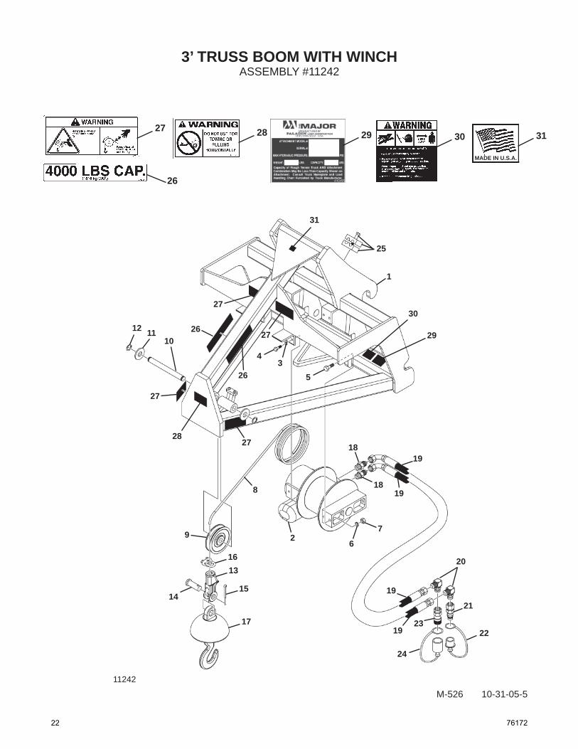
3’ TRUSS BOOM WITH WINCHASSEMBLY #11242
M-526 10-31-05-5
26
MADE IN U.S.A.
29
1
4
5
5
3
25
31302827
31
30
2927
26
27
2612 1110
27
2827
8
9 26
7
18
18
19
19
20
19
1923
21
22
24
17
15
1316
14
11242
22 76172

3’ TRUSS BOOM WITH WINCH
M-527 10-31-05-6
ITEM QTY. PART NO. DESCRIPTION
1 1 32047 3’ Truss Boom Frame 2 1 14434 Truss Boom Winch 3 4 1503 .38” Lock Washer 4 4 1043 .38” UNC x 1.00” Hex Capscrew 5 2 1091 .50” UNC x 1.75” Hex Capscrew
6 2 1505 .50” Lock Washer 7 2 1228 .50” Hex Nut 8 1 14435 Cable 9 1 14436 Pulley 10 1 14437 Pin, 1.00” x 9.32” 11 2 1706 1.00” Hard Flat Washer 12 2 1570 Snap Ring 13 1 14439 Socket Assembly, 3 Ton Wedge. Includes Items 14 & 15 14 1 NSS Pin 15 1 NSS Cotter Pin
16 1 14440 Cable Clamp 17 1 14438 Ball Swivel, With Safety Hook 18 2 3457 Straight Adapter 6MBo-6MJ 19 2 37899 Hose Assembly .38” x 32.00” 6FJX-6FJX 20 2 30142 90° Elbow 8MBo-6MJ
21 1 17139 Male Quick Coupler 22 1 51753 Dust Cap 23 1 17140 Female Quick Coupler 24 1 51754 Dust Plug 25 1 81358 Double Clamp
26 2 40603 Capacity Decal 27 4 40602 Rotating Part Danger Decal 28 1 40561 Do Not Tow Warning Decal 29 1 ----- Serial Number Identifi cation Tag Location 30 1 40151 High Pressure Fluid Warning Decal 31 1 4338 Made in USA Decal NSS-Not Serviced Separately
ASSEMBLY #11242
76172 23

3’ TRUSS BOOM WITH WINCHASSEMBLY #12340
M-1243 3-31-06
26
MADE IN U.S.A.
30
1
4
5
5
3
25
32312928
32
31
30
27
26
12
11
10
2928
8
9
26
7
18
18
19
19
2020
21
23
17
1513
16
14
27
28
28
27
24
22
19
19
24 76172

3’ TRUSS BOOM WITH WINCH
M-1244 3-31-06
ITEM QTY. PART NO. DESCRIPTION
1 1 305037 3’ Truss Boom Frame 2 1 14434 Truss Boom Winch 3 4 1503 .38” Lock Washer 4 4 1043 .38” UNC x 1.00” Hex Capscrew 5 2 1091 .50” UNC x 1.75” Hex Capscrew
6 2 1505 .50” Lock Washer 7 2 1228 .50” UNC Hex Nut 8 1 14435 Cable 9 1 14436 Pulley 10 1 14437 Pin, 1.00” x 9.32” 11 2 1706 1.00” Hard Flat Washer 12 2 1570 Snap Ring 13 1 14439 Socket Assembly, 3 Ton Wedge. Includes Items 14 & 15 14 1 NSS Pin 15 1 NSS Cotter Pin
16 1 14440 Cable Clamp 17 1 14438 Ball Swivel, With Safety Hook 18 2 3457 Straight Adapter 6MBo-6MJ 19 2 37852 Hose Assembly .38” x 39.00” 6FJX-6FJX 90° 20 2 3269 Straight Connector 8MBo-6MJ
21 1 84923 Male Quick Coupler 22 1 32549 Dust Cap 23 1 84928 Female Quick Coupler 24 1 32548 Dust Plug 25 1 81358 Double Clamp
26 2 40603 Capacity Decal 27 3 40502 Major Logo, Medium 28 4 40602 Rotating Part Warning Decal 29 1 40561 Do Not Tow Warning Decal 30 1 ----- Serial Number Identifi cation Tag Location 31 1 40151 High Pressure Fluid Warning Decal 32 1 4338 Made in USA Decal NSS-Not Serviced Separately
ASSEMBLY #12340
76172 25

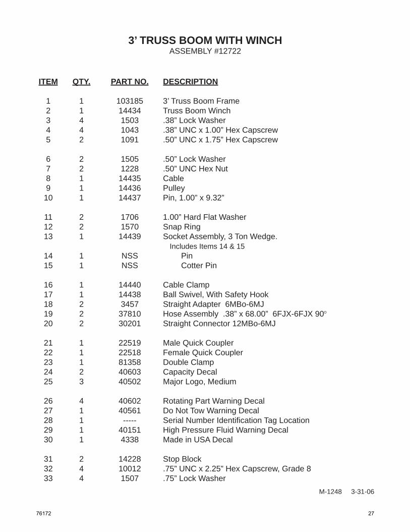
3’ TRUSS BOOM WITH WINCHASSEMBLY #12722
M-1247 3-31-06
24
MADE IN U.S.A.
28
1
4
5
5
3
30292726
30
29
2625
24
12
11
10
2726
8
9
26
7
18
18
19
19
2020
21
22
17
1513
16
14
25
28
26
25
19
19
3233
31
23
26 76172
3’ TRUSS BOOM WITH WINCH
M-1248 3-31-06
ITEM QTY. PART NO. DESCRIPTION
1 1 103185 3’ Truss Boom Frame 2 1 14434 Truss Boom Winch 3 4 1503 .38” Lock Washer 4 4 1043 .38” UNC x 1.00” Hex Capscrew 5 2 1091 .50” UNC x 1.75” Hex Capscrew
6 2 1505 .50” Lock Washer 7 2 1228 .50” UNC Hex Nut 8 1 14435 Cable 9 1 14436 Pulley 10 1 14437 Pin, 1.00” x 9.32” 11 2 1706 1.00” Hard Flat Washer 12 2 1570 Snap Ring 13 1 14439 Socket Assembly, 3 Ton Wedge. Includes Items 14 & 15 14 1 NSS Pin 15 1 NSS Cotter Pin
16 1 14440 Cable Clamp 17 1 14438 Ball Swivel, With Safety Hook 18 2 3457 Straight Adapter 6MBo-6MJ 19 2 37810 Hose Assembly .38” x 68.00” 6FJX-6FJX 90° 20 2 30201 Straight Connector 12MBo-6MJ
21 1 22519 Male Quick Coupler 22 1 22518 Female Quick Coupler 23 1 81358 Double Clamp 24 2 40603 Capacity Decal 25 3 40502 Major Logo, Medium
26 4 40602 Rotating Part Warning Decal 27 1 40561 Do Not Tow Warning Decal 28 1 ----- Serial Number Identifi cation Tag Location 29 1 40151 High Pressure Fluid Warning Decal 30 1 4338 Made in USA Decal
31 2 14228 Stop Block 32 4 10012 .75” UNC x 2.25” Hex Capscrew, Grade 8 33 4 1507 .75” Lock Washer
ASSEMBLY #12722
76172 27
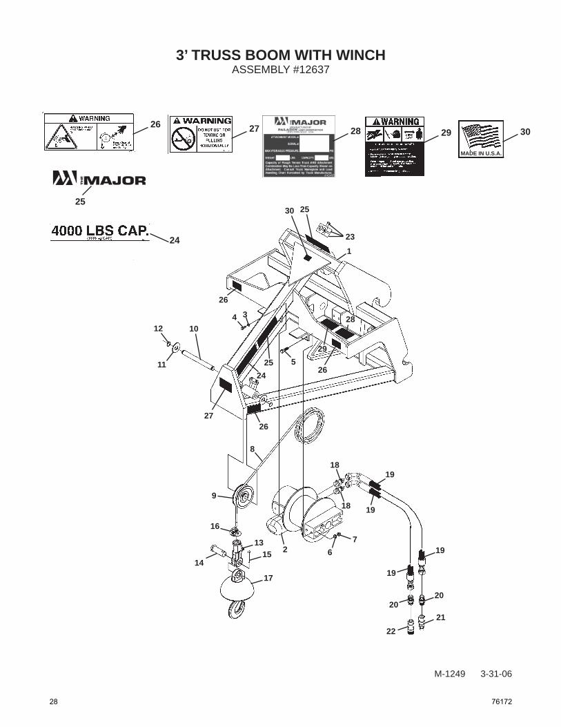
3’ TRUSS BOOM WITH WINCHASSEMBLY #12637
M-1249 3-31-06
24
MADE IN U.S.A.
28
1
4
5
5
3
23
30292726
30
29
2625
24
12
11
10
2726
8
9
2 67
18
18
19
19
2020
2122
17
1513
16
14
25
28
26
25
19
19
28 76172

3’ TRUSS BOOM WITH WINCH
M-1250 3-31-06
ITEM QTY. PART NO. DESCRIPTION
1 1 100721 3’ Truss Boom Frame 2 1 14434 Truss Boom Winch 3 4 1503 .38” Lock Washer 4 4 1043 .38” UNC x 1.00” Hex Capscrew 5 2 1091 .50” UNC x 1.75” Hex Capscrew
6 2 1505 .50” Lock Washer 7 2 1228 .50” UNC Hex Nut 8 1 14435 Cable 9 1 14436 Pulley 10 1 14437 Pin, 1.00” x 9.32” 11 2 1706 1.00” Hard Flat Washer 12 2 1570 Snap Ring 13 1 14439 Socket Assembly, 3 Ton Wedge. Includes Items 14 & 15 14 1 NSS Pin 15 1 NSS Cotter Pin
16 1 14440 Cable Clamp 17 1 14438 Ball Swivel, With Safety Hook 18 2 3457 Straight Adapter 6MBo-6MJ 19 2 37801 Hose Assembly .38” x 70.00” 6FJX-6FJX 90°, HS 20 2 3269 Straight Connector 8MBo-6MJ
21 1 14176 Male Quick Coupler 22 1 14175 Female Quick Coupler 23 1 81358 Double Clamp 24 2 40603 Capacity Decal 25 3 40502 Major Logo, Medium
26 4 40602 Rotating Part Warning Decal 27 1 40561 Do Not Tow Warning Decal 28 1 ----- Serial Number Identifi cation Tag Location 29 1 40151 High Pressure Fluid Warning Decal 30 1 4338 Made in USA Decal
ASSEMBLY #12637
76172 29
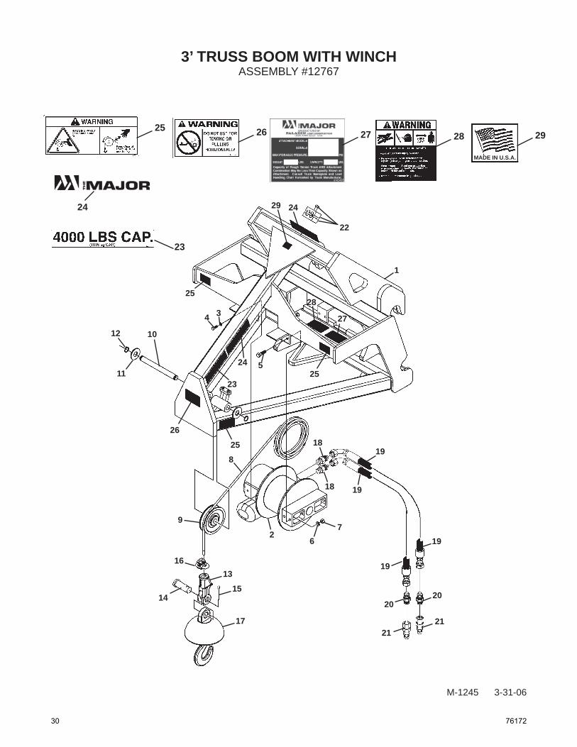
3’ TRUSS BOOM WITH WINCHASSEMBLY #12767
M-1245 3-31-06
23
MADE IN U.S.A.
27
1
4
5
5
3
22
29282625
29
28
2524
23
12
11
10
26
258
9
26
7
18
18
19
19
2020
2121
17
15
1316
14
24
27
25
24
19
19
30 76172
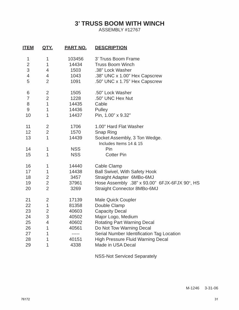
3’ TRUSS BOOM WITH WINCH
ITEM QTY. PART NO. DESCRIPTION
1 1 103456 3’ Truss Boom Frame 2 1 14434 Truss Boom Winch 3 4 1503 .38” Lock Washer 4 4 1043 .38” UNC x 1.00” Hex Capscrew 5 2 1091 .50” UNC x 1.75” Hex Capscrew
6 2 1505 .50” Lock Washer 7 2 1228 .50” UNC Hex Nut 8 1 14435 Cable 9 1 14436 Pulley 10 1 14437 Pin, 1.00” x 9.32” 11 2 1706 1.00” Hard Flat Washer 12 2 1570 Snap Ring 13 1 14439 Socket Assembly, 3 Ton Wedge. Includes Items 14 & 15 14 1 NSS Pin 15 1 NSS Cotter Pin
16 1 14440 Cable Clamp 17 1 14438 Ball Swivel, With Safety Hook 18 2 3457 Straight Adapter 6MBo-6MJ 19 2 37961 Hose Assembly .38” x 93.00” 6FJX-6FJX 90°, HS 20 2 3269 Straight Connector 8MBo-6MJ
21 2 17139 Male Quick Coupler 22 1 81358 Double Clamp 23 2 40603 Capacity Decal 24 3 40502 Major Logo, Medium 25 4 40602 Rotating Part Warning Decal 26 1 40561 Do Not Tow Warning Decal 27 1 ----- Serial Number Identifi cation Tag Location 28 1 40151 High Pressure Fluid Warning Decal 29 1 4338 Made in USA Decal NSS-Not Serviced Separately
ASSEMBLY #12767
M-1246 3-31-06
76172 31
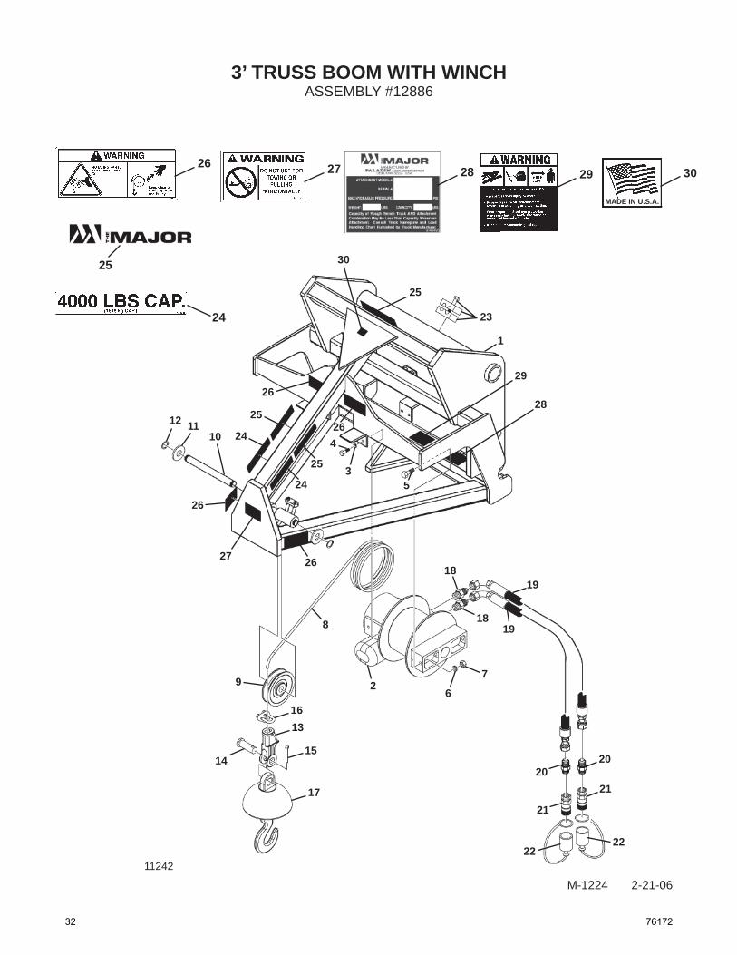
3’ TRUSS BOOM WITH WINCHASSEMBLY #12886
M-1224 2-21-06
24
MADE IN U.S.A.
28
1
4
5
5
3
23
30292726
30
29
28
26
24
26
2512 1110
26
27 26
8
9 26
7
18
18
19
19
21
21
2222
17
15
1316
14
11242
25
25
24
2020
25
32 76172

3’ TRUSS BOOM WITH WINCH
M-1225 2-21-06
ITEM QTY. PART NO. DESCRIPTION
1 1 106249 3’ Truss Boom Frame 2 1 14434 Truss Boom Winch 3 4 1503 .38” Lock Washer 4 4 1043 .38” UNC x 1.00” Hex Capscrew 5 2 1091 .50” UNC x 1.75” Hex Capscrew
6 2 1505 .50” Lock Washer 7 2 1228 .50” Hex Nut 8 1 14435 Cable 9 1 14436 Pulley 10 1 14437 Pin, 1.00” x 9.32” 11 2 1706 1.00” Hard Flat Washer 12 2 1570 Snap Ring 13 1 14439 Socket Assembly, 3 Ton Wedge. Includes Items 14 & 15 14 1 NSS Pin 15 1 NSS Cotter Pin
16 1 14440 Cable Clamp 17 1 14438 Ball Swivel, With Safety Hook 18 2 3457 Straight Adapter 6MBo-6MJ 19 2 38085 Hose Assembly .38” x 87.00” 6FJX-6FJX90º 20 2 3269 Straight Connector 8MBo-6MJ
21 2 84928 Female Quick Coupler 22 2 32548 Dust Plug 23 1 81358 Double Clamp 24 2 40603 Capacity Decal 25 3 40502 Major Logo, Medium
26 4 40602 Rotating Part Danger Decal 27 1 40561 Do Not Tow Warning Decal 28 1 ----- Serial Number Identifi cation Tag Location 29 1 40151 High Pressure Fluid Warning Decal 30 1 4338 Made in USA Decal NSS-Not Serviced Separately
ASSEMBLY #12886
76172 33

12’ TRUSS BOOM WITH WINCHASSEMBLY #11141
M-1125 11-16-05
25
MADE IN U.S.A.
28
1
4 5
5
3
25
30292726
30
29
31
12 1110
26
26
8
9
2 6
7
18
18
19
19
20
19
19 23
21
22
24
17
151316
14
31
28
26
3125
27
25
34 76172
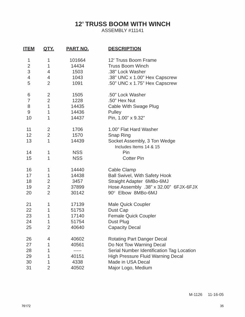
12’ TRUSS BOOM WITH WINCH
M-1126 11-16-05
ITEM QTY. PART NO. DESCRIPTION
1 1 101664 12’ Truss Boom Frame 2 1 14434 Truss Boom Winch 3 4 1503 .38” Lock Washer 4 4 1043 .38” UNC x 1.00” Hex Capscrew 5 2 1091 .50” UNC x 1.75” Hex Capscrew
6 2 1505 .50” Lock Washer 7 2 1228 .50” Hex Nut 8 1 14435 Cable With Swage Plug 9 1 14436 Pulley 10 1 14437 Pin, 1.00” x 9.32” 11 2 1706 1.00” Flat Hard Washer 12 2 1570 Snap Ring 13 1 14439 Socket Assembly, 3 Ton Wedge Includes Items 14 & 15 14 1 NSS Pin 15 1 NSS Cotter Pin
16 1 14440 Cable Clamp 17 1 14438 Ball Swivel, With Safety Hook 18 2 3457 Straight Adapter 6MBo-6MJ 19 2 37899 Hose Assembly .38” x 32.00” 6FJX-6FJX 20 2 30142 90° Elbow 8MBo-6MJ
21 1 17139 Male Quick Coupler 22 1 51753 Dust Cap 23 1 17140 Female Quick Coupler 24 1 51754 Dust Plug 25 2 40640 Capacity Decal
26 4 40602 Rotating Part Danger Decal 27 1 40561 Do Not Tow Warning Decal 28 1 ----- Serial Number Identifi cation Tag Location 29 1 40151 High Pressure Fluid Warning Decal 30 1 4338 Made in USA Decal 31 2 40502 Major Logo, Medium
ASSEMBLY #11141
76172 35

12’ TRUSS BOOM WITH WINCHASSEMBLY #11147
M-1255 3-31-06
25
MADE IN U.S.A.
28
1
5
5
32
30292726
31
31
2512
11
10
27 26
8
9
2 67
18
18
19
19
2123
24
2217
1513
16
14
26
31
19
19
26
2829
30
34
20 20
36 76172

12’ TRUSS BOOM WITH WINCH
M-1256 3-31-06
ITEM QTY. PART NO. DESCRIPTION
1 1 16801 12’ Truss Boom Frame 2 1 14434 Truss Boom Winch 3 4 1503 .38” Lock Washer 4 4 1043 .38” UNC x 1.00” Hex Capscrew 5 2 1091 .50” UNC x 1.75” Hex Capscrew
6 2 1505 .50” Lock Washer 7 2 1228 .50” UNC Hex Nut 8 1 14435 Cable 9 1 14436 Pulley 10 1 14437 Pin, 1.00” x 9.32” 11 2 1706 1.00” Hard Flat Washer 12 2 1570 Snap Ring 13 1 14439 Socket Assembly, 3 Ton Wedge Includes Items 14 & 15 14 1 NSS Pin 15 1 NSS Cotter Pin
16 1 14440 Cable Clamp 17 1 14438 Ball Swivel, With Safety Hook 18 2 3457 Straight Adapter 6MBo-6MJ 19 2 37810 Hose Assembly .38” x 68.00” 6FJX-6FJX 90° 20 2 3269 Straight Connector 8MBo-6MJ
21 1 84928 Female Quick Coupler 22 1 32548 Dust Plug 23 1 84923 Male Quick Coupler 24 1 32549 Dust Cap 25 2 40640 Capacity Decal
26 4 40602 Rotating Part Warning Decal 27 1 40561 Do Not Tow Warning Decal 28 1 ----- Serial Number Identifi cation Tag Location 29 1 40151 High Pressure Fluid Warning Decal 30 1 4338 Made in USA Decal
31 3 40502 Major Logo, Medium 32 1 81358 Double Clamp
ASSEMBLY #11147
76172 37

12’ TRUSS BOOM WITH WINCHASSEMBLY #12514
M-1251 4-4-06
24
MADE IN U.S.A.
27
1
5
5
23
29282625
29
30
2412
11
10
26 258
9
2 67
18
18
19
19
2121
22
2217
1513
16
14
25
30
19
19
25
2728
30
34
20 20
38 76172

12’ TRUSS BOOM WITH WINCH
M-1252 4-4-06
ITEM QTY. PART NO. DESCRIPTION
1 1 18258 12’ Truss Boom Frame 2 1 14434 Truss Boom Winch 3 4 1503 .38” Lock Washer 4 4 1043 .38” UNC x 1.00” Hex Capscrew 5 2 1091 .50” UNC x 1.75” Hex Capscrew
6 2 1505 .50” Lock Washer 7 2 1228 .50” UNC Hex Nut 8 1 14435 Cable 9 1 14436 Pulley 10 1 14437 Pin, 1.00” x 9.32” 11 2 1706 1.00” Hard Flat Washer 12 2 1570 Snap Ring 13 1 14439 Socket Assembly, 3 Ton Wedge Includes Items 14 & 15 14 1 NSS Pin 15 1 NSS Cotter Pin
16 1 14440 Cable Clamp 17 1 14438 Ball Swivel, With Safety Hook 18 2 3457 Straight Connector 6MBo-6MJ 19 2 38085 Hose Assembly .38” x 87.00” 6FJX-6FJX90° 20 2 3269 Straight Connector 8MBo-6MJ
21 2 84928 Female Quick Coupler 22 2 32548 Dust Plug 23 1 81358 Double Clamp 24 2 40640 Capacity Decal 25 4 40602 Rotating Part Warning Decal 26 1 40561 Do Not Tow Warning Decal
27 1 ----- Serial Number Identifi cation Tag Location 28 1 40151 High Pressure Fluid Warning Decal 29 1 4338 Made in USA Decal 30 3 40502 Major Logo, Medium
NSS-Not Serviced Separately
ASSEMBLY #12514
76172 39

12’ TRUSS BOOM WITH WINCHASSEMBLY #12746
M-1257 3-31-06
23
MADE IN U.S.A.
26
1
5
5
29
30272524
28
28
2312
11
10
25 24
8
9
2 67
18
18
19
19
21
22
17
1513
16
14
24
28
19
19
24
2627
30
34
2020
31
3233
40 76172
12’ TRUSS BOOM WITH WINCH
M-1258 3-31-06
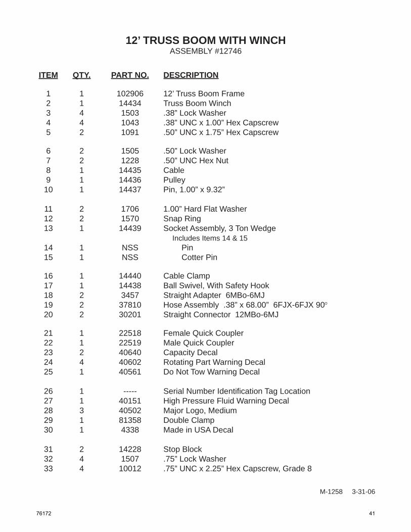
ITEM QTY. PART NO. DESCRIPTION
1 1 102906 12’ Truss Boom Frame 2 1 14434 Truss Boom Winch 3 4 1503 .38” Lock Washer 4 4 1043 .38” UNC x 1.00” Hex Capscrew 5 2 1091 .50” UNC x 1.75” Hex Capscrew
6 2 1505 .50” Lock Washer 7 2 1228 .50” UNC Hex Nut 8 1 14435 Cable 9 1 14436 Pulley 10 1 14437 Pin, 1.00” x 9.32” 11 2 1706 1.00” Hard Flat Washer 12 2 1570 Snap Ring 13 1 14439 Socket Assembly, 3 Ton Wedge Includes Items 14 & 15 14 1 NSS Pin 15 1 NSS Cotter Pin
16 1 14440 Cable Clamp 17 1 14438 Ball Swivel, With Safety Hook 18 2 3457 Straight Adapter 6MBo-6MJ 19 2 37810 Hose Assembly .38” x 68.00” 6FJX-6FJX 90° 20 2 30201 Straight Connector 12MBo-6MJ
21 1 22518 Female Quick Coupler 22 1 22519 Male Quick Coupler 23 2 40640 Capacity Decal 24 4 40602 Rotating Part Warning Decal 25 1 40561 Do Not Tow Warning Decal
26 1 ----- Serial Number Identifi cation Tag Location 27 1 40151 High Pressure Fluid Warning Decal 28 3 40502 Major Logo, Medium 29 1 81358 Double Clamp 30 1 4338 Made in USA Decal
31 2 14228 Stop Block 32 4 1507 .75” Lock Washer 33 4 10012 .75” UNC x 2.25” Hex Capscrew, Grade 8
ASSEMBLY #12746
76172 41

M-1360 10-4-06
P.O. Box 266Delhi, IA 52223-0266
(563) 922-2981(800) 922-2981
www.paladinbrands.com
42 76172