trusted wireless 2.0 wireless technologies in industrial
TRANSCRIPT

© 2018 PHOENIX CONTACT PHOENIX CONTACT • P.O. BOX 4100 • HARRISBURG, PA 17111-0100 Phone: 800-888-7388 • 717-944-1300 • Technical Service: 800-322-3225 • Fax: 717-944-1625
E-mail: [email protected] • Website: www.phoenixcontact.com
Wireless technologies in industrial automation
Year after year, more industrial applications are using
wireless technologies. Users benefit from this as wireless
solutions offer a higher degree of mobility and flexibility.
Often, one reason for using a wireless system is the fact
that this allows costs to be saved.
Factory and process automation industries primarily use
wireless technologies that can be operated without a
license. Due to national frequency regulation, only a few
frequency bands meet this requirement. Of the several so-
called ISM (Industrial Scientific Medical) bands that can be
used without a license, the popular 900 MHz band is used
only in North and South America, and the 2.4 GHz band is
used globally.
As these bands do not require licenses, they are utilized
frequently, and many systems have the potential to
be operating in the same band in a given region; thus,
coexistence is one of the vital properties of wireless
technologies.
INSIDE
Wireless technologies in industrial automation....................... 1-2 Areas of application for Trusted Wireless 2.0................................ 2
Rugged communication thanks to FHSS......................................... 3
Disturbances of the wireless signal.............................................. 3-4
Automatic and manual coexistence mechanisms........................ 5
Secure communication thanks .....................to encryption and authentication............................................................................... 5
Higher receiver sensitivity and adjustable data rates for increased range.......................................................................... 6-7
Increased robustness and coexistence with super heterodyne radio design.................................................................... 7
Flexible networks with automatic connection management..................................................................................... 7-8
Distributed network maintenance – faster and easier............. 9
Extensive diagnostic properties..................................................... 9
Adjustable to the desired application......................................... 10
Glossary.............................................................................................. 10
JUNE 2018
1
003932A
Created by: I/O & Networks Industrial Electronics DivisionPhoenix Contact Americas Regional Business Unit
Trusted Wireless 2.0 wireless technologies in industrial automation
Product Marketing Contact: Justin Shade
Product Marketing Specialist—Wireless
Phoenix Contact [email protected]

JUNE 2018
© 2018 PHOENIX CONTACT PHOENIX CONTACT • P.O. BOX 4100 • HARRISBURG, PA 17111-0100 003950A Phone: 800-888-7388 • 717-944-1300 • Technical Service: 800-322-3225 • Fax: 717-944-1625
E-mail: [email protected] • Website: www.phoenixcontact.com
2
Because the 2.4 GHz ISM band is used globally, users deal
with heavier congestion than with the 900 MHz band,
although there is more bandwidth available in the 2.4 GHz
band. However, the conditions for the attenuation of
electromagnetic waves are better in lower frequency ranges
(Figure 1). Therefore, higher frequencies will have reduced
range. The free space attenuation depends logarithmically
on the transmission frequency. This means that if one halves
the transmission frequency (e.g., from 868 MHz to 433
MHz), the free space attenuation reduces by 6 dB for the
same distance.
With a decrease in free space attenuation of 6 dB,
the range will potentially double with the transmission
power staying the same. This way, it is possible to overcome
longer ranges with lower frequencies.
In the following, the description of the Trusted Wireless 2.0
technology will refer to well-known wireless technologies
of the consumer and IT sector. With the adoption of
Bluetooth and WLAN for use in industrial environments,
we would like especially to outline the differences between
these technologies. A wireless technology – WirelessHART
– was also developed especially for the process industry.
Areas of application for Trusted Wireless 2.0
Trusted Wireless 2.0, a wireless technology developed
especially for industrial use and the technology that is used
in the Radioline platform, comes particularly suited for the
transmission of analog and digital I/O without wires or for
the transmission of small or medium data amounts – even
over large distances from a few hundred meters to several
kilometers/miles.
The main features of Trusted Wireless 2.0 include:
• Rugged communication with Frequency
Hopping Spread Spectrum
• Secure communication using 128-bit AES encryption and
authentication
• Long range due to high receiver sensitivity, variable data
transmission rates, and high transmission power (100 mW
for 2.4 GHz, 1 W for 900 MHz)
• Flexible network structures: point to point,
star, repeater
• Extensive diagnostic features
The following will explain these properties.
Figure 1: The free space attenuation increases in proportion to the frequency
JUNE 2018
© 2018 PHOENIX CONTACT PHOENIX CONTACT • P.O. BOX 4100 • HARRISBURG, PA 17111-0100 003950A Phone: 800-888-7388 • 717-944-1300 • Technical Service: 800-322-3225 • Fax: 717-944-1625
E-mail: [email protected] • Website: www.phoenixcontact.com
3
Rugged communication thanks to FHSS
Every user wants to use a reliable and rugged communication
connection for his/her application. However, the terms
“reliable” and “rugged” have the tendency to elicit a subjective
perception. Characteristics such as reliability, latency,
determinism, data throughput, etc., play – depending on the
application – an important role for the user. Generally, users
refer to this as “reliability.”
However, users should know and have the ability to
classify the real application requirements.
The available wireless technologies have different key aspects
and performances and should be selected according to the
application requirements.
Knowing which factors impede the “reliability” of a wireless
path and how the different wireless technologies deal with
these problems also plays a vital role in wireless technology
operation.
Two major factors can influence a wireless connection: first,
the disturbance of the wireless signal by other electromagnetic
waves, triggered by other wireless systems or unwanted
emissions of other electric devices (EMC disturbances);
secondly, “fading,” which occurs because of free space
attenuation, but most especially by reflections.
Disturbances of the wireless signal
Disturbance caused by other wireless systems or EMC disturbances
In the 900 MHz and 2.4 GHz bands, wireless systems benefit
from the fact that EMC disturbances caused by general
industrial applications do not reach this high-frequency range.
Frequency converters, ballasts, and other EMC-producing
devices, which usually pose a problem, do not disturb the GHz
band. Their energy transmissions play a role for frequencies in
the kHz and MHz area.
Usually, other wireless systems cause disturbances in these
wireless systems. Two completely different approaches help
to deal with this problem: Direct Sequence Spread Spectrum
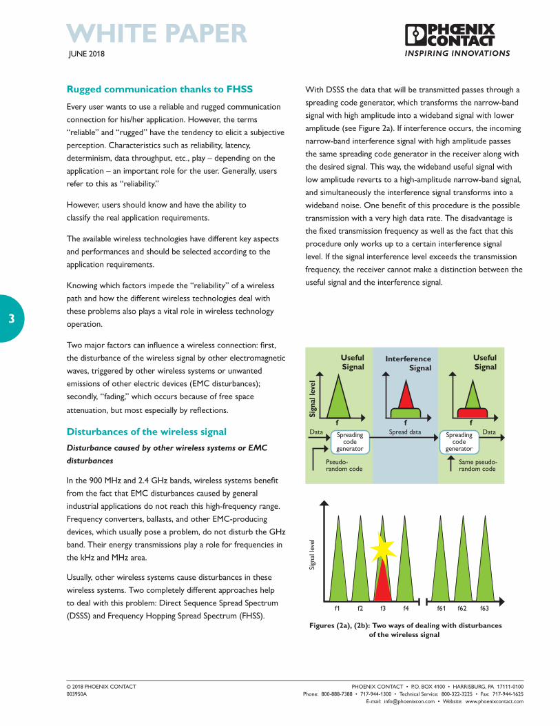
(DSSS) and Frequency Hopping Spread Spectrum (FHSS).
Figure 2: In a wastewater treatment facility, the treatment operator wants to know as much as possible about the pump’s state of health.
With DSSS the data that will be transmitted passes through a
spreading code generator, which transforms the narrow-band
signal with high amplitude into a wideband signal with lower
amplitude (see Figure 2a). If interference occurs, the incoming
narrow-band interference signal with high amplitude passes
the same spreading code generator in the receiver along with
the desired signal. This way, the wideband useful signal with
low amplitude reverts to a high-amplitude narrow-band signal,
and simultaneously the interference signal transforms into a
wideband noise. One benefit of this procedure is the possible
transmission with a very high data rate. The disadvantage is
the fixed transmission frequency as well as the fact that this
procedure only works up to a certain interference signal
level. If the signal interference level exceeds the transmission
frequency, the receiver cannot make a distinction between the
useful signal and the interference signal.
Sign
al le
vel
f f f
UsefulSignal
InterferenceSignal
UsefulSignal
Data Spreading code
generator
Pseudo-random code
Spread data Spreading code
generator
Data
Same pseudo-random code
Sign
al le
vel
f1 f2 f3 f4 f61 f62 f63
Figures (2a), (2b): Two ways of dealing with disturbances of the wireless signal
JUNE 2018
© 2018 PHOENIX CONTACT PHOENIX CONTACT • P.O. BOX 4100 • HARRISBURG, PA 17111-0100 003950A Phone: 800-888-7388 • 717-944-1300 • Technical Service: 800-322-3225 • Fax: 717-944-1625
E-mail: [email protected] • Website: www.phoenixcontact.com
4
With FHSS, many different individual frequencies or
channels are utilized in a pseudo-random pattern. This way,
an interference signal only blocks one or a few neighbored
individual frequencies – no matter how high the level – so
at least some portion of the communication continues.
If disturbances worsen, only the data throughput is
reduced in the FHSS system. In the DSSS system, however,
communication may be completely blocked.
Trusted Wireless 2.0 uses FHSS. The number of
frequencies used within the pseudo-random hopping
pattern depends
on further settings and mechanisms such as the exclusion
of certain frequency ranges (blacklisting)
for the coexistence management, or the use of
several frequency groups (RF bands) to optimize
the parallel operation.
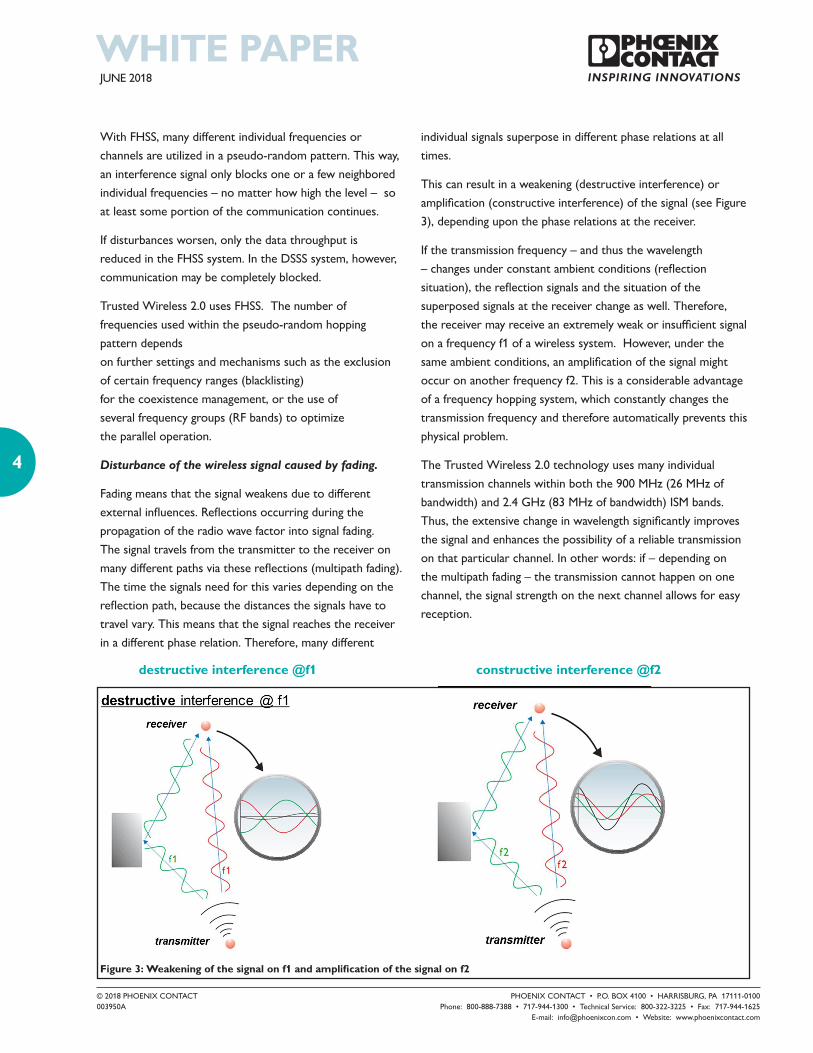
Disturbance of the wireless signal caused by fading.
Fading means that the signal weakens due to different
external influences. Reflections occurring during the
propagation of the radio wave factor into signal fading.
The signal travels from the transmitter to the receiver on
many different paths via these reflections (multipath fading).
The time the signals need for this varies depending on the
reflection path, because the distances the signals have to
travel vary. This means that the signal reaches the receiver
in a different phase relation. Therefore, many different
individual signals superpose in different phase relations at all
times.
This can result in a weakening (destructive interference) or
amplification (constructive interference) of the signal (see Figure
3), depending upon the phase relations at the receiver.
If the transmission frequency – and thus the wavelength
– changes under constant ambient conditions (reflection
situation), the reflection signals and the situation of the
superposed signals at the receiver change as well. Therefore,
the receiver may receive an extremely weak or insufficient signal
on a frequency f1 of a wireless system. However, under the
same ambient conditions, an amplification of the signal might
occur on another frequency f2. This is a considerable advantage
of a frequency hopping system, which constantly changes the
transmission frequency and therefore automatically prevents this
physical problem.
The Trusted Wireless 2.0 technology uses many individual
transmission channels within both the 900 MHz (26 MHz of
bandwidth) and 2.4 GHz (83 MHz of bandwidth) ISM bands.
Thus, the extensive change in wavelength significantly improves
the signal and enhances the possibility of a reliable transmission
on that particular channel. In other words: if – depending on
the multipath fading – the transmission cannot happen on one
channel, the signal strength on the next channel allows for easy
reception.
destructive interference @f1 constructive interference @f2
Figure 3: Weakening of the signal on f1 and amplification of the signal on f2

JUNE 2018
© 2018 PHOENIX CONTACT PHOENIX CONTACT • P.O. BOX 4100 • HARRISBURG, PA 17111-0100 003950A Phone: 800-888-7388 • 717-944-1300 • Technical Service: 800-322-3225 • Fax: 717-944-1625
E-mail: [email protected] • Website: www.phoenixcontact.com
5
Automatic and manual coexistence mechanisms
For many industrial applications, planning of the wireless
systems is recommended before deployment.
If a system requires several 802.11 WLAN networks, each
network should utilize different WLAN channels. WLAN
channels overlap; therefore, users should choose non-
sequential, non-overlapping channels for co-located systems,
e.g., channels 1, 6, and 11. If a 2.4 GHz Trusted Wireless
system is co-located with a WLAN network, the user
should blacklist the frequency ranges of the WLAN channel.
Similarly, in the 900 MHz band, if interference is detected
during the planning phase, a 900 MHz Trusted Wireless
system should blacklist those frequencies. With the
proliferation of wireless in industrial applications, users have
discovered an increasing importance in carefully planning the
frequency band used for the different systems and ensuring
the technology allows the blacklisting of frequency ranges.
Trusted Wireless 2.0 has the ability to blacklist frequency
ranges and therefore allows planning the coexistence with
other systems. For this, the system recalculates frequency
hopping patterns according to the blacklisted areas.
With Trusted Wireless 2.0, several aspects are incorporated
into the calculation of the frequency hopping patterns: firstly,
consideration of the blacklisted areas, secondly, the minimum
channel spacing to reach the biggest possible changes of
frequencies and wavelengths to compensate for multipath
fading.
The third aspect is the grouping of frequencies into “RF
bands.” An RF band consists of a group of channels spread
over the entire 900 MHz or 2.4 GHz band. Different RF
bands use completely different sets of channels. If two
wireless networks operate using two different RF bands in a
spatial environment, these two networks will never collide.
Secure communication thanks to encryption and authentication
Security plays an important role in the wireless transmission
technology. As information propagates through the
unprotected air, security strategies have to prevent
unauthorized access.
Anyone can access the widely used wireless technologies
Bluetooth and WLAN, which means that, in general, every
available wireless Bluetooth
or WLAN product allows a connection with a network. The
risk potential rises with WLAN, as it is commonly used in the
computer environment and attracts hacker activities.
The proprietary technology in Trusted Wireless 2.0, in
principle, has a much better protection system against possible
attacks. Moreover, the frequency hopping method makes spying
on the protocol much harder.
Additionally, Trusted Wireless 2.0 has two real security
mechanisms: the encryption of all transmitted information
according to the Advanced Encryption Standard (AES,) as well
as an authentication of the data in accordance with RFC 3610.
AES Encryption makes sure that hackers cannot extract the
content of theoretically captured data packets. A designated
password (Pre-Shared-Key) generates the 128-bit key and all
network devices must recognize this password.
The importance of the authentication of transmitted data
packets rates as highly as encryption. The simplest method
of attacking a wireless system: listen to a message, change it
and feed it back into the network. Therefore, the source of
the message must come from a guaranteed source, such as
an authenticated transmitter. For this, the messages have a
continuous code, which must not repeat. The code for Trusted
Wireless 2.0 was chosen in such a way that an attacker would
have to wait more than 1,000 years before the code repeats.
JUNE 2018
© 2018 PHOENIX CONTACT PHOENIX CONTACT • P.O. BOX 4100 • HARRISBURG, PA 17111-0100 003950A Phone: 800-888-7388 • 717-944-1300 • Technical Service: 800-322-3225 • Fax: 717-944-1625
E-mail: [email protected] • Website: www.phoenixcontact.com
6
Higher receiver sensitivity and adjustable data rates for increased range
For industrial wireless applications, the range plays a vital role,
especially for outdoor applications. Four key aspects of a radio
system determine range, and users can easily find them on any
data sheet: the operating frequency as discussed previously, the
transmitter power output, the receiver sensitivity, and the RF
data rate.
A regulating authority, such as the FCC, limits the transmitter
output power, and in practice, companies find it relatively
simple to design an RF transmitter that meets the regulatory
requirements. A radio device may have a transmitter power
level lower than the maximum allowable level for a purpose,
such as battery power options, or packaging and heating
restrictions.
Conversely, it is much more difficult to design a high-quality RF
receiver. The defining specification of a receiver is sensitivity,
which is a measure of the smallest (lowest) signal that the
receiver can “hear” and understand.
A more sensitive receiver can detect a lower signal, which
results in longer range. Designing a good receiver requires
careful selection of components such as a low noise amplifier
or “preamplifier” to boost the incoming signal, as well as good
filters to eliminate undesired interference.
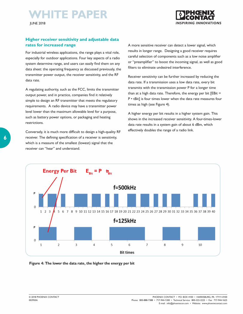
Receiver sensitivity can be further increased by reducing the
data rate. If a transmission uses a low data rate, every bit
transmits with the transmission power P for a longer time
than at a high data rate. Therefore, the energy per bit [EBit =
P • tBit] is four times lower when the data rate measures four
times as high (see Figure 4).
A higher energy per bit results in a higher system gain. This
shows in the increased receiver sensitivity. A four-times-lower
data rate results in a system gain of about 6 dBm, which
effectively doubles the range of a radio link.
Figure 4: The lower the data rate, the higher the energy per bit
Energy Per Bit EBit = P tBit

JUNE 2018
© 2018 PHOENIX CONTACT PHOENIX CONTACT • P.O. BOX 4100 • HARRISBURG, PA 17111-0100 003950A Phone: 800-888-7388 • 717-944-1300 • Technical Service: 800-322-3225 • Fax: 717-944-1625
E-mail: [email protected] • Website: www.phoenixcontact.com
7
Trusted Wireless 2.0 offers different, adjustable data rates.
Thus, depending on the application requirements, the range
can be many times longer than the ranges of common Blue-
tooth and WLAN systems.
In order to determine the link budget, the transmission power
must be added to the receiver sensitivity along with the
antenna gain, while subtracting coaxial cable attenuations.
A reliable wireless connection should also always operate with
a minimum system reserve or fade margin of 10-15 dB.
With Trusted Wireless 2.0 technology, wireless links
stretching over several miles/kilometers are possible,
depending on the data rate and antenna installation
used. When using the 2.4 GHz system, Phoenix Contact
recommends its use for applications less than 1 km, and using
the 900 MHz system for longer links.
Increased robustness and coexistence with superheterodyne radio design
Today, “industrial” radios utilize two basic types of
receiver designs.
A direct conversion receiver accepts the radio signal and then
directly processes it to extract the original data.
The simpler architecture of a direct conversion receiver
results in a lower-cost radio but sacrifices some performance,
especially in the critical aspect of noise rejection in relation to
harsh industrial environments. The ability of a radio receiver
to reject interference has a direct correlation to range,
coexistence with other radio systems, and throughput.
A superheterodyne radio receiver uses frequency mixing to
convert a received RF signal to a lower frequency, called an
intermediate frequency (IF), that is processed more easily
than the original signal. This provides opportunities for
additional stages of filtering and greatly improves selectivity, or
the receiver’s ability to select the desired signal from a noisy
environment. This also increases the receiver’s sensitivity, and
thus a superheterodyne receiver provides significantly improved
performance in industrial environments, although the increased
complexity of the design does impact the cost.
Today, the Trusted Wireless 2.0 protocol is used on a 2.4 GHz
direction conversion radio and a 900 MHz superheterodyne
radio platform.
Flexible networks with automatic connection management
As already mentioned, there are special requirements to ensure
the reliability of wireless networks in an industrial environment.
The right network structure can considerably improve this
reliability.
Bluetooth uses only point-to-point connections, and a master
can manage up to seven of them simultaneously. This way, up
to seven Bluetooth slaves can operate under one Bluetooth
master.
A WLAN access point works in a star structure with a
reasonable number of approximately 20 clients. Neither
3 miles
Up to 1 mile
Up to 20 miles
SUR
VE
YD
ESI
GN
1 mile
1,500 feet
300 feet
NO
WO
RRY
SURV
EYD
ESIG
N
Radioline 2.4 GHz
Radioline 900 MHz
ZONES
NO WORRY Network design not required
SURVEYSite testing recommended
DESIGNSystem integrator recommended
Figure 5: Radioline Zones of Success

JUNE 2018
© 2018 PHOENIX CONTACT PHOENIX CONTACT • P.O. BOX 4100 • HARRISBURG, PA 17111-0100 003950A Phone: 800-888-7388 • 717-944-1300 • Technical Service: 800-322-3225 • Fax: 717-944-1625
E-mail: [email protected] • Website: www.phoenixcontact.com
8
technology supports true repeater functionality, making network
expansions somewhat limited.
Trusted Wireless 2.0 has store-and-forward repeater
functionality and the network can heal itself if a link
breaks, i.e., build up/find an alternative connection path (self-
healing network).
This automatic self-healing implementation occurs within
milliseconds or seconds after losing a link, depending on the data
rate. Users sometimes refer to this self-healing capability as a
mesh network, although definitions of a mesh network vary.
A Trusted Wireless 2.0 wireless network can therefore operate
in all network formations
(see Figure 6)
Due to the high receiver sensitivity of Trusted Wireless 2.0,
sometimes a node does not connect to the nearest node but
to another one farther away. Due to this, Trusted Wireless
2.0 offers the possibility to do a parent-blacklisting. With this
method, users specifically exclude nodes from acting as possible
repeaters. For every node, the system can “forbid” other nodes
(parent-blacklisting) or “allow” (parent-white-listing) as repeaters.
By default, the system permits all repeaters as possible nodes.
This functionality enables network optimization and
network structures (e.g., a chain) to build up, if desired.
In figure 7, nodes 1, 2, or 3 might offer good connections
for node 5, while nodes 4, 6, and 9, which are not reliable,
should go into a parent-blacklisting.
Figure 6: Network
Figure 7: Parent-blacklisting for node 5 should
contain nodes 4, 6, and 9
Figure 8: Distributed network management in the
parent-child zone (P/C zone)

JUNE 2018
© 2018 PHOENIX CONTACT PHOENIX CONTACT • P.O. BOX 4100 • HARRISBURG, PA 17111-0100 003950A Phone: 800-888-7388 • 717-944-1300 • Technical Service: 800-322-3225 • Fax: 717-944-1625
E-mail: [email protected] • Website: www.phoenixcontact.com
9
Distributed network maintenance – faster and easier
In order to operate a wireless network – independent of the
data volume transmitted – individual wireless nodes must have
internal communication capabilities. In this context, the process
for adding a new node to the network (joining), as well as the
management of already existing nodes, plays an important role.
Wireless networks such as Zigbee or WirelessHART follow
a central approach and use a central control function called a
network manager or coordinator. This means that the manager
initiates all network management messages, which must move
through the network to the target nodes. Any acknowledgment
messages must also travel the entire way back to the manager.
This concept can cause higher message traffic.
Trusted Wireless 2.0, however, uses a patented, distributed
approach. Here, the implementation of the entire network
management occurs within the parent-child zone. This means
that a parent (either a master or repeater) takes care of its
children and, if necessary, also integrates new nodes into its
zone. This information does not have to transmit all the way
to the central manager and back, which in turn reduces the
message traffic in the network and considerably accelerates the
entire process.
This has a positive effect on the network formation speed. If,
in a centrally managed network, the
power supply for the manager fails
and it therefore loses the information
on the relation of the nodes, network
reformation could take a long time.
With Trusted Wireless 2.0, though,
these processes run in parallel in the
individual “branches,” or parent-child
zone, of the network tree (see Figure
8). This considerably accelerates the
reformation of the wireless network.
Extensive diagnostic properties
For industrial wireless network operations, the consequences
of non-availability far exceed those of private-sector, home
applications. Users wish to have greater access to network
information, and diagnostics provide the vital information that
users want on the state of their wireless networks.
Trusted Wireless 2.0 offers a wide range of diagnostic
information, such as network structure and channel statistics.
The node table contains information on the directly
connected nodes, their properties (master, repeater, slave)
their connection quality (RSSI signal), the network depth and
the list of permitted or prohibited parents.
The channel table contains information on the radio
frequencies used, for example, on the noise level (current and
maximum), the channel blocking rate and the packet error
rate.
Users can query all diagnostic information remotely and give
an exact overview of the network and its environment. This
also allows for targeted optimization measures.
Figure 9: Comparison of different wireless
technologies
JUNE 2018
© 2018 PHOENIX CONTACT PHOENIX CONTACT • P.O. BOX 4100 • HARRISBURG, PA 17111-0100 003950A Phone: 800-888-7388 • 717-944-1300 • Technical Service: 800-322-3225 • Fax: 717-944-1625
E-mail: [email protected] • Website: www.phoenixcontact.com
10
Adjustable to the desired application
Trusted Wireless 2.0, a wireless technology developed especially
for industrial use, was based on the requirements of industrial
infrastructure applications and closes the gap between specific sensor
networks such as WirelessHART and the high-speed technology
WLAN.
Characterized by its particularly good adaptability to the desired
industrial application, Trusted Wireless 2.0 offers a high degree of
reliability, ruggedness, security and flexibility.
Glossary
AES Advanced Encryption Standard
DSSS Direct Sequence Spread Spectrum
EMC Electromagnetic compatibility
FHSS Frequency Hopping Spread Spectrum
IEEE Institute of Electrical and Electronics
Engineers
ISM band Industrial Scientific Medical band
LBT Listen Before Talk
LOS Line of sight
NLOS Non-line-of-sight OTA Over-the-Air
P/C zone Parent-Child zone
R & TTE Radio and Telecommunications Terminal
Equipment
RF band Radio frequency band
RFC Request for Comments
RSSI Receive Signal Strength Indicator
WLAN Wireless Local Area Network
ABOUT PHOENIX CONTACT
Phoenix Contact develops and manufactures
industrial electrical and electronic technology
products that power, protect, connect, and
automate systems and equipment for a wide range
of industries. Phoenix Contact GmbH & Co. KG,
Blomberg, Germany, operates 50 international
subsidiaries, including Phoenix Contact USA in
Middletown, Pa.
For more information about Phoenix Contact or its
products, visit www.phoenixcontact.com, call technical service at 800-322-3225, or
e-mail [email protected].
Originally published Febuary 2014