ts 101 012 - v1.2.1 - transmission and multiplexing … · 7.3.5.1 atm virtual path non-intrusive...
TRANSCRIPT

ETSI TS 101 012 V1.2.1 (2001-09)
Technical Specification
Transmission and Multiplexing (TM);Broadband Access Digital Section
and NT functional requirements

ETSI
ETSI TS 101 012 V1.2.1 (2001-09)2
Reference RTS/TM-06015
Keywords access, architecture, ATM, B-ISDN, MUX,
network, SDH, transmission, UNI, V interface
ETSI
650 Route des Lucioles F-06921 Sophia Antipolis Cedex - FRANCE
Tel.: +33 4 92 94 42 00 Fax: +33 4 93 65 47 16
Siret N° 348 623 562 00017 - NAF 742 C
Association à but non lucratif enregistrée à la Sous-Préfecture de Grasse (06) N° 7803/88
Important notice
Individual copies of the present document can be downloaded from: http://www.etsi.org
The present document may be made available in more than one electronic version or in print. In any case of existing or perceived difference in contents between such versions, the reference version is the Portable Document Format (PDF).
In case of dispute, the reference shall be the printing on ETSI printers of the PDF version kept on a specific network drive within ETSI Secretariat.
Users of the present document should be aware that the document may be subject to revision or change of status. Information on the current status of this and other ETSI documents is available at
http://portal.etsi.org/tb/status/status.asp
If you find errors in the present document, send your comment to: [email protected]
Copyright Notification
No part may be reproduced except as authorized by written permission. The copyright and the foregoing restriction extend to reproduction in all media.
© European Telecommunications Standards Institute yyyy.
All rights reserved.

ETSI
ETSI TS 101 012 V1.2.1 (2001-09)3
Contents
Intellectual Property Rights ................................................................................................................................6
Foreword.............................................................................................................................................................6
1 Scope ........................................................................................................................................................7
2 References ................................................................................................................................................7
3 Definitions and abbreviations...................................................................................................................9 3.1 Definitions..........................................................................................................................................................9 3.2 Abbreviations ...................................................................................................................................................10
4 Reference configurations........................................................................................................................12 4.1 B-ADS supporting a single ATM interface at UNI ..........................................................................................12 4.1.1 Functions of xDSL based B-NT supporting a single ATM interface..........................................................13 4.2 B-ADS supporting multiple ATM UNIs ..........................................................................................................14 4.2.1 Functions of an xDSL based B-NT supporting multiple ATM UNIs .........................................................14 4.3 B-ADS supporting non ATM Interfaces ..........................................................................................................15 4.3.1 Functions of an xDSL based B-NT supporting non ATM interfaces..........................................................15
5 B-NT functional requirements................................................................................................................16 5.1 Transmission functions.....................................................................................................................................16 5.1.1 Requirements of xDSL bearer capabilities .................................................................................................16 5.1.1.1 ADSL transport capabilities ..................................................................................................................17 5.1.1.2 VDSL transport capabilities ..................................................................................................................17 5.1.1.3 SDSL transport capabilities...................................................................................................................17 5.1.2 Co-Existence with narrowband services .....................................................................................................17 5.1.2.1 Sharing of same physical medium by frequency separation .................................................................17 5.1.2.2 Sharing of the same transceiver ............................................................................................................17 5.1.3 OAM functions ...........................................................................................................................................17 5.2 ATM layer functions ........................................................................................................................................18 5.2.1 VP connectivity ..........................................................................................................................................19 5.2.2 VP trail termination ....................................................................................................................................20 5.2.3 VC connectivity ..........................................................................................................................................20 5.2.4 VC trail termination ....................................................................................................................................21 5.2.5 Support of dual latency ...............................................................................................................................21 5.2.6 Implications of rate adaptation....................................................................................................................21 5.2.7 Implications of rate repartitioning ..............................................................................................................22 5.2.8 UPC/NPC....................................................................................................................................................22 5.2.9 Traffic shaping............................................................................................................................................22 5.2.10 Congestion control......................................................................................................................................22 5.2.11 Operation and Maintenance (OAM) ...........................................................................................................23 5.2.11.1 AIS function..........................................................................................................................................23 5.2.11.2 Remote Defect Indication (RDI) function.............................................................................................23 5.2.11.3 Continuity check function .....................................................................................................................23 5.2.11.4 Loopback function ................................................................................................................................23 5.2.11.5 VP-AIS..................................................................................................................................................25 5.2.11.6 VP-RDI .................................................................................................................................................25 5.2.11.7 VP Continuity Check ............................................................................................................................25 5.2.11.8 VP-Loopback ........................................................................................................................................25 5.2.11.9 VC-AIS .................................................................................................................................................25 5.2.11.10 VC-RDI.................................................................................................................................................25 5.2.11.11 VC-Continuity Check............................................................................................................................26 5.2.11.12 VC-Loopback........................................................................................................................................26 5.3 Supported UNIs................................................................................................................................................26 5.3.1 ATM based UNIs........................................................................................................................................26 5.3.2 Non ATM User Network Interfaces............................................................................................................27 5.4 Interworking functions for the support of non ATM interfaces .......................................................................27 5.4.1 Support of Ethernet interfaces ....................................................................................................................27

ETSI
ETSI TS 101 012 V1.2.1 (2001-09)4
5.4.1.1 Bridging mode.......................................................................................................................................27 5.4.1.2 Routing mode........................................................................................................................................28 5.4.2 Support of USB interfaces ..........................................................................................................................28 5.5 B-NT Management Functions ..........................................................................................................................28 5.5.1 Management Architecture...........................................................................................................................28 5.5.2 Management Communication Channel.......................................................................................................29 5.5.3 Management Protocol .................................................................................................................................29 5.5.4 Management elements ................................................................................................................................30 5.5.5 Void ............................................................................................................................................................30 5.5.6 Management Information Base...................................................................................................................30 5.6 Local Signalling Functions...............................................................................................................................30 5.6.1 B-NT status.................................................................................................................................................30 5.6.2 Line status...................................................................................................................................................30 5.6.3 UNI Port status ...........................................................................................................................................30 5.7 Timing function................................................................................................................................................30 5.8 Local powering.................................................................................................................................................31 5.9 Activation/deactivation ....................................................................................................................................31 5.10 Atomic model of a B-NT supporting ATM UNIs ............................................................................................31
6 B-LT and B-TE Functional Requirements .............................................................................................32
7 Functional Model and Processes ............................................................................................................32 7.1 Introduction ......................................................................................................................................................32 7.2 Modelling of Transfer and Layer Management Functions ...............................................................................33 7.3 ATM Layer Functions ......................................................................................................................................34 7.3.1 ADSL TP to ATM VP Adapt. Source Function (ADSLtp/Avp_A_So) .....................................................34 7.3.2 ADSL TP Layer to ATM VP Adapt. Sink Funct. (ADSLtp/Avp_A_Sk) ...................................................35 7.3.3 ATM Virtual Path Connection Function (Avp_C)......................................................................................38 7.3.4 ATM virtual path Trail Termination functions (Avp_TT)..........................................................................40 7.3.4.1 ATM virtual path Trail Termination Source Avp_TT_So ....................................................................40 7.3.4.2 ATM Virtual Path Trail Termination Sink (Avp_TT_Sk) ....................................................................41 7.3.5 ATM Virtual Path Monitoring Functions ...................................................................................................43 7.3.5.1 ATM Virtual Path Non-intrusive Monitoring Function Avpm_TT_Sk ................................................43 7.3.6 ATM Virtual Path Segment Functions........................................................................................................45 7.3.7 ATM Virtual Path Traffic Management Functions.....................................................................................45 7.3.7.1 ATM VP Traffic Management Trail Termination Source function (AvpT_TT_So) ............................46 7.3.7.2 ATM Virtual Path Traffic Management Trail Termination Sink function (AvpT_TT_Sk) ..................47 7.3.7.3 ATM VP Traffic Management to ATM VP Adaptation Source function (AvpT/Avp_A_So) .............48 7.3.7.4 ATM VP Traffic Management to ATM VP Adapt. Sink function (AvpT/Avp_A_Sk)........................49 7.3.8 ATM Virtual Path Loopback Functions......................................................................................................50 7.3.8.1 ATM Virtual Path Loopback Source Function Avplb_TT_So .............................................................50 7.3.8.2 ATM Virtual Path Loopback Sink Function Avplb_TT_Sk .................................................................51 7.3.9 ATM Virtual Path to ATM Virtual Channel Adaptation Functions ...........................................................52 7.3.9.1 ATM Virtual Path to ATM Virtual Channel Adaptation Source Avp/Avc_A_So................................52 7.3.9.2 ATM Virtual Path to ATM Virtual Channel Adaptation Sink Avp/Avc_A_Sk....................................53 7.3.10 ATM Virtual Channel Connection Function Avc_C ..................................................................................55 7.3.11 ATM Virtual Channel Trail Termination Functions ...................................................................................57 7.3.11.1 ATM Virtual Channel Trail Termination Source (Avc_TT_So)...........................................................57 7.3.11.2 ATM Virtual Channel Trail Termination Sink (Avc_TT_Sk) ..............................................................58 7.3.12 ATM Virtual Channel Monitoring Functions .............................................................................................60 7.3.12.1 ATM Virtual Channel Non-intrusive Monitoring Function (Avpm_TT_Sk) .......................................60 7.3.13 ATM Virtual Channel Segment Functions .................................................................................................62 7.3.13.1 ATM Virtual Channel Segment Trail Termination Source function (AvcS_TT_So) ...........................62 7.3.13.2 ATM Virtual Channel Segment Trail Termination Sink function (AvcS_TT_Sk) ...............................63 7.3.13.3 ATM VC Segment to ATM VC Adapt. Source function (AvcS/Avc_A_So).......................................64 7.3.13.4 ATM VC Segment to ATM VC Adaptation Sink function (AvcS/Avc_A_Sk)....................................65 7.3.14 ATM Virtual Channel Traffic Management Functions ..............................................................................66 7.3.14.1 ATM VC Traffic Management Trail Termination Source function (AvcT_TT_So) ............................66 7.3.14.2 ATM VC Traffic Management Trail Termination Sink function (AvcT_TT_Sk) ................................67 7.3.14.3 ATM VC Traffic Management to ATM VC Adapt. Source function (AvcT/Avc_A_So)....................68 7.3.14.4 ATM VC Traffic Management to ATM VC Adapt. Sink function (AvcT/Avc_A_Sk) .......................69 7.3.15 ATM Virtual Channel Loopback Functions ...............................................................................................70

ETSI
ETSI TS 101 012 V1.2.1 (2001-09)5
7.3.15.1 ATM Virtual Channel Loopback Source Function (Avclb_TT_So).....................................................70 7.3.15.2 ATM Virtual Path Loopback Sink Function Avclb_TT_Sk .................................................................71 7.3.16 ATM Virtual Channel to ATM Client Adaptation Functions .....................................................................72 7.3.16.1 ATM Virtual Channel to ATM Client Adaptation Source Avc/XXX_A_So........................................72 7.3.16.2 ATM Virtual Channel to ATM Client Adaptation Sink Avc/XXX_A_Sk ...........................................73 7.4 xDSL Transmission Functions .........................................................................................................................74 7.4.1 ADSL..........................................................................................................................................................74 7.4.1.1 ADSL PMD layer functions..................................................................................................................74 7.4.1.2 ADSL PMD Layer Trail Termination Source Function (ADSLpmd _TT_So).....................................75 7.4.1.3 ADSL PMD Layer Trail Termination Sink Function ADSLpmd _TT_Sk ...........................................76 7.4.1.4 ADSL PMD Layer to Section Adaptation Source Function (ADSLpmd/s_A_So)...............................77 7.4.1.5 ADSL PMD Layer to Section Adaptation Sink Function ADSLpmd/s_A_Sk .....................................78 7.4.1.6 ADSL Section Layer Functions ............................................................................................................79 7.4.1.7 ADSL Section Layer Trail Termination Source Function ADSLs_TT_So...........................................79 7.4.1.8 ADSL Section Layer Trail Termination Sink Function ADSLs_TT_Sk ..............................................82 7.4.1.9 ADSL Section Layer to TP Adaptation Source Function ADSLs/tp _A_So ........................................85 7.4.1.10 ADSL Section Layer to TP Adaptation Sink Function ADSLs/tp_A_Sk .............................................86 7.4.1.11 ADSL TP Layer Functions....................................................................................................................87 7.4.1.12 ADSL TP Layer Connection Function ADSLtp _C..............................................................................87 7.4.1.13 ADSL TP Layer Trail Termination Source Function ADSLtp _TT_So ...............................................88 7.4.1.14 ADSL TP Layer Trail Termination Sink Function ADSLtp _TT_Sk ...................................................89 7.4.2 VDSL..........................................................................................................................................................89 7.4.3 SDSL ..........................................................................................................................................................89 7.5 ATM25,6 UNI Transmission Functions...........................................................................................................90 7.5.1 ATM25,6 PMD Layer Functions ................................................................................................................90 7.5.1.1 ATM25,6 PMD Layer Trail Termination Source Function (ATM25pmd _TT_So) .............................90 7.5.1.2 ATM25,6 PMD Layer Trail Termination Sink Function (ATM25pmd _TT_Sk).................................91 7.5.1.3 ATM25,6 PMD Layer to Section Adapt. Source Function (ATM25pmd/s _A_So) .............................92 7.5.1.4 ATM25,6 PMD Layer to Section Adapt. Sink Function (ATM25pmd/s _A_Sk).................................92 7.5.2 ATM25,6 Section Layer Functions.............................................................................................................93 7.5.2.1 ATM25,6 Section Layer Trail Termination Source Function (ATM25s _TT_So) ...............................94 7.5.2.2 ATM25,6 Section Layer Trail Termination Sink Function (ATM25s _TT_Sk)...................................94 7.5.2.3 ATM25,6 Section Layer to TP Adaptation Source Function (ATM25s/tp _A_So) ..............................95 7.5.2.4 ATM25,6 Section Layer to TP Adaptation Sink Function (ATM25s/tp _A_Sk)..................................96 7.5.3 ATM25,6 Transmission Path Layer Functions ...........................................................................................96 7.5.3.1 ATM25,6 TP Layer Trail Termination Source Function (ATM25tp _TT_So).....................................97 7.5.3.2 ATM25,6 TP Layer Trail Termination Sink Function (ATM25tp _TT_Sk).........................................98 7.5.3.3 ATM25,6 TP Layer to ATM V. P. Adapt. Source Function ATM25tp/Avp_A_So .............................99 7.5.3.4 ATM25,6 TP Layer to ATM V. P. Adapt. Sink Function (ATM25tp/Avp_A_Sk) ............................100 7.6 Terminal Adapter Functions...........................................................................................................................101 7.7 Modelling of Equipment Management Functions ..........................................................................................101
Annex A (informative): Techniques of POTS/ISDN support ...........................................................102
A.1 Spectral parameters of BA ISDN and ADSL signals.............................................................................102
A.2 Two mode ADSL system in access network architecture .....................................................................105
Annex B (informative): Bibliography.................................................................................................107
History ............................................................................................................................................................108

ETSI
ETSI TS 101 012 V1.2.1 (2001-09)6
Intellectual Property Rights IPRs essential or potentially essential to the present document may have been declared to ETSI. The information pertaining to these essential IPRs, if any, is publicly available for ETSI members and non-members, and can be found in ETSI SR 000 314: "Intellectual Property Rights (IPRs); Essential, or potentially Essential, IPRs notified to ETSI in respect of ETSI standards", which is available from the ETSI Secretariat. Latest updates are available on the ETSI Web server (http://www.etsi.org/legal/home.htm).
Pursuant to the ETSI IPR Policy, no investigation, including IPR searches, has been carried out by ETSI. No guarantee can be given as to the existence of other IPRs not referenced in ETSI SR 000 314 (or the updates on the ETSI Web server) which are, or may be, or may become, essential to the present document.
Foreword This Technical Specification (TS) has been produced by ETSI Technical Committee Transmission and Multiplexing (TM).

ETSI
ETSI TS 101 012 V1.2.1 (2001-09)7
1 Scope The present document defines the functional requirements for an "ATM over xDSL" Broadband Access Digital Section (ADS), between the UNI interface at T/S reference point and the Access Network End System at the VB1 reference point, operated over an xDSL connection between an xDSL based Broadband Network Termination and an xDSL based Broadband Line Termination, both these elements being essential constituents of the B-ADS.
The definition of B-ADS functional characteristics and protocols should enable proper interworking of the B-NT with:
a) the Customer Premises Network (B-NT2 or TE) on the customer side;
b) the B-LT and more generally the Access Network End System on the other side,
for the provision of ATM connectivity.
At the same time, the specified operational and management requirements will enable proper interworking of the B-ADS elements with the remaining Access Network elements and with the Service Node, as well as proper B-ADS management.
The present document also identifies proper protocols and relevant supporting facilities for the control and management of the Customer Premises Network.
2 References The following documents contain provisions which, through reference in this text, constitute provisions of the present document.
• References are either specific (identified by date of publication and/or edition number or version number) or non-specific.
• For a specific reference, subsequent revisions do not apply.
• For a non-specific reference, the latest version applies.
[1] ITU-T Recommendation G.967.2: "VB5.2 reference point specification".
[2] ITU-T Recommendation G.967.1: "VB5.1 reference point specification".
[3] ATM Forum Specification af-sig-0061.000 (v4.0): "User-NetworkInterface Signalling Secification".
[4] ATM Forum Specification af-ilmi-0065.000 (v4.0, 1996): "ILMI (Integrated Local Management Interface)".
[5] ATM Forum af-rbb-phy-0101.000: "Residential Broadband Physical Interfaces Specification".
[6] ATM Forum af-phy-0040.000 (1995): "Physical Interface Specification for 25,6 Mbit/s over Twisted Pair Cable".
[7] ATM Forum af-phy-0018.000 (1994) (VDSL 51/1.6 Mbit/s): "Mid-range Physical Layer Specification for Category 3 Unshielded Twisted-Pair".
[8] IETF RFC 2684: "Multiprotocol Encapsulation over ATM Adaptation Layer 5".
[9] IETF RFC 2225: "Classical IP and ARP over ATM".
[10] USB Implementers Forum: "Universal Serial Bus v1.1 (USB)". http://www.usb.org/developers/docs.html.
[11] IETF RFC 1157: "Simple Network Management Protocol (SNMP)".

ETSI
ETSI TS 101 012 V1.2.1 (2001-09)8
[12] IEEE 802.3: "IEEE Standard for Information technology-Local and metropolitan area networks-Part 3: Carrier sense multiple access with collision detection (CSMA/CD) access method and physical layer specifications".
[13] ETSI ETS 300 404 (1999): "Broadband Integrated Services Digital Network (B-ISDN); B-ISDN Operation And Maintenance (OAM) principles and functions".
[14] ITU-T Recommendation I.113: "Vocabulary of terms for broadband aspects of ISDN".
[15] ITU-T Recommendation G.992.1: "Asymmetric digital subscriber line (ADSL) Transceivers".
[16] ITU-T Recommendation G.994.1: "Handshake procedures for digital subscriber line (DSL) Transceivers".
[17] ITU-T Recommendation G.997.1: "Physical layer Management for digital subscriber line (DSL) Transceivers".
[18] ETSI EN 301 163-2-1: "Transmission and Multiplexing (TM); Generic requirements of Asynchronous Transfer Mode (ATM) transport functionality within equipment; Part 2-1: Functional model for the transfer and layer management plane".
[19] ETSI ETS 300 301 (1996): "Broadband Integrated Services Digital Network (B-ISDN); Traffic control and congestion control in B-ISDN [ITU-T Recommendation I.371 (1996)]".
[20] ETSI ETS 300 298-2 (1999): "Broadband Integrated Services Digital Network (B-ISDN); Asynchronous Transfer Mode (ATM); Part 2: B-ISDN ATM layer specification [ITU-T Recommendation I.361 (1995)]".
[21] ITU-T Recommendation I.732: "Functional characteristics of ATM equipment".
[22] ITU-T Recommendation I.733: "Voice cell assembly/disassembly compression equipment".
[23] ETSI TS 101 524: "Transmission and Multiplexing (TM); Access transmission system on metallic access cables; Symmetrical single pair high bitrate Digital Subscriber Line (SDSL)".
[24] ETSI TS 101 270: "Transmission and Multiplexing (TM); Access transmission systems on metallic access cables; Very high speed Digital Subscriber Line (VDSL)".
[25] ETSI ETS 300 417-1-1: "Transmission and Multiplexing (TM); Generic requirements of transport functionality of equipment; Part 1-1: Generic processes and performance".
[26] IETF RFC 2516: "A Method for Transmitting PPP Over Ethernet (PPPoE)".
[27] IEC 60664: "Insulation coordination for equipment within low-voltage systems".
[28] EN 61000-4-5: "Electromagnetic compatibility (EMC) - Part 4-5: Testing and measurement techniques - Surge immunity test".
[29] EN 61000-4-4: "Electromagnetic compatibility (EMC) - Part 4-4: Testing and measurement techniques - Electrical fast transient/burst immunity test".
[30] EN 61000-4-2: "Electromagnetic compatibility (EMC) - Part 4-2: Testing and measurement techniques - Electrostatic discharge immunity test".
[31] EN 60950: "Safety of information technology equipment".
[32] ETSI TS 102 080: "Transmission and Multiplexing (TM); Integrated Services Digital Network (ISDN) basic rate access; Digital transmission system on metallic local lines".
[33] ETSI TS 101 388: "Transmission and Multiplexing (TM); Access transmission systems on metallic access cables; Asymetric Digital Subscriber Line (ADSL) - Coexistence of ADSL and ISDN-BA on the same pair [ANSI T1.413 - 1998, modified]".

ETSI
ETSI TS 101 012 V1.2.1 (2001-09)9
3 Definitions and abbreviations
3.1 Definitions service node: identifies the network element including service related functionalities
NOTE 1: Service related functionalities are those functions which involve knowledge of user service profiles (e.g. signalling, IP address assignment).
access distribution network: corresponds to the transport network between the AN End System and the Service Node: the transport network does not include ATM functions
NOTE 2: In the simpler architectures the Access Distribution Network is not present.
broadband access digital section: consists of:
• the set of ATM Virtual Path or Virtual Channel connections between the B-UNI at TB reference point and the Access Network End System at VB1 reference point, for the support of the user traffic;
• the physical layer facilities (channels, protocols and relevant termination functions) for the management and control of NT physical layer, represented on the line side by xDSL functions;
• the set of ATM based channels, protocols and relevant termination functions for the overall NT control and management;
• the set of ATM based channels, protocols and relevant termination functions for the CPN control and management.
NOTE 3: For all these information flows relevant characteristics (such as minimum required channel bandwidth) and transfer modes are defined when required.
access network end system: last active network element before the Broadband Network Termination, going from the Service Node toward the Customer Premises Networks
NOTE 4: It includes the network side B-ADS termination functions, consisting of:
- ATM LT functions for the user traffic;
- xDSL physical layer (ATU-C or LT) functions;
- termination of B-NT management and control protocols;
- provision of the required synchronization flows (timing references).
As the CPN management and control protocols are terminated in the CPN (service) management system, the ANES must provide the required transport capability for these protocols.
It also includes the termination of proper control protocols for coordination with the Service Node: such protocols consist of those defined in [1], or [2], or alternatively those defined in [4].
broadband line termination: consists of the set of ATM and physical layer functions dedicated to the support of a single xDSL based access line within the Access Network End System
NOTE 5: The B-LT is delimited on the line side by the physical xDSL interface, and on the network side by the VB1 reference point.
broadband network termination: last network unit managed and controlled by the network operator

ETSI
ETSI TS 101 012 V1.2.1 (2001-09)10
NOTE 6: It consists of the following functions and information flows, some of which depend on the UNI(s) to be supported:
- xDSL physical layer termination;
- B-NT management and control protocols and relevant terminations;
- proper ATM VP or VC cross-connect functions for the support of the user traffic and CPN control and management protocols;
- proper termination functions for the support of ATM and non-ATM User Network Interfaces;
- proper support of visual indicators for local signalling of alarm/fault conditions;
- proper network synchronization;
- local powering.
customer premises network: customer internal network
NOTE 7: The CPN can incorporate more than one B-TE and more than one non-ATM TE. The B-NT is not part of the CPN but interfaces to it through the UNI interface. In the simplest case, the CPN is just a single TE or B-TE. Throughout the present document, where the architecture of the CPN is not relevant, the terms CPN and B-TE/TE may be used interchangeably.
broadband terminal equipment (b-te): any customer owned equipment provided with an ATM interface for the interconnection with the xDSL NT (or the Access Network End System directly), therefore it may include e.g. ATM switch or IP router
terminal equipment: any other customer equipment provided with a non-ATM interface for the interconnection with the xDSL NT
VB1 reference point: corresponds, as far as concerns the user traffic and the relevant OAM flows, to the functional interface between the ATM layer functions (including termination of proper OAM flows) specifically dedicated to the user traffic supported over a single xDSL line, and the other functions of the Access Network End System
NOTE 8: It also identifies the network side interface at which the termination functions for the B-ADS information flows are specified.
xDSL: generic term for the family of DSL technologies, including ADSL, HDSL, VDSL, SDSL
3.2 Abbreviations AAL ATM Adaptation Layer ADS Access Digital Section ADSL Asymmetrical Digital Subscriber Line AIS Alarm Indicating Signal AN Acces Network ANES Access Network End System ATM Abstract Test Method ATU-C ADSL Transceiver Unit - Central B-ADS Broadband Access Digital Section B-LT Broadband Line Termination B-NT Broadband Network Termination BRPM Backward Reporting Performance Monitoring B-TE Broadband Terminal Equipment CBDS Connectionless Broadband Data Service CC Continuity Check CCAD CC activation/deactivation CI Characteristic Information CLP Cell Loss Priority CNGI CoNGestion Indication CP Connection Point CPCS Common Part Convergence Sublayer

ETSI
ETSI TS 101 012 V1.2.1 (2001-09)11
CPID Connection Point Identifier CPN Customer Premises Network DSL Digital Subscriber Line DSLAM Digital Subscriber Line Access Multiplexer EC Echo Cancelled EFCI Explicit Forward Congestion Indication EMF Error Management Function FEC Forward Error Check FFT Fast Fourier Transform GFC General Flow Control HDLC High Level Data Link Control HDSL High bit rate Digital Subscriber Line HEC Header Errr Check IFFT Inverse Fast Fourier Transform INI Inter-Network Interface ISDN Integrated Services Digital Network IWU InterWorking Unit LAN Local Area Network LLC Logical Link Control LLID Loopback Location Identifier LOF Loss Of Frame LOS Loss Of Signal MIB Management Information Base MUX MUltipleXer NE Network Element NPC Network Protocol Control OAM Operation And Maintenance OUI Organizationnaly Unique Identifier PAD PADding PDH Plesiochronous Digital Hierarchy PDU Payload Data Unit PHY PHYsical layer termination function PID Protocol IDentifier POTS Plain Old Telephone Service PPPoE Point-to-Point Protocol over Ethernet PRNG Pseudo-Random Number Generator PSD Power Spectral Density PSTN Public Switched Telephone Network PTI Packet Type Identifier QoS Quality of Service RA Rate Adaptation RDI Remote Defect Indication RR Rate Repartitioning SDH Synchronous Digital Hierarchy SDSL Symmetrical single pair high bitrate Digital Subscriber Line SN Subscriber Number SNAP Sub-Network Attachement Point SNC System Network Controller SNI Secure Network Interface SNMP Simple Network Management Protocol SSF Server Signal Fail TCP Termination Connection Point TE Terminal Equipment TP Transport protocol UNI User Network Interface UPC Usage Parameter Control VAME Voice on ATM Multiplication Equipment VBR Variable Bit Rate VC Virtual Circuit VCC Virtual Channel Connection VCI Virtual Channel Identifier VDSL Very High Data Digital Subscriber Line

ETSI
ETSI TS 101 012 V1.2.1 (2001-09)12
VoIP Voice over Internet Protocol VP Virtual Path VPC Virtual Path Connection VPI Virtual Path Identifier xDSL x Digital Subscriber Line xTU-R xDSL Transceiver (user side)
4 Reference configurations
4.1 B-ADS supporting a single ATM interface at UNI The Broadband Access Digital Section supporting a single physical ATM interface at User Network Interface is shown in figure 1. The B-TE represents any customer equipment provided with ATM UNI interfaces.
B-TE
ACCESSDISTRIBUTION
NETWORK
(xDSL based)
B-NT
ACCESS NETWORKEND SYSTEM
S / TB B
UNI
(xDSL based)B-LT
SNIACCESS NETWORK
QAN
VB1
SN
BROADBAND ACCESS DIGITAL SECTION
SNI’
Figure 1: xDSL based ATM Access Digital Section supporting a single ATM interface at UNI
In this configuration the B-NT supports a single ATM based UNI interface, whose characteristics are compliant with the specifications given in the following clauses.
The CPN control channel is based on a single ATM signalling channel, supported over a virtual channel with the standard VPI and VCI value (0 and 5 respectively).

ETSI
ETSI TS 101 012 V1.2.1 (2001-09)13
4.1.1 Functions of xDSL based B-NT supporting a single ATM interface
The functional block diagram of an xDSL based B-NT, part of an ADS as identified in figure 1, and supporting a single ATM interface at the UNI, is shown in figure 2.
Management & Control Entity
T-R
SB = TB
ATMVP/VC
XC
P
Inter-Leaved
Fast
UNITerm.
Layer Management & Control
UNI
TC-I
B-TE
TC -F
xTU-R
Policing(UsageParameterControl)
Management & Control Coordination
P
Figure 2: Functions of xDSL based B-NT with single ATM interface at User Network Interface
The xTU-R and the ATM layer functions, represented by the ATM VP/VC Cross-Connect block, are described in detail in dedicated clauses of the present document.
NOTE: Some xDSL technologies do not support dual latency.
The ATM functions include the Usage Parameter Control (Policing) function at VP and possibly VC layer, to be operated on the traffic coming from the user and directed toward the network (upstream traffic).
No traffic shaping functions are performed in the B-NT on the downstream traffic, while ordinary buffering and multiplexing functions are performed in accordance with the general ATM principles; however the detailed specification of B-NT ATM and physical layer termination functions are specified in dedicated clauses of the present document.
The Management and Control Entity block includes the B-NT Management and Control protocol termination and local management functions: their detailed description is given in a dedicated clause of the present document.
The UNI Termination function is relevant to the Physical Layer functions for the ATM interface between the B-NT and the Broadband Terminal Equipment.
ATM interfaces taken into consideration are the following:
• 25 Mbit/s interface, as specified in [3];
• 51 Mbit/s interface, as specified in [7].

ETSI
ETSI TS 101 012 V1.2.1 (2001-09)14
4.2 B-ADS supporting multiple ATM UNIs The reference configuration for a B-ADS supporting multiple physical ATM interfaces at the User Network Interface is shown in figure 3. Each of these interfaces shall be provided with separate standard signalling (and optionally metasignalling) channels supported over VC connections with standard VPI/VCI values.
B-TE
ACCESSDISTRIBUTION
NETWORK
(xDSL based)
B-NT
ACCESS NETWORKEND SYSTEM
S = TB B
UNI
(xDSL based)B-LT
SNIACCESS NETWORK
QAN
VB1
SN
BROADBAND ACCESS DIGITAL SECTION
SNI’
Figure 3: xDSL based ATM Access Digital Section supporting multiple ATM interfaces at UNI
4.2.1 Functions of an xDSL based B-NT supporting multiple ATM UNIs
The functional block diagram of an xDSL based B-NT, part of a B-ADS as identified in figure 3, and supporting multiple ATM interfaces at User Network Interface, is shown in figure 4.
P
T-RxTU-R
SB = TB
ATMVP/VC
XC
P
Inter-Leaved
Fast
UNITerm.
UNITerm.
P TC-I
B-TE
TC -
Policing(UsageParameterControl)
Management & Control Entity
Layer Management & ControlManagement & Control Coordination
Figure 4: Functions of xDSL based B-NT with multiple ATM User Network Interfaces
The functions included in this B-NT are the same as those included in the B-NT supporting a single ATM UNI, the only difference being represented by the number of UNI Termination blocks and the corresponding number of interfaces between the UNI Termination block and the ATM VP/VC XC functional block.
Management and control functions for this type of B-NT are exactly the same used for the previous type of B-NT, the only difference being represented by a larger number of parameters to be managed or controlled.
The supported types of ATM interfaces are as described in clause 4.2.
ETSI
ETSI TS 101 012 V1.2.1 (2001-09)15
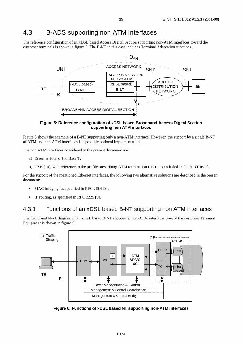
4.3 B-ADS supporting non ATM Interfaces The reference configuration of an xDSL based Access Digital Section supporting non-ATM interfaces toward the customer terminals is shown in figure 5. The B-NT in this case includes Terminal Adaptation functions.
TE
ACCESSDISTRIBUTION
NETWORK
(xDSL based)
B-NT
ACCESS NETWORKEND SYSTEM
R
UNI
(xDSL based)
B-LT
SNIACCESS NETWORK
QAN
VB1
SN
BROADBAND ACCESS DIGITAL SECTION
SNI’
Figure 5: Reference configuration of xDSL based Broadband Access Digital Section supporting non ATM interfaces
Figure 5 shows the example of a B-NT supporting only a non-ATM interface. However, the support by a single B-NT of ATM and non-ATM interfaces is a possible optional implementation.
The non ATM interfaces considered in the present document are:
a) Ethernet 10 and 100 Base T;
b) USB [10], with reference to the profile prescribing ATM termination functions included in the B-NT itself.
For the support of the mentioned Ethernet interfaces, the following two alternative solutions are described in the present document:
• MAC bridging, as specified in RFC 2684 [8];
• IP routing, as specified in RFC 2225 [9].
4.3.1 Functions of an xDSL based B-NT supporting non ATM interfaces
The functional block diagram of an xDSL based B-NT supporting non-ATM interfaces toward the customer Terminal Equipment is shown in figure 6.
ST-R
ATU-R
R
ATMVP/VC
XCInter-
Leaved
Fast
PHY
TC-I
TE
TC -
TrafficShaping
Management & Control Entity
Layer Management & Control Management & Control Coordination
IWUS
Figure 6: Functions of xDSL based NT supporting non-ATM interfaces

ETSI
ETSI TS 101 012 V1.2.1 (2001-09)16
The Terminal Adaptation functions are represented by the IWU functional block, which includes:
• ATM Termination;
• Traffic Shaping for the upstream generated ATM traffic;
• ATM Adaptation Layer Termination functions;
• Non-ATM functions.
The PHY block includes proper Physical Layer termination functions for the non-ATM interface.
5 B-NT functional requirements
5.1 Transmission functions
5.1.1 Requirements of xDSL bearer capabilities
The xDSL bearer requirements for transmission systems to be applied as part of broadband access digital sections can be identified by defining the server characteristics of physical layer for ATM layer and higher layers. From this point of view the following parameters have to be determined for every individual xDSL transmission system:
- number of concurrent transmission channels per direction of transmission;
- aggregate bandwidth available for higher layers per direction of transmission;
- specific data rate per particular transmission channel;
- data rate granularity;
- data rate symmetry between downstream/upstream direction;
- dynamic adjustment of aggregate data rate according to modified environmental conditions;
- dynamic re-partitioning of bandwidth between particular channels;
- transmission delay;
- transmission quality based on bit error rate;
- maximum interruption time of the transmission due to internal re-configurations (e.g. dynamic rate adaptation or dynamic rate re-partitioning);
- capabilities to transfer a reference clock of higher layers in downstream direction.
For the assessment of transmission technologies and implemented systems regarding to their application within access digital section the following minimum requirements shall be met:
General Requirements:
- at least one transmission channel per direction of transmission;
- the long term average maximum bit error rate shall not exceed 10-7 (because ATM and AAL do not always provide an error correction mechanism for the payload).
Service Specific Requirements:
- ratio between downstream and upstream rate not lower than or equal to 8 : 1 (if IP oriented services are supported);
- requirements about one-way delay due to the B-ADS will have to be defined accordingly to the specific services and corresponding network reference scenarios.

ETSI
ETSI TS 101 012 V1.2.1 (2001-09)17
NOTE: Though a minimum data rate of 2 Mbit/s in at least one direction of transmission is requested in other standard documents for broadband transmission systems (e.g. ITU-T Recommendation I.113 [14]) this requirement was not decided to be appropriate for xDSL systems operating with lower data rates. Furthermore it does not reflect the actual service-oriented demand of residential or small business customers.
5.1.1.1 ADSL transport capabilities
Transport capabilities for ADSL technology are described in [15].
5.1.1.2 VDSL transport capabilities
Transport capabilities for VDSL technology are described in [24].
5.1.1.3 SDSL transport capabilities
Transport capabilities for SDSL technology are described in [23].
5.1.2 Co-Existence with narrowband services
5.1.2.1 Sharing of same physical medium by frequency separation
Some types of xDSL transmission systems are capable of transferring narrowband services like POTS or ISDN simultaneously with the broadband signals over the same copper pair, by frequency separation. This combination is limited on the physical media level and therefore the requirements are outside the scope of Broadband Access Digital Section.
5.1.2.2 Sharing of the same transceiver
Another alternative is to transfer broadband and narrowband services as different bearers over the same xDSL transceiver. Refer to annex A, which outlines possible options and relevant consequences.
5.1.3 OAM functions
This clause provides an overview about physical layer Operation and Maintenance functions related to the OAM flows F1, F2 and F3 according to [13], adapted to xDSL transmission systems. Only those functions which are mandatory within the scope of B-NT are listed here.
Refer to the description of xDSL atomic functions in clause 7 for more detailed information about these OAM primitives.
ADSL specific OAM functions with their respective OAM primitives.
(Reference: ITU-T Recommendation G.992.1 [15]):
• Near End Fault Monitoring Function:
- Loss-Of-Signal defect (LOS);
- Severely Errored Frame defect (SEF);
- Loss of Cell Delineation Interleaved defect (LCD-I);
- Loss of Cell Delineation Fast defect (LCD-F);
- Loss of Power Defect (LPR).

ETSI
ETSI TS 101 012 V1.2.1 (2001-09)18
• Fault Reporting Function to Far End:
- Loss Of Signal indicator (LOS);
- Remote Defect Indication indicator (RDI);
- Loss of Power (Dying Gasp indicator).
• Near End Performance Monitoring Function:
- Forward Error Correction Interleaved anomaly (FEC-I);
- Forward Error Correction Fast anomaly (FEC-F);
- Cyclic Redundancy Check Interleaved anomaly (CRC-I);
- Cyclic Redundancy Check Fast anomaly (CRC-F);
- No Cell Delineation Interleaved anomaly (NCD-I);
- No Cell Delineation Fast anomaly (NCD-F);
- Out of Cell Delineation Interleaved anomaly (OCD-I);
- Out of Cell Delineation Fast anomaly (OCD-F);
- Header Error Check Interleaved anomaly (HEC-I);
- Header Error Check Fast anomaly (HEC-F).
• Performance Reporting Function to Far End:
- Forward Error Correction Count Interleaved data indicator (FECC-I);
- Forward Error Correction Count Fast data indicator (FECC-F);
- Far-End Block Error count Interleaved data indicator (FEBE-I);
- Far-End Block Error count Fast data indicator (FEBE-F);
- No Cell Delineation Interleaved data indicator (NCD-I);
- No Cell Delineation Fast data indicator (NCD-F);
- Header Error Check Interleaved data indicator (HEC-I);
- Header Error Check Fast data indicator (HEC-F).
5.2 ATM layer functions Figure 7 shows an overview about all possible atomic functions of a B-NT. The set of functions required for representing a pure VP Cross-Connect, a VC-Cross-Connect and a Terminal Adapter for non-ATM user interfaces is illustrated by the respective arrows.
NOTE: Make the figure more consistent with the table, e.g. immediate connection between different VP-CPs at user side.

ETSI
ETSI TS 101 012 V1.2.1 (2001-09)19
Avp_TT
Tp/Avp_A
VP_CP
Tp/Avp_A
Avc_TT
VC_TCP
Avp/Avc_AAvp/Avc_A
VC_CP
Avp_TTVP_TCP
1..2 xDSL TP(Latencychannels)
0..iATM user
ports
0..jnon ATMuser ports
Internal channels(e.g.
management)
VP-CrossConnect
VC-CrossConnect
TerminalAdapter
UserSide
AccessNetwork
Side
Avc/HL_A
VC_CP
Avc_TT
VC_TCP
Avc/HL_A
VC_CP
VC_CP
VP_TCP
Avp_C
VP_CP
Avc_C
Figure 7: Overview about B-NT ATM layer functions
5.2.1 VP connectivity
ATM Virtual Path Connections are identified for the following configuration cases:
a) connection of VP Connection Points (VP-CP) between user side and access network side (B-NT is representing a VP Cross Connect);
b) immediate connection between different VP-CPs at user side (B-NT is representing a VP Cross Connect);
c) connection of VP-CP and VP termination connection points (VP-TCP) at user side (B-NT is representing a VC Cross Connect);
d) connection of VP-CP and VP-TCP at access network side (B-NT is representing a VC Cross Connect or a Terminal Adapter or uses internal communications channels).
The set of input and output ports is divided into four subsets, each containing both input and output ports (4-port according to ETS 300 417-1-1 [25]):
- VP-CPs at user side;
- VP-TCPs at user side;
- VP-CPs at access network side;
- VP-TCPs at access network side.
The possible connection capabilities between these ports are summarized in table 1.

ETSI
ETSI TS 101 012 V1.2.1 (2001-09)20
Table 1: VP-Layer connection capabilities of B-NT
Input User Side Access Network Side
Output CP TCP CP TCP CP Optional
(see note) Optional Mandatory - User Side
TCP Optional - - - CP Mandatory - - Mandatory Access Network
Side TCP - - Mandatory - NOTE: CPs must be different.
Reference: EN 301 163-2-1 [18], clause 5.1 ("ATM virtual path connection function Avp_C").
Characteristics:
- point-to-point connection;
- bidirectional connection;
- unprotected connection;
- permanent or semi-permanent connections controlled by management plane;
- number of connections is restricted by VPI value range at user/access network ports (0 to 255) and physical resources of the B-NT.
5.2.2 VP trail termination
VP end-to-end trails have to be terminated in the B-NT for the following cases:
- existing terminal adaptation functions for non-ATM user ports (virtual user port);
- existing VC connection functions (see figure 7);
- termination of virtual paths for internal use in access digital section (e.g. virtual path dedicated to management communications channel).
Reference: EN 301 163-2-1 [18], clause 5.2 ("ATM virtual path trail termination functions Avp_TT").
5.2.3 VC connectivity
ATM virtual channel connections between user ports and access network ports are optional.
Possible applications for VC connectivity are:
- distribution of the virtual channels of a user port that supports only a single virtual path (e.g. VPI 0) into two physical layer channels (latency paths) at access network port;
- merging all virtual channels of multiple user ports into a single virtual path per latency path at access network port.
The set of input and output ports is divided into four subsets, each containing both input and output ports (4-port according to ETS 300 417-1-1 [25]):
- VC-CPs at user side;
- VC-CPs at access network side;
- VC-TCPs at user side;
- VC-TCPs for internal application (e.g. management communications channel).
The possible connection capabilities between these ports are summarized in table 2.

ETSI
ETSI TS 101 012 V1.2.1 (2001-09)21
Table 2: VC-Layer Connection Capabilities of B-NT
Input User Side
Access Network
Side Internal
Output CP TCP CP TCP CP Optional
(see note) - Optional - User Side
TCP - - Optional - Access Network
Side CP Optional Optional - Mandatory
Internal TCP - - Mandatory - NOTE: CPs must be different
Reference: EN 301 163-2-1 [18], clause 7.1 ("ATM virtual channel connection function Avc_C").
Characteristics:
- point-to-point connection;
- bidirectional connection;
- unprotected connection;
- permanent or semi-permanent connections controlled by management plane;
- number of connections is restricted by VCI value range (0 to 216 - 1) and physical resources of the B-NT.
5.2.4 VC trail termination
VC end-to-end trails have to be terminated in the B-NT for the following cases:
- existing terminal adaptation functions for non-ATM user ports;
- termination of virtual channels for internal use in access digital section (e.g. virtual channel dedicated to management communications channel).
Reference: EN 301 163-2-1 [18], clause 7.2 ("ATM virtual channel trail termination functions Avc_TT").
5.2.5 Support of dual latency
The xDSL dual latency concept enables to distribute ATM connections onto two physical channels with different transmission characteristics. It is recommended to perform this distribution function based on virtual path level, i.e. the set of virtual paths at the access network side of B-NT is divided into two subsets those are assigned to the different physical layer channels.
5.2.6 Implications of rate adaptation
The xDSL systems with Rate Adaptation (RA) capability are capable of self-determining their transmission capabilities at start-up (static) or even dynamically during run-time (dynamic), and accordingly adjusting the supported data rate.
This is a major difference in relation to SDH- or PDH- based physical layers those always provide constant transfer capabilities. The change of the actual available data rate over time may influence existing ATM connections, i.e. connection QoS cannot be guaranteed in the portion of bandwidth affected by RA. The resulting implications between Physical Layer and ATM or Higher service layers have not been standardized yet.
When Rate Adaptation capability is supported by the xDSL based B-ADS, Connection Admission Control functions in the AN and the SN must be informed about the relevant Rate Adaptation characteristics, in order to properly set up QoS parameters for the ATM connections supported over the xDSL based B-ADS.

ETSI
ETSI TS 101 012 V1.2.1 (2001-09)22
5.2.7 Implications of rate repartitioning
Rate Repartitioning is used to distribute the available physical bandwidth onto the two different physical layer channels. This function enhances existing connection admission control mechanisms in such a way that the physical layer latency channel can be selected for every new ATM connection to be established. If the transmission capacity of the selected latency channel is too small, whereas the other latency channel can provide the missing capacity, as it is not utilized for a portion corresponding to the required missing capacity, a bandwidth reallocation enables the set-up of the new connection. Proper procedures have to be implemented for avoiding unacceptable service disruption during the Rate Repartitioning procedure.
As in the previous case, Connection Admission Control functions in the AN and the SN must be informed about the relevant RR characteristics, in order to properly set up QoS parameters for the ATM connections supported over the xDSL based B-ADS.
5.2.8 UPC/NPC
The UPC function shall detect violations of the negotiated traffic parameters in order to protect the QoS of other active ATM connections.
Another function of UPC/NPC is to check whether a corresponding traffic shaping function located at information source has been adjusted properly. In this way possible transmission problems at ATM layer or higher layers can be associated to the customers premises or network providers domain.
UPC functions are defined for both virtual path layer (UPC(VP)) and virtual channel layer (UPC(VC)).
The use of the UPC function is recommended in ETS 300 301 [19]: Usage parameter control is performed on VCCs or VPCs at the point where the first VP or VC links are terminated within the network (see clause 6.2.3.4 [19]).
In order to limit the B-NT complexity it is recommended to limit this function to policing at virtual path level based on peak cell rate. Cells violating the negotiated traffic parameters shall be removed. Policing on VC basis is optional. Adoption of other policing parameters (such as Maximum Burst Size for VBR connections) is also optional.
The use of the NPC function is optional in ETS 300 301 [19]: Network parameter control is performed on VCCs or VPCs at the point where they are first processed in a network after having crossed an Inter-Network Interface (INI).
It is assumed that an INI will never exist between the B-NT and the ANES in the upstream direction.
Reference: EN 301 163-2-1 [18], clauses 5.5.2 and 7.5.2 ("ATM virtual path traffic management trail termination sink functions AvpT_TT_Sk) and ("ATM virtual channel traffic mgt. trail termination sink functions AvcT_TT_Sk).
5.2.9 Traffic shaping
Traffic Shaping has to be performed at the non-ATM user interfaces in upstream direction in order to send data into the network in accordance with the negotiated peak cell rate. This function is mandatory at VC level and, if more then one VC uses the same VP, mandatory on VP level also.
Reference: EN 301 163-2-1 [18], clauses 5.5.2 and 7.5.2 ("ATM virtual path traffic management trail termination sink functions AvpT_TT_Sk) and ("ATM virtual channel traffic mgt. trail termination sink functions AvcT_TT_Sk).
5.2.10 Congestion control
Congestion control mechanisms based on selective cell discarding and EFCI setting are for further study.

ETSI
ETSI TS 101 012 V1.2.1 (2001-09)23
5.2.11 Operation and Maintenance (OAM)
In order to limit the complexity of the B-NT only the following OAM functions are mandatory in the scope of the B-ADS:
- AIS (Alarm Indication Signal) function;
- RDI (Remote Defect Indication) function;
- Continuity Check function;
- Loopback function.
The following clauses provide a brief description of each of the above listed functions.
5.2.11.1 AIS function
AIS reports defect indications in the forward direction.
According to [13] the AIS function is defined at both VP level (within the F4 flow) and VC level (within F5 flow).
AIS shall be sent when detecting a failure at the layer below or loss of continuity at the relevant layer.
5.2.11.2 Remote Defect Indication (RDI) function
RDI reports remote defect indications in the backward direction.
According to [13] the RDI function is defined both at VP level (within the F4 flow) and at VC level (within F5 flow).
RDI is sent to the far-end Trail Connection Point after a local failure in the corresponding layer or the layers below was detected by a TCP.
5.2.11.3 Continuity check function
Continuity check serves for monitoring the connectivity at ATM layer between the TCPs and Segment TCPs of a certain ATM connection.
According to [13] the Continuity Check function is defined both at VP level (within the F4 flow) and at VC level (within F5 flow).
VPC/VCC Continuity Check can be simultaneously carried out end-to-end or at segment level on a certain number of selected active VPCs/VCCs in each direction. Continuity check can be activated either during connection establishment or at any time after the connection has been established.
Two alternative mechanisms exist for the insertion of continuity check cells after the activation of the continuity check function:
- A continuity check cell is sent downstream when no user cell has been sent for a period of nominally 1 second (Option 1);
- Continuity check cells can also be sent repetitively with a periodicity of nominally 1 cell per second independently of the user cell flow (Option 2).
5.2.11.4 Loopback function
The loopback function offers the possibility to inject an OAM loopback cell at one CP/TCP and to send a looped cell back from another CP/TCP of the same connection. Loopback cells serve for checking connections or connection segments without influencing the user data cell flow.
According to [13] the loopback function is defined both at VP level (within the F4 flow) and at VC level (within F5 flow). There are several loopback types to be distinguished with regard to their application.

ETSI
ETSI TS 101 012 V1.2.1 (2001-09)24
End to-end-Loopback
An end-to-end loopback cell is inserted by a Termination Connection Point (TCP) and looped back by the corresponding far-end TCP.
Access line loopback
A segment loopback cell is inserted by the customer or the network and looped back by the first ATM node in the network or customer equipment respectively.
Network-to-endpoint loopback
An end-to-end loopback cell is inserted by one network operator and looped back by the TCP in another domain.
The main application of the loopback function is for on-demand connectivity monitoring, failure localization and for pre-service connectivity verification.
Table 3 gives an overview about supported OAM procedures on virtual path level and their assignment to the B-NT functional blocks. Table 4 provides similar information for OAM procedures on virtual channel level.
Generally the B-NT may contain end points and intermediate points of OAM-F4 flows at VP level.
Furthermore the B-NT may contain end points and optionally intermediate points of OAM-F5 flows.
For identification of the relevant functional blocks that perform OAM function for the different configurations of the B-NT refer to table 3. For details about OAM flows and OAM procedures refer to [13].
Table 3: Supported OAM Procedures on VP level
VP-AIS VP-RDI VP-CC VP-Loopback Physical Layer to VP Layer Adaptation Sink Insertion VP Trail Termination Source Insertion Insertion VP Trail Termination Sink Extraction Extraction Extraction VP Segment Trail Termination Source Insertion
(see note)
VP Segment Trail Termination Sink Extraction (see note)
VP Loopback Source Insertion at loopback point
VP Loopback Sink Extraction at loopback point
NOTE: Optional.
Table 4: Supported OAM Procedures on VC level
VC-AIS VC-RDI VC -CC VC-Loopback VP Layer to VC Layer Adaptation Sink Insertion VC Trail Termination Source Insertion Insertion VC Trail Termination Sink Extraction Extraction Extraction VC Segment Trail Termination Source Insertion
(see note)
VC Segment Trail Termination Sink Extraction (see note)
VC Loopback Source Insertion at loopback point
VC Loopback Sink Extraction at loopback point
NOTE: Optional.

ETSI
ETSI TS 101 012 V1.2.1 (2001-09)25
5.2.11.5 VP-AIS
Insertion of VP-AIS cells is performed in the "Physical layer to ATM VP layer adaptation sink" function.
VP-AIS detection is mandatory for the "VP layer trail termination sink" function.
At connection points between VP links no VP-AIS monitoring is required and therefore is optional.
5.2.11.6 VP-RDI
NOTE: Insertion of VP-RDI cells shall be performed in the "VP layer trail termination source" function.
VP-RDI detection is mandatory for the "VP layer trail termination sink" functions.
At connection points between VP links no VP-RDI monitoring is required and therefore is optional.
The usage of the defect type and defect location fields is optional.
5.2.11.7 VP Continuity Check
Insertion of VP-End-to-End Continuity Check cells will be performed in the "VP layer trail termination source" function. VP-End-to-End-Continuity Check cell detection is mandatory for "VP layer trail termination sink" functions.
Insertion of VP-Segment Continuity Check cells shall be performed in the "VP layer Segment trail termination source" function. VP-Segment-Continuity Check cell detection is mandatory for "VP layer Segment trail termination sink" functions. At connection points between VP links no VP-Continuity Check (both End to End and Segment) cell monitoring is required and therefore is optional.
For Continuity Check cell insertion, Option 1 or Option 2 according to [13] can be applied, however Option 2 is recommended. The activation/deactivation of continuity check procedure can be performed by management plane or by OAM activation/deactivation cells. In this latter case continuity check is activated/deactivated via OAM activation/deactivation cells according to [13].
5.2.11.8 VP-Loopback
The VP-Loopback Functionality of the B-NT is limited to act as a loopback point, i.e. to extract loopback cells from one direction, process them and send it back in the opposite direction.
The Loopback source and sink function can be assigned to VP trail termination points or VP connection points. For the implementation of VP layer loopback functions in the B-NT, Segment-Loopback cells shall be used. The activation/deactivation of the loopback function shall be performed by the management plane. Alternatively the loopback function may be permanently active.
5.2.11.9 VC-AIS
Insertion of VC-AIS cells shall be performed in the "VP Layer to VC layer adaptation sink" function.
VC-AIS detection is mandatory for "VC layer trail termination sink" functions.
At connection points between VC links no VC-AIS monitoring is required and therefore is optional.
5.2.11.10 VC-RDI
Insertion of VC-RDI cells shall be performed in the "VC layer trail termination source" function.
VC-RDI detection is mandatory for "VC layer trail termination sink" functions.
At connection points between VC links no VC-RDI monitoring is required and therefore is optional.
The usage of the defect type and defect location fields is optional.

ETSI
ETSI TS 101 012 V1.2.1 (2001-09)26
5.2.11.11 VC-Continuity Check
Insertion of VC-End-to-End Continuity Check cells shall be performed in the "VC layer trail termination source" function. VC-End-to-End-Continuity Check cell detection is mandatory for "VC layer trail termination sink" functions.
Insertion of VC-Segment Continuity Check cells shall be performed in "VC layer Segment trail termination source" function. VC-Segment-Continuity Check cell detection is mandatory for "VC layer Segment trail termination sink" functions. At connection points between VC links no VC-Continuity Check (both End to End and Segment) cell monitoring is required and therefore optional.
For Continuity Check cell insertion Option 1 or Option 2 according [13] may be applied, however Option 2 is recommended. The activation/deactivation of continuity check procedure can be performed by management plane or by OAM activation/deactivation cells. In this latter case continuity check is activated/deactivated via OAM activation/deactivation cells according to [13].
5.2.11.12 VC-Loopback
The VC-Loopback Functionality of the B-NT is limited to act as a loopback point, i.e. to extract loopback cells from one direction, process them and send it back in the opposite direction.
The Loopback source and sink function can be assigned to VC trail termination points or VC connection points. For the implementation of VC layer loopback functions in the B-NT, Segment-Loopback cells shall be used. The activation/deactivation of the loopback function shall be performed by the management plane. Alternatively the loopback function may be permanently active.
5.3 Supported UNIs
5.3.1 ATM based UNIs
ATM based UNIs can be assigned to the TB or SB reference point according to reference configurations from ITU-T
Recommendation I.413. A list of UNI currently standardized (ITU-T Recommendation I.414) for the TB- and SB
reference points given in table 5.
Table 5: ATM UNI Overview
UNI Reference Standard Assigned at Reference Point
SDH Based UNI ETS 300 300, ITU-T I.432.2 TB, SB
Cell Based UNI ETS 300 299, ITU-T I.432.2 TB, SB
PDH Based UNI (1 544 kbit/s and 2 048 kbit/s) ETS 300 742, ITU-T I.432.3 TB, SB
UNI at 51 840 kbit/s ITU-T I.432.4 SB
UNI at 25 600 kbit/s ITU-T I.432.5 SB
As it is recommended to choose interface types appropriate to the transmission systems transport capabilities, the suitable choice for ADSL based B-ADS is the UNI at 25,600 Mbit/s, while VDSL based B-ADS could also utilize UNI at 51,840 Mbit/s.
A not yet ITU-T standardized UNI type applicable at TB/SB reference point and suitable to ADSL based B-ADS, is the
Universal Serial Bus interface, as specified in USB Specification Revision 1.1, and using the Broadband Modem Access Protocol for the coordinated set-up of the interface. With this type of ATM interface, ATM Adaptation Layer Segmentation and Reassembly functions can be optionally located within the NT itself.

ETSI
ETSI TS 101 012 V1.2.1 (2001-09)27
5.3.2 Non ATM User Network Interfaces
Non ATM user interfaces are provided at the R reference point according to ITU-T Recommendation I.413. They are not subject of standardization in ITU-T or ETSI, however reference is made to documents from other standard bodies. In consideration of the high variety of non-ATM user interfaces only a limited set of typical used interfaces is referenced within the present document without restricting further implementation in the future.
Table 6: Non ATM UNI Overview
UNI Reference Standard Assigned at Reference Point USB USB V1.1 [10] RB
10 Base-T IEEE 802.3 [12] RB
100 Base-T IEEE 802.3 [12] RB
5.4 Interworking functions for the support of non ATM interfaces
5.4.1 Support of Ethernet interfaces
5.4.1.1 Bridging mode
Bridging mode enables the support of Point-to-Point Protocol over Ethernet (PPPoE), as specified in IETF RFC 2516 [26].
When the B-NT operates in the bridging mode, upon receiving any MAC frame over the Ethernet interfaces, the B-NT encapsulates the PDU Payload for LLC bridging, as specified in IETF RFC 2684 [8].
The Logical Link Control bridged Payload Data Units are encapsulated by identifying the type of the bridged media in the Sub-Network Attachment Point (SNAP) header, through the LLC header value 0xAA-AA-03, followed by Organizationally Unique Identifier (OUI), Protocol IDentifier (PID), PADding (PAD), the MAC destination address and the reminder of the MAC frame.
The AAL5 CPCS-PDU payload field carrying a bridged 802.3 [12] PDU is segmented into multiples of 48 bytes and each cell is appended with an ATM header for transport over ATM interface.
Application
TCP
Ethernet MAC
ATM
xDSL
ATM
TE B - NT B - LT
LLC/SNAP for
Bridged 802.3 PDU
AAL-5 (PPPoE)
IP
(PPP)
NOTE: PPP and PPPoE are alternative protocols supported over Ethernet frames, beyond the direct support of IP packets.
Figure 8: Ethernet over ATM using RFC 2684 - LLC/SNAP Encapsulation

ETSI
ETSI TS 101 012 V1.2.1 (2001-09)28
5.4.1.2 Routing mode
For further study.
5.4.2 Support of USB interfaces
USB interface, as specified in [10], and using the Broadband Modem Access Protocol for the co-ordinated set-up of the interface. With this type of ATM interface, part of the ATM Adaptation Layer Segmentation and Reassembly functions can be optionally performed within the NT itself.
In case the B-NT does not include any ATM function and UNI termination functions are under control of a proper B-TE (e.g. Personal Computer), as in case of USB ATM interface between the B-NT and the B-TE, the B-NT Management Communication Channel and Protocol is not required.
For further study (refer to [10]).
5.5 B-NT Management Functions
5.5.1 Management Architecture
With reference to the functional block diagrams of clause 4, the B-NT management is based on the functional architecture shown in figure 9.
UNITermination
ATMFunctions
xDSLPhysical Layer
Functions
Transfer Functions
xDSL
UNI ATM PHY
Mgt & Control Coordination function
Mgt & Control entity
Remote controlthrough NT Management Channel
(when required)
Remote controlthrough xDSL specific Physical
layer Management Channel
Layered Mgt & Control
Figure 9: B-NT Management and Control Architecture
A single management and control entity shall properly operate, configure and monitor each specific layer within the xDSL based B-NT, as well as Management and Control Co-ordination functions.
The layer partitioning within the B-NT is the following:
• xDSL based Physical Layer;
• ATM layer;
• UNI functions including both non ATM layer functions (such as those above the ATM layer required to support non ATM based interfaces) and specific UNI Physical Layer functions (such as those required for ATM 25,6 Mbit/s interface or Ethernet 10/100 Base T).

ETSI
ETSI TS 101 012 V1.2.1 (2001-09)29
This management model is the basis for the definition of the entities remotely managed through different management protocols and channels.
The xDSL based Physical Layer shall be remotely managed through the xDSL specific Physical Layer Management Channels.
For ADSL the Physical Layer management and relevant remote control channels are based on the specifications given in [17] and in [16].
All the other layer specific functions and the Management and Control co-ordination function shall be remotely operated through the B-NT Management Communication Channel and Protocol, as specified in the following clauses.
5.5.2 Management Communication Channel
The B-NT Management and Control Communication Channel shall be based on a permanent Virtual Channel Connection.
Such VCC shall be terminated in the B-NT itself on one side, in the Access Network End System or its Manager (ANES Element Manager) on the other side, as shown in figure 10.
The same figure shows as well the extension of the CPN Management and Control Channel, which is however outside of the scope of this clause.
In any case the ANES EM, and consequently the Access Network Management System shall have the complete management and control of the B-NT, even if the Management Channel and Protocol termination is within the ANES itself.
It is not the scope of the present document to compel the implementation of such termination in one way or the other within the Access Network Management architecture, but the B-NT management shall not depend on any other management channel/protocol.
B-NTB-LT
PHY ATMPHY
xDSL specific PHYMgt. channel(s)
CPN Mgt. & Control Comm. Channel
VB1
Q AN
CPE (Service)Management
ANES EM
CPN
B-NT Mgt. & Control Comm. Channel
UNI
Figure 10: Extension and relevant termination functions of the B-NT and CPN Management and Control Communication Channels, and XDSL specific Physical Layer management channel(s)
5.5.3 Management Protocol
The management protocol shall be based on the Simple Network Management Protocol, as defined in IETF RFC 1157 [11].
The relevant protocol stack is shown in figure 11. SNMP messages are encapsulated in ATM Adaptation Layer 5, in the way already defined for encapsulation of Interim Local Management Interface protocol in AAL5 (refer to ATM Forum document ILMI 4.0 [4]).
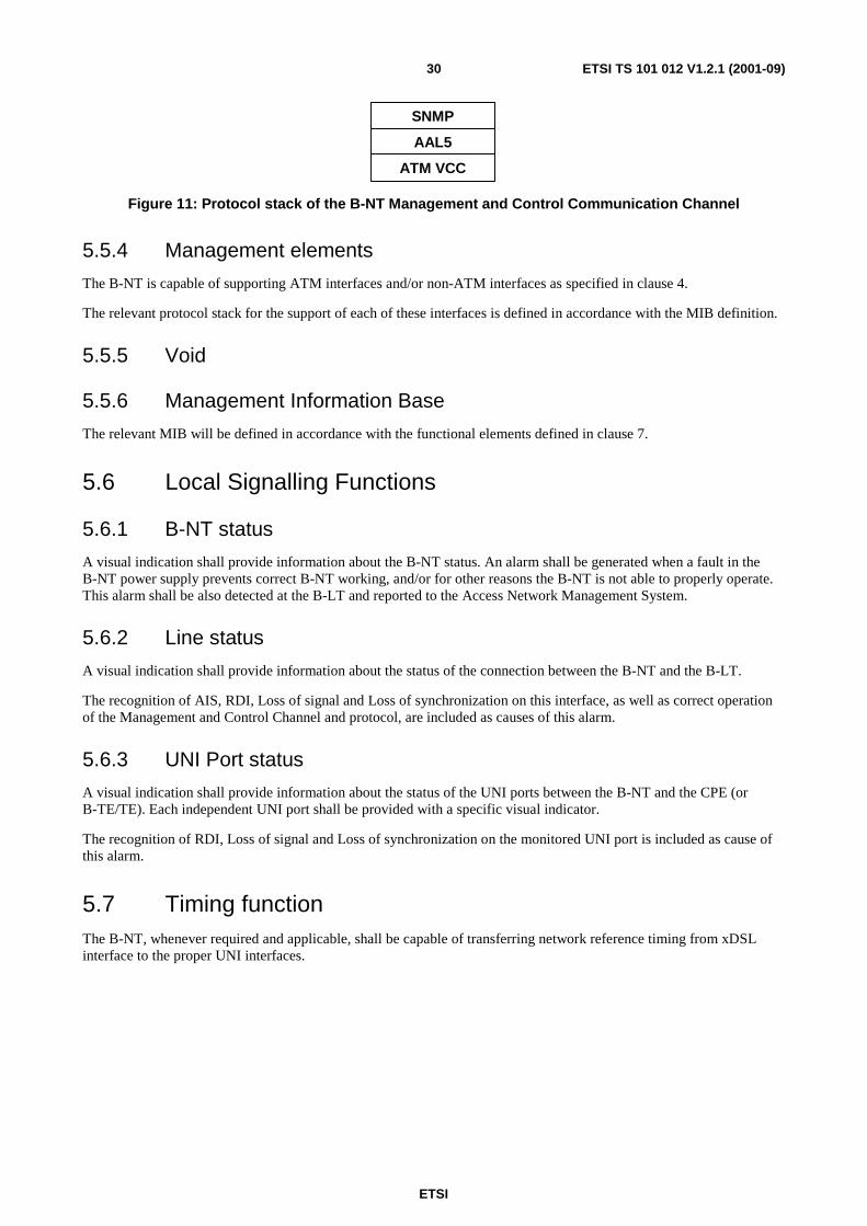
ETSI
ETSI TS 101 012 V1.2.1 (2001-09)30
ATM VCC
AAL5
SNMP
Figure 11: Protocol stack of the B-NT Management and Control Communication Channel
5.5.4 Management elements
The B-NT is capable of supporting ATM interfaces and/or non-ATM interfaces as specified in clause 4.
The relevant protocol stack for the support of each of these interfaces is defined in accordance with the MIB definition.
5.5.5 Void
5.5.6 Management Information Base
The relevant MIB will be defined in accordance with the functional elements defined in clause 7.
5.6 Local Signalling Functions
5.6.1 B-NT status
A visual indication shall provide information about the B-NT status. An alarm shall be generated when a fault in the B-NT power supply prevents correct B-NT working, and/or for other reasons the B-NT is not able to properly operate. This alarm shall be also detected at the B-LT and reported to the Access Network Management System.
5.6.2 Line status
A visual indication shall provide information about the status of the connection between the B-NT and the B-LT.
The recognition of AIS, RDI, Loss of signal and Loss of synchronization on this interface, as well as correct operation of the Management and Control Channel and protocol, are included as causes of this alarm.
5.6.3 UNI Port status
A visual indication shall provide information about the status of the UNI ports between the B-NT and the CPE (or B-TE/TE). Each independent UNI port shall be provided with a specific visual indicator.
The recognition of RDI, Loss of signal and Loss of synchronization on the monitored UNI port is included as cause of this alarm.
5.7 Timing function The B-NT, whenever required and applicable, shall be capable of transferring network reference timing from xDSL interface to the proper UNI interfaces.

ETSI
ETSI TS 101 012 V1.2.1 (2001-09)31
5.8 Local powering Local powering will be provided in accordance with relevant CEI/CENELEC safety requirements.
The AC/DC converter may be included in the same enclosure of the B-NT or may be hosted in a separate dedicated box. The main characteristics of local powering are the following:
AC Voltage: 230 V
AC Voltage tolerance: +10 %/-15 %
(230 V + 10 %, 220 V - 10 %)
AC frequency: 50 Hz
AC frequency tolerance: +2 Hz
Troubled operation: +5 Hz and voltage in range 0 V to 198 V (see note)
NOTE: No destruction and automatic return to the operating condition.
Storage time: > 20 ms with 230 V and rated load
Transient disturbance: IEC 60664 [27], installation category 2, (2,5 kV, 1,2 µs/50 µs)
Noise immunity against line-conducted,
pulse formed disturbances: EN 61000-4-5 [28]:1996, pulse form 1,2 µs/50 µs, 2 kV core against earth
4 kV core against earth
Noise immunity according to EN 50082-2:
Burst EN 61000-4-4 [29], 4 kV
ESD EN 61000-4-2 [30], 4 kV/8 kV (contact-/air discharge)
Protection class: II according to EN 60950 [31]
5.9 Activation/deactivation For further study
5.10 Atomic model of a B-NT supporting ATM UNIs Figure 12 shows the atomic functional representation of B-NT supporting single or multiple ATM UNIs.

ETSI
ETSI TS 101 012 V1.2.1 (2001-09)32
Avp_TT
TCP
CPCP
Avp_C
TCP
Internal channels (e.g. Mgt. & Control Comm. Channel)
Tp/Avp_AATM 25
Tp/Avp_A
0..i ATM UNIs
VP-CrossConnect
Fast IInterlv.
ADSL pmd_TT
ADSL pmd/s_A
ADSL s_TT
AS0..1 LS0..1 ADSL tp_TT
ATM25 pmd_TT
ATM25 pmd/s_A
ATM 25 tp_TT
AvpT/Avp
AvpT
VP Policing
TCP
TCP
ADSL line Interface
ATM25 s/tp_A
ATM25 s_TT
ATMUNITerm. ATU- R
TCP
Avp/Avc_A
Avc_TT
Avc/HL_ACP
CPCP
Avc_CVC-CrossConnect
UserSide
TCP
ATMFunctions
Figure 12: Atomic model of an xDSL based B-NT supporting ATM UNIs
As for the reference configuration the atomic functional representation is independent from the number of atomic functions replicated inside the network element, in this case the B-NT. The detailed description of each atomic function shown in figure 4 is given in dedicated clauses of the present document.
6 B-LT and B-TE Functional Requirements For further study.
7 Functional Model and Processes
7.1 Introduction This clause defines the functions of the different layers and sublayers incorporated in the B-NT, using the functional atomic model defined in [18].

ETSI
ETSI TS 101 012 V1.2.1 (2001-09)33
7.2 Modelling of Transfer and Layer Management Functions Figure 13 shows all the atomic functions which can be included in the ADSL NT at the ADSL side, based on ATM layer modelling defined in [18], [21] and ADSL modelling proposed in the present document.
ADSL Transm. Path Layer
ADSL Section Layer
ATM VP Layer
ADSL PMD Layer
Fast Interleaved
ADSL pmd_TT
ADSL pmd/s_A
ADSL s_TT
ADSL s/tp_A
ADSL Transm. Path Layer Adaptation: Asynchr. mux of VPC in each ASx/LSx channel/ Cell rate decoupling/ HEC proc. /Payload (de)scrambling
ATM VP Trail Termination: F4 processing
ADSL/ Transm. Path Layer Termination: Specific ASx/LSx maintenance (if defined)
Sect. /Transm. Path Layer Adaptation: ASx/LSx multiplexing in fast/interleaving channels/ Cell Rate synchronization
Section Layer Termination: CRC/FEC calculation/ setting of relevant counters and indicators
PMD/Section Layer Adapt.: (De)Interlv. of interlvd. channels bit stream distribution/reassembly to/from DMT carriers
PMD Layer Termination: Pilot tone detection/generation Relevant alarm/indicators setting
ATM VC Layer
ATM VC Trail Term.: F5 processing
ATM VP/ VC layer Adaptation: Asynchr. mux of VCCs in each VPC, VCI Assignment
ATM VC/Higher layer LinkAdaptation (AAL5 for IP, etc.)
Higher layers functions
Avp/Avc
ATM VP Connection Function
Avc/XXX
ATM VC Connection
ADSL tp/Avp_A
LS0..1 AS0..1
Avp_TT
ADSL tp_TT
Avp_C
AvpT/Avp
AvpT
ATM VP Traffic Mgt.: UPC/ Traffic shaping
Avc_C
ATM VP Traffic Mgt.: UPC/ Traffic shaping AvpT/Avp
AvpT
Figure 13: Representation of atomic functions for ADSL/ATM based NT

ETSI
ETSI TS 101 012 V1.2.1 (2001-09)34
7.3 ATM Layer Functions
7.3.1 ADSL TP to ATM VP Adapt. Source Function (ADSLtp/Avp_A_So)
Reference: [15], clauses 7.2 and 8.2.
Symbol:
ADSLtp/Avp_A
Avp_CI
ADSLtp_AI
ADSLtp/Avp_A_So_MI
Processes:
The ADSLtp/Avp_A_So function provides adaptation from the ATM Virtual Path layer to the ADSL transmission path. This is performed by a grouping of specific processes and common processes according to the following list:
• Specific Processes (characterized by the Virtual Path Identifier):
- VP activation/deactivation;
- ATM VPs asynchronous multiplexing;
- VPI setting.
• Common Processes:
- Congestion control (selective cell discard based on CLP);
- GFC processing;
- TP usage measurement;
- Cell rate decoupling;
- HEC generation;
- Payload scrambling;
- Cell stream mapping in ASx/LSx channels.
For a detailed description of the above processes refer to EN 301 163-2-1 [18].
Interfaces:
Table 7: ADSL_tp/Avp_A_So input and output signals
Input(s) Output(s) Avp_CI_D (ATM cell data - VP specific) Avp_CI_ACS (cell start indication) ADSLtp/Avp_A_So_MI_VPI-KActive (Activation VPI-K) ADSLtp/Avp_A_So_MI_TPusgActive (Activation TP usage measurement)
ADSLtp(i)_AI_D (i: AS0..1 -> DS, LS0..1 -> US)) ADSLtp(i)_AI_CLK (TP bit clock) ADSLtp/Avp_A_So_MI_pUser_Total-I ADSLtp/Avp_A_So_MI_pUser_Total-F ADSLtp/Avp_A_So_MI_pCong

ETSI
ETSI TS 101 012 V1.2.1 (2001-09)35
Defects: None.
Consequent Actions: None.
Defect Correlations: None.
Performance Monitoring:
pUser_Total-I: Counter of the total number of cells in the interleaved data path delivered at the input of the function.
pUser_Total-F: Counter of the total number of cells in the fast data path delivered at the input of the function.
pCong: Counter of Congestion events.
7.3.2 ADSL TP Layer to ATM VP Adapt. Sink Funct. (ADSLtp/Avp_A_Sk)
Reference: [15], clauses 7.2 and 8.2.
Symbol:
ADSLtp/Avp_A
Avp_CI
ADSLtp_AI
ADSLtp/Avp_A_Sk_MIADSLtp/Avp_A_RI
Processes:
The ADSLtp/Avp_A_Sk function provides adaptation from the ADSL transmission path to the ATM Virtual Path layer. This is performed by a grouping of specific processes and common processes according to the following list:
• Common Processes:
- TP usage measurement;
- Congestion Control;
- Cell delineation;
- Payload descrambling;
- HEC processing;
- Header verification (only error detection);
- Cell rate decoupling;
- GFC processing;
- VPI verification.
• Specific Processes (characterized by the Virtual Path Identifier):
- ATM VPs asynchronous demultiplexing;
- VP-AIS insertion.

ETSI
ETSI TS 101 012 V1.2.1 (2001-09)36
Interfaces:
Input(s) Output(s) ADSLtp(i)_AI_D (i: AS0..1 -> DS, LS0..1 -> US)) ADSLtp(i)_AI_CLK (TP bit clock) ADSLtp_AI_TSF (trail signal fail) ADSLtp/Avp_A_Sk_MI_VPI-KActive (Activation VPI-K) ADSLtp/Avp_A_Sk_MI_VPIrange (Valid VPI range) ADSLtp/Avp_A_Sk_MI_TPusgActive (Activation TP usage measurement) ADSLtp/Avp_A_Sk_MI_DFLOC (Defect location field contents for VP-AIS cell)
Avp_CI_D (ATM cell data - VP specific) Avp_CI_ACS (cell start indication) Avp_CI_SSF (server signal fail) ADSLtp/Avp_A _RI_NCD-I ADSLtp/Avp_A _RI_NCD-F ADSLtp/Avp_A_RI_HEC-I ADSLtp/Avp_A_RI_HEC-F ADSLtp/Avp_A_Sk_MI_cLCD-I ADSLtp/Avp_A_Sk_MI_cLCD-F ADSLtp/Avp_A_Sk_MI_pInvHead ADSLtp/Avp_A_Sk_MI_pHEC_Viol-I ADSLtp/Avp_A_Sk_MI_pHEC_Viol-F ADSLtp/Avp_A_Sk_MI_pHEC_Total-I ADSLtp/Avp_A_Sk_MI_pHEC_Total-F ADSLtp/Avp_A_Sk_MI_pCong
Anomalies:
No Cell Delineation (ncd-I) anomaly: A ncd-I anomaly occurs immediately after ADSLtp/Avp_A_Sk start-up when ATM data are allocated to the interleaved buffer and as long as the cell delineation process operating on these data is in the HUNT or PRESYNC state. Once cell delineation is acquired, subsequent losses of cell delineation shall be considered ocd-I anomalies;
No Cell Delineation (ncd-F) anomaly: A ncd-F anomaly occurs immediately after ADSLtp/Avp_A_Sk start-up when ATM data are allocated to the fast buffer and as long as the cell delineation process operating on these data is in the HUNT or PRESYNC state. Once cell delineation is acquired, subsequent losses of cell delineation shall be considered ocd-I anomalies;
Out of Cell Delineation (ocd-I) anomaly: An ocd-I anomaly occurs when ATM data are allocated to the interleaved buffer and the cell delineation process operating on these data transitions from SYNC to HUNT state. An ocd-I anomaly terminates when the cell delineation process transitions from PRESYNC to SYNC state or when the dLCD-I defect maintenance state is entered;
Out of Cell Delineation (ocd-F) anomaly: An ocd-F anomaly occurs when ATM data are allocated to the fast buffer and the cell delineation process operating on these data transitions from SYNC to HUNT state. An ocd-F anomaly terminates when the cell delineation process transitions from PRESYNC to SYNC state or when the dLCD-F defect maintenance state is entered;
Header Error Check (hec-I) anomaly: A hec-I anomaly occurs when an ATM cell header error check fails on the interleaved data;
Header Error Check (hec-F) anomaly: A hec-F anomaly occurs when an ATM cell header error check fails on the fast data.
Defects:
dLCD-I: ALoss of Cell Delineation defect: for interleaved data buffer occurs when at least one ocd-I anomaly is present in each of 4 consecutive superframes and no dLOF defect is present. A dLCD-I defect terminates when no ocd-I anomaly is present in 4 consecutive superframes;
dLCD-F: ALoss of Cell Delineation defect: for fast data buffer occurs when at least one ocd-F anomaly is present in each of 4 consecutive superframes and no dLOF defect is present. A dLCD-F defect terminates when no ocd-F anomaly is present in 4 consecutive superframes.

ETSI
ETSI TS 101 012 V1.2.1 (2001-09)37
Consequent Actions: aSSF aTSF or dLCD-F or dLCD-I
aAIS aTSF or dLCD-F or dLCD-I
aRDI_NCD-I ncd-I or ocd-I or dLCD-I
aRDI_NCD-F ncd-F or ocd-F or dLCD-F
aREI_HEC-I hec-I
aREI_HEC-F hec-F
Defect Correlations: cLCD-I dLCD-I and no aTSF
cLCD-F dLCD-F and no aTSF
Performance Monitoring:
pCong: Counter of Congestion events.
pHEC_Viol-I: Counter of discarded cells due to invalid HEC checksum in interleaved buffer.
pHEC_Viol-F: Counter of discarded cells due to invalid HEC checksum in fast buffer.
pHEC_Total-I: Counter of total number of cells while the cell delineation process in sync state in interleaved buffer.
pHEC_Total-F: Counter of total number of cells while the cell delineation process in sync state in fast buffer.
pInvHead: Counter of discarded cells due to invalid header patterns or invalid VPI's (out of range or not assigned).
ATM Virtual Path Layer Functions.

ETSI
ETSI TS 101 012 V1.2.1 (2001-09)38
AvpmAvp AvpAvp_RI
Avp_CI Avp_CI
AvpS_RI
AvpSAvpS
AvpS/Avp AvpS/AvpA v p
Avp_AI Avp_AI
AvpS_AI AvpS_AI
AvpT AvpT
AvpT/AvpAvpT/Avp
Avplb A vp lb
Avpm_RIAvplb_RI
A v p A v p Avp_RI
A v p _ C I A v p _ C I
A v p / A v c
A v c _ C I
A v p S _ R I
A v p S A v p S
A v p S / A v p A v p S / A v p A v p
A v p _ A I A v p _ A I
A v p S _ A I A v p S _ A I
. . . .
A v p / A v c A v p / A v c
A v c _ C I A v c _ C I
. . . .
A v p / A v c A v p / A v c A v p / A v c
A v c _ C I A v c _ C I A v c _ C I
Figure 14: ATM Virtual Path layer network atomic functions
7.3.3 ATM Virtual Path Connection Function (Avp_C)
Symbol:
Avp
Avp_CI
Avp_C_MI
Avp_CI
Figure 15: Avp_C symbol

ETSI
ETSI TS 101 012 V1.2.1 (2001-09)39
Interfaces:
Table 8: Avp_C input and output signals
Input(s) Output(s) Per Avp_CI, n x for the function: Avp_CI_D Avp_CI_ACS for inputs from the server layer: Avp_CI_SSF Avp_CI_CNGI per input and output connection point: Avp_C_MI_ConnectionPortIds per matrix connection: Avp_C_MI_ConnectionType Avp_C_MI_Directionality
per Avp_CI, m x per function: Avp_CI_D Avp_CI_ACS Avp_CI_SSF for outputs to the AvpT_TT_Sk: Avp_CI_CNGI
Processes:
In the Avp_C function ATM Virtual Path Layer Characteristic Information is routed between input (termination) connection points ((T)CPs) and output (T)CPs by means of matrix connections.
NOTE 1: Neither the number of input/output signals to the connection function, nor the connectivity is specified in the present document. That is a property of individual network elements.
NOTE 2: If CI_SSF is not connected (when connected to the client layer TT_So), CI_SSF is assumed to be false.
Figure 34 present a subset of the atomic functions that can be connected to this ATM Virtual Path connection function: ATM Virtual Path trail termination functions, ATM Virtual Path Segment trail termination and adaptation functions, ATM Virtual Path Traffic Management functions and ATM Virtual Path non-intrusive Monitor functions. In addition, adaptation functions in the ATM Virtual Path server layers shall be connected to this ATM Virtual Path connection function.
Routing: The function shall be able to connect a specific input with a specific output by means of establishing a matrix connection between the specified input and output. It shall be able to remove an established matrix connection.
Each (matrix) connection in the Avp_C function is characterized by the following parameters:
Type of connection: unprotected, 1+1 protected (for further study)
Traffic direction: unidirectional, bidirectional
Input and output connection points: set of connection point identifiers (refer to ETS 300 417-1-1 [25], clause 3.3.6)
NOTE 3: Multipoint connections are handled as separate connections from the same input CP and are for further study.
NOTE 4: It will be possible to connect one or more Characteristic Information (CI) outputs to one input Connection Point (CP) of the Avp_C function.
Defects: None.
Consequent Actions:
If an output of this function is not connected to one of its inputs, the connection function will send no cells and SSF = false to the output.
Defect Correlations: None.
Performance Monitoring: None.
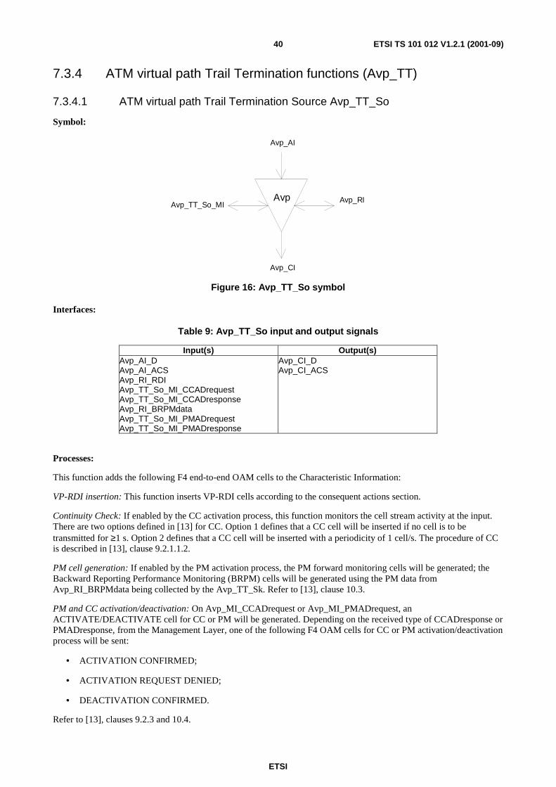
ETSI
ETSI TS 101 012 V1.2.1 (2001-09)40
7.3.4 ATM virtual path Trail Termination functions (Avp_TT)
7.3.4.1 ATM virtual path Trail Termination Source Avp_TT_So
Symbol:
Avp
Avp_AI
Avp_CI
Avp_TT_So_MIAvp_RI
Figure 16: Avp_TT_So symbol
Interfaces:
Table 9: Avp_TT_So input and output signals
Input(s) Output(s) Avp_AI_D Avp_AI_ACS Avp_RI_RDI Avp_TT_So_MI_CCADrequest Avp_TT_So_MI_CCADresponse Avp_RI_BRPMdata Avp_TT_So_MI_PMADrequest Avp_TT_So_MI_PMADresponse
Avp_CI_D Avp_CI_ACS
Processes:
This function adds the following F4 end-to-end OAM cells to the Characteristic Information:
VP-RDI insertion: This function inserts VP-RDI cells according to the consequent actions section.
Continuity Check: If enabled by the CC activation process, this function monitors the cell stream activity at the input. There are two options defined in [13] for CC. Option 1 defines that a CC cell will be inserted if no cell is to be transmitted for ≥1 s. Option 2 defines that a CC cell will be inserted with a periodicity of 1 cell/s. The procedure of CC is described in [13], clause 9.2.1.1.2.
PM cell generation: If enabled by the PM activation process, the PM forward monitoring cells will be generated; the Backward Reporting Performance Monitoring (BRPM) cells will be generated using the PM data from Avp_RI_BRPMdata being collected by the Avp_TT_Sk. Refer to [13], clause 10.3.
PM and CC activation/deactivation: On Avp_MI_CCADrequest or Avp_MI_PMADrequest, an ACTIVATE/DEACTIVATE cell for CC or PM will be generated. Depending on the received type of CCADresponse or PMADresponse, from the Management Layer, one of the following F4 OAM cells for CC or PM activation/deactivation process will be sent:
• ACTIVATION CONFIRMED;
• ACTIVATION REQUEST DENIED;
• DEACTIVATION CONFIRMED.
Refer to [13], clauses 9.2.3 and 10.4.

ETSI
ETSI TS 101 012 V1.2.1 (2001-09)41
Defects: None.
Consequent Actions:
On declaration of RI_RDI, the function will output VP-RDI OAM cells according to ETS 300 404 [13] clause 9.2.1.1.1.2; on clearing of RI_RDI, the generation of VP-RDI cells will be stopped. If implemented, the defect type and defect location field of the VP-RDI cell will contain the value provided by the Avp_TT_Sk. If these fields are not used, the binary contents will be coded as 6AHex.
Defect Correlations: None.
Performance Monitoring: None.
7.3.4.2 ATM Virtual Path Trail Termination Sink (Avp_TT_Sk)
Symbol:
Avp
Avp_AI
Avp_CI
Avp_TT_Sk_MI Avp_RI
Figure 17: Avp_TT_Sk symbol
Interfaces:
Table 10: Avp_TT_Sk input and output signals
Input(s) Output(s) Avp_CI_D Avp_CI_ACS Avp_CI_SSF Avp_TT_Sk_ MI_RDIreported Avp_TT_Sk_ MI_AISreported
Avp_AI_D Avp_AI_ACS Avp_AI_TSF Avp_RI_RDI Avp_RI_BRPMdata Avp_TT_Sk_MI_CCADrequest Avp_TT_Sk_MI_CCADreport Avp_TT_Sk_MI_PMADrequest Avp_TT_Sk_MI_PMADreport Avp_TT_Sk_MI_cRDI Avp_TT_Sk_MI_RDIdata Avp_TT_Sk_MI_cAIS Avp_TT_Sk_MI_AISdata Avp_TT_Sk_MI_cLOC Avp_TT_Sk_MI_pXXX

ETSI
ETSI TS 101 012 V1.2.1 (2001-09)42
Processes:
This function extracts all the F4 end-to-end OAM cell from the Characteristic Information as follows:
VP-RDI: The information carried in the F4 OAM RDI cell will be extracted. The VP-RDI provides information as to the status of the remote receiver, as well as to the defect type and defect location. The information extracted from the defect type and defect location field is reported to the EMF via MI_RDIdata. The presence of an RDI cell indicates a Remote Defect Indication state, while the absence of RDI cells for longer than 2,5 s ± 0,5 s indicates the normal, working state. Refer to [13], clauses 9.2.1.1.1.2 and 10.2.1.
VP-AIS: The information carried in the F4 OAM AIS cell will be extracted. The VP-AIS provides information as to the status of the VP connection, as well as to the defect type and defect location. The information extracted from the defect type and defect location field is reported to the EMF via MI_AISdata. The presence of an AIS cell indicates an Alarm Indication state, while the reception of a user cell or CC cell indicates the normal, working state. In case of Continuity Check is not activated, the absence of AIS cells for longer than 2,5 s ± 0,5 s also indicates the normal, working state. Refer to [13], clauses 9.2.1.1.1.1 and 10.2.1.
PM and CC activation/deactivation: If a CC or PM ACTIVATE request cell is received, MI_CCAD request or MI_PMADrequest is generated towards the Management Layer. On receipt of ACTIVATION CONFIRMED, ACTIVATION REQUEST DENIED or DEACTIVATION CONFIRMED F4 end-to-end OAM cell, a MI_PMADreport, resp. MI_CCADreport is send to the Management Layer. For more detail see [13] clause 9.2.3 and annex B.
NOTE 1: In case this function detects F4 segment OAM cells that were not extracted by the segment termination function, these cells will be discarded.
NOTE 2: According to ETS 300 404 [13], clause 9.2.1.1.2, permanent end-to-end CC mechanism will be provided simultaneously for all reserved, permanent and semi-permanent VPCs.
Defects:
If enabled by the CC activation process, the function will declare dLOC if no user cell or continuity check cell is received within a time interval of 3,5 s, with a margin of ±0,5 s (sliding window). Refer to [13], clause 9.2.1.1.2. dLOC will be cleared when any user cell or CC cell is received. Also refer to [3], clause 5.6.1.1.2.
The function will declare dRDI on receipt of a VP-RDI cell. dRDI will be cleared when no VP-RDI is received during a nominally 2,5 s period, with a margin of ±0,5 s. Refer to [6], clause 9.2.1.1.1.2.
The function will detect for dAIS defect according [13], clause 9.2.1.1.1.1.
Consequent Actions:
aTSF ← CI_SSF or dLOC or dAIS
aRDI ← CI_SSF or dLOC or dAIS
The consequent action aRDI is conveyed through RI_RDI to the Avp_TT_So together with the defect type and defect location (if implemented). In case of dAIS, defect type and location through RI_RDI are as in the received VP-AIS cell. In case of CI_SSF and dLOC, defect type and location are in respect to the equipment this function is built into.
NOTE 3: VC-AIS insertion is performed in the Avp/Avc_A_Sk function under control of AI_TSF.
Defect Correlations:
cRDI ← dRDI and RDIreported
cAIS ← dAIS and (not CI_SSF) and AISreported
cLOC ← dLOC and (not CI_SSF) and (not dAIS)
It will be an option to report AIS as a fault cause. This is controlled by means of the parameter AISreported. The default will be AISreported = false.

ETSI
ETSI TS 101 012 V1.2.1 (2001-09)43
Performance Monitoring:
If activated by the PM activation process, the function will monitor the performance derived from the comparison between received block of user cells and information in a received PM cell. The definition of user cells is given in [13] table 1. The result is backward reported via RI_BRPMdata.
NOTE 4: Supported parameters (e.g. Near/Far End Defect Seconds (pN_DS, pF_DS), Cell Loss Ratio, Cell Error Ratio, Cell Misinsertion Rate) as well as the process need to be added. PM will detect errored blocks and total received user cell counts. Performances or backward report results of the received PM cell are reported via MI_pxxx.
7.3.5 ATM Virtual Path Monitoring Functions
7.3.5.1 ATM Virtual Path Non-intrusive Monitoring Function Avpm_TT_Sk
Symbol:
Avpm
Avp_AI_TSF
Avp_CI
Avpm_TT_Sk_MI Avpm_RI
Figure 18: Avpm_TT_Sk symbol
Interfaces:
Table 11: Avpm_TT_Sk input and output signals
Input(s) Output(s) Avp_CI_D Avp_CI_ACS Avp_CI_SSF Avpm_TT_Sk_MI_AISreported Avpm_TT_Sk_MI_RDIreported Avpm_TT_Sk_MI_LOCreported Avp_TT_Sk_MI_Lbdiscard Avpm_TT_Sk_RI_Lbtimer
Avp_AI_TSF Avpm_TT_Sk_RI_Lbresponse Avpm_TT_Sk_MI_cAIS Avpm_TT_Sk_MI_AISdata Avpm_TT_Sk_MI_cRDI Avpm_TT_Sk_MI_RDIdata Avpm_TT_Sk_MI_cLOC Avpm_TT_Sk_MI_Lbdata Avpm_TT_Sk_MI_Lbfail Avpm_TT_Sk_MI_pXXX
Processes:
This function monitors the following F4 end-to-end OAM cell flow:
VP-RDI: The information carried in the F4 OAM RDI cell will be monitored. The VP-RDI provides information as to the status of the remote receiver, as well as to the defect type and defect location. The information extracted from the defect type and defect location field is reported to the EMF via MI_RDIdata. The presence of an RDI cell indicates a Remote Defect Indication state, while the absence of RDI cells for longer than 2,5 s ± 0,5 s indicates the normal, working state. Refer to [13], clauses 9.2.1.1.1.2 and 10.2.1.

ETSI
ETSI TS 101 012 V1.2.1 (2001-09)44
VP-AIS: The information carried in the F4 OAM AIS cell will be monitored. The VP-AIS provides information as to the status of the VP connection, as well as to the defect type and defect location. The information extracted from the defect type and defect location field is reported to the EMF via MI_AISdata. The presence of an AIS cell indicates an Alarm Indication state, while the reception of a user cell or CC cell indicates the normal, working state. In case of Continuity Check is not activated, the absence of AIS cells for longer than 2,5 s ± 0,5 s also indicates the normal, working state. Refer to [13], clauses 9.2.1.1.1.1 and 10.2.1.
NOTE 1: [13] currently does not specify Continuity Check at intermediate Connection Points. Continuity Check could be useful in future for, e.g. SNC protection. This issue is for further study.
Loopback processing:
If MI_LBdiscard=false, the function will monitor the cell flow for F4 OAM end-to-end Loopback cells being inserted by the Avplb_TT_So function. On RI_LBtimer from Avplb_TT_So, a 5 s timer is started. If within this time period an F4 OAM end-to-end Loopback cell with Loopback Indication set to "0" is monitored, an MI_LBcompleted indication is generated and the received LLID and Source ID reported to the EMF via MI_LBdata; if no Loopback cell with Loopback Indication set to "0" is received within this time period, an MI_LBfail indication is generated. Refer to [13], clause 9.2.1.1.3, network-to-endpoint loopback.
If MI_LBdiscard=false, the function will monitor the cell flow for F4 OAM segment Loopback cells being inserted by the Avplb_TT_So function. If an F4 OAM segment Loopback cell with Loopback Indication set to "1" and an LLID matching the CPID or an LLID = all "1"s is received, this function copies and forwards the cell via RI_LBresponse to the Avplb_TT_So function for insertion of the Loopback cell in reverse direction. Refer to [13], clause 9.2.1.1.3, connecting point for single and multiple loopback technique.
Table 12 summarizes these conditions.
Table 12: Loopback conditions
Received cell (LBdiscard=false)
Loopback indication
LLID Action
e-t-e loopback cell 0 - any value If LBtimer < 5 s:- report LBcompleted - LLID / Source ID reported to LBdata
If LBtimer > 5 s:- report LBfail segment loopback cell 1 - all ONE's or
- LLID=CPID - copy loopback cell to LBresponse
PM and CC activation/deactivation: If a CC or PM ACTIVATE request cell is received, MI_CCAD request or MI_PMADrequest is generated towards the Management Layer. On receipt of ACTIVATION CONFIRMED, ACTIVATION REQUEST DENIED or DEACTIVATION CONFIRMED F4 end-to-end OAM cell, a MI_PMADreport, resp. MI_CCADreport is send to the Management Layer. For more detail [13] clause 9.2.3 and annex B.
Defects:
If enabled by the CC activation process, the function will declare dLOC if no user cell or continuity check cell is received within a time interval of 3,5 s, with a margin of ±0,5 s (sliding window). Refer to [13], clause 9.2.1.1.2. dLOC will be cleared when any user cell or CC cell is received. Also refer to ITU-T Recommendation I.732 [21], clause 5.6.1.1.2.
The function will declare dRDI on receipt of a VP-RDI cell. dRDI will be cleared when no VP-RDI is received during a nominally 2,5 s period, with a margin of ±0,5 s. Refer to [13], clause 9.2.1.1.1.2.
The function will detect for dAIS defect according to [13] clause 9.2.1.1.1.1.
Consequent Actions:
aTSF ← CI_SSF or dLOC or dAIS

ETSI
ETSI TS 101 012 V1.2.1 (2001-09)45
Defect Correlations:
cRDI ← dRDI and RDIreported
cAIS ← dAIS and (not CI_SSF) and AISreported
cLOC ← dLOC and (not CI_SSF) and (not dAIS) and LOCreported
It will be an option to report AIS as a fault cause. This is controlled by means of the parameter AISreported. The default will be AISreported=false.
Performance Monitoring:
If activated by the PM activation process, the function will monitor blocks of user cells. The definition of user cells is given in [13] table 1.
NOTE 2: Supported parameters (e.g. Near/Far End Defect Seconds (pN_DS, pF_DS), Cell Loss Ratio, Cell Error Ratio, Cell Misinsertion Rate) as well as the process need to be added. PM will detect errored blocks and total received user cell counts. Performances or backward report results of the received PM cell are reported via MI_pxxx.
7.3.6 ATM Virtual Path Segment Functions
Refer to ITU-T Recommendation I.732 [21].
7.3.7 ATM Virtual Path Traffic Management Functions
NOTE 1: VP traffic management functions (UPC/NPC and VP traffic shaping) are described differently in ITU-T Recommendation I.732 [21], where they are indicated to be part of the VP Link Termination atomic functions, corresponding in [18] to the ATM VP Trail termination functions. It has to be decided which modelling methodology will be applied in the present document.
NOTE 2: The ATM Virtual Path Traffic Management Functions are, if activated, always present as a set. If active, the Avp_CI output of the AvpT/Avp_A_Sk is always connected to the Avp_CI input of the AvpT/Avp_A_So as shown in figure 43. This model allows the insertion of additional traffic management functions by not inserting and additional sub-layer in the network architecture view.
Avp_CI Avp_CI
AvpT/Avp
AvpT
AvpT/Avp
AvpT
Figure 19: Model of active AvpT Traffic Management functions

ETSI
ETSI TS 101 012 V1.2.1 (2001-09)46
7.3.7.1 ATM VP Traffic Management Trail Termination Source function (AvpT_TT_So)
Symbol:
AvpT
AvpT_AI
Avp_CI
AvpT_TT_So_MI
Figure 20: AvpT_TT_So symbol
Interfaces:
Table 13: AvpT_TT_So input and output signals
Input(s) Output(s) AvpT_AI_D AvpT_AI_ACS AvpT_AI_TSF AvpT_AI_CNGI
Avp_CI_D Avp_CI_ACS Avp_CI_SSF
Processes:
EFCI setting: This function is optional. The insertion of EFCI is driven by the input AvpT_AI_CNGI from the S4/AvpG_A_Sk. The EFCI setting is done in the PTI field of the cell header on all VPs of this CI. For the coding, refer to [20]. The PTI field will not be changed if the NE is not congested.
NOTE: The current model for EFCI setting only works in sink direction. The modelling in source direction is for further study
Defects: None.
Consequent Actions:
aSSF ← AI_TSF
On declaration of AI_CNGI, any congested NE, upon receiving a user data cell, may modify the PTI as follows: Cells received with PTI=000 or PTI=010 are transmitted with PTI=010. Cells received with PTI=001 or PTI=011 are transmitted with PTI=011. For the use of EFCI, refer to [19].
Defect Correlations: None.
Performance Monitoring: None.

ETSI
ETSI TS 101 012 V1.2.1 (2001-09)47
7.3.7.2 ATM Virtual Path Traffic Management Trail Termination Sink function (AvpT_TT_Sk)
Symbol:
AvpT
AvpT_AI
Avp_CI
AvpT_TT_Sk_MI
Figure 21: AvpT_TT_Sk symbol
Interfaces:
Table 14: AvpT_TT_Sk input and output signals
Input(s) Output(s) Avp_CI_D Avp_CI_ACS Avp_CI_SSF Avp_CI_CNGI AvpT_TT_Sk _MI_ShapingActive AvpT_TT_Sk _MI_UPC/NPCactive AvpT_TT_Sk _MI_VpusgActive
AvpT_AI_D AvpT_AI_ACS AvpT_AI_TSF AvpT_AI_CNGI AvpT_TT_Sk_MI_pXXX
Processes:
This function performs the UPC/NPC, VP traffic shaping and VP usage measurement per VPC.
UPC/NPC: This function is optional. If implemented, the UPC/NPC function can be activated/deactivated by UPC/NPCactive. If activated, it will detect violations of negotiated traffic parameters for purpose of protecting the QoS of other VPCs. The use of UPC may be required, whereas the use of NPC is optional. Processes and requirements of UPC/NPC are described in [19].
NOTE 1: The use of UPC in ATM equipment on the user side of SB and TB reference point is optional.
VP traffic shaping: This function is optional. If implemented, the shaping function can be activated/deactivated by MI_ShapingActive. If activated, it will perform traffic shaping according to [19].
NOTE 2: The VP traffic shaping function should not be simultaneously activated on both sink and source directions of the same VPC.
VP usage measurement: This function is optional. If enabled by VPusgActive, this function will count the incoming cells on the VPC.
Defects: None.
Consequent Actions:
aCNGI ← CI_CNGI
aTSF ← CI_SSF
Defect Correlations: None.

ETSI
ETSI TS 101 012 V1.2.1 (2001-09)48
Performance Monitoring:
The Performance Monitoring parameters are for further study. The following parameters need to be defined:
• VP usage measurement: Count for CLP=0+1; Count for CLP=0;
• UPC/NPC (tagged cell count): Count for CLP=0+1; Count for CLP=0.
7.3.7.3 ATM VP Traffic Management to ATM VP Adaptation Source function (AvpT/Avp_A_So)
Symbol:
AvpT/Avp
Avp_CI
AvpT_AI
Figure 22: AvpT/Avp_A_So symbol
Interfaces:
Table 15: AvpT/Avp_A_So input and output signals
Input(s) Output(s) Avp_CI_D Avp_CI_ACS Avp_CI_SSF Avp_CI_CNGI AvpT/Avp_A_So_MI_Active
AvpT_AI_D AvpT_AI_ACS AvpT_AI_TSF AvpT_AI_CNGI
NOTE: If activated by MI_Active, the input of this function is always connected to the AvpT/Avp_A_Sk function.
Processes: None.
Defects: None.
Consequent Actions:
aTSF ← CI_SSF
aCNGI ← CI_CNGI
Defect Correlations: None.
Performance Monitoring: None.

ETSI
ETSI TS 101 012 V1.2.1 (2001-09)49
7.3.7.4 ATM VP Traffic Management to ATM VP Adapt. Sink function (AvpT/Avp_A_Sk)
Symbol:
AvpT/Avp
Avp_CI
AvpT_AI
Figure 23: AvpT/Avp_A_Sk symbol
Interfaces:
Table 16: AvpT/Avp_A_Sk input and output signals
Input(s) Output(s) AvpT_AI_D AvpT_AI_ACS AvpT_AI_TSF AvpT_AI_CNGI AvpT/Avp_A_Sk_MI_Active
Avp_CI_D Avp_CI_ACS Avp_CI_SSF Avp_CI_CNGI
NOTE: If activated by MI_Active, the output of this function is always connected to the AvpT/Avp_A_So function.
Processes: None.
Defects: None.
Consequent Actions:
aSSF ← AI_TSF
aCNGI ← AI_CNGI
Defect Correlations: None.
Performance Monitoring: None.

ETSI
ETSI TS 101 012 V1.2.1 (2001-09)50
7.3.8 ATM Virtual Path Loopback Functions
7.3.8.1 ATM Virtual Path Loopback Source Function Avplb_TT_So
Symbol:
Avp_CI
Avplb_RIAvpm_RI
Avplb_TT_So_MIAvplb
Figure 24: Avplb_TT_So symbol
Interfaces:
Table 17: Avplb_TT_So input and output signals
Input(s) Output(s) Avplb_RI_Lbresponse Avpm_RI_Lbresponse Avp_TT_So_MI_Lbdiscard Avp_TT_So_MI_Lbrequest
Avp_CI_D Avp_CI_ACS Avplb_RI_LBtimer Avpm_RI_LBtimer
Processes:
This function adds the following F4 loopback OAM cells to the Characteristic Information:
Loopback:
On Avp_MI_LBrequest, an F4 end-to-end loopback cell will be generated with Loopback Indication set to "1". The LLID and Source ID contain the addresses of the loopback point, resp. of the source point. The default value of the Source ID field is the all ONE's pattern. If the LLID field contains an all ONE's pattern, it indicates the end point of the VP connection. If LBdiscard=true, an indication Avplb_RI_LBtimer will be generated to start the timer at Avplb_TT_Sk. If LBdiscard=false, an indication Avpm_RI_LBtimer will be generated to start the timer at Avpm_TT_Sk. Refer to [13], clause 9.2.1.1.3, network-to-endpoint loopback.
On Avp_MI_LBrequest, an F4 segment loopback cell will be generated with Loopback Indication set to "1". The LLID and Source ID contain the addresses of the loopback point (single loopback technique), resp. of the source point. The default value of the Source ID field is the all ONE's pattern. If the LLID field contains an all ONE's pattern, it indicates all intermediate connecting points and the end point of the VP segment (multiple loopback technique). If LBdiscard=true, an indication Avplb_RI_LBtimer will be generated to start the timer at Avplb_TT_Sk. If LBdiscard=false, an indication Avpm_RI_LBtimer will be generated to start the timer at Avpm_TT_Sk. Refer to [13], clause 9.2.1.1.3, intra-domain loopback.
On Avplb_RI_LBresponse (LBdiscard=true) or Avpm_RI_LBresponse (LBdiscard=false), an F4 loopback cell identical to the cell passed through Avplb_RI_LBresponse/Avpm_RI_LBresponse will be generated, but with Loopback Indication set to "0" and the LLID set to the CPID of the Loopback point. Refer to [13], clauses 9.2.1.1.3 (connecting points) and 10.2.4.
The time interval of sending consecutive segment or end-to-end Loopback cells will be longer than 5 seconds.

ETSI
ETSI TS 101 012 V1.2.1 (2001-09)51
7.3.8.2 ATM Virtual Path Loopback Sink Function Avplb_TT_Sk
Symbol:
Avplb
Avp_CI
Avplb_TT_Sk_MI Avplb_RI
Figure 25: Avplb_TT_Sk symbol
Interfaces:
Table 18: Avplb_TT_Sk input and output signals
Input(s) Output(s) Avp_CI_D Avp_CI_ACS Avp_CI_SSF Avp_TT_Sk_MI_Lbdiscard Avplb_TT_Sk_RI_Lbtimer
Avplb_TT_Sk_RI_LBresponse Avplb_TT_Sk_MI_LBdata Avplb_TT_Sk_MI_LBfail
Processes:
This function terminates the following F4 OAM Loopback cells:
Loopback processing:
If MI_LBdiscard=true, the function will terminate the cell flow of F4 OAM end-to-end Loopback cells being inserted by the Avplb_TT_So function. On RI_LBtimer from Avplb_TT_So, a 5 seconds timer is started. If within this time period an F4 OAM end-to-end Loopback cell with Loopback Indication set to "0" is received, an MI_LBcompleted indication is generated and the received LLID and Source ID reported to the EMF via MI_LBdata; if no Loopback cell with Loopback Indication set to "0" is received within this time period, an MI_LBfail indication is generated. Refer to [13], clause 9.2.1.1.3, network-to-endpoint loopback.
If MI_LBdiscard=true, the function will terminate the cell flow of F4 OAM end-to-end Loopback cells being inserted by the Avplb_TT_So function. If an F4 OAM end-to-end Loopback cell with Loopback Indication set to "1" and an LLID matching the CPID or an LLID = all "1"s is received, this function copies and forwards the cell via RI_LBresponse to the Avplb_TT_So function for insertion of the Loopback cell in reverse direction. Refer to [13], clause 9.2.1.1.3, connecting point for single loopback technique.
If MI_LBdiscard=true, the function will terminate the cell flow of F4 OAM segment Loopback cells being inserted by the Avplb_TT_So function. If an F4 OAM segment Loopback cell with Loopback Indication set to "1" and an LLID matching the CPID or an LLID = all "1"s is received, this function copies and forwards the cell via RI_LBresponse to the Avplb_TT_So function for insertion of the Loopback cell in reverse direction. Refer to [13], clause 9.2.1.1.3, connecting point for single and multiple loopback technique.
If MI_LBdiscard=true, the function will terminate the cell flow of F4 OAM segment Loopback cells being inserted by the Avplb_TT_So function. On RI_LBtimer from Avplb_TT_So, a 5 seconds timer is started. If within this time period an F4 OAM segment Loopback cell with Loopback Indication set to "0" is received, an MI_LBcompleted indication is generated and the received LLID and Source ID reported to the EMF via MI_LBdata; if no Loopback cell with Loopback Indication set to "0" is received within this time period, an MI_LBfail indication is generated. Refer to [13], clause 9.2.1.1.3, loopback termination at connecting point for single loopback technique.
Table 19 summarizes these conditions.

ETSI
ETSI TS 101 012 V1.2.1 (2001-09)52
Table 19: Loopback conditions
Received cell (LBdiscard=true)
Loopback indication
LLID Action
e-t-e loopback cell 1 - all ONE's or - LLID=CPID
- copy loopback cell to LBresponse
e-t-e loopback cell 0 - any value If LBtimer < 5 s:- report LBcompleted - LLID / Source ID reported to LBdata
If LBtimer > 5 s:- report LBfail - discard loopback cell
segment loopback cell 1 - all ONE's or - LLID=CPID
- copy loopback cell to LBresponse
segment loopback cell 0 - any value If LBtimer < 5 s:- report LBcompleted - LLID / Source ID reported to LBdata
If LBtimer > 5 s:- report LBfail - discard loopback cell
Defects: None.
Consequent Actions: None.
Defect Correlations: None.
Performance Monitoring: None.
7.3.9 ATM Virtual Path to ATM Virtual Channel Adaptation Functions
7.3.9.1 ATM Virtual Path to ATM Virtual Channel Adaptation Source Avp/Avc_A_So
Symbol:
Avp/Avc
Avc_CI
Avp_AI
Avp/Avc_A_So_MI
Figure 26: Avp/Avc_A_So symbol
Interfaces:
Table 20: Avp/Avc_A_So input and output signals
Input(s) Output(s) Avc_CI_D Avc_CI_ACS Avc_CI_SSF Avp/Avc_A_So_MI_CellDiscardActive Avp/Avc_A_Sk_MI_VCI-Lactive Avp/Avc_A_So_MI_Active
Avp_AI_D Avp_AI_ACS Avp/Avc_A_So_MI_pXXX

ETSI
ETSI TS 101 012 V1.2.1 (2001-09)53
Common Processes:
The Common Processes include: Congestion control and Metasignalling.
Congestion control: If enabled by CellDiscardActive, this function will perform selective cell discard according to CLP value. In the event of congestion, cells with CLP=1 are subject to be discarded prior to cells with CLP=0. See [19] for further details about the use of the CLP.
Metasignalling: The metasignalling cells (refer to [20]) are inserted. This function is optional. The processing of these cells is for further study.
Specific Processes:
These Processes include ATM VC asynchronous multiplexing as well as VCI setting. Each of these Specific Processes is characterized by the Virtual Channel Identifier number L, where 0 ≤ L ≤ 2M - 1.
NOTE: The value of M represents the number of bits in the VCI field and is an integer number. Its maximum value is equal to 16.
VCI setting: Each VCC is characterized by the Virtual Channel Identifier number L, where 0 ≤ L ≤ 2M- 1. This process and the associated VC matrix connection perform the VCI translation.
Activation: The function will access the access point when it is activated (MI_Active is true). Otherwise, it will not access the access point.
Defects: None.
Consequent Actions: None.
Defect Correlations: None.
Performance Monitoring:
The Performance Monitoring parameters are for further study. The following parameters need to be defined:
• Count of discarded cells from congestion control.
7.3.9.2 ATM Virtual Path to ATM Virtual Channel Adaptation Sink Avp/Avc_A_Sk
Symbol:
Avp/Avc
Avc_CI
Avp_AI
Avp/Avc_A_Sk_MI
Figure 27: Avp/Avc_A_Sk symbol

ETSI
ETSI TS 101 012 V1.2.1 (2001-09)54
Interfaces:
Table 21: Avp/Avc_A_Sk input and output signals
Input(s) Output(s) Avp_AI_D Avp_AI_ACS Avp_AI_TSF Avp/Avc_A_Sk_MI_VCIrange Avp/Avc_A_Sk_MI_CellDiscardActive Avp/Avc_A_Sk_MI_VCI-Lactive Avp/Avc_A_Sk_MI_Active
Avc_CI_D Avc_CI_ACS Avc_CI_SSF Avc_CI_CNGI Avp/Avc_A_Sk_MI_pXXX
NOTE: L is the VCI number, where 0 ≤ L ≤ 2M - 1. This parameter defines the VC value within the AI stream the function has access to. The value of M provided by VCIrange represents the number of bits in the VCI fields and is an integer number; its maximum value is equal to 16.
Common Processes:
These Common Processes include: VCI verification, Congestion control and Metasignalling.
VCI verification: This function will verify that the received cell VCI is valid. If the VCI is determined to be invalid (i.e. out-of-range VCI or not assigned), the cell will be discarded. The range of valid VCI values is given by MI_VCIrange.
Congestion control: If enabled by CellDiscardActive, this function will perform selective cell discard according to CLP value. In the event of congestion, cells with CLP=1 are subject to be discarded prior to cells with CLP=0. In the event of congestion, the indication Avc_CI_CNGI is set for the traffic management function AvcT_TT_So to insert EFCI.
See [19] for further details about the use of the CLP.
Metasignalling: The metasignalling cells (refer to [20]) are inserted with VCI=1 (activation of Avp/Avc_A_Sk function with L=1). This function is optional.
Specific Processes:
The function performs demultiplexing and VC-AIS insertion on a per VC basis and is activated if MI_VCI-LActive is true.
VC-AIS insertion: If the Specific Processes are activated, theVC-AIS insertion will be performed as in the Consequent Actions section below.
VC demultiplexing: The adaptation sink function has access to a specific Avc identified by the number L (0 ≤ L ≤ 2M - 1). When the function is activated only the cells of that specific Avc-L are passed towards the Connection Point.
VCI-L Activation: The Specific Processes perform the operation specified above when it is activated (MI_VCI-LActive is true). Otherwise, it will send no cells and SSF=false.
Activation: The Avp/Avc_A_Sk function will perform the Common and Specific Processes operation specified above when it is activated (MI_Active is true). Otherwise, it will activate the SSF signals at its output (CI_SSF) and not report its status via the management point.
Defects: None.
Consequent Actions:
aCNGI ← "Event of Congestion" and CellDiscardActive
aSSF ← AI_TSF
aAIS ← AI_TSF

ETSI
ETSI TS 101 012 V1.2.1 (2001-09)55
On declaration of aAIS the function will output VC-AIS OAM cells according to [13] clause 9.2.2.1.1.1; on clearing of aAIS the generation of VC-AIS cells will be stopped. If implemented, the defect type and defect location field of the VC-AIS cell will be inserted in the information field. The content of these fields is for further study.
Defect Correlations: None.
Performance Monitoring:
The Performance Monitoring parameters are for further study. The parameters for the following functions need to be defined:
• Count of discarded cells from congestion control;
• Count of cells with invalid VCI (one common counter for invalid header/invalid VPI/invalid VCI is maintained).
ATM Virtual Channel Layer Network Functions.
Avcm
AvcT AvcT
AvcT/AvcAvcT/Avc
Avc AvcAvc_RI
Avc_CI Avc_CI
AvcS_RI
AvcSAvcS
AvcS/Avc AvcS/Avc
Avc_AI Avc_AI
AvcS_AI AvcS_AI
Avclb Avclb
Avcm_RIAvclb_RI
Avc
Figure 28: ATM Virtual Channel layer network atomic functions
7.3.10 ATM Virtual Channel Connection Function Avc_C
Symbol:
A vc
Avc_C I
Avc_C _M I
Avc_C I
Figure 29: Avc_C symbol

ETSI
ETSI TS 101 012 V1.2.1 (2001-09)56
Interfaces:
Table 22: Avc_C input and output signals
Input(s) Output(s) per Avc_CI, n x for the function: Avc_CI_D Avc_CI_ACS for inputs from the server layer: Avc_CI_SSF Avc_CI_CNGI per input and output connection point: Avc_C_MI_ConnectionPortIds per matrix connection: Avc_C_MI_ConnectionType Avc_C_MI_Directionality
per Avc_CI, m x per function: Avc_CI_D Avc_CI_ACS Avc_CI_SSF for outputs to the AvcT_TT_Sk: Avc_CI_CNGI
Processes:
In the Avc_C function ATM Virtual Channel Layer Characteristic Information is routed between input (termination) connection points ((T)CPs) and output (T)CPs by means of matrix connections.
NOTE 1: Neither the number of input/output signals to the connection function, nor the connectivity is specified in the present document. That is a property of individual network elements.
NOTE 2: If CI_SSF is not connected (when connected to the client layer TT_So), CI_SSF is assumed to be false.
Figure 52 presents a subset of the atomic functions that can be connected to this ATM Virtual Channel connection function: ATM Virtual Channel trail termination functions, ATM Virtual Channel Segment trail termination and adaptation functions, ATM Virtual Channel Traffic Management functions, ATM Virtual Channel non-intrusive Monitor function. In addition, adaptation functions in the ATM Virtual Channel server layers shall be connected to this ATM Virtual Channel connection function.
Routing: The function shall be able to connect a specific input with a specific output by means of establishing a matrix connection between the specified input and output. It shall be able to remove an established matrix connection.
Each (matrix) connection in the Avc_C function shall be characterized by:
Type of connection: unprotected, 1+1 protected (for further study)
Traffic direction: unidirectional, bidirectional
Input and output connection points: set of connection point identifiers (refer to ETS 300 417-1-1 [25], clause 3.3.6)
NOTE 3: Multipoint connections are handled as separate connections to the same input CP and are for further study.
NOTE 4: It shall be possible to connect one or more Characteristic Information (CI) outputs to one input Connection Point (CP) of the Avc_C function.
Defects: None.
Consequent Actions:
If an output of this function is not connected to one of its inputs, the connection function shall send no cells and SSF=false to the output.
Defect Correlations: None.
Performance Monitoring: None.

ETSI
ETSI TS 101 012 V1.2.1 (2001-09)57
7.3.11 ATM Virtual Channel Trail Termination Functions
7.3.11.1 ATM Virtual Channel Trail Termination Source (Avc_TT_So)
Symbol:
A vc
Avc_AI
Avc_C I
Avc_TT_So_M I Avc_RI
Figure 30: Avc_TT_So symbol
Interfaces:
Table 23: Avc_TT_So input and output signals
Input(s) Output(s)
Avc_AI_D Avc_AI_ACS Avc_RI_RDI Avc_MI_ TT_So_CCADrequest Avc_MI_ TT_So_CCADresponse Avc_RI_BRPMdata Avc_MI_ TT_So_PMADrequest Avc_MI_ TT_So_PMADresponse
Avc_CI_D Avc_CI_ACS
Processes:
This function adds the following F5 end-to-end OAM cells to the Characteristic Information.
VC-RDI insertion: This function inserts VC-RDI cells according to the consequent actions section.
Continuity Check: If enabled by the CC activation process, this function monitors the cell stream activity at the input. There are two options defined in [13] for CC. Option 1 defines that a CC cell is inserted if no cell is to be transmitted for ≥1 s. Option 2 defines that a CC cell is inserted with a periodicity of 1 cell/s. The procedure of CC is described in [13], clause 9.2.1.1.2.
PM cell generation: If enabled by the PM activation process, the PM forward monitoring cells shall be generated; the Backward Reporting Performance Monitoring (BRPM) cells shall be generated using the PM data from Avc_RI_BRPMdata being collected by the Avc_TT_Sk. Refer to [13], clause 10.3.
PM and CC activation/deactivation: On Avc_MI_CCADrequest or Avc_MI_PMADrequest, an ACTIVATE/DEACTIVATE cell for CC or PM shall be generated. Depending on the received type of CCADresponse or PMADresponse, from the Management Layer, one of the following F5 OAM cells for CC or PM activation/deactivation process shall be sent:
• ACTIVATION CONFIRMED;
• ACTIVATION REQUEST DENIED;
• DEACTIVATION CONFIRMED.
Refer to [13], clauses 9.2.3 and 10.4.

ETSI
ETSI TS 101 012 V1.2.1 (2001-09)58
Defects: None.
Consequent Actions:
On declaration of RI_RDI, the function shall output VC-RDI OAM cells according to [13], clause 9.2.1.1.1.2; on clearing of RI_RDI, the generation of VC-RDI cells shall be stopped. If implemented, the defect type and defect location field of the VP-RDI cell shall contain the value provided by the Avc_TT_Sk. If these fields are not used, the binary contents shall be coded as 6AHex.
Defect Correlations: None.
Performance Monitoring: None.
7.3.11.2 ATM Virtual Channel Trail Termination Sink (Avc_TT_Sk)
Symbol:
A vc
Avc_AI
Avc_C I
Avc_TT_Sk_M I Avc_RI
Figure 31: Avc_TT_Sk symbol
Interfaces:
Table 24: Avc_TT_Sk input and output signals
Input(s) Output(s) Avc_CI_D Avc_CI_ACS Avc_CI_SSF Avc_TT_Sk_ MI_RDIreported Avc_TT_Sk_ MI_AISreported
Avc_AI_D Avc_AI_ACS Avc_AI_TSF Avc_RI_RDI Avc_RI_BRPMdata Avc_TT_Sk_MI_CCADrequest Avc_TT_Sk_MI_CCADreport Avc_TT_Sk_MI_PMADrequest Avc_TT_Sk_MI_PMADreport Avc_TT_Sk_MI_cRDI Avc_TT_Sk_MI_RDIdata Avc_TT_Sk_MI_cAIS Avc_TT_Sk_MI_AISdata Avc_TT_Sk_MI_cLOC Avc_TT_Sk_MI_pXXX
Processes:
This function extracts all the F5 end-to-end OAM cell from the Characteristic Information as follows:
VC-RDI: The information carried in the F5 OAM RDI cell shall be extracted. The VC-RDI provides information as to the status of the remote receiver, as well as to the defect type and defect location. The information extracted from the defect type and defect location field is reported to the EMF via MI_RDIdata. The presence of an RDI cell indicates a Remote Defect Indication state, while the absence of RDI cells for longer than 2,5 s ± 0,5 s indicates the normal, working state. Refer to [13], clauses 9.2.2.1.1.2 and 10.2.1.

ETSI
ETSI TS 101 012 V1.2.1 (2001-09)59
VP-AIS: The information carried in the F5 OAM AIS cell shall be extracted. The VC-AIS provides information as to the status of the VC connection, as well as to the defect type and defect location. The information extracted from the defect type and defect location field is reported to the EMF via MI_AISdata. The presence of an AIS cell indicates an Alarm Indication State, while the reception of a user cell or CC cell indicates the normal, working state. In case of Continuity Check is not activated, the absence of AIS cells for longer than 2,5 s ± 0,5 s also indicates the normal, working state. Refer to [13], clauses 9.2.2.1.1.1 and 10.2.1.
PM and CC activation/deactivation: If a CC or PM ACTIVATE request cell is received, MI_CCADrequest or MI_PMADrequest is generated towards the Management Layer. On receipt of ACTIVATION CONFIRMED, ACTIVATION REQUEST DENIED or DEACTIVATION CONFIRMED F5 end-to-end OAM cell, a MI_PMADreport, resp. MI_CCADreport is send to the Management Layer. For more detail see [13] clause 9.2.3 and annex B.
NOTE 1: In case this function detects F5 segment OAM cells that were not extracted by the segment termination function, these cells shall be discarded.
NOTE 2: According to [13] clause 9.2.2.1.2, activation/deactivation of end-to-end CC mechanism for reserved, permanent and semi-permanent VPCs remains as an option.
Defects:
If enabled by the CC activation process, the function shall declare dLOC if no user cell or continuity check cell is received within a time interval of 3,5 s, with a margin of ±0,5 s (sliding window). Refer to [13], clause 9.2.1.1.2. dLOC shall be cleared when any user cell or CC cell is received. Also refer to ITU-T Recommendation I.732 [21], clause 5.10.1.1.2.
The function shall declare dRDI on receipt of a VC-RDI cell. dRDI shall be cleared when no VC-RDI is received during a nominally 2,5 s period, with a margin of ± 0,5 s. Refer to [13], clause 9.2.1.1.1.2.
The function shall detect for dAIS defect according to [13], clause 9.2.2.1.1.1.
Consequent Actions:
aTSF ← CI_SSF or dLOC or dAIS
aRDI ← CI_SSF or dLOC or dAIS
The consequent action aRDI is conveyed through RI_RDI to the Avc_TT_So together with the defect type and defect location (if implemented). In case of dAIS, defect type and location through RI_RDI are as in the received VC-AIS cell. In case of CI_SSF and dLOC, defect type and location are in respect to the equipment this function is built into.
Defect Correlations:
cRDI ← dRDI and RDIreported
cAIS ← dAIS and (not CI_SSF) and AISreported
cLOC ← dLOC and (not CI_SSF) and (not dAIS)
It will be an option to report AIS as a fault cause. This is controlled by means of the parameter AISreported. The default shall be AISreported=false.
Performance Monitoring:
If activated by the PM activation process, the function will monitor blocks of user cells. The definition of user cells is given in [13], table 1. The result is backward reported via RI_BRPMdata.
NOTE 3: Supported parameters (e.g. Near/Far End Defect Seconds (pN_DS, pF_DS), Cell Loss Ratio, Cell Error Ratio, Cell Misinsertion Rate) as well as the process need to be added. PM will detect errored blocks and total received user cell counts. Performances or backward report results of the received PM cell are reported via MI_pxxx.

ETSI
ETSI TS 101 012 V1.2.1 (2001-09)60
7.3.12 ATM Virtual Channel Monitoring Functions
7.3.12.1 ATM Virtual Channel Non-intrusive Monitoring Function (Avpm_TT_Sk)
Symbol:
Avcm
Avc_AI_TSF
Avc_CI
Avcm_TT_Sk_MI Avcm_TT_Sk_RI
Figure 32: Avcm_TT_Sk symbol
Interfaces:
Table 25: Avcm_TT_Sk input and output signals
Input(s) Output(s) Avc_CI_D Avc_CI_ACS Avc_CI_SSF Avcm_TT_Sk_MI_AISreported Avcm_TT_Sk_MI_RDIreported Avcm_TT_Sk_MI_LOCreported Avcm_TT_Sk_RI_Lbtimer
Avc_AI_TSF Avcm_TT_Sk_RI_LBresponse Avcm_TT_Sk_MI_cAIS Avcm_TT_Sk_MI_AISdata Avcm_TT_Sk_MI_cRDI Avcm_TT_Sk_MI_RDIdata Avcm_TT_Sk_MI_cLOC Avcm_TT_Sk_MI_LBdata Avcm_TT_Sk_MI_LBfail Avcm_TT_Sk_MI_pXXX
Processes:
This function monitors the following F5 end-to-end OAM cell flow:
VC-RDI: The information carried in the F5 OAM RDI cell shall be monitored. The VC-RDI provides information as to the status of the remote receiver, as well as to the defect type and defect location. The information extracted from the defect type and defect location field is reported to the EMF via MI_RDIdata. The presence of an RDI cell indicates a Remote Defect Indication state, while the absence of RDI cells for longer than 2,5 s ± 0,5 s indicates the normal, working state. Refer to [13], clauses 9.2.2.1.1.2 and 10.2.1.
VC-AIS: The information carried in the F5 OAM AIS cell shall be extracted. The VC-AIS provides information as to the status of the VC connection, as well as to the defect type and defect location. The information extracted from the defect type and defect location field is reported to the EMF via MI_AISdata. The presence of an AIS cell indicates an Alarm Indication state, while the reception of a user cell or CC cell indicates the normal, working state. In case of Continuity Check is not activated, the absence of AIS cells for longer than 2,5 s ± 0,5 s also indicates the normal, working state. Refer to [13], clauses 9.2.2.1.1.1 and 10.2.1.
NOTE 1: [13] currently does not specify Continuity Check at intermediate Connection Points. Continuity Check could be useful in future for e.g. SNC protection. This issue is for further study.

ETSI
ETSI TS 101 012 V1.2.1 (2001-09)61
Loopback processing:
If MI_LBdiscard=false, the No monitoring of loopback cells function shall monitor the cell flow for F5 OAM end-to-end Loopback cells being inserted by the Avclb_TT_So function. On RI_LBtimer from Avclb_TT_So, a 5 s timer is started. If within this time period an F5 OAM end-to-end Loopback cell with Loopback Indication set to "0" is monitored, a MI_LBcompleted indication is generated and the received LLID and Source ID reported to the EMF via MI_LBdata; if no Loopback cell with Loopback Indication set to "0" is received within this time period, an MI_LBfail indication is generated. Refer to [13], clause 9.2.2.1.3, network-to-endpoint loopback.
If MI_LBdiscard=false, the No monitoring of loopback cells.function shall monitor the cell flow for F5 OAM segment Loopback cells being inserted by the Avclb_TT_So function. If a F5 OAM segment Loopback cell with Loopback Indication set to "1" and a LLID matching the CPID or a LLID = all "1"s is received, this function copies and forwards the cell via RI_LBresponse to the Avclb_TT_So function for insertion of the Loopback cell in reverse direction. Refer to [13], clause 9.2.2.1.3, connecting point for single and multiple loopback technique.
Table 26 summarizes these conditions:
Table 26: Loopback conditions
Received cell (LBdiscard=false)
Loopback indication
LLID Action
e-t-e loopback cell 0 - any value If Lbtimer < 5 seconds:- report LBcompleted - LLID / Source ID reported to LBdata
If Lbtimer > 5 seconds:- report LBfail Segment loopback cell 1 - all ONE's or
- LLID=CPID - copy loopback cell to LBresponse
PM and CC activation/deactivation: If a CC or PM ACTIVATE request cell is received, MI_CCAD request or MI_PMADrequest is generated towards the Management Layer. On receipt of ACTIVATION CONFIRMED, ACTIVATION REQUEST DENIED or DEACTIVATION CONFIRMED F5 end-to-end OAM cell, a MI_PMADreport, resp. MI_CCADreport is send to the Management Layer. For more detail [13], clause 9.2.3 and annex B.
Defects:
If enabled by the CC activation process, the function shall declare dLOC if no user cell or continuity check cell is received within a time interval of 3,5 s, with a margin of ±0,5 s (sliding window). Refer to [13], clause 9.2.2.1.2. dLOC shall be cleared when any user cell or CC cell is received. Also refer to I.732 [21], clause 5.10.1.1.2.
The function shall declare dRDI on receipt of a VC-RDI cell. dRDI shall be cleared when no VC-RDI is received during a nominally 2,5 s period, with a margin of ±0,5 s. Refer [13], clause 9.2.2.1.1.2.
The function shall detect for dAIS defect according to [13], clause 9.2.2.1.1.1.
Consequent Actions:
aTSF ← CI_SSF or dLOC or dAIS
Defect Correlations:
cRDI ← dRDI and RDIreported
cAIS ← dAIS and (not CI_SSF) and AISreported
cLOC ← dLOC and (not CI_SSF) and (not dAIS) and LOCreported
It will be an option to report AIS as a fault cause. This is controlled by means of the parameter AISreported. The default shall be AISreported=false.
Performance Monitoring:
If activated by the PM activation process, the function shall monitor blocks of user cells. The definition of user cells is given in [13], table 1.

ETSI
ETSI TS 101 012 V1.2.1 (2001-09)62
NOTE 2: Supported parameters (e.g. Near/Far End Defect Seconds (pN_DS, pF_DS), Cell Loss Ratio, Cell Error Ratio, Cell Misinsertion Rate) as well as the process need to be added. PM shall detect errored blocks and total received user cell counts. Performances or backward report results of the received PM cell are reported via MI_pxxx.
7.3.13 ATM Virtual Channel Segment Functions
7.3.13.1 ATM Virtual Channel Segment Trail Termination Source function (AvcS_TT_So)
Symbol:
A vcS
AvcS_AI
Avc_C I
AvcS_TT_So_M I AvcS_RI
Figure 33: AvcS_TT_So symbol
Interfaces:
Table 27: AvcS_TT_So input and output signals
Input(s) Output(s) AvcS_AI_D AvcS_AI_ACS AvcS_RI_BRPMdata AvcS_MI_ TT_So_CCADrequest AvcS_MI_ TT_So_CCADresponse AvcS_MI_ TT_So_PMADrequest AvcS_MI_ TT_So_PMADresponse
Avc_CI_D Avc_CI_ACS
Processes:
This function adds the following F5 segment OAM cells to the Characteristic Information:
Segment VC-RDI: For further study.
Segment Continuity Check: If enabled by the CC activation process, this function monitors the cell stream activity at the input. There are two options defined in [13] for CC. Option 1 defines that a CC cell is inserted if no cell is to be transmitted for ≥ 1 s. Option 2 defines that a CC cell is inserted with a periodicity of 1 cell/s. The procedure of CC is described in [13], clause 9.2.1.1.2.
Segment PM cell generation: If enabled by the PM activation process, the PM forward monitoring cells shall be generated; the Backward Reporting Performance Monitoring (BRPM) cells shall be generated using the PM data from AvcS_RI_BRPMdata being collected by the AvcS_TT_Sk. Refer to [13], clause 10.3. Forced insertion of performance monitoring cells (forward monitoring) is permitted at VC segment level (see [13], clause 9.2.1.2.).

ETSI
ETSI TS 101 012 V1.2.1 (2001-09)63
PM and CC activation/deactivation: On MI_CCADrequest or MI_PMADrequest, an ACTIVATE/DEACTIVATE cell for segment CC or segment PM shall be generated. Depending on the received type of CCADresponse or PMADresponse from the Management Layer, one of the following F5 OAM cells for CC or PM activation/deactivation process shall be sent:
• ACTIVATION CONFIRMED;
• ACTIVATION REQUEST DENIED;
• DEACTIVATION CONFIRMED.
Refer to [13], clauses 9.2.3 and 10.4.
Defects: None.
NOTE: The detection of segment incoming defects is for further study.
Consequent Actions:
Defect Correlations: None.
Performance Monitoring: None.
7.3.13.2 ATM Virtual Channel Segment Trail Termination Sink function (AvcS_TT_Sk)
Symbol:
A vcS
AvcS_AI
Avc_C I
AvcS _TT_Sk_M I AvcS_RI
Figure 34: AvcS_TT_Sk symbol
Interfaces:
Table 28: AvcS_TT_Sk input and output signals
Input(s) Output(s)
AvcS_RI_BRPMdata AvcS_TT_Sk_MI_CCADrequest AvcS_TT_Sk_MI_CCADreport AvcS_TT_Sk_MI_PMADrequest AvcS_TT_Sk_MI_PMADreport AvcS_TT_Sk_MI_cSLOC
Processes:
This function extracts all F5 segment OAM cell from the Characteristic Information:
Segment VC-RDI: For further study.

ETSI
ETSI TS 101 012 V1.2.1 (2001-09)64
PM and CC activation/deactivation: If a segment CC or segment PM ACTIVATE request cell is received, MI_CCAD request or MI_PMADrequest is generated towards the Management Layer. On receipt of ACTIVATION CONFIRMED, ACTIVATION REQUEST DENIED or DEACTIVATION CONFIRMED F5 segment OAM cell, a MI_PMADreport, resp. MI_CCAD report is send to the Management Layer. For more detail see [13], clause 9.2.3 and annex B.
NOTE 1: A F5 segment end point will discard any F5 segment flow cell in outgoing direction.
Defects:
If enabled by the CC activation process, the function shall declare dSLOC if no user cell or continuity check cell is received within a time interval of 3,5 seconds, with a margin of ±0,5 seconds (sliding window). Refer to [13], clause 9.2.1.1.2. dSLOC shall be cleared when any user cell or CC cell is received. Also refer to ITU-T Recommendation I.732 [21], clause 5.8.2.1.2.
Consequent Actions:
aTSF ← CI_SSF or dSLOC
NOTE 2: The use of segment incoming defects is for further study.
Defect Correlations:
cSLOC ← dSLOC and (not CI_SSF) and (not dAIS)
Performance Monitoring:
If activated by the PM activation process, the function shall monitor blocks of user cells. The definition of user cells is given in [13], table 1. The result is backward reported via RI_BRPMdata.
NOTE 3: Supported parameters (e.g. Near/Far End Defect Seconds (pN_DS, pF_DS), Cell Loss Ratio, Cell Error Ratio, Cell Misinsertion Rate) as well as the process are for further study.
7.3.13.3 ATM VC Segment to ATM VC Adapt. Source function (AvcS/Avc_A_So)
Symbol:
A vcS /A vc
Avc_C I
AvcS_AI
Figure 35: AvcS/Avc_A_So symbol
Interfaces:
Table 29: AvcS/Avc_A_So input and output signals
Input(s) Output(s)
Processes: None.
Defects: None.
Consequent Actions: None.

ETSI
ETSI TS 101 012 V1.2.1 (2001-09)65
NOTE: The use of segment incoming defects is for further study.
Defect Correlations: None.
Performance Monitoring: None.
7.3.13.4 ATM VC Segment to ATM VC Adaptation Sink function (AvcS/Avc_A_Sk)
Symbol:
A vcS /A vc
Avc_C I
AvcS_AI
Figure 36: AvcS/Avc_A_Sk symbol
Interfaces:
Table 30: AvcS/Avc_A_Sk input and output signals
Input(s) Output(s)
Processes: None.
Defects: None.
Consequent Actions: None.
NOTE: The use of segment incoming defects is for further study.
Defect Correlations: None.
Performance Monitoring: None.

ETSI
ETSI TS 101 012 V1.2.1 (2001-09)66
7.3.14 ATM Virtual Channel Traffic Management Functions
NOTE: The ATM Virtual Channel Traffic Management Functions are, if activated, always present as a set. If active, the Avc_CI output of the AvcT/Avc_A_Sk is always connected to the Avc_CI input of the AvcT/Avc_A_So as shown in figure 61. This model allows the insertion of additional traffic management functions by not inserting and additional sub-layer in the network architecture view.
AvcT/Avc
AvcT
AvcT/Avc
AvcT
Avc_CI Avc_CI
Figure 37: Model of active AvcT Traffic Management functions
7.3.14.1 ATM VC Traffic Management Trail Termination Source function (AvcT_TT_So)
Symbol:
AvcT
AvcT_AI
Avc_CI
AvcT_TT_So_MI
Figure 38: AvcT_TT_So symbol
Interfaces:
Table 31: AvcT_TT_So input and output signals
Input(s) Output(s)
Processes:
EFCI setting: This function is optional. The insertion of EFCI is driven by the input AvcT_AI_CNGI from the Avp/Avc_A_Sk. The EFCI setting is done in the PTI field of the cell header on all VCs of this CI. For the coding, refer to [20]. The PTI field shall not be changed if the NE is not congested.
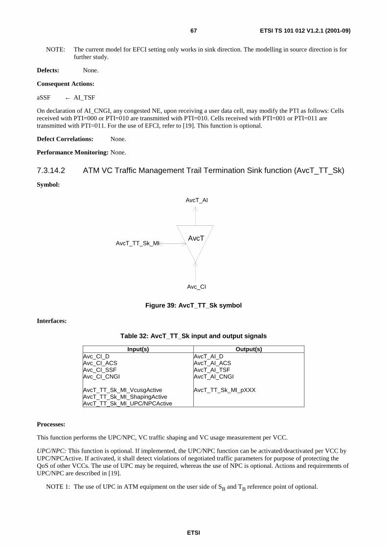
ETSI
ETSI TS 101 012 V1.2.1 (2001-09)67
NOTE: The current model for EFCI setting only works in sink direction. The modelling in source direction is for further study.
Defects: None.
Consequent Actions:
aSSF ← AI_TSF
On declaration of AI_CNGI, any congested NE, upon receiving a user data cell, may modify the PTI as follows: Cells received with PTI=000 or PTI=010 are transmitted with PTI=010. Cells received with PTI=001 or PTI=011 are transmitted with PTI=011. For the use of EFCI, refer to [19]. This function is optional.
Defect Correlations: None.
Performance Monitoring: None.
7.3.14.2 ATM VC Traffic Management Trail Termination Sink function (AvcT_TT_Sk)
Symbol:
AvcT
AvcT_AI
Avc_CI
AvcT_TT_Sk_MI
Figure 39: AvcT_TT_Sk symbol
Interfaces:
Table 32: AvcT_TT_Sk input and output signals
Input(s) Output(s) Avc_CI_D Avc_CI_ACS Avc_CI_SSF Avc_CI_CNGI AvcT_TT_Sk_MI_VcusgActive AvcT_TT_Sk_MI_ShapingActive AvcT_TT_Sk_MI_UPC/NPCActive
AvcT_AI_D AvcT_AI_ACS AvcT_AI_TSF AvcT_AI_CNGI AvcT_TT_Sk_MI_pXXX
Processes:
This function performs the UPC/NPC, VC traffic shaping and VC usage measurement per VCC.
UPC/NPC: This function is optional. If implemented, the UPC/NPC function can be activated/deactivated per VCC by UPC/NPCActive. If activated, it shall detect violations of negotiated traffic parameters for purpose of protecting the QoS of other VCCs. The use of UPC may be required, whereas the use of NPC is optional. Actions and requirements of UPC/NPC are described in [19].
NOTE 1: The use of UPC in ATM equipment on the user side of SB and TB reference point of optional.

ETSI
ETSI TS 101 012 V1.2.1 (2001-09)68
VC traffic shaping: This function is optional. If implemented, the shaping function can be activated/deactivated per VCC by ShapingActive. If activated, it shall perform traffic shaping according to [19].
NOTE 2: The VC traffic shaping function should not be simultaneously activated on both sink and source directions of the same VCC.
VC usage measurement: This function is optional. If enabled by VCusgActive, this function shall count the incoming cells on a VCC basis.
Defects:
Consequent Actions:
aCNGI ← CI_CNGI
aTSF ← CI_SSF
Defect Correlations:
Performance Monitoring:
The Performance Monitoring parameters are for further study. The parameters for the following functions need to be defined:
• VC usage measurement: Count for CLP = 0 + 1; Count for CLP = 0;
• UPC/NPC (tagged cell count): Count for CLP = 0 + 1; Count for CLP = 0.
7.3.14.3 ATM VC Traffic Management to ATM VC Adapt. Source function (AvcT/Avc_A_So)
Symbol:
AvcT/Avc
Avc_CI
AvcT_AI
Figure 40: AvcT/Avc_A_So symbol
Interfaces:
Table 33: AvcT/Avc_A_So input and output signals
Input(s) Output(s) Avc_CI_D Avc_CI_ACS Avc_CI_SSF Avc_CI_CNGI AvcT/Avc_A_So_MI_Active
AvcT_AI_D AvcT_AI_ACS AvcT_AI_TSF AvcT_AI_CNGI
NOTE: If activated by MI_Active, the input of this function is always connected to the AvcT/Avc_A_Sk function.
Processes: None.
Defects: None.

ETSI
ETSI TS 101 012 V1.2.1 (2001-09)69
Consequent Actions:
aTSF ← CI_SSF
aCNGI ← CI_CNGI
Defect Correlations: None.
Performance Monitoring: None.
7.3.14.4 ATM VC Traffic Management to ATM VC Adapt. Sink function (AvcT/Avc_A_Sk)
Symbol:
AvcT/Avc
Avc_CI
AvcT_AI
Figure 41: AvcT/Avc_A_Sk symbol
Interfaces:
Table 34: AvcT/Avc_A_Sk input and output signals
Input(s) Output(s)
NOTE: If activated by MI_Active, the output of this function is always connected to the AvcT/Avc_A_So function.
Processes: None.
Defects: None.
Consequent Actions:
aSSF ← AI_TSF
aCNGI ← AI_CNGI
Defect Correlations: None.
Performance Monitoring: None.

ETSI
ETSI TS 101 012 V1.2.1 (2001-09)70
7.3.15 ATM Virtual Channel Loopback Functions
7.3.15.1 ATM Virtual Channel Loopback Source Function (Avclb_TT_So)
Symbol:
Avc_CI
Avclb_RIAvcm_RI
Avclb_TT_So_MIAvclb
.
Figure 42: Avclb_TT_So symbol
Interfaces:
Table 35: Avclb_TT_So input and output signals
Input(s) Output(s) Avclb_RI_Lbresponse Avcm_RI_Lbresponse Avc_TT_So_MI_Lbdiscard Avc_TT_So_MI_Lbrequest
Avc_CI_D Avc_CI_ACS Avclb_RI_LBtimer Avcm_RI_LBtimer
Processes:
This function adds the following F5 loopback OAM cells to the Characteristic Information:
Loopback:
On Avc_MI_LBrequest, an F5 end-to-end loopback cell shall be generated with Loopback Indication set to "1". The LLID and Source ID contain the addresses of the loopback point, resp. of the source point. The default value of the Source ID filed is the all ONE's pattern. If the LLID address field contains an all ONE's pattern, it indicates the end points of the VC connection. If LBdiscard=true, an indication Avclb_RI_LBtimer shall be generated to start the timer at Avclb_TT_Sk. If LBdiscard=false, an indication Avcm_RI_LBtimer shall be generated to start the timer at Avcm_TT_Sk. Refer to [13], clause 9.2.2.1.3, network-to-endpoint loopback.
On Avc_MI_LBrequest, an F5 segment loopback cell shall be generated with Loopback Indication set to "1". The LLID and Source ID contain the addresses of the loopback point (single loopback technique), resp. of the source point. The default value of the Source ID field is the all ONE's pattern. If the LLID field contains an all ONE's pattern, it indicates all intermediate connecting points and the end points of the VC segment (multiple loopback technique). If LBdiscard=true, an indication Avclb_RI_LBtimer shall be generated to start the timer at Avclb_TT_Sk. If LBdiscard=false, an indication Avcm_RI_LBtimer shall be generated to start the timer at Avcm_TT_Sk. Refer to [13], clause 9.2.2.1.3, intra-domain loopback.
On Avclb_RI_LBresponse (LBdiscard=true) or Avcm_RI_LBresponse (LBdiscard=false), an F5 loopback cell identical to the cell passed through Avclb _RI_LBresponse/Avcm_RI_LBresponse shall be generated, but with Loopback Indication set to "0" and the LLID set to the CPID of the Loopback point. Refer to [13]. The time interval of sending consecutive segment or end-to-end Loopback cells shall be longer than 5 seconds.
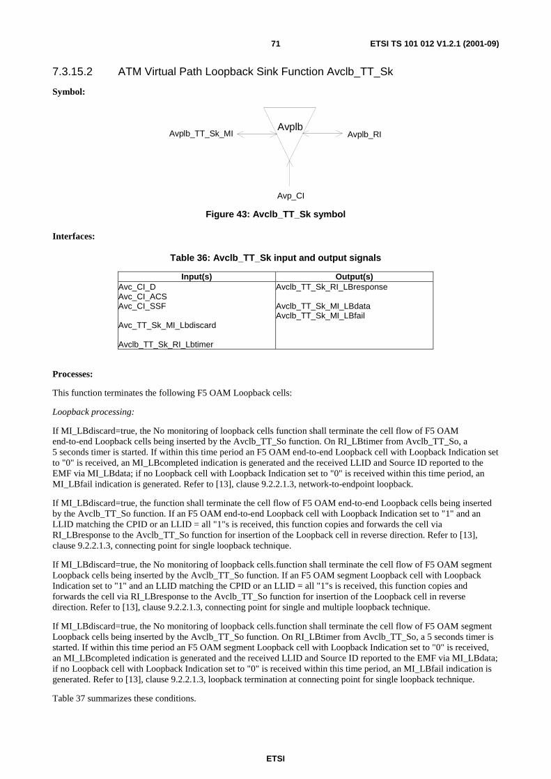
ETSI
ETSI TS 101 012 V1.2.1 (2001-09)71
7.3.15.2 ATM Virtual Path Loopback Sink Function Avclb_TT_Sk
Symbol:
Avplb
Avp_CI
Avplb_TT_Sk_MI Avplb_RI
Figure 43: Avclb_TT_Sk symbol
Interfaces:
Table 36: Avclb_TT_Sk input and output signals
Input(s) Output(s) Avc_CI_D Avc_CI_ACS Avc_CI_SSF Avc_TT_Sk_MI_Lbdiscard Avclb_TT_Sk_RI_Lbtimer
Avclb_TT_Sk_RI_LBresponse Avclb_TT_Sk_MI_LBdata Avclb_TT_Sk_MI_LBfail
Processes:
This function terminates the following F5 OAM Loopback cells:
Loopback processing:
If MI_LBdiscard=true, the No monitoring of loopback cells function shall terminate the cell flow of F5 OAM end-to-end Loopback cells being inserted by the Avclb_TT_So function. On RI_LBtimer from Avclb_TT_So, a 5 seconds timer is started. If within this time period an F5 OAM end-to-end Loopback cell with Loopback Indication set to "0" is received, an MI_LBcompleted indication is generated and the received LLID and Source ID reported to the EMF via MI_LBdata; if no Loopback cell with Loopback Indication set to "0" is received within this time period, an MI_LBfail indication is generated. Refer to [13], clause 9.2.2.1.3, network-to-endpoint loopback.
If MI_LBdiscard=true, the function shall terminate the cell flow of F5 OAM end-to-end Loopback cells being inserted by the Avclb_TT_So function. If an F5 OAM end-to-end Loopback cell with Loopback Indication set to "1" and an LLID matching the CPID or an LLID = all "1"s is received, this function copies and forwards the cell via RI_LBresponse to the Avclb_TT_So function for insertion of the Loopback cell in reverse direction. Refer to [13], clause 9.2.2.1.3, connecting point for single loopback technique.
If MI_LBdiscard=true, the No monitoring of loopback cells.function shall terminate the cell flow of F5 OAM segment Loopback cells being inserted by the Avclb_TT_So function. If an F5 OAM segment Loopback cell with Loopback Indication set to "1" and an LLID matching the CPID or an LLID = all "1"s is received, this function copies and forwards the cell via RI_LBresponse to the Avclb_TT_So function for insertion of the Loopback cell in reverse direction. Refer to [13], clause 9.2.2.1.3, connecting point for single and multiple loopback technique.
If MI_LBdiscard=true, the No monitoring of loopback cells.function shall terminate the cell flow of F5 OAM segment Loopback cells being inserted by the Avclb_TT_So function. On RI_LBtimer from Avclb_TT_So, a 5 seconds timer is started. If within this time period an F5 OAM segment Loopback cell with Loopback Indication set to "0" is received, an MI_LBcompleted indication is generated and the received LLID and Source ID reported to the EMF via MI_LBdata; if no Loopback cell with Loopback Indication set to "0" is received within this time period, an MI_LBfail indication is generated. Refer to [13], clause 9.2.2.1.3, loopback termination at connecting point for single loopback technique.
Table 37 summarizes these conditions.
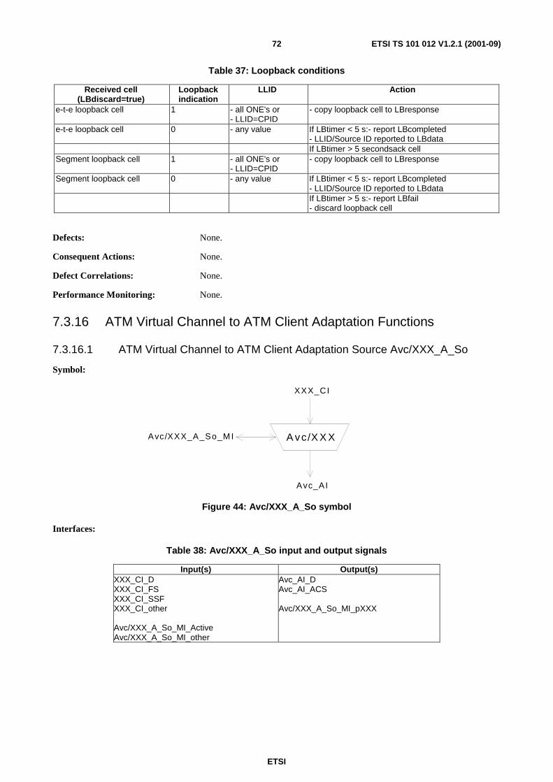
ETSI
ETSI TS 101 012 V1.2.1 (2001-09)72
Table 37: Loopback conditions
Received cell (LBdiscard=true)
Loopback indication
LLID Action
e-t-e loopback cell 1 - all ONE's or - LLID=CPID
- copy loopback cell to LBresponse
e-t-e loopback cell 0 - any value If LBtimer < 5 s:- report LBcompleted - LLID/Source ID reported to LBdata
If LBtimer > 5 secondsack cell Segment loopback cell 1 - all ONE's or
- LLID=CPID - copy loopback cell to LBresponse
Segment loopback cell 0 - any value If LBtimer < 5 s:- report LBcompleted - LLID/Source ID reported to LBdata
If LBtimer > 5 s:- report LBfail - discard loopback cell
Defects: None.
Consequent Actions: None.
Defect Correlations: None.
Performance Monitoring: None.
7.3.16 ATM Virtual Channel to ATM Client Adaptation Functions
7.3.16.1 ATM Virtual Channel to ATM Client Adaptation Source Avc/XXX_A_So
Symbol:
A vc/X X X
XXX_CI
Avc_AI
Avc/XXX_A_So_M I
Figure 44: Avc/XXX_A_So symbol
Interfaces:
Table 38: Avc/XXX_A_So input and output signals
Input(s) Output(s) XXX_CI_D XXX_CI_FS XXX_CI_SSF XXX_CI_other Avc/XXX_A_So_MI_Active Avc/XXX_A_So_MI_other
Avc_AI_D Avc_AI_ACS Avc/XXX_A_So_MI_pXXX

ETSI
ETSI TS 101 012 V1.2.1 (2001-09)73
Processes:
This function performs an AAL process for a given VCC in source direction. It is for further study. The following is a non-exhaustive list of possible candidates for payloads to be supported:
• CE 2 - 140 Mbit/s;
• CE n × 64 kbit/s;
• X.25, Frame Relay, HDLC;
• Internet Protocol;
• CBDS;
• N-ISDN interworking (BA, PRA);
• LAN (IEEE 802.x).
Defects: None.
Consequent Actions: None.
Defect Correlations: None.
Performance Monitoring: None.
7.3.16.2 ATM Virtual Channel to ATM Client Adaptation Sink Avc/XXX_A_Sk
Symbol:
A vc/X X X
XXX_CI
Avc_AI
Avc/XXX_A_Sk_M I
Figure 45: Avc/XXX_A_Sk symbol
Interfaces:
Table 39: Avc/XXX_A_Sk input and output signals
Input(s) Output(s)
Avc_AI_D Avc_AI_ACS Avc_AI_TSF Avc/XXX_A_Sk_MI_Active Avc/XXX_A_Sk_MI_other
XXX_CI_D XXX_CI_FS XXX_CI_SSF XXX_CI_other Avc/XXX_A_Sk_MI_pXXX

ETSI
ETSI TS 101 012 V1.2.1 (2001-09)74
Processes:
This function performs an AAL process for a given VCC in sink direction. It is for further study. The following is a non-exhaustive list of possible candidates for payloads to be supported:
• CE 2 - 140 Mbit/s;
• CE n × 64 kbit/s;
• X.25, Frame Relay, HDLC;
• Internet Protocol;
• CBDS;
• N-ISDN interworking (BA, PRA);
• LAN (IEEE 802.x).
Defects: None.
Consequent Actions: None.
Defect Correlations: None.
Performance Monitoring: None.
7.4 xDSL Transmission Functions
7.4.1 ADSL
7.4.1.1 ADSL PMD layer functions
ADSLpmd_TT
ADSLpmd_TT
ADSLpmd/s_A
ADSLpmd_CI
ADSLpmd/s_A
ADSLpmd_AI
ADSLpmd/s_A_Sk_MI
ADSLpmd_TT_Sk_MI
ADSLpmd_TT_RI
ADSLpmd/s_A_RI
ADSL PMD Layer Characteristic Information ADSLpmd_CI
Continuous analogue ADSL line signal.
ADSL PMD Layer Adaptation Information ADSLpmd_AI
Sequence of discrete samples representing the digitized ADSL line signal.

ETSI
ETSI TS 101 012 V1.2.1 (2001-09)75
7.4.1.2 ADSL PMD Layer Trail Termination Source Function (ADSLpmd _TT_So)
Reference: [15], clauses 7.11 and 8.11.
Symbol:
ADSLpmd_TT
ADSLpmd_CI
ADSLpmd_AI
Interfaces:
Input(s) Output(s) ADSLpmd_AI_D (data samples) ADSLpmd_AI_CLK (sample clock 2,208 MHz)
ADSLpmd_CI_D (analogue signal)
Processes:
Digital-to-Analogue Conversion of the ADSL line signal.
Defects: None.
Consequent Actions: None.
Defect Correlations: None.
Performance Monitoring: None.

ETSI
ETSI TS 101 012 V1.2.1 (2001-09)76
7.4.1.3 ADSL PMD Layer Trail Termination Sink Function ADSLpmd _TT_Sk
Reference: [15], clauses 7.11 and 8.11.
Symbol:
ADSLpmd_TT
ADSLpmd_CI
ADSLpmd_AI
ADSLpmd_TT_Sk_MI
ADSLpmd_TT_RI
Interfaces:
Input(s) Output(s) ADSLpmd_CI_D (analogue signal) ADSLpmd_TT_Sk_MI_LineActivated
ADSLpmd_AI_D (data samples) ADSLpmd_AI_CLK (sample clock 2,208 MHz) ADSLpmd_AI_TSF (trail signal fail) ADSLpmd_TT_Sk_MI_cLOS ADSLpmd_TT_Sk_MI_pLOS ADSLpmd_TT_RI_LOS
Processes:
Analogue-to-Digital conversion of the ADSL line signal.
LOS detection by estimation of the incoming signal regarding to pilot tone reference power.
Defects:
dLOS: A pilot tone reference power shall be established by averaging the ADSL pilot tone power for 0,1 s after the start of steady state data transmission (i.e. after initialization), and a threshold shall be set at 6 dB below the reference power. A dLOS defect occurs when the level of the received ADSL pilot tone power, averaged over a 0,1 s period, is lower than the threshold, and terminates when this level, measured in the same way, is at or above the threshold;
Consequent Actions:
aTSF ← dLOS
aRDI ← dLOS
Defect Correlations:
cLOS ← dLOS
Performance Monitoring: pLOS: Counter of seconds with at least one occurrence of a dLOS defect.

ETSI
ETSI TS 101 012 V1.2.1 (2001-09)77
7.4.1.4 ADSL PMD Layer to Section Adaptation Source Function (ADSLpmd/s_A_So)
Reference: [15], clauses 7.6.3 to 7.12 and 8.7 to 8.12.
Symbol:
ADSLpmd/s_A
ADSLs_CI
ADSLpmd_AI
Processes:
Section data coming from the interleaved buffer are re-ordered in their sequence according to the interleaving mechanism.
After that the whole ADSL frame data bits are distributed onto the different sub-carriers according to the tone ordering algorithm (i.e. starting with fast buffer data are assigned to the carrier with lowest bit transportation capacity).
Every sub-carrier has an own constellation encoder with a specific range of constellation points that is adjusted during line activation. After constellation encoding the resulting vector of complex constellations from all sub-carriers is transformed into a time domain sequence of discrete samples by the Inverse Fast Fourier Transform (IFFT) algorithm.
Following 68 ADSL section frames a special constellation vector is processed by IFFT that indicates superframe boundaries and is referred to as synchronization symbol.
Finally the time domain signal is extended by a cyclic prefix that is used to detect symbol boundaries at the receiver.
Interfaces:
Input(s) Output(s) ADSLs_CI_D (FEC output data) ADSLs_CI_CLK (FEC output frame bit clock) ADSLs_CI_FCLK (FEC output frame clock) ADSLs_CI_SCLK (superframe clock)
ADSLpmd_AI_D (data samples) ADSLpmd_AI_CLK (sample clock)
Defects: None.
Consequent Actions: None.
Defect Correlations: None.
Performance Monitoring: None.

ETSI
ETSI TS 101 012 V1.2.1 (2001-09)78
7.4.1.5 ADSL PMD Layer to Section Adaptation Sink Function ADSLpmd/s_A_Sk
Reference: [15], clauses 7.6.3 to 7.12 and 8.7 to 8.12.
Symbol:
ADSLpmd/s_A
ADSLs_CI
ADSLpmd_AI
ADSLpmd/s_A_Sk_MI
ADSLpmd/s_A_RI
Processes:
This function establishes symbol synchronization by searching for the time-domain cyclic prefix of each symbol. After that the cyclic prefix is removed.
The remaining time-domain signal is processed by the Fast Fourier Transform (FFT) algorithm. This results in complex constellation values for the different QAM sub-carriers. After constellation decoding a related bit-pair for every carrier becomes available. The carrier specific bit-pairs are composed into an overall bitstream that is compared with the sync symbol bitstream. In this way synchronization symbols indicate that superframe boundaries are detected.
After establishment of superframe synchronization all data symbols between synchronization symbols are processed by the FFT algorithm in the same way, however the carrier specific constellation decoders use the range of constellation points that was adjusted during the activation procedure. This results in different bitstream length for different sub-carriers after constellation decoding.
Then the original ADSL section frame is composed from the various carrier specific streams by the tone reordering procedure. Interleaving buffer data are re-ordered in their sequence according to the interleaving algorithm.
Interfaces:
Input(s) Output(s) ADSLpmd_AI_D (data samples) ADSLpmd_AI_CLK (sample clock) ADSLpmd_AI_TSF
ADSLs_CI_D (FEC input data) ADSLs_CI_CLK (FEC input frame bit clock) ADSLs_CI_FCLK (FEC input frame clock) ADSLs_CI_SCLK (superframe clock) ADSLs_CI_SSF (server signal fail) ADSLpmd/s_A_Sk_MI_cLOF ADSLpmd/s_A_Sk_RI_LOF
Defects:
dLOF: A dLOF defect occurs when the contents of two consecutively received ADSL synchronization symbols do not correlate with the expected content over a subset of the tones. A dLOF defect terminates when the content of two consecutively received ADSL synchronization symbols correlate with the expected contents over the same subset of the tones. The correlation method, the selected subset of the tones, and the threshold for declaring the dLOF defect condition are implementation discretionary;
Consequent Actions:
aSSF ← dLOF or aTSF
aRDI ← dLOF or aTSF
Defect Correlations:
cLOF ← dLOF and not aTSF
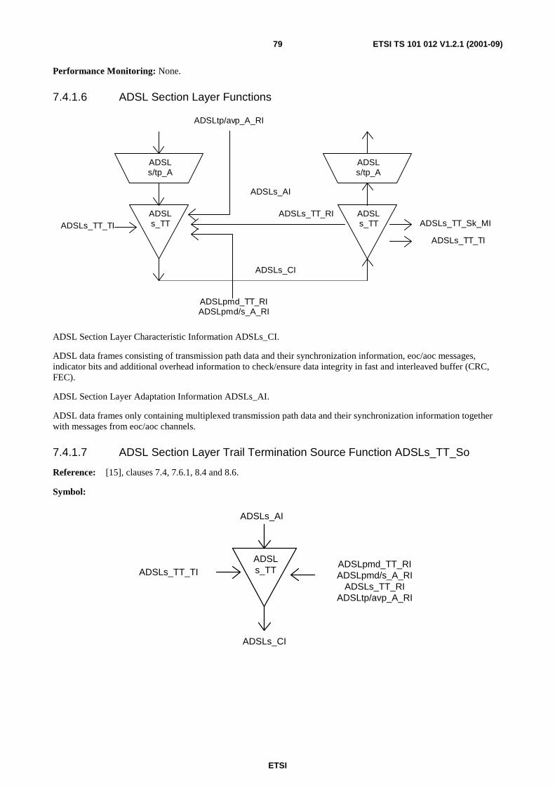
ETSI
ETSI TS 101 012 V1.2.1 (2001-09)79
Performance Monitoring: None.
7.4.1.6 ADSL Section Layer Functions
ADSLs_TT
ADSLs_TT
ADSLs/tp_A
ADSLs_CI
ADSLs/tp_A
ADSLs_AI
ADSLs_TT_TI
ADSLpmd_TT_RIADSLpmd/s_A_RI
ADSLs_TT_Sk_MI
ADSLs_TT_TI
ADSLs_TT_RI
ADSLtp/avp_A_RI
ADSL Section Layer Characteristic Information ADSLs_CI.
ADSL data frames consisting of transmission path data and their synchronization information, eoc/aoc messages, indicator bits and additional overhead information to check/ensure data integrity in fast and interleaved buffer (CRC, FEC).
ADSL Section Layer Adaptation Information ADSLs_AI.
ADSL data frames only containing multiplexed transmission path data and their synchronization information together with messages from eoc/aoc channels.
7.4.1.7 ADSL Section Layer Trail Termination Source Function ADSLs_TT_So
Reference: [15], clauses 7.4, 7.6.1, 8.4 and 8.6.
Symbol:
ADSLs_TT
ADSLs_CI
ADSLs_AI
ADSLs_TT_TIADSLpmd_TT_RIADSLpmd/s_A_RI
ADSLs_TT_RIADSLtp/avp_A_RI

ETSI
ETSI TS 101 012 V1.2.1 (2001-09)80
Interfaces:
Input(s) Output(s) ADSLs_AI_D (mux frame data) ADSLs_AI_CLK (mux data frame bit clock) ADSLs_AI_FCLK (mux data frame clock) ADSLs_AI_SCLK (mux superframe clock) ADSLs_TT_TI_NTR (network timing reference) ADSLs_TT_RI_CRC-I ADSLs_TT_RI_FEC-I ADSLs_TT_RI_CRC-F ADSLs_TT_RI_FEC-F ADSLpmd_TT_RI_LOS ADSLpmd/s_A_RI_LOF ADSLtp/Avp_A_RI_NCD-I ADSLtp/Avp_A_RI_NCD-F ADSLtp/Avp_A_RI_HEC-I ADSLtp/Avp_A_RI_HEC-F
ADSLs_CI_D (FEC output frame data) ADSLs_CI_CLK (FEC output frame bit clock) ADSLs_CI_FCLK (FEC output frame clock) ADSLs_CI_SCLK (superframe clock)
Processes:
Indicator bit control:
ib8: The febe-I indicator is controlled by ADSLs_TT_RI_CRC-I and is reported once per superframe. The febe-I indicator shall be coded 1 to indicate that no ADSLs_TT_RI_CRC-I notification occurred during the previous superframe otherwise it shall be coded 0.
ib9: The fecc-I indicator is controlled by ADSLs_TT_RI_FEC-I and is reported once per superframe. The fecc-I indicator shall be coded 1 to indicate that no ADSLs_TT_RI_FEC-I notification occurred during the previous superframe otherwise it shall be coded 0.
ib10: The febe-F indicator is controlled by ADSLs_TT_RI_CRC-F and is reported once per superframe. The febe-F indicator shall be coded 1 to indicate that no ADSLs_TT_RI_CRC-F notification occurred during the previous superframe otherwise it shall be coded 0.
ib11: The fecc-F indicator is controlled by ADSLs_TT_RI_FEC-F and is reported once per superframe. The fecc-F indicator shall be coded 1 to indicate that no ADSLs_TT_RI_FEC-F notification occurred during the previous superframe otherwise it shall be coded 0.
ib12: The los indicator is controlled by ADSLpmd_TT_RI_LOS and is reported once per superframe. The los indicator shall be coded 1 to indicate that no ADSLs_TT_RI_LOS notification occurred during the previous superframe. If ADSLpmd_TT_RI_LOS notification occurred the los indicator shall be coded 0 for 6 consecutive superframes.
ib13: The rdi indicator is controlled by ADSLpmd/s_A_RI_LOF and is reported once per superframe. The rdi indicator shall be coded 1 to indicate that no ADSLpmd/s_A_RI_RDI notification occurred during the previous superframe otherwise it shall be coded 0.
ib14: The ncd-I indicator is controlled by ADSLtp/Avp_A_RI_NCD-I and is reported once per superframe. The ncd-I indicator shall be coded 1 to indicate that no ADSLtp/Avp_A_RI_NCD-I notification occurred during the previous superframe otherwise it shall be coded 0.
ib15: The ncd-F indicator is controlled by ADSLtp/Avp_A_RI_NCD-F and is reported once per superframe. The ncd-F indicator shall be coded 1 to indicate that no ADSLtp/Avp_A_RI_NCD-F notification occurred during the previous superframe otherwise it shall be coded 0.
ib16: The hec-I indicator is controlled by ADSLtp/Avp_A_RI_HEC-I and is reported once per superframe. The hec-I indicator shall be coded 1 to indicate that no ADSLtp/Avp_A_RI_HEC-I notification occurred during the previous superframe otherwise it shall be coded 0.
ib17: The hec-F indicator is controlled by ADSLtp/Avp_A_RI_HEC-F and is reported once per superframe. The hec-F indicator shall be coded 1 to indicate that no ADSLtp/Avp_A_RI_HEC-F notification occurred during the previous superframe otherwise it shall be coded 0.
ib20..23: Representing the change in phase offset between the input NTR and LTR from the previous superframe to the present one.

ETSI
ETSI TS 101 012 V1.2.1 (2001-09)81
Processing of FastBuffer information:
Insertion of fast byte information:
ADSL Frame Number
Fast Byte Content
Full overhead mode Reduced overhead mode with separate fast and sync
byte
Reduced overhead mode with merged fast and sync
bytes in fast buffer 0 CRC for fast buffer data of the previous superframe 1 Indicator bits ib0-7 34 Indicator bits ib8-15 35 Indicator bits ib16-23
CRC checksum calculation over all data transported in fast buffer in an ADSL superframe (i.e. 68 ADSL frames)
Calculation of FEC parity bytes for fast data buffer of one ADSL frame and appending this information to the fast buffer
Processing of Interleaved Buffer information:
Insertion of sync byte information:
ADSL Frame Number
Sync Byte Content
Full overhead mode Reduced overhead mode with separate fast and sync
byte
Reduced overhead mode with merged fast and sync bytes in interleaved buffer
0 CRC for interleaved buffer data of the previous superframe 1 Indicator bits ib0-7 34 Indicator bits ib8-15 35
- -
Indicator bits ib16-23
CRC checksum calculation over all data transported in interleaved buffer in an ADSL superframe (i.e. 68 ADSL frames)
Calculation of FEC parity bytes for interleaved data buffer of 1 to 64 ADSL frame(s) and appending this information to the interleaved buffer
Defects: None.
Consequent Actions: None.
Defect Correlations: None.
Performance Monitoring: None.

ETSI
ETSI TS 101 012 V1.2.1 (2001-09)82
7.4.1.8 ADSL Section Layer Trail Termination Sink Function ADSLs_TT_Sk
Reference: [15], clauses 7.4, 7.6.1, 8.4 and 8.6.
Symbol:
ADSLs_TT
ADSLs_CI
ADSLs_AI
ADSLs_TT_Sk_MI
ADSLs_TT_TIADSLs_TT_RI
Interfaces:
Input(s) Output(s) ADSLs_CI_D (FEC input frame data) ADSLs_CI_CLK (FEC input frame bit clock) ADSLs_CI_FCLK (FEC input frame clock) ADSLs_CI_SCLK (superframe clock) ADSLs_CI_SSF (server signal fail)
ADSLs_AI_D (mux frame data) ADSLs_AI_CLK (mux data frame bit clock) ADSLs_AI_FCLK (mux data frame clock) ADSLs_AI_SCLK (superframe clock) ADSLs_AI_TSF (trail signal fail) ADSLs_TT_TI_NTR (network timing reference) ADSLs_TT_Sk_MI_cFLOS ADSLs_TT_Sk_MI_cFLOF ADSLs_TT_Sk_MI_cFLCD-I ADSLs_TT_Sk_MI_cFLCD-F ADSLs_TT_Sk_MI_pCRC-I ADSLs_TT_Sk_MI_pCRC-F ADSLs_TT_Sk_MI_pFEC-I ADSLs_TT_Sk_MI_pFEC-F ADSLs_TT_Sk_MI_pFECS ADSLs_TT_Sk_MI_pES ADSLs_TT_Sk_MI_pSES ADSLs_TT_Sk_MI_pUAS ADSLs_TT_Sk_MI_pFEBE-I ADSLs_TT_Sk_MI_pFEBE-F ADSLs_TT_Sk_MI_pFFEC-I ADSLs_TT_Sk_MI_pFFEC-F ADSLs_TT_Sk_MI_pFFECS ADSLs_TT_Sk_MI_pFES ADSLs_TT_Sk_MI_pFSES ADSLs_TT_Sk_MI_pFLOS ADSLs_TT_Sk_MI_pFUAS ADSLs_TT_RI_CRC-I ADSLs_TT_RI_FEC-I ADSLs_TT_RI_CRC-F ADSLs_TT_RI_FEC-F
Processes:
Processing of FastBuffer information:
FEC parity byte check for fast data buffer of every ADSL frame
CRC checksum processing over all data transported in fast buffer in an ADSL superframe
Extraction of fast byte information (see clause 7.4.1.7)

ETSI
ETSI TS 101 012 V1.2.1 (2001-09)83
Processing of Interleaved Buffer information:
FEC parity byte check for interleaved data buffer of 1 to 64 ADSL frame(s)
CRC checksum processing over all data transported in interleaved buffer in an ADSL superframe
Extraction of sync byte information: (see clause 7.4.1.7)
Anomalies:
Forward Error Correction (fec-I) anomaly: A fec-I anomaly occurs when a received FEC code for the interleaved data stream indicates that errors have been corrected.
Forward Error Correction (fec-F) anomaly: A fec-F anomaly occurs when a received FEC code for the fast data stream indicates that errors have been corrected.
Cyclical Redundancy Check (crc-I) anomaly: A crc-I anomaly occurs when a received CRC-8 code for the interleaved data stream is not identical to the corresponding locally generated code.
Cyclical Redundancy Check (crc-F) anomaly: A crc-F anomaly occurs when a received CRC-8 code for the fast data stream is not identical to the corresponding locally generated code.
Far-end Forward Error Correction (ffec-I) anomaly: An ffec-I anomaly is a fec-I anomaly detected at the far end. A ffec-I anomaly occurs when a received fecc-I indicator is set to 0. A ffec-I anomaly terminates when a received fecc-I indicator is set to 1.
Far-end Forward Error Correction (ffec-F) anomaly: An ffec-F anomaly is a fec-F anomaly detected at the far end. The ffec-F anomaly will occur and terminate in the same way as the febe-I anomaly.
Far-end Block Error (febe-I) anomaly: A febe-I anomaly is a crc-I anomaly detected at the far-end. A febe-I anomaly occurs when a received febe-I indicator is set to 0. A febe-I anomaly terminates when a received febe-I indicator is set to 1.
Far-end Block Error (febe-F) anomaly: A febe-F anomaly is a crc-F anomaly detected at the far-end. The febe-F anomaly will occur and terminate in the same way as the febe-I anomaly.
Far-end No Cell Delineation (fncd-I) anomaly: A fncd-I anomaly is a ncd-I anomaly detected at the far-end. An fncd-I anomaly occurs immediately after ATU start-up and terminates if a received ncd-I indicator is coded 1.
Far-end No Cell Delineation (fncd-F) anomaly: A fncd-F anomaly is a ncd-F anomaly detected at the far-end. An fncd-F anomaly occurs immediately after ATU start-up and terminates if a received ncd-F indicator is coded 1.
Far-end Out of Cell Delineation (focd-I) anomaly: A focd-I anomaly is an ocd-I anomaly detected at the far-end. A focd-I anomaly occurs if no fncd-I anomaly is present and a received ncd-I indicator is coded 0. A focd-I anomaly terminates if a received ncd-I indicator is coded 1.
Far-end Out of Cell Delineation (focd-F) anomaly: A focd-F anomaly is an ocd-F anomaly detected at the far-end. A focd-F anomaly occurs if no fncd-F anomaly is present and a received ncd-F indicator is coded 0. A focd-F anomaly terminates if a received ncd-F indicator is coded 1.
Far-end Header Error Check (fhec-I) anomaly: A fhec-I anomaly is a hec-I anomaly detected at the far end. A fhec-I anomaly occurs when a received hec-I indicator is set to 0. A fhec-I anomaly terminates when a received hec-I indicator is set to 1.
Far-end Header Error Check (fhec-F) anomaly: A fhec-F anomaly is a hec-F anomaly detected at the far end. The fhec-F anomaly will occur and terminate in the same way as the fhec-I anomaly.
Defects:
dFLOS: A far-end LOS defect is a LOS defect detected at the far-end. A dLOS defect occurs when 4 or more out of 6 contiguous los indicators are received set to 0. A far-end LOS defect terminates when 4 or more out of 6 contiguously received los indicators are set to 1.
dFLOF: A far-end LOF defect is a LOF defect detected at the far end. A dFLOF defect occurs when a received rdi indicator is set to 0. An FLOF defect terminates when a received rdi indicator is set to 1.

ETSI
ETSI TS 101 012 V1.2.1 (2001-09)84
dFLCD-I: A far-end LCD-I defect is a dLCD-I defect detected at the far-end. A dFLCD-I defect occurs when a focd-I anomaly is present and 4 consecutively received ncd-I indicators are coded 0 and no dLOS defect is present. A dFLCD-I defect terminates if 4 consecutively received ncd-I indicators are coded 1.
dFLCD-F: A far-end LCD-F defect is a dLCD-F defect detected at the far-end. A dFLCD-F defect occurs when a focd-F anomaly is present and 4 consecutively received ncd-F indicators are coded 0 and no dLOS defect is present. A dFLCD-F defect terminates if 4 consecutively received ncd-F indicators are coded 1.
Consequent Actions:
aTSF ← aSSF aREI_CRC-I ← FEC-I anomaly aREI_CRC-F ← FEC-F anomaly aREI_FEC-I ← CRC-I anomaly aREI_FEC-F ← CRC-F anomaly
Defect Correlations:
cFLOS ← dFLOS cFLOF ← dFLOF cFLCD-I ← dFLCD-I cFLCD-F ← dFLCD-F
Performance Monitoring:
pCRC-I: Counter of CRC-8 anomalies in the interleaved data buffer (subject to inhibiting - see pUAS).
pCRC-F: Counter of CRC-8 anomalies in the fast data buffer (subject to inhibiting - see pUAS).
pFEC-I: Counter of FEC codeword corrections in the interleaved data buffer (subject to inhibiting - see pUAS).
pFEC-F: Counter of FEC codeword corrections in the fast data buffer (subject to inhibiting - see pUAS).
pFECS: Counter of second intervals with one or more fec anomalies.
pES: Counter of second intervals with one or more CRC-8 anomalies, or one or more aSSF events.
pSES: Counter of second intervals with x=18 or more CRC-8 anomalies or one or more aSSF events.
pUAS: Counter of second intervals for which the ADSL line is unavailable. The ADSL line becomes unavailable at the onset of 10 contiguous SESs. The 10 SESs are included in unavailable time. Once unavailable, the ADSL line becomes available at the onset of 10 contiguous seconds with no SESs. The 10 seconds with no SESs are excluded from unavailable time. Some parameter counts are inhibited during unavailability.
pFEBE-I: Counter of febe-I anomalies in the interleaved data buffer (subject to inhibiting - see pFUAS).
pFEBE-F: Counter of febe-F anomalies in the fast data buffer (subject to inhibiting - see pFUAS).
pFFEC-I: Counter of ffec-I in the interleaved data buffer (subject to inhibiting - see pFUAS).
pFFEC-F: Counter of ffec-F in the fast data buffer (subject to inhibiting - see pFUAS).
pFFECS: Counter of second intervals with one or more ffec anomalies.
pFES: Counter of second intervals with one or more febe anomalies, or one or more dFLOS or dFLOF defects.
pFSES: Counter of second intervals with x=18 or more febe anomalies, or one or more dFLOS or dFLOF defects.
pFLOS Counter of second intervals containing one or more dFLOS defects.
pFUAS: Counter of second intervals for which the far-end ADSL line is unavailable. The far-end ADSL line becomes unavailable at the onset of 10 contiguous FSESs. The 10 FSESs are included in unavailable time. Once unavailable, the far-end ADSL line becomes available at the onset of 10 contiguous seconds with no FSESs. The 10 seconds with no FSESs are excluded from unavailable time. Some parameter counts are inhibited during unavailability.

ETSI
ETSI TS 101 012 V1.2.1 (2001-09)85
7.4.1.9 ADSL Section Layer to TP Adaptation Source Function ADSLs/tp _A_So
Reference: [15], clauses 7.4.1, 7.4.2, 8.4.1 and 8.4.2.
Symbol:
ADSLs/tp_A
ADSLtp_CI
ADSLs_AI
FastData
InterleavedData
EOCData
AOCData
Processes:
Up to four simplex (AS0..3 - only in downstream direction) and three duplex (LS0..2) transmission paths will be synchronized to the 4 kHz ADSL data frame rate by the synchronization control mechanism (using synchronization control byte and the AEX and LEX bytes). That mechanism is not necessary for synchronous data streams in reduced overhead framing mode.
The synchronous data streams are then multiplexed into two separate data buffers (fast and interleaved).
Insertion of fast byte information:
ADSL Frame Number
Fast Byte Content
Full overhead mode Reduced overhead mode with separate fast and sync
byte
Reduced overhead mode with merged fast and sync
bytes in fast buffer 4n+2, 4n+3 n=0..7,9..16
Eoc messages (2 octets long beginning with even numbered frames) or sync messages
4n, 4n+1 n=1..16
Eoc messages (2 octets long beginning with even numbered frames) or sync messages
Aoc messages
Insertion of sync byte information:
ADSL Frame Number
Sync Byte Content
Full overhead mode Reduced overhead mode with separate fast and sync
byte
Reduced overhead mode with merged fast and sync bytes in interleaved buffer
1 - 34 - 35 - 4n+2, 4n+3 n=0..7,9..16
Eoc messages (2 octets long beginning with even numbered frames) or sync messages
4n, 4n+1 n=1..16
Sync messages or aoc messages
Aoc messages
Aoc messages

ETSI
ETSI TS 101 012 V1.2.1 (2001-09)86
Interfaces:
Input(s) Output(s) ADSLtp(i)_CI_D (i: AS0..3, LS0..2)) ADSLtp(i)_CI_CLK (TP bit clock) ADSLtp_CI_EOC (eoc message) ADSLtp_CI_AOC (aoc message)
ADSLs_AI_D (mux frame data) ADSLs_AI_CLK (mux data frame bit clock) ADSLs_AI_FCLK (mux data frame clock) ADSLs_AI_SCLK (mux superframe clock)
Defects: None.
Consequent Actions: None.
Defect Correlations: None.
Performance Monitoring: None.
7.4.1.10 ADSL Section Layer to TP Adaptation Sink Function ADSLs/tp_A_Sk
Reference: [15], clauses 7.4.1, 7.4.2, 8.4.1 and 8.4.2.
Symbol:
ADSLs/tp_A
ADSLtp_CI
ADSLs_AI
FastData
InterleavedData
EOCData
AOCData
Processes:
The data received from the fast and interleaved data buffer are reassigned to the particular ADSL transmission paths.
The information from the synchronization control byte in companion with the AEX and LEX bytes is used to recover the original frequency of the path signal.. That mechanism is not necessary for synchronous data streams in reduced overhead framing mode.
Extraction of fast byte information: see clause 7.4.1.9
Extraction of sync byte information: see clause 7.4.1.9
Interfaces:
Input(s) Output(s) ADSLs_AI_D (mux frame data) ADSLs_AI_CLK (mux data frame bit clock) ADSLs_AI_FCLK (mux data frame clock) ADSLs_AI_SCLK (superframe clock) ADSLs_AI_TSF (trail signal fail)
ADSLtp(i)_CI_D (i: AS0..3, LS0..2)) ADSLtp(i)_CI_CLK (TP bit clock) ADSLtp(i)_CI_SSF (server signal fail) ADSLtp_CI_EOC (eoc message) ADSLtp_CI_AOC (aoc message)
Defects: None.
Consequent Actions: None.
Defect Correlations: aSSF ← aTSF
Performance Monitoring: None.

ETSI
ETSI TS 101 012 V1.2.1 (2001-09)87
7.4.1.11 ADSL TP Layer Functions
ADSLtp_TT
ADSLtp_TT
ADSLtp/Avp_A
ADSLtp_CI
ADSLtp/Avp_A
ADSLtp_AI
ADSLtp/Avp_A_RI
ADSLtp/Avp_A_Sk_MI
ADSLtp/Avp_A_So_MI
ADSLtp_C
ADSLtp_C ADSLtp_C_MIADSLtp_C_MI
ADSL TP Layer Characteristic Information ADSLtp_CI.
ADSL transmission path signal AS0..AS3 (only downstream) and LS0..LS2.
ADSL TP Layer Adaptation Information ADSLtp_AI.
Identical with ADSLtp_CI.
7.4.1.12 ADSL TP Layer Connection Function ADSLtp _C
Reference: [15], clauses 6.1 and 6.2.
Symbol:
ADSLtp_CI
ADSLtp_CI
ADSLtp_C
ADSLtp_C_MI
Interfaces:
Input(s) Output(s) ADSLtp(i)_CI_D (i: AS0..3, LS0..2)) ADSLtp(i)_CI_CLK (TP bit clock) ADSLtp(i)_CI_SSF (server signal fail) ADSLtp_C_MI_Connect (TP connection control)
ADSLtp(i)_CI_D (i: AS0..3, LS0..2)) ADSLtp(i)_CI_CLK (TP bit clock) ADSLtp(i)_CI_SSF (server signal fail)

ETSI
ETSI TS 101 012 V1.2.1 (2001-09)88
Processes:
This function connects the ADSL transmission paths with the fast and interleaved ADSL transmission channel within ADSL section layer.
The matrix connection is defined as an 2-port, i.e. the set of input and output ports is divided into two subsets, each containing both input and output ports.
Symbol:
FastChannel
AS0..3
InterleavedChannel
LS0..2
Input AS0..3 LS0..2 Fast Channel Interleaved Channel
AS0..3 - - Downstream Downstream LS0..2 - - + +
Fast Channel Downstream + - -
Output
Interleaved Channel
Downstream + - -
Defects: None.
Consequent Actions: None.
Defect Correlations: None.
Performance Monitoring: None.
7.4.1.13 ADSL TP Layer Trail Termination Source Function ADSLtp _TT_So
Reference:
Symbol:
ADSLtp_TT
ADSLtp_CI
ADSLtp_AI

ETSI
ETSI TS 101 012 V1.2.1 (2001-09)89
Interfaces:
Input(s) Output(s) ADSLtp(i)_AI_D (i: AS0..3, LS0..2)) ADSLtp(i)_AI_CLK (TP bit clock)
ADSLtp(i)_CI_D (i: AS0..3, LS0..2)) ADSLtp(i)_CI_CLK (TP bit clock)
Processes: None.
Defects: None.
Consequent Actions: None.
Defect Correlations: None.
Performance Monitoring: None.
7.4.1.14 ADSL TP Layer Trail Termination Sink Function ADSLtp _TT_Sk
Reference:
Symbol:
ADSLtp_TT
ADSLtp_CI
ADSLtp_AI
Interfaces:
Input(s) Output(s) ADSLtp(i)_CI_D (i: AS0..3, LS0..2)) ADSLtp(i)_CI_CLK (TP bit clock) ADSLtp(i)_CI_SSF (server signal fail)
ADSLtp(i)_AI_D (i: AS0..3, LS0..2)) ADSLtp(i)_AI_CLK (TP bit clock) ADSLtp(i)_TSF (trail signal fail)
Processes: None.
Defects: None.
Consequent Actions: aTSF ← aSSF
Defect Correlations: None.
Performance Monitoring: None.
7.4.2 VDSL
Application specific TPS-TC layer specifications for VDSL are contained in reference [24].
7.4.3 SDSL
Application specific TPS-TC layer specifications for SDSL are contained in annex A of reference [23].

ETSI
ETSI TS 101 012 V1.2.1 (2001-09)90
7.5 ATM25,6 UNI Transmission Functions
7.5.1 ATM25,6 PMD Layer Functions
ATM25 pmd_TT
ATM25 pmd_TT
ATM25 pmd/s_A
ATM25pmd_CI
ATM25 pmd/s_A
ATM25pmd_AI
ATM25pmd/s_A_MI
ATM25,6 PMD Layer Characteristic Information ATM25pmd_CI.
Symmetrical electrical digital signal of defined amplitude, bit rate (32 Mbit/s) and pulse shape as defined in af-phy-0040.000 [6].
ATM25,6 PMD Layer Adaptation Information ATM25pmd_AI.
Logical bitstream with co-directional bit timing.
7.5.1.1 ATM25,6 PMD Layer Trail Termination Source Function (ATM25pmd _TT_So)
Reference: [6], clause 2.
Symbol:
ATM25 pmd_TT
ATM25pmd_CI
ATM25pmd_AI
Interfaces:
Input(s) Output(s) ATM25pmd_AI_D (data bits) ATM25pmd_AI_CLK (32 MHz clock)
ATM25pmd_CI_D (line signal)
Processes:
This function converts a logical bit stream into a symmetrical electrical signal according to af-phy-0040.000 [6].
Defects: None.
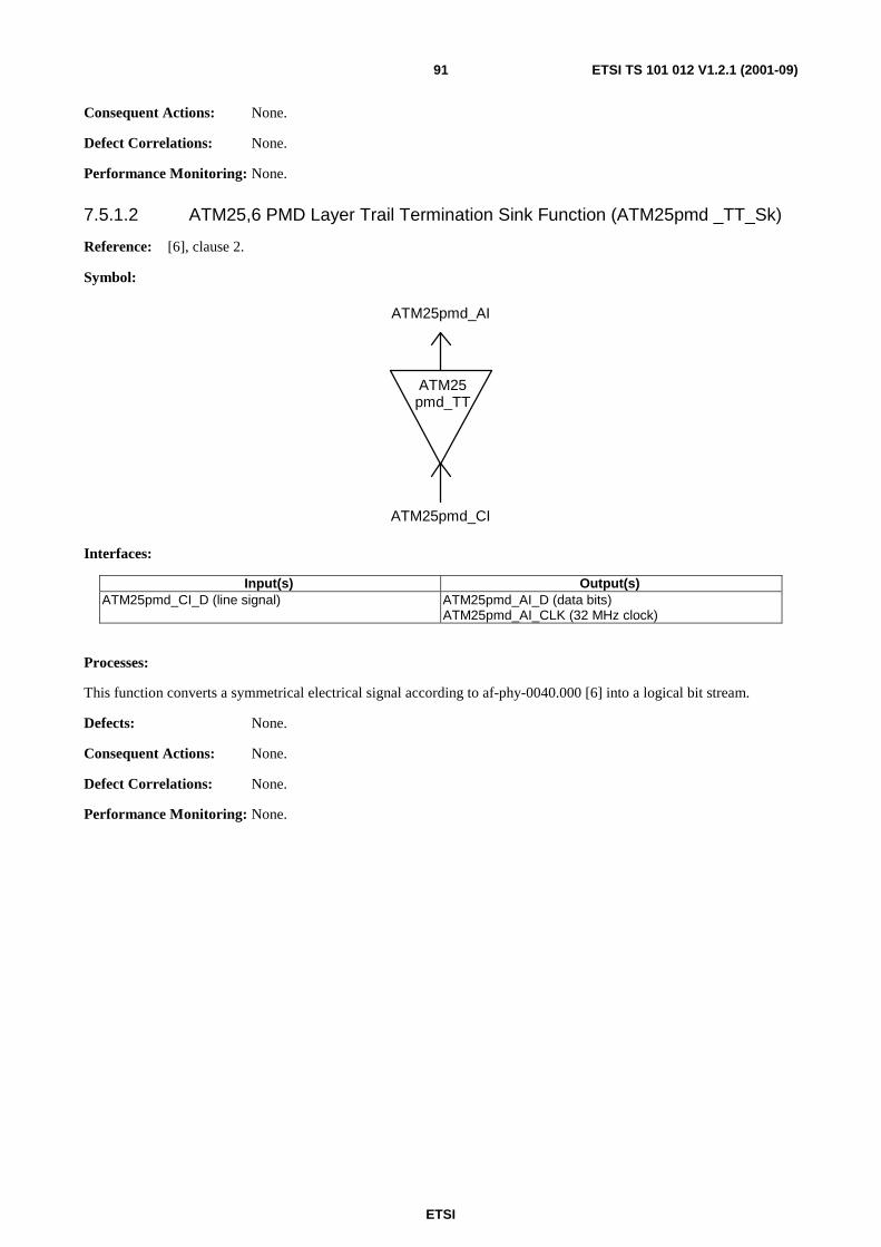
ETSI
ETSI TS 101 012 V1.2.1 (2001-09)91
Consequent Actions: None.
Defect Correlations: None.
Performance Monitoring: None.
7.5.1.2 ATM25,6 PMD Layer Trail Termination Sink Function (ATM25pmd _TT_Sk)
Reference: [6], clause 2.
Symbol:
ATM25 pmd_TT
ATM25pmd_CI
ATM25pmd_AI
Interfaces:
Input(s) Output(s) ATM25pmd_CI_D (line signal) ATM25pmd_AI_D (data bits)
ATM25pmd_AI_CLK (32 MHz clock)
Processes:
This function converts a symmetrical electrical signal according to af-phy-0040.000 [6] into a logical bit stream.
Defects: None.
Consequent Actions: None.
Defect Correlations: None.
Performance Monitoring: None.
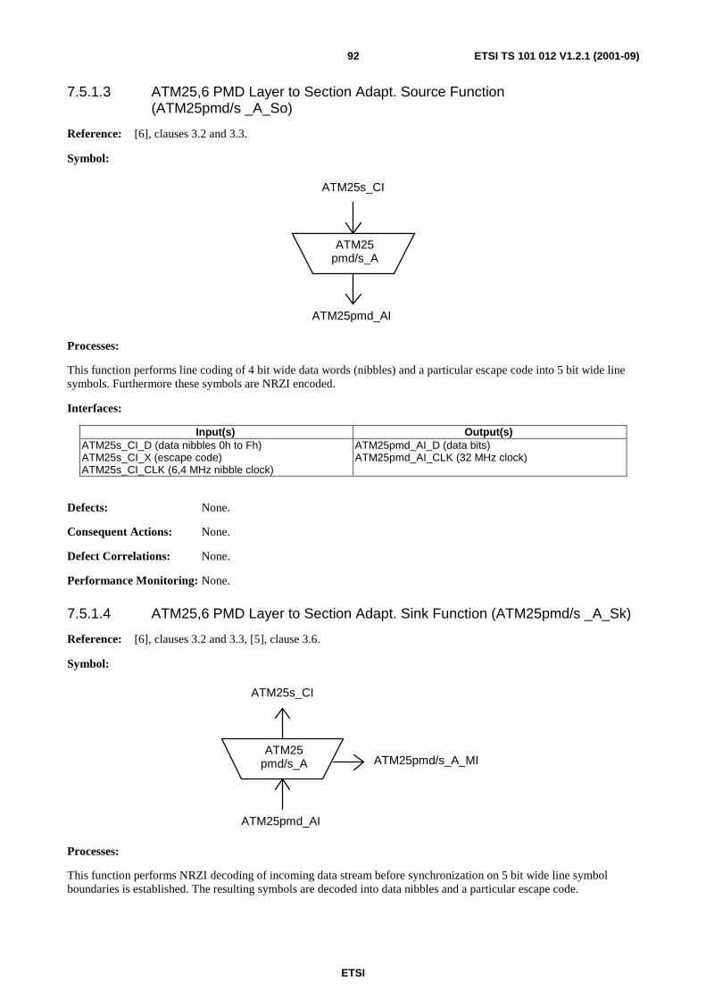
ETSI
ETSI TS 101 012 V1.2.1 (2001-09)92
7.5.1.3 ATM25,6 PMD Layer to Section Adapt. Source Function (ATM25pmd/s _A_So)
Reference: [6], clauses 3.2 and 3.3.
Symbol:
ATM25 pmd/s_A
ATM25s_CI
ATM25pmd_AI
Processes:
This function performs line coding of 4 bit wide data words (nibbles) and a particular escape code into 5 bit wide line symbols. Furthermore these symbols are NRZI encoded.
Interfaces:
Input(s) Output(s) ATM25s_CI_D (data nibbles 0h to Fh) ATM25s_CI_X (escape code) ATM25s_CI_CLK (6,4 MHz nibble clock)
ATM25pmd_AI_D (data bits) ATM25pmd_AI_CLK (32 MHz clock)
Defects: None.
Consequent Actions: None.
Defect Correlations: None.
Performance Monitoring: None.
7.5.1.4 ATM25,6 PMD Layer to Section Adapt. Sink Function (ATM25pmd/s _A_Sk)
Reference: [6], clauses 3.2 and 3.3, [5], clause 3.6.
Symbol:
ATM25 pmd/s_A
ATM25s_CI
ATM25pmd_AI
ATM25pmd/s_A_MI
Processes:
This function performs NRZI decoding of incoming data stream before synchronization on 5 bit wide line symbol boundaries is established. The resulting symbols are decoded into data nibbles and a particular escape code.

ETSI
ETSI TS 101 012 V1.2.1 (2001-09)93
Interfaces:
Input(s) Output(s) ATM25pmd_AI_D (data bits) ATM25pmd_AI_CLK (32 MHz clock)
ATM25s_CI_D (data nibbles 0h to Fh) ATM25s_CI_X (escape code) ATM25s_CI_CLK (6,4 MHz nibble clock) ATM25s_CI_SSF (server signal fail) ATM25pmd/s _A_Sk_MI_cLOQ ATM25pmd/s _A_Sk_MI_pIS
Defects:
dLOQ: If more than one invalid symbol is received in a logical block consisting of 216 contiguous symbols the LOQ defect shall be generated. It shall persist until a block with no more than 1 invalid symbol is detected.
Consequent Actions: aSSF ← dLOQ
Defect Correlations: cLOQ ← dLOQ
Performance Monitoring: pIS: Counter for invalid line symbols
7.5.2 ATM25,6 Section Layer Functions
ATM25 s_TT
ATM25 s_TT
ATM25 s/tp_A
ATM25s_CI
ATM25 s/tp_A
ATM25s_AI
ATM25,6 Section Layer Characteristic Information ATM25s_CI
4 bit wide data nibbles (0h to Fh) and a particular escape code.
ATM25,6 Section Layer Adaptation Information ATM25s_AI
Pairs of data nibbles and/or escape codes representing commands and data octets:
• escape code and 2 data nibble/escape code → command;
• data nibble pair -> data octet (scrambled information).

ETSI
ETSI TS 101 012 V1.2.1 (2001-09)94
7.5.2.1 ATM25,6 Section Layer Trail Termination Source Function (ATM25s _TT_So)
Reference: [6], clause 3.2.1.
Symbol:
ATM25 s_TT
ATM25s_CI
ATM25s_AI
Interfaces:
Input(s) Output(s) ATM25s_AI_D (commands and data octets) ATM25s_AI_CLK (3,2 MHz octet clock)
ATM25s_CI_D (data nibbles 0h to Fh) ATM25s_CI_X (escape code) ATM25s_CI_CLK (6,4 MHz nibble clock)
Processes:
This function splits the incoming data octets and commands into data nibbles and escape codes.
Defects: None.
Consequent Actions: None.
Defect Correlations: None.
Performance Monitoring: None.
7.5.2.2 ATM25,6 Section Layer Trail Termination Sink Function (ATM25s _TT_Sk)
Reference: [6], clause 3.2.1.
Symbol:
ATM25 s_TT
ATM25s_CI
ATM25s_AI
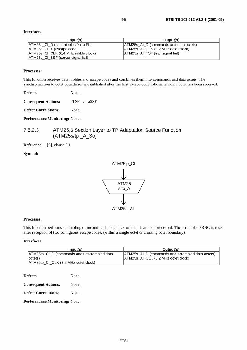
ETSI
ETSI TS 101 012 V1.2.1 (2001-09)95
Interfaces:
Input(s) Output(s) ATM25s_CI_D (data nibbles 0h to Fh) ATM25s_CI_X (escape code) ATM25s_CI_CLK (6,4 MHz nibble clock) ATM25s_CI_SSF (server signal fail)
ATM25s_AI_D (commands and data octets) ATM25s_AI_CLK (3,2 MHz octet clock) ATM25s_AI_TSF (trail signal fail)
Processes:
This function receives data nibbles and escape codes and combines them into commands and data octets. The synchronization to octet boundaries is established after the first escape code following a data octet has been received.
Defects: None.
Consequent Actions: aTSF ← aSSF
Defect Correlations: None.
Performance Monitoring: None.
7.5.2.3 ATM25,6 Section Layer to TP Adaptation Source Function (ATM25s/tp _A_So)
Reference: [6], clause 3.1.
Symbol:
ATM25 s/tp_A
ATM25tp_CI
ATM25s_AI
Processes:
This function performs scrambling of incoming data octets. Commands are not processed. The scrambler PRNG is reset after reception of two contiguous escape codes. (within a single octet or crossing octet boundary).
Interfaces:
Input(s) Output(s) ATM25tp_CI_D (commands and unscrambled data octets) ATM25tp_CI_CLK (3,2 MHz octet clock)
ATM25s_AI_D (commands and scrambled data octets) ATM25s_AI_CLK (3,2 MHz octet clock)
Defects: None.
Consequent Actions: None.
Defect Correlations: None.
Performance Monitoring: None.
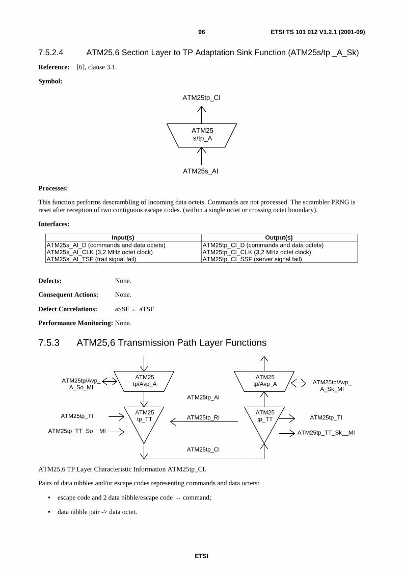
ETSI
ETSI TS 101 012 V1.2.1 (2001-09)96
7.5.2.4 ATM25,6 Section Layer to TP Adaptation Sink Function (ATM25s/tp _A_Sk)
Reference: [6], clause 3.1.
Symbol:
ATM25 s/tp_A
ATM25tp_CI
ATM25s_AI
Processes:
This function performs descrambling of incoming data octets. Commands are not processed. The scrambler PRNG is reset after reception of two contiguous escape codes. (within a single octet or crossing octet boundary).
Interfaces:
Input(s) Output(s) ATM25s_AI_D (commands and data octets) ATM25s_AI_CLK (3,2 MHz octet clock) ATM25s_AI_TSF (trail signal fail)
ATM25tp_CI_D (commands and data octets) ATM25tp_CI_CLK (3,2 MHz octet clock) ATM25tp_CI_SSF (server signal fail)
Defects: None.
Consequent Actions: None.
Defect Correlations: aSSF ← aTSF
Performance Monitoring: None.
7.5.3 ATM25,6 Transmission Path Layer Functions
ATM25 tp_TT
ATM25 tp_TT
ATM25 tp/Avp_A
ATM25tp_CI
ATM25 tp/Avp_A
ATM25tp_AI
ATM25tp_TI ATM25tp_TI
ATM25tp_TT_Sk__MI
ATM25tp_RI
ATM25tp_TT_So__MI
ATM25tp/Avp_ A_Sk_MI
ATM25tp/Avp_A_So_MI
ATM25,6 TP Layer Characteristic Information ATM25tp_CI.
Pairs of data nibbles and/or escape codes representing commands and data octets:
• escape code and 2 data nibble/escape code → command;
• data nibble pair -> data octet.

ETSI
ETSI TS 101 012 V1.2.1 (2001-09)97
The following commands are defined:
• Start of cell with/without scrambler reset in underlying adaptation functions;
• Sync event for transport of network timing reference signal;
• Remote defect indication (RDI) to inform the remote side about defects recognized at the local receiver.
The 53 data octets following a start of cell command contain the ATM cell data. This sequence may only interrupted by sync event commands. When no command and no ATM cell data have to be transmitted randomized idle data octets are inserted.
ATM25,6 TP Layer Adaptation Information ATM25tp_AI.
ATM cell data and start-of cell indication.
7.5.3.1 ATM25,6 TP Layer Trail Termination Source Function (ATM25tp _TT_So)
Reference: [6], clauses 3.2.1, 3.2.2 and 3.2.3, [5], clause 3.6.
Symbol:
ATM25 tp_TT
ATM25tp_CI
ATM25tp_AI
ATM25tp_RI ATM25tp_TI
ATM25tp_TT_So_MI
Interfaces:
Input(s) Output(s) ATM25tp_AI_D (ATM cell data) ATM25tp_AI_ACS (cell start indication) ATM25tp_RI_RDI (defect indication to remote side) ATM25tp_TI_SYNC (8 kHz reference clock) ATM25tp_TT_So_MI_SRES (scrambler reset)
ATM25tp_CI_D (commands and data octets) ATM25tp_CI_CLK (3,2 MHz octet clock)
Processes:
This function generates the transmission path message stream consisting of commands, ATM cell data and idle data. On request from management a command for scrambler reset in the corresponding adaptation functions to be sent at beginning of the next cell transfer is generated.
Defects: None.
Consequent Actions: None.
Defect Correlations: None.
Performance Monitoring: None.

ETSI
ETSI TS 101 012 V1.2.1 (2001-09)98
7.5.3.2 ATM25,6 TP Layer Trail Termination Sink Function (ATM25tp _TT_Sk)
Reference: [6], clauses 3.2.1, 3.2.2 and 3.2.3, [5], clause 3.6.
Symbol:
ATM25 tp_TT
ATM25tp_CI
ATM25tp_AI
ATM25tp_RI
ATM25tp_TI
ATM25tp_TT_Sk_MI
Interfaces:
Input(s) Output(s) ATM25tp_CI_D (commands and data octets) ATM25tp_CI_CLK (3,2 MHz octet clock) ATM25tp_CI_SSF (server signal fail)
ATM25tp_AI_D (ATM cell data) ATM25tp_AI_ACS (cell start indication) ATM25tp_AI_TSF (trail signal fail) ATM25tp_RI_RDI (defect indication to remote side) ATM25tp_TI_SYNC (8 kHz reference clock) ATM25tp_TT_So_MI_rRDI (remote defect)
Processes:
This function decodes the incoming transmission path messages and converts it into ATM cells. Furthermore the timing reference clock is regenerated and management information from remote end is passed to the local management.
Defects: None.
Consequent Actions:
aTSF ← aSSF
aRDI ← aSSF
Defect Correlations: None.
Performance Monitoring: None.

ETSI
ETSI TS 101 012 V1.2.1 (2001-09)99
7.5.3.3 ATM25,6 TP Layer to ATM V. P. Adapt. Source Function ATM25tp/Avp_A_So
Reference: [18], clause 4.2.1, [5], clause 3.4.
Symbol:
ATM25 tp/Avp_A
Avp_CI
ATM25tp_AI
ATM25tp/Avp_A_So_MI
Processes:
The ATM25tp/Avp_A_So function provides adaptation from the ATM Virtual Path layer to the ATM25 transmission path. This is performed by a grouping of Specific Processes and Common Processes according to the following list.
Specific Processes (characterized by the Virtual Path Identifier):
• VP activation/deactivation;
• ATM VPs asynchronous multiplexing.
Common Processes:
• congestion control (selective cell discard based on CLP);
• TP usage measurement;
• HEC processing.
Interfaces:
Input(s) Output(s) Avp_CI_D (ATM cell data - VP specific) Avp_CI_ACS (cell start indication) ATM25tp/Avp_A_So_MI_VPI-KActive (Activation VPI-K) ATM25tp/Avp_A_So_MI_TPusgActive (Activation TP usage measurement)
ATM25tp_AI_D (ATM cell data) ATM25tp_AI_ACS (cell start indication) ATM25tp/Avp_A_So_MI_pTx ATM25tp/Avp_A_So_MI_pCong
Defects: None.
Consequent Actions: None.
Defect Correlations: None.
Performance Monitoring: pTx: Counter for transmitted Cells.
pCong: Counter for Congestion events.

ETSI
ETSI TS 101 012 V1.2.1 (2001-09)100
7.5.3.4 ATM25,6 TP Layer to ATM V. P. Adapt. Sink Function (ATM25tp/Avp_A_Sk)
Reference: [18], clause 4.2.2, [5], clause 3.4.
Symbol:
ATM25 tp/Avp_A
Avp_CI
ATM25tp_AI
ATM25tp/Avp_A_Sk_MI
Processes:
The ATM25tp/Avp_A_Sk function provides adaptation from the ATM25 transmission path to the ATM Virtual Path layer. This is performed by a grouping of Specific Processes and Common Processes according to the following list:
Common Processes:
• TP usage measurement;
• Congestion Control;
• Header verification (only error detection);
• VPI verification.
Specific Processes (characterized by the Virtual Path Identifier):
• ATM VPs asynchronous demultiplexing;
• VP-AIS insertion.
Interfaces:
Input(s) Output(s) ATM25tp_AI_D (ATM cell data) ATM25tp_AI_ACS (cell start indication) ATM25tp_AI_TSF (trail signal fail) ATM25tp/Avp_A_Sk_MI_VPI-KActive (Activation VPI-K) ATM25tp/Avp_A_Sk_MI_VPIrange (Valid VPI range) ATM25tp/Avp_A_Sk_MI_TPusgActive (Activation TP usage measurement) ATM25tp/Avp_A_Sk_MI_DFLOC (Defect location field contents for VP-AIS cell)
Avp_CI_D (ATM cell data - VP specific) Avp_CI_ACS (cell start indication) Avp_CI_SSF (server signal fail) ATM25tp/Avp_A_Sk_MI_pRx ATM25tp/Avp_A_Sk_MI_pInvHead ATM25tp/Avp_A_Sk_MI_pHEC ATM25tp/Avp_A_Sk_MI_pCong
Defects: None.
Consequent Actions:
aSSF aTSF
aAIS aTSF
Defect Correlations: None.

ETSI
ETSI TS 101 012 V1.2.1 (2001-09)101
Performance Monitoring:
pRx: Counter for received Cells;
pCong: Counter for Congestion events;
pHEC: Counter for discarded cells due to invalid HEC checksum;
pInvHead: Counter for discarded cells due to invalid header patterns or invalid VIPs (out of range or not assigned).
7.6 Terminal Adapter Functions For further study.
7.7 Modelling of Equipment Management Functions For further study.

ETSI
ETSI TS 101 012 V1.2.1 (2001-09)102
Annex A (informative): Techniques of POTS/ISDN support This contribution is analysing the subject from two following viewpoints:
• power spectrum economy of ADSL and ISDN transport techniques;
• pros and cons of in-band ISDN transmission.
A.1 Spectral parameters of BA ISDN and ADSL signals At present, ADSL signals are transmitted above POTS or BA ISDN frequency bands. Case of ADSL over POTS will not be analysed in more details here, because the bandwidth blocked for POTS is not too wide.
Echo cancelled (EC) ADSL over ISDN systems shall comply with the transmit spectral masks shown in figure 46 and figure 47.
The ATU-C transmitter spectral response shall be as defined in figure 46 and in table 40.
120 1 104
3 093 11 040
Frequency in kHz 0
PSD in dBm/Hz
-90 dBm/Hz peak 12 dB/octave
-36 dB/octave
-36,5 peak
Measurements are into 100 ohms resistive termination,
4 545
-50 dBm power in any 1 MHz sliding window above 4 545 kHz
-90 dBm/Hz peak
50 80
NOTE: There is a discrepancy between the out-of-band power spectral density limits given in the present document and those given in a recently revised ETSI TS relating to ISDN-BA (TS 102 080 [32]). The out-of-band limits on ISDN-BA are more stringent than the ADSL system described in the present document. It is acknowledged that there is a need to make the documents consistent. This is an area under study in SP 1-12 of LL on TS 101 388 [33].
Figure 46: ATU-C transmitted PSD mask
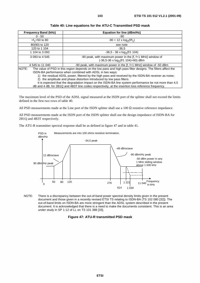
ETSI
ETSI TS 101 012 V1.2.1 (2001-09)103
Table 40: Line equations for the ATU-C Transmitted PSD mask
Frequency Band (kHz) Equation for line (dBm/Hz) 0 - 50 -90
>f1=50 to 80 -90 + 12 x log2(f/f1)
80(90) to 120 see note 120 to 1 104 -36,5
1 104 to 3 093 -36,5 - 36 x log2(f/1 104)
3 093 to 4 545 -90 peak, with maximum power in the [f, f+1 MHz] window of (-36,5-36 x log2(f/1 104)+60) dBm
4 545 to 11 040 -90 peak, with maximum power in the [f, f+1 MHz] window of -50 dBm NOTE: The value of PSD in this region depends on the low pass and high pass filter designs. The filters affect the
ISDN-BA performance when combined with ADSL in two ways: 1) the residual ADSL power, filtered by the high pass and received by the ISDN-BA receiver as noise; 2) the amplitude and phase distortion introduced by low pass filters. It is expected that the degradation impact on the ISDN-BA line system performance be not more than 4,5 dB and 4 dB, for 2B1Q and 4B3T line codes respectively, at the insertion loss reference frequency.
The maximum level of the PSD of the ADSL signal measured at the ISDN port of the splitter shall not exceed the limits defined in the first two rows of table 40.
All PSD measurements made at the Line port of the ISDN splitter shall use a 100 Ω resistive reference impedance.
All PSD measurements made at the ISDN port of the ISDN splitter shall use the design impedance of ISDN-BA for 2B1Q and 4B3T respectively.
The ATU-R transmitter spectral response shall be as defined in figure 47 and in table 41.
120 276
614 11 040
Frequency in kHz 0
PSD in dBm/Hz
-90 dBm/Hz peak 12 dB/octave
-48 dB/octave
-34,5 peak
Measurements are into 100 ohms resistive termination,
1 221
-50 dBm power in any 1 MHz sliding window above 1 630 kHz 90 dBm/Hz peak
50 80
1 630
NOTE: There is a discrepancy between the out-of-band power spectral density limits given in the present document and those given in a recently revised ETSI TS relating to ISDN-BA (TS 102 080 [32]). The out-of-band limits on ISDN-BA are more stringent than the ADSL system described in the present document. It is acknowledged that there is a need to make the documents consistent. This is an area under study in SP 1-12 of LL on TS 101 388 [33].
Figure 47: ATU-R transmitted PSD mask

ETSI
ETSI TS 101 012 V1.2.1 (2001-09)104
Table 41: ATU-R Transmitted PSD mask
Frequency band (kHz) Equation for line (dBm/Hz) 0 - 50 -90
>f1=50 to 80 -90 + 12 x log2(f/f1)
80 to 120 see note 120 to 276 -34,5 276 to 614 -34,5 - 48 x log2(f/276)
614 to 1 221 -90 1 221 to 1 630 -90 peak, with maximum power in the [f, f + 1 MHz] window of
(-90 - 48 x log2(f/1 221) + 60) dBm
1 630 to 11 040 -90 peak, with maximum power in the [f, f + 1 MHz] window of -50dBm NOTE: The value of PSD in this region depends on the low pass and high pass filter designs. The filters affect the
ISDN-BA performance when combined with ADSL in two ways: 1) the residual ADSL power, filtered by the high pass and received by the ISDN-BA receiver as noise; 2) the amplitude and phase distortion introduced by low pass filters. It is expected that the degradation impact on the ISDN-BA line system performance be not more than 4,5
dB and 4 dB, for 2B1Q and 4B3T line codes respectively, at the insertion loss reference frequency.
The maximum level of the PSD of the ADSL signal measured at the ISDN port of the splitter shall not exceed the limits defined in the first two rows of table 41.
All PSD measurements made at the Line port of the ISDN splitter shall use a 100 Ω resistive reference impedance.
All PSD measurements made at the ISDN port of the ISDN splitter shall use the design impedance of ISDN-BA for 2B1Q and 4B3T.
Frequency division duplexed (FDD) ADSL over ISDN systems shall comply with the transmit spectral masks shown in figure 48.
254 1 104
3 093 11 040
Frequency in kHz 0
PSD in dBm/Hz
-90 dBm/Hz peak 24 dB/octave
-36 dB/octave
-36,5 peak
Measurements are into 100 ohms resistive termination,
4 545
-50 dBm power in any 1 MHz sliding window above 4 545 kHz
-90 dBm/Hz peak
93.1 209
48 dB/octave
NOTE: There is a discrepancy between the out-of-band power spectral density limits given in the present document and those given in a recently revised ETSI TS relating to ISDN-BA (TS 102 080 [32]). The out-of-band limits on ISDN-BA are more stringent than the ADSL system described in the present document. It is acknowledged that there is a need to make the documents consistent. This is an area under study in SP 1-12 of LL on TS 101 388 [33].
Figure 48: ATU-C transmitted PSD mask

ETSI
ETSI TS 101 012 V1.2.1 (2001-09)105
Table 42: Line equations for the ATU-C Transmitted PSD mask
Frequency Band (kHz) Equation for line (dBm/Hz) 0 - 93.1 -90
93.1 to 209 -90 + 24xlog2(f/93.1)
209 to 254 -62 + 48xlog2(f/209)
254 to 1 104 -36,5 1 104 to 3 093 -36,5 - 36xlog2(f/1 104)
3 093 to 4 545 -90 peak, with maximum power in the [f, f+1 MHz] window of (-36,5-36 x log2(f/1 104)+60) dBm
4 545 to 11 040 -90 peak, with maximum power in the [f, f+1 MHz] window of -50 dBm
The maximum level of the PSD of the ADSL signal measured at the ISDN port of the splitter shall not exceed the limits defined in the first two rows of table 42.
All PSD measurements made at the Line port of the ISDN splitter shall use a 100 Ω resistive reference impedance.
All PSD measurements made at the ISDN port of the ISDN splitter shall use the design impedance of ISDN-BA for 2B1Q and 4B3T respectively.
A.2 Two mode ADSL system in access network architecture
Considering existing standardization of voice coding and applying in-band philosophy described above, two architectures of Access Network, depicted on figure 49 and figure 50 can be designed.
The first solution is depicted on figure 49, where POTS or ISDN signals exit DSLAM via V5.x interface. Further distinguishing between PSTN and VoIP voice routes is done in PSTN network.
DSLAM
ATU-C
PSTN
ATMMUX
MUXV5.x
ATU-C
POTS /BA ISDN
DATA
ATU-R
DATA
ATU-R
VAME
IP
VAME Voice on ATM Multiplication Equipment
POTS /BA ISDN
FeederNetwork
ATM
Figure 49: ADSL system with separated ATM data and PSTN streams on network side
The second solution is depicted on figure 50, where voice and ISDN signals are converted into ATM format in VAME block [22] in DSLAM. ATM cells coming from VAME and from ATU-Cs are multiplexed in ATM Mux. Forwarding of ATM cells into PSTN, ATM or IP networks is performed inside the ATM network.

ETSI
ETSI TS 101 012 V1.2.1 (2001-09)106
PSTNDATA
ATU-R
DATA
ATU-RIP
POTS /BA ISDN
FeederNetwork
DSLAM
ATU-C
ATMMUX
VAME
ATU-C
ATM
POTS /BA ISDN
Figure 50: ADSL system with integrated ATM data and PSTN streams on network side
Brief comparison of both Access Network architectures is done in table 45.
Table 43: Comparison of ADSL architecture with separated and integrated PSTN channels
ADSL architecture
Advantages Disadvantages
Separated PSTN stream
less complex DSLAM than with VAME block suitable for cases if DSLAM is collocated with LE
in long distant transport extra channels are required for transport of ATM and STM streams
Integrated PSTN stream
integrated transport channel for data and other signals, suitable for long distance transport
more complex DSLAM than with MUX V5.x superfluous complex separation of PSTN signal in case of collocation of DSLAM and LE
Both system architectures have their optimum application areas, both of which also reflect existing network situation. Therefore, both of them seem to find application in present networks with PSTN domination; in future, when HOSTs serve greater areas, the VAME version may reach higher penetration.

ETSI
ETSI TS 101 012 V1.2.1 (2001-09)107
Annex B (informative): Bibliography
- ITU-T Recommendation I.326: " Functional architecture of transport network based on ATM".
- ITU-T Recommendation G.992.2: "Splitterless asymmetric digital subscriber line (ADSL) Transceivers".
- ITU-T Recommendation G.961: "Digital transmission system on metallic local lines for ISDN basic rate access".

ETSI
ETSI TS 101 012 V1.2.1 (2001-09)108
History
Document history
V1.1.1 September 2000 Publication
V1.2.1 September 2001 Publication