ts 102 772 - v1.1.1 - digital video broadcasting (dvb ... · ch-1218 grand saconnex (geneva)...
TRANSCRIPT

ETSI TS 102 772 V1.1.1 (2010-09)
Technical Specification
Digital Video Broadcasting (DVB);Specification of Multi-Protocol Encapsulation - inter-burst
Forward Error Correction (MPE-iFEC)

ETSI
ETSI TS 102 772 V1.1.1 (2010-09)2
Reference DTS/JTC-DVB-244
Keywords broadcasting, data, digital, DVB, IP, mobile, TV,
video
ETSI
650 Route des Lucioles F-06921 Sophia Antipolis Cedex - FRANCE
Tel.: +33 4 92 94 42 00 Fax: +33 4 93 65 47 16
Siret N° 348 623 562 00017 - NAF 742 C
Association à but non lucratif enregistrée à la Sous-Préfecture de Grasse (06) N° 7803/88
Important notice
Individual copies of the present document can be downloaded from: http://www.etsi.org
The present document may be made available in more than one electronic version or in print. In any case of existing or perceived difference in contents between such versions, the reference version is the Portable Document Format (PDF).
In case of dispute, the reference shall be the printing on ETSI printers of the PDF version kept on a specific network drive within ETSI Secretariat.
Users of the present document should be aware that the document may be subject to revision or change of status. Information on the current status of this and other ETSI documents is available at
http://portal.etsi.org/tb/status/status.asp
If you find errors in the present document, please send your comment to one of the following services: http://portal.etsi.org/chaircor/ETSI_support.asp
Copyright Notification
No part may be reproduced except as authorized by written permission. The copyright and the foregoing restriction extend to reproduction in all media.
© European Telecommunications Standards Institute 2010.
© European Broadcasting Union 2010. All rights reserved.
DECTTM, PLUGTESTSTM, UMTSTM, TIPHONTM, the TIPHON logo and the ETSI logo are Trade Marks of ETSI registered
for the benefit of its Members. 3GPPTM is a Trade Mark of ETSI registered for the benefit of its Members and of the 3GPP Organizational Partners.
LTE™ is a Trade Mark of ETSI currently being registered for the benefit of its Members and of the 3GPP Organizational Partners.
GSM® and the GSM logo are Trade Marks registered and owned by the GSM Association.

ETSI
ETSI TS 102 772 V1.1.1 (2010-09)3
Contents
Intellectual Property Rights ................................................................................................................................ 5
Foreword ............................................................................................................................................................. 5
Introduction ........................................................................................................................................................ 5
1 Scope ........................................................................................................................................................ 8
2 References ................................................................................................................................................ 8
2.1 Normative references ......................................................................................................................................... 8
2.2 Informative references ........................................................................................................................................ 9
3 Definitions, symbols and abbreviations ................................................................................................... 9
3.1 Definitions .......................................................................................................................................................... 9
3.2 Symbols ............................................................................................................................................................ 11
3.3 Abbreviations ................................................................................................................................................... 12
4 Sender operation ..................................................................................................................................... 12
4.1 Introduction ...................................................................................................................................................... 12
4.2 Parameters ........................................................................................................................................................ 13
4.3 Initialization ..................................................................................................................................................... 14
4.4 Reception of New Datagram Burst ................................................................................................................... 14
4.5 Generation of IFEC-Burst ................................................................................................................................ 15
4.6 Time-Slice Burst Generation and Sending ....................................................................................................... 16
4.7 Datagram Burst to ADT Mapping .................................................................................................................... 16
4.8 Generation of iFDT .......................................................................................................................................... 16
5 Carriage of MPE-IFEC sections (normative) ......................................................................................... 17
5.1 Generalities....................................................................................................................................................... 17
5.2 Syntax and semantics ....................................................................................................................................... 17
5.3 Real time parameters ........................................................................................................................................ 18
6 Time Slice and FEC identifier descriptor (normative) ........................................................................... 19
6.1 Introduction (informative) ................................................................................................................................ 19
6.2 Descriptor (normative) ..................................................................................................................................... 19
6.3 Sliding Encoding with RS code (normative) .................................................................................................... 23
6.3.1 General ........................................................................................................................................................ 23
6.3.2 Parameter Definitions ................................................................................................................................. 23
6.3.3 Mapping Functions ..................................................................................................................................... 24
6.3.4 Generation of iFDT ..................................................................................................................................... 24
6.3.5 Memory considerations ............................................................................................................................... 24
6.4 Generalized Encoding with Raptor code (informative) .................................................................................... 24
6.4.1 General ........................................................................................................................................................ 24
6.4.2 Parameter Definitions ................................................................................................................................. 24
6.4.3 Mapping Functions ..................................................................................................................................... 25
6.4.4 Generation of iFDT ..................................................................................................................................... 25
6.4.5 Example Parameters ................................................................................................................................... 25
Annex A (informative): Receiver operation ......................................................................................... 27
A.1 Introduction ............................................................................................................................................ 27
A.2 General Process ...................................................................................................................................... 27
A.3 Parameters .............................................................................................................................................. 28
A.4 Burst number detection .......................................................................................................................... 28
A.5 Section Reception ................................................................................................................................... 30
A.6 Padding in ADST mapping .................................................................................................................... 30
A.7 Decoding ................................................................................................................................................ 31

ETSI
ETSI TS 102 772 V1.1.1 (2010-09)4
A.7.1 Input ................................................................................................................................................................. 31
A.7.2 RS decoding ..................................................................................................................................................... 31
A.7.3 Raptor decoding ............................................................................................................................................... 32
A.7.4 Output ............................................................................................................................................................... 32
History .............................................................................................................................................................. 33

ETSI
ETSI TS 102 772 V1.1.1 (2010-09)5
Intellectual Property Rights IPRs essential or potentially essential to the present document may have been declared to ETSI. The information pertaining to these essential IPRs, if any, is publicly available for ETSI members and non-members, and can be found in ETSI SR 000 314: "Intellectual Property Rights (IPRs); Essential, or potentially Essential, IPRs notified to ETSI in respect of ETSI standards", which is available from the ETSI Secretariat. Latest updates are available on the ETSI Web server (http://webapp.etsi.org/IPR/home.asp).
Pursuant to the ETSI IPR Policy, no investigation, including IPR searches, has been carried out by ETSI. No guarantee can be given as to the existence of other IPRs not referenced in ETSI SR 000 314 (or the updates on the ETSI Web server) which are, or may be, or may become, essential to the present document.
Foreword This Technical Specification (TS) has been produced by Joint Technical Committee (JTC) Broadcast of the European Broadcasting Union (EBU), Comité Européen de Normalisation ELECtrotechnique (CENELEC) and the European Telecommunications Standards Institute (ETSI).
NOTE: The EBU/ETSI JTC Broadcast was established in 1990 to co-ordinate the drafting of standards in the specific field of broadcasting and related fields. Since 1995 the JTC Broadcast became a tripartite body by including in the Memorandum of Understanding also CENELEC, which is responsible for the standardization of radio and television receivers. The EBU is a professional association of broadcasting organizations whose work includes the co-ordination of its members' activities in the technical, legal, programme-making and programme-exchange domains. The EBU has active members in about 60 countries in the European broadcasting area; its headquarters is in Geneva.
European Broadcasting Union CH-1218 GRAND SACONNEX (Geneva) Switzerland Tel: +41 22 717 21 11 Fax: +41 22 717 24 81
The Digital Video Broadcasting Project (DVB) is an industry-led consortium of broadcasters, manufacturers, network operators, software developers, regulatory bodies, content owners and others committed to designing global standards for the delivery of digital television and data services. DVB fosters market driven solutions that meet the needs and economic circumstances of broadcast industry stakeholders and consumers. DVB standards cover all aspects of digital television from transmission through interfacing, conditional access and interactivity for digital video, audio and data. The consortium came together in 1993 to provide global standardisation, interoperability and future proof specifications.
Introduction MPE-IFEC is introduced to support reception in situations of long duration erasure on the MPE section level spanning several consecutive time slice bursts. Such erasure situations may for example occur on LMS channels without any terrestrial repeaters in the vicinity: obstacles may hinder direct satellite reception and induce losses of several successive bursts. For example, with an MPE-IFEC protection where about 30 % of TS data are allocated to parity overhead computed over 10 successive bursts, it is possible to compensate up to 3 successive complete burst losses whereas recovery of a complete burst loss with DVB-H MPE-FEC protection would not be possible. Such erasure situation may also occur in terrestrial networks so that MPE-IFEC may be useful in other channels than LMS.
ETSI
ETSI TS 102 772 V1.1.1 (2010-09)6
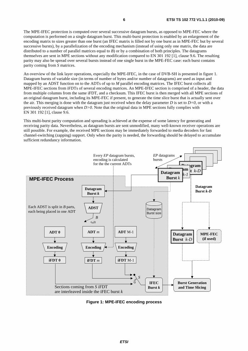
The MPE-IFEC protection is computed over several successive datagram bursts, as opposed to MPE-FEC where the computation is performed on a single datagram burst. This multi-burst protection is enabled by an enlargement of the encoding matrix to sizes greater than one burst (an IFEC matrix is filled not by one burst as in MPE-FEC but by several successive bursts), by a parallelization of the encoding mechanism (instead of using only one matrix, the data are distributed to a number of parallel matrices equal to B) or by a combination of both principles. The datagrams themselves are sent in MPE sections without any modification compared to EN 301 192 [1], clause 9.6. The resulting parity may also be spread over several bursts instead of one single burst in the MPE-FEC case: each burst contains parity coming from S matrices.
An overview of the link layer operations, especially the MPE-IFEC, in the case of DVB-SH is presented in figure 1. Datagram bursts of variable size (in terms of number of bytes and/or number of datagrams) are used as input and mapped by an ADST function on to the ADTs of up to M parallel encoding matrices. The IFEC burst collects all MPE-IFEC sections from iFDTs of several encoding matrices. An MPE-IFEC section is comprised of a header, the data from multiple columns from the same iFDT, and a checksum. This IFEC burst is then merged with all MPE sections of an original datagram burst, including its MPE-FEC if present, to generate the time slice burst that is actually sent over the air. This merging is done with the datagram just received when the delay parameter D is set to D=0, or with a previously received datagram when D>0. Note that the original data in MPE sections fully complies with EN 301 192 [1], clause 9.6.
This multi-burst parity computation and spreading is achieved at the expense of some latency for generating and receiving parity data. Nevertheless, as datagram bursts are sent unmodified, many well-known receiver operations are still possible. For example, the received MPE sections may be immediately forwarded to media decoders for fast channel-switching (zapping) support. Only when the parity is needed, the forwarding should be delayed to accumulate sufficient redundancy information.
Datagram Burst k-DDatagram
Burst k-1Datagram Burst k
Datagram Burst k
ADT m ADT M-1ADT 0
IFEC Burst k
Burst Generation and Time Slicing
MPE-FEC (if used)
Datagram Burst k-D
Encoding
iFDT m iFDT M-1
Sections coming from S iFDTare interleaved inside the iFEC burst k
iFDT 0
Each ADST is split in B parts,each being placed in one ADT
ADSTADST
MPE-IFEC Process
EncodingEncoding
DatagramBurst size
Every EP datagram bursts,encoding is calculated for the the current ADTs
S
EP datagramsbursts
Datagram Burst k-D
B
Figure 1: MPE-IFEC encoding process

ETSI
ETSI TS 102 772 V1.1.1 (2010-09)7
The MPE-IFEC is introduced in such a way that MPE-IFEC ignorant (but MPE and MPE-FEC capable) DVB receivers will be able to extract the MPE stream in a fully backwards-compatible way. This backwards compatibility holds both when the MPE-IFEC is used with and without Time Slicing. The use of MPE-IFEC is not mandatory and is defined separately for each elementary stream in the transport stream. For each elementary stream it is possible to choose whether or not MPE-IFEC is used, and if it is used, to choose the trade-off between IFEC overhead, extra delay and performance. Time critical services, without MPE-IFEC and therefore minimal delay, could therefore be transmitted together with less time critical services using MPE-IFEC, on the same transport stream but on different elementary streams.
ETSI
ETSI TS 102 772 V1.1.1 (2010-09)8
1 Scope The present document specifies a protection scheme for the MPE sections specifically adapted for broadcasting environments supporting long duration fadings such as DVB-SH.
• Clause 3 introduces the (normative) definitions, symbols and abbreviations.
• Clause 4 introduces the (normative) sender operation. The present document specifies a generic framework that exhibits enough flexibility for a variety of applications, some of which are mandated for a usage in DVB-SH in the "framework mapping" in clause 6.
• Clause 5 describes the (normative) carriage of MPE-IFEC sections.
• Clause 6 provides (normative) syntax of Time Slice and FEC identifier descriptor. Two mapping of the generic framework are given:
- One based on MPE-FEC Reed Solomon code (EN 301 192 [1], clause 9.5.1) and called "sliding RS encoding" is normative.
- Another based on Raptor code (TS 102 472 [2]) and called "generalized encoding with Raptor code" is informative.
• Annex A introduces (informative) prototype IFEC decoding.
NOTE: The present document is intended to be ultimately added as an annex to EN 301 192 [1] but can be used independently as it is natively self-contained.
2 References References are either specific (identified by date of publication and/or edition number or version number) or non-specific. For specific references, only the cited version applies. For non-specific references, the latest version of the reference document (including any amendments) applies.
Referenced documents which are not found to be publicly available in the expected location might be found at http://docbox.etsi.org/Reference.
NOTE: While any hyperlinks included in this clause were valid at the time of publication ETSI cannot guarantee their long term validity.
2.1 Normative references The following referenced documents are necessary for the application of the present document.
[1] ETSI EN 301 192 (V1.4.1): "Digital Video Broadcasting (DVB); DVB Specification for Data Broadcasting".
[2] ETSI TS 102 472 (V1.2.1): "Digital Video Broadcasting (DVB); IP Datacast over DVB-H: Content Delivery Protocols".
[3] ETSI TS 102 584 (V1.1.1): "Digital Video Broadcasting (DVB); DVB-SH Implementation Guidelines".
[4] ISO/IEC 13818-6: "Information technology - Generic coding of moving pictures and associated audio information - Part 6: Extensions for DSM-CC".
[5] ISO/IEC 13818-1: "Information technology - Generic coding of moving pictures and associated audio information: Systems".

ETSI
ETSI TS 102 772 V1.1.1 (2010-09)9
2.2 Informative references The following referenced documents are not necessary for the application of the present document but they assist the user with regard to a particular subject area.
Not applicable.
3 Definitions, symbols and abbreviations
3.1 Definitions For the purposes of the present document, the following terms and definitions apply:
Application Data Sub Table (ADST): function used to map IP datagrams in Application Data Tables (ADTs)
NOTE: The Application Data Sub Table (ADST) is a function that allows mapping of a datagram burst to an ADT: ADST(j) refers to the jth column of the result of the mapping of the datagram burst on an intermediate matrix of C columns and T rows whereby j=0,1,…, C-1. Mapping of a datagram burst with Layer 3 datagrams on such a C*T matrix is shown in figure 2: the leftmost columns of the matrix host all datagrams of a datagram burst. The remaining columns are filled with possible padding. The first datagram in the datagram burst starts with its first byte in the upper left corner of the matrix and goes downwards to the first column. The length of the datagrams MAY vary arbitrarily from datagram to datagram. Immediately after the end of one datagram the following datagram starts. If a datagram does not end precisely at the end of a column, it continues at the top of the following column. When all datagrams have entered the matrix, any unfilled byte positions are padded with zero bytes, making all columns completely filled. After the mapping, each position in the matrix hosts an information byte or padding byte. Maximum size of each datagram burst, max_datagram_burst_size, is restricted to C*T.
Columns 0 to C-1
Row
s0 to T
-1
1stdatagram
1stdatagram
(cont.)2
nddatagram
2nd
datagram (cont.)
3rd
datagram
last datagram (cont.)
Padding bytesPadding bytes (cont.)
Padding bytes (cont.)
… …
Figure 2: Datagram burst to ADST mapping
Application Data Table (ADT): table carrying the source symbols of an encoding matrix
NOTE: the ADT is generated by the ADST mapping function. Each Application Data Table (ADT) is arranged as a matrix of K=C*EP columns and T rows. Each column in each ADT is uniquely identified by its encoding matrix number m and its column number n=0,…, K-1 by ADT(m,n).
B: number of Application Data Table over which an ADST is distributed before the encoding process
D: delay for sending the MPE-IFEC sections after encoding process

ETSI
ETSI TS 102 772 V1.1.1 (2010-09)10
datagram burst: collection of one or several contiguous ISO layer 3 (Network layer) datagrams (e.g. IP datagrams)
NOTE 1: Datagram bursts are numbered with continuous sequence numbers k=0, 1, … The bytes constituting one datagram burst are made of the succession of the bytes constituting the ISO layer 3 datagram sequence, starting with the first byte of the header of the first datagram of the sequence and ending with the last byte of the payload of the last datagram of the sequence. Each byte in the datagram burst is assigned a position address that indicates the number of bytes separating the start of the burst from this byte. Each datagram within each datagram burst is assigned an address pointing to the first byte of the datagram. Therefore, each datagram is uniquely identified by its datagram burst number k and its address. Each datagram burst k is assigned a datagram burst size referred to by datagram_burst_size(k) which is equal to the address of the last byte of the last datagram in the burst plus one byte. Datagram burst size is limited to 218-1 = 262 143 bytes due to signalling range restrictions of the address field in the real-time parameters in MPE header. However, the maximum size of a datagram burst MAY be restricted by other constraints. It is assumed that each datagram burst does not exceed a certain maximum datagram burst size max_datagram_burst_size, whereby an upper limit for max_datagram_burst_size is 218-1 due to the above-mentioned signalling reasons. Furthermore, the number of datagrams in each burst as well as the datagram burst size MAY vary for each datagram burst. The generation of datagram bursts from the sequence of ISO layer 3 (Network layer) datagrams is not further discussed, as it MAY depend on many different aspects.
NOTE 2: A datagram burst corresponds to a time-slice burst as defined in EN 301 192 [1].
Encoding Period (EP): duration between two successive encoding events
NOTE 1: The duration is expressed in units of time-slice bursts. The Encoding Period, or EP, determines the frequency with which FEC is computed: an EP of 1 means that the encoding process occurs at every datagram burst whereas an EP greater than 1 means that the encoding process occurs every EP bursts. For EP>1, the encoding matrix capacity (Application Data Table) is EP times greater than with EP=1 so that it takes EP times longer to fill it with data. EP is expressed in datagram burst units. EP increases the encoding matrix size: since each ADT has K=C*EP columns, when EP is increased, the encoding matrix size is therefore increased. This allows IFEC to use very large encoding matrices where appropriate.
NOTE 2: This parameter normalizes several other parameters:
� EP normalizes the encoding process depth B, which is the number of ADTs, expressed in units of EPs, over which the datagram bursts are interleaved.
� EP also normalizes the spreading process parameter S. The IFEC sections in one IFEC burst are interleaved from S iFDTs; here again S is expressed in EP units.
Encoding Matrix (EM): union of one source Application Data Table and its corresponding parity IFEC Data Table
NOTE: The IFEC encoding process hosts M encoding matrices. Encoding matrices are sequentially numbered by m= 0,…, M-1. The actual number M depends on several parameters and is specified in clause 6. Each encoding matrix m contains exactly one Application Data Table (ADT), referred to by ADT(m) and one IFEC Data Table (iFDT), referred to by iFDT(m).
ADT iFDT
0
T-1
K-10 0 N-1
Figure 3: Encoding matrix

ETSI
ETSI TS 102 772 V1.1.1 (2010-09)11
IFEC bursts: collection of IFEC sections sent in one time-slice burst
NOTE: The maximum size of an IFEC burst is R, where R is a number of IFEC sections. A new IFEC burst is generated with the reception of each datagram burst k. Each IFEC section of an IFEC burst is uniquely defined by its burst number k' = k[kmax] and its IFEC section index j=0,…,R-1. Each such IFEC section is
therefore referred to as IFEC(k', j). Note that an IFEC burst MAY contain less than R IFEC sections and that the section indices MAY be not consecutive.
IFEC Data Tables (iFDT): table carrying the parity symbols of an encoding matrix
NOTE: Each IFEC Data Table) is arranged as a matrix of N columns and T rows. Each column in each iFDT is uniquely identified by its encoding matrix number m and its column number n=0,…, N-1 by iFDT(m,n). The iFDT hosts the parity symbols generated for the corresponding ADT of the same encoding matrix.
Land Mobile Satellite (LMS): typical channel suitable for modelling DVB-SH reception
M: total number of encoding matrices used in parallel by the encoding process
MPE-IFEC section: DSMCC section carrying the parity data resulting from the MPE-IFEC encoding process
NOTE: An IFEC section is comprised of a header, the data (parity symbols) from multiple iFDT columns in sequence, and a checksum. Structure of an MPE-IFEC section is specified in clause 5 and generation of the IFEC section is covered in clause 4.5.
S: number of parity matrices over which the parity symbols are interleaved before sending
time-slice burst: structured content of MPE, MPE-FEC and MPE-IFEC sections actually sent over the air
NOTE 1: A time-slice burst corresponding to datagram burst k consists of a collection of:
� MPE sections generated from datagram burst k-D.
� MPE-FEC sections generated from datagram burst k-D (if MPE-FEC is also used).
� IFEC burst k containing MPE-IFEC sections generated when datagram burst k was received.
NOTE 2: The transmission order of MPE sections, MPE-FEC sections, and MPE-IFEC sections is specified in clause 4.6. Note that each of the sections requires settings of relevant real-time parameters, including time slicing. Time-slicing information can only be set after the definition of the transmission order.
NOTE 3: A time-slice burst does not correspond strictly to a time-slice burst as defined in [1] but to a "burst" instead. See TS 102 584 [3], clause 6 for more details.
3.2 Symbols For the purposes of the present document, the following symbols apply.
• All symbols and parameters are in italics.
EXAMPLE 1: datagram_burst_size(k)
EXAMPLE 2: parameter k
• All fields that are transmitted are denoted with police courier new.
EXAMPLE: burst_number

ETSI
ETSI TS 102 772 V1.1.1 (2010-09)12
• All functions are defined according to this template:
output_unit function_name(input_unit parameter1, input_unit parameter2,…)
EXAMPLE 1: prev_burst_size = datagram_burst_size((k-j[jmax-1]-1+kmax)[kmax])
EXAMPLE 2: datagram_burst_size(k) is result of function datagram_burst_size applied to parameter k
EXAMPLE 3: ifdt_index(k) is the function ifdt_index with parameter k as input
• A [B] means A modulo B.
3.3 Abbreviations For the purposes of the present document, the following abbreviations apply:
ADST Application Data Sub Table ADT Application Data Table CRC Cyclic Redundancy Check DSMCC Digital Storage Media Command and Control DVB-H Digital Video Broadcast Handheld DVB-SH Digital Video Broadcast Satellite Handheld EM Encoding Matrix EP Encoding Period FEC Forward Error Correction iFDT IFEC Data Tables IFEC synonym of MPE-IFEC IP Internet Protocol ISO International Organization for Standardization LMS Land Mobile Satellite MPE Multi-Protocol Encapsulation MPE-FEC Multi-Protocol Encapsulation Forward Error Correction MPE-IFEC MPE Inter-burst Forward Error Correction RS Reed Solomon TS Transport Stream
4 Sender operation
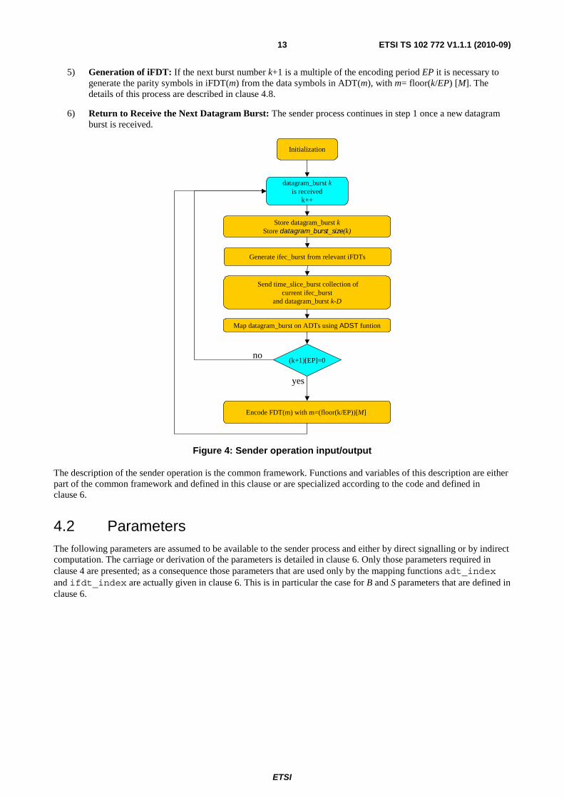
4.1 Introduction According to figure 1, the sender operation takes as its input the datagram bursts and generates at its output the time-slice bursts. The flow diagram of the sender operation is shown in figure 4. The initialization process before receiving the first datagram burst is described in clause 4.3. Then following procedure is applied for each newly received datagram burst.
1) Reception of new datagram burst: The burst number k is incremented by one. The actual datagram burst k is stored such that it can be delivered after delay D. Its datagram_burst_size(k) is stored.
2) Generation of IFEC burst: The corresponding IFEC burst is generated taking into account the current datagram burst k, the data in iFDTs, as well as the datagram_burst_size of previous datagram bursts. The details of this process are described in clause 4.5.
3) Time-slice burst generation and sending: The time-slice burst is generated from the MPE sections obtained from datagram burst k-D, possibly from the corresponding MPE-FEC sections included in this burst, and the IFEC sections of the corresponding IFEC burst. The details of this process are described in clause 4.6.
4) Datagram burst to ADTs mapping: The actual datagram burst k is mapped by the use of the ADST to the ADTs. The ADST mapping includes the necessary padding. The details of this process are described in clause 4.7.
ETSI
ETSI TS 102 772 V1.1.1 (2010-09)13
5) Generation of iFDT: If the next burst number k+1 is a multiple of the encoding period EP it is necessary to generate the parity symbols in iFDT(m) from the data symbols in ADT(m), with m= floor(k/EP) [M]. The details of this process are described in clause 4.8.
6) Return to Receive the Next Datagram Burst: The sender process continues in step 1 once a new datagram burst is received.
Initialization
Encode FDT(m) with m=(floor(k/EP))[M]
Map datagram_burst on ADTs using ADST funtion
yes
(k+1)[EP]=0no
datagram_burst kis received
k++
Store datagram_burst kStore datagram_burst_size(k)
Generate ifec_burst from relevant iFDTs
Send time_slice_burst collection ofcurrent ifec_burst
and datagram_burst k-D
Figure 4: Sender operation input/output
The description of the sender operation is the common framework. Functions and variables of this description are either part of the common framework and defined in this clause or are specialized according to the code and defined in clause 6.
4.2 Parameters The following parameters are assumed to be available to the sender process and either by direct signalling or by indirect computation. The carriage or derivation of the parameters is detailed in clause 6. Only those parameters required in clause 4 are presented; as a consequence those parameters that are used only by the mapping functions adt_index and ifdt_index are actually given in clause 6. This is in particular the case for B and S parameters that are defined in clause 6.

ETSI
ETSI TS 102 772 V1.1.1 (2010-09)14
Table 1: MPE-IFEC generic parameters list
Parameter Unit Category Description Signalling Scoping EP Datagram
burst Taxonomy IFEC Encoding Period Direct via
Time_slice_fec_identifier Time_slice_fec_ide
ntifier D Datagram
burst Taxonomy Datagram burst sending
delay Direct via
Time_slice_fec_identifier Time_slice_fec_ide
ntifier T rows Table sizing Number of ADST, ADT,
iFDT rows: T= MPE-FEC Frame rows /G
Indirect via Time_slice_fec_identifier
Time_slice_fec_identifier
C columns Table sizing Number of ADST columns Direct via Time_slice_fec_identifier
Time_slice_fec_identifier
R sections Table sizing Maximum number of MPE IFEC sections per Time-
Slice Burst
Direct via Time_slice_fec_identifier
Time_slice_fec_identifier
K columns Table sizing Number of ADT columns = EP*C
Indirect via Time_slice_fec_identifier
Time_slice_fec_identifier
N columns Table sizing Number of iFDT columns = EP*R*G
Indirect via Time_slice_fec_identifier
Time_slice_fec_identifier
G columns Table sizing Maximum number of iFDT columns per IFEC section
Direct Time_slice_fec_identifier
M ADT Protocol sizing
Number of concurrent encoding matrices M
Indirect (formula dependent on T_code and
given in the parameter definition of clause 6)
Time_slice_fec_identifier
kmax N/A Protocol sizing
Modulo operator for IFEC burst counter
Indirect (formula dependent on T_code and
given in the parameter definition of clause 6)
Time_slice_fec_identifier
jmax N/A Protocol sizing
Maximum backward pointing for datagram
burst size used in PREV_BURST_SIZE
parameter in clause 3.5
Indirect (formula dependent on T_code and
given in the parameter definition of clause 6)
Time_slice_fec_identifier
K datagramburst
Index continuous burst counter internal to sender
N/A Loop
k' IFEC burst field Burst number N/A IFEC section
4.3 Initialization Before the first datagram burst is received, the following actions are required:
• The internal burst number k is set to any suitable value, e.g. kmax-1.
• M concurrent encoding matrices are allocated, each with one ADT of size K times T and one iFDT with size N times T.
• Each ADT and iFDT is filled entirely with 0 bytes.
• The datagram burst size of virtual previous bursts k=0,…,kmax-1 is set to 0, i.e. for all k=0,…,kmax-1
datagram_burst_size(k)=0.
4.4 Reception of New Datagram Burst With the reception of a new datagram burst, the following steps are carried out:
• Assign datagram burst number k by incrementing counter k of one unit.
• Store the corresponding datagram burst size datagram_burst_size(k).
• Store the datagram burst k such that it can be delivered after delay D.

ETSI
ETSI TS 102 772 V1.1.1 (2010-09)15
4.5 Generation of IFEC-Burst An IFEC burst is generated taking into account the current burst number k, data in iFDTs, as well as the datagram burst size of previous datagram bursts. In total, at most R IFEC sections are generated for each IFEC burst. Each IFEC section in this burst gets assigned a unique IFEC burst number k'=k [kmax]. In addition, each IFEC section gets assigned
a unique section index j with j=0,1,…, R-1.
For each MPE-IFEC section IFEC(k',j) with IFEC burst number k' and section index j included in the IFEC burst, the following information is generated:
• burst_number = k'; this value is used to identify to which IFEC burst the current section belongs. This value MUST be lower or equal to 255.
• IFEC_burst_size: this value defines the total number of IFEC sections included in this IFEC burst and is coded over 8 bits as the number of IFEC sections present in the IFEC burst minus one. IFEC_burst_size value of '0' means only one IFEC section is present in the IFEC burst. IFEC_burst_size maximum value MUST be lower or equal to last_section_number and R-1.
• section_number = j; j varies between '0' (first section) and last_section_number. j MAY be larger than IFEC_burst_size. The iFDT index is obtained as m = ifdt_index(k', j); equivalently m is the encoding matrix number as defined in clause 3.
• last_section_number: the largest value that is encoded in the section_number field for the same table-id, version fields and burst_number. A value of 255 SHALL be used for last_section_number if this largest value is not known.
• section_length = g*T+13.
• prev_burst_size = datagram_burst_size((k-j[jmax-1]-1+kmax)[kmax]).
• The remaining real-time parameters are set according to clause 4.6.
• IFEC_data_bytes are obtained from iFDT(m) and correspond to the sequence of the iFDT columns iFDT(m, i), iFDT(m, i+1), …, iFDT(m, i+g-1) with i = ifdt_column(k', j) and g any integer between 1 and G. Each column iFDT(m) contributes databytes in order from row 1 to row T.
iFEC_burst_size
12 bytes g*T
burst_number = k’ < kmax
iFEC_burst_size ≤ R-1section_number = jLast_section_number ≤ 255section_length = g*T+ 13Prev_burst_size = datagram_burst_size(k-j[jmax-1]-1+ kmax)[kmax]
m = fdt_index(k’, j)i = fdt_column(k’, j)g any integer between 1 and G
columns FDT(m, i),…, FDT(m, i+ g-1)
4
iFEC_data_bytesiFEC_header CRCiFEC_data_bytesiFEC_header CRCiFEC_data_bytesiFEC_header CRCiFEC_data_bytesiFEC_header CRCiFEC_data_bytesiFEC_header CRCiFEC_data_bytesiFEC_header CRCiFEC_data_bytesiFEC_header CRCiFEC_data_bytesiFEC_header CRCiFEC_data_bytesiFEC_header CRC32iFEC_data_bytesiFEC_header CRC32
Figure 5: Generation of IFEC burst
The exact mapping of this header and payload information on IFEC sections is provided in clause 5.2. The functions ifdt_index(k', j) and ifdt_column(k', j) are specified in clause 6 and depend on T_code signalled in id_selector_bytes of time_slicing_fec_descriptor and some additional parameters in the id_selector_bytes and time_slicing_fec_descriptor.

ETSI
ETSI TS 102 772 V1.1.1 (2010-09)16
4.6 Time-Slice Burst Generation and Sending The time-slice burst is generated from the MPE sections obtained from datagram burst k-D, possibly from the corresponding MPE-FEC sections included in this burst k-D, and the IFEC sections of the corresponding IFEC burst generated when datagram burst k was received. The rules for generating this time-slice burst are listed below:
• A time-slice burst MUST contain all datagrams in the same order coming from datagram_burst(k-D):
- Datagram encapsulation is identical to the one specified in EN 301 192 [1], clause 9.6.
- MPE sections within one time-slice burst SHALL be sent with increasing address.
• A time-slice burst MAY contain MPE-FEC sections related to this datagram burst k-D, if present. The generation and encapsulation of such MPE-FEC sections SHALL follow the procedure described in EN 301 192 [1], clause 9.
• A time-slice burst MAY contain IFEC sections of the corresponding IFEC burst. The encapsulation of the IFEC burst into IFEC sections is described in clauses 4.5 and 5.2.
The following rules apply to MPE, MPE-FEC, and IFEC sections sending order within time-slice burst corresponding to the received datagram burst k:
• IFEC sections and MPE sections MAY be freely interleaved if their respective orders are respected.
• Since the only MPE-IFEC section conveys burst numbering information, at least one MPE-IFEC section SHOULD be positioned close to the beginning of the time-slice burst.
• Last IFEC section MAY be sent before last MPE section.
After having specified the sending order, for each of the MPE sections transmitted, the real-time parameters SHALL be set accordingly. For IFEC sections, the real-time parameters delta_t, MPE_boundary, and frame_boundary SHALL be set as specified in clause 5.3.
4.7 Datagram Burst to ADT Mapping The datagram burst k is mapped by ADST function to the ADT, including the necessary padding as specified in clause 3. Then, for j= all 0,…,C-1 the ADST columns ADST(j) are shifted into ADT(m), whereby:
• k'=k[kmax] and m = adt_index(k', j).
• Shifting means that column ADST(j) is inserted at the right of ADT(m) moving all other columns to the left:
- ADT(m,0) = ADT(m,1)
- ADT(m,1) = ADT(m,2)
- …
- ADT(m, K-2) = ADT(m,K-1)
- ADT(m, K-1) = ADST(j)
m=adt_index(k', j) is specified in clause 6. Note that the insertion of columns in ADTs via ADST function is independent of whether ADST(j) is a data or a padding column: they are treated identically.
4.8 Generation of iFDT If the next burst number k+1 is a multiple of the encoding period EP it is necessary to generate the N parity symbols in iFDT(m) from the K data symbols in ADT(m), with m= floor(k/EP) [M].
The details of iFDT generation are presented in clause 6 and depend on T_code signalled in id_selector_bytes of time_slicing_fec_descriptor.

ETSI
ETSI TS 102 772 V1.1.1 (2010-09)17
5 Carriage of MPE-IFEC sections (normative)
5.1 Generalities When time_slice_fec_identifier_descriptor specifies that MPE-IFEC is used on an elementary stream, the MPE-IFEC parity of each Time-Slice burst SHALL be delivered in MPE-IFEC sections described in table 2. MPE-IFEC sections are carried in the same elementary stream as the corresponding MPE data sections.
5.2 Syntax and semantics MPE-IFEC sections are compliant to the DSMCC_section Type "User private" in ISO/IEC 13818-6 [4]. The mapping of the section into MPEG-2 Transport Stream packets is defined in ISO/IEC 13818-1 [5]. The syntax and semantics of the MPE-IFEC section are defined in table 2.
Table 2: MPE-IFEC section
Syntax Number of bits Identifier MPE-IFEC_section () { table_id 8 uimsbf section_syntax_indicator 1 Bslbf Private_indicator 1 Bslbf Reserved 2 Bslbf section_length 12 uimsbf Burst_number 8 uimsbf IFEC_burst_size 8 uimsbf Reserved 2 Bslbf Version 5 Uimsbf Current_next_indicator 1 Bslbf section_number 8 uimsbf last_section_number 8 real_time_parameters() 32 uimsbf for( i=0; i<Nmax; i++ ) { IFEC_data_byte 8 uimsbf } CRC_32 32 rpchof }
The semantics for the MPE-IFEC section are:
table_id: Shall be set to value of 0x7A.
section_syntax_indicator: This field SHALL be set to 1 and be interpreted as defined by ISO/IEC 13818-6 [4], clause 9.2.2.1.
private_indicator: This field SHALL be set to 0 and be interpreted as defined by ISO/IEC 13818-6 [4], clause 9.2.2.1.
reserved: Shall be set to '11'.
section_length: Specifies the number of remaining bytes in the section immediately following this field up to the end of the section, including the CRC.
burst_number: This carries a burst continuity counter that SHALL vary between 0 and kmax-1, where kmax is the
largest multiple of EP below 256. See clause 4.5.
IFEC_burst_size: this 8-bit field gives total number of IFEC sections transmitted in the current time_slice_burst as defined in clause 4.5.
reserved: These two bits SHALL be set to '11'.

ETSI
ETSI TS 102 772 V1.1.1 (2010-09)18
version: This 5-bits field gives the version of the MPE-IFEC protocol signalled by this section. It MUST be set to '00000'.
current_next_indicator: Shall be set to a value of '1' and interpreted as defined by ISO/IEC 13818-1 [5], clause 2.4.4.11 ("current section is immediately applicable").
section_number: This 8-bit field gives the index of the section as defined in clause 4.5.
last_section_number: The largest value that is encoded in the section-number field for the same table-id, version fields and burst_number fields. See clause 4.5.
Real time parameters: See clause 5.3.
IFEC_data_byte: Contains the IFEC data delivered as specified in clause 4.5. Nmax is equal to section_length–9.
CRC_32: This field SHALL be set as defined by [4]. It is calculated over the entire MPE-IFEC_section.
5.3 Real time parameters Each MPE-IFEC section SHALL carry real time parameters described in table 3.
Table 3: Time Slicing and MPE-IFEC real time parameters
Syntax Number of bits Identifier real_time_parameters () { delta_t 12 uimsbf MPE_boundary 1 bslbf frame_boundary 1 bslbf prev_burst_size 18 uimsbf }
delta_t: Usage of this 12-bit field depends on whether Time Slicing is used on the elementary stream.
The following applies when Time Slicing is used:
• The field indicates the time (delta-t) to the next Time-slice burst within the elementary stream. The time information is in each MPE-IFEC sections within a burst and the value MAY differ section by section. The resolution of the delta-t is 10 ms. Value 0x00 is reserved to indicate that no more bursts will be transmitted within the elementary stream (e.g. end of service). In such a case, all MPE-IFEC sections within the burst SHALL have the same value in this field as the MPE section.
• Delta-t information is the time from the start of the transport packet carrying the first byte of the current IFEC section to the start of the transport packet carrying the first byte of next burst. Therefore the delta-t information MAY differ between IFEC sections within a burst.
• The time indicated by delta-t SHALL be beyond the end of the maximum burst duration of the actual elementary stream. This ensures a decoder can always reliably distinguish two sequential bursts within an elementary stream.
The following applies when Time Slicing is not used:
• The field supports a cyclic ADST index within the elementary stream. The value of the field increases by one for each subsequent ADST. After value '111111111111', the field restarts from '000000000000'.
• In case of large portions of lost data this parameter makes it possible to identify to which ADST the actual received section belongs.

ETSI
ETSI TS 102 772 V1.1.1 (2010-09)19
MPE_boundary: This 1-bit flag, when set to '1', indicates that there are not any more MPE sections after this IFEC section in the time slice burst.
frame_boundary: This 1-bit flag, when set to '1', indicates that the current section is the last IFEC section of the time slice burst.
prev_burst_size: The field carries a description of the previous datagram burst size as specified in clause 4.5.
6 Time Slice and FEC identifier descriptor (normative)
6.1 Introduction (informative) This descriptor identifies whether MPE-IFEC is used on an elementary stream, in addition to the signalling of MPE-FEC. So the current specification comes in addition to the one found in [1], clause 9.5 without contradicting it. In particular absolutely no change has been done on fields used by MPE-FEC.
The differences are:
1) the use of the id_selector_bytes (text in id_selector_byte table);
2) the time_slice_fec_id that can be set to 0x0 and 0x1 values (a new value MUST be inserted wherever a reference to time_slice_fec_id is made).
For clarity purpose, the text before the id_selector_bytes has been reproduced.
6.2 Descriptor (normative)
Table 4: Time Slice and FEC identifier descriptor
Syntax Number of bits Identifier time_slice_fec_identifier_descriptor () { descriptor_tag 8 uimsbf descriptor_length 8 uimsbf time_slicing 1 bslbf mpe_fec 2 uimsbf reserved_for_future_use 2 bslbf frame_size 3 uimsbf max_burst_duration 8 uimsbf max_average_rate 4 uimsbf time_slice_fec_id 4 uimsbf for( i=0; I<id_selector_length; i++ ) {
id_selector_byte 8 bslbf } }
descriptor_tag: Shall be set to value of 0x77.
descriptor_length: This 8-bit field specifies the number of bytes of the descriptor immediately following this field.
time_slicing: This 1-bit field indicates, whether the referenced elementary stream is Time Sliced. The value "1" indicates Time Slicing being used, and the value "0" indicates that Time Slicing is not used.
mpe_fec: This 2-bit field indicates whether the referenced elementary stream uses MPE-FEC, and which algorithm is used. Coding is according to table 5.

ETSI
ETSI TS 102 772 V1.1.1 (2010-09)20
Table 5: Syntax and semantics for mpe_fec
value MPE-FEC algorithm 00 MPE-FEC not used n/a 01 MPE-FEC used Reed-Solomon (255, 191, 64) 10 Reserved for future use 11 Reserved for future use
reserved_for_future_use: This 2-bit field SHALL be set, when not used, to '11'.
frame_size: This 3-bit field is used to give information that a decoder MAY use to adapt its buffering usage:
• In case Time Slicing is used (i.e. time_slicing is set to "1"), this field indicates the maximum number of bits on section payloads allowed within a Time-slice burst on the elementary stream, excluding MPE-IFEC sections. For MPE sections, bits are counted over ip_datagram_data_bytes or LLC_SNAP field (whichever is supported), excluding any possible stuffing_bytes. For MPE-FEC sections, bits are counted over rs_data_bytes.
• When MPE-FEC is used (i.e. mpe_fec is set to 0x1), this field indicates the exact number of rows on each MPE-FEC Frame on the elementary stream.
• If both Time Slicing and MPE-FEC are used on an elementary stream, both constraints (i.e. the maximum burst size and the number of rows) apply.
• When MPE-IFEC is used (time_slice_fec_id is set to 0x1) this field is computed as in the case both time slicing and MPE-FEC are used.
• Coding of the frame_size is according to table 6.
Table 6: Syntax and semantics for frame_size
Size Max Burst Size MPE-FEC Frame rows 0x00 512 kbits = 524 288 bits 256 0x01 1 024 kbits 512 0x02 1 536 kbits 768 0x03 2 048 kbits 1 024
0x04 to 0x07 Reserved for future use reserved for future use
max_burst_duration: This 8-bit field is used to indicate the maximum burst duration in the elementary stream when time slicing is used. A burst SHALL not start before T1 and SHALL end not later than at T2, where T1 is the time indicated by delta-t in the previous burst, and T2 is T1 + maximum burst duration. If the time_slice_fec_id is set to 0x0 or 0x1, the indicated value for maximum burst duration SHALL be from 20 ms to 5,12 s, the resolution is 20 ms, and the field is decoded according to the following formula:
Maximum burst duration = (max_burst_duration + 1) × 20 ms
If the time_slice_fec_id is set to any other value than 0x0 or 0x1, the coding of the max_burst_duration is currently not defined. When time_slicing is set to '0' (i.e. Time Slicing not used), this field is reserved for future use and SHALL be set to 0xFF when not used.
max_average_rate: This 4-bit field is used to define the maximum average bit rate in MPE section payload level over one time slicing cycle or MPE-FEC frame or ADST cycle and it is given by:
c
sb T
BC = ,

ETSI
ETSI TS 102 772 V1.1.1 (2010-09)21
where Bs is the size of the current Time Slicing burst or MPE-FEC Frame or ADST cycle in MPE section payload bits
and Tc is the time from the transport packet carrying the first byte of the first MPE section in the current burst/frame to
the transport packet carrying the first byte of the first MPE section in the next burst/frame within the same elementary stream. Note that, when MPE-FEC is used, the RS data is not included in Bs nor is the IFEC parity data when
MPE-IFEC is used. If time_slice_fec_id is set to 0x0 or 0x1, the coding of the max_average_rate is according to table 7. If time_slice_fec_id is set to any other value, coding of the max_average_rate is currently not defined.
Table 7: Syntax and semantics for max_average_rate
Code Bitrate 0000 16 kbps 0001 32 kbps 0010 64 kbps 0011 128 kbps 0100 256 kbps 0101 512 kbps 0110 1 024 kbps 0111 2 048 kbps
1000 to 1111 reserved for future use
time_slice_fec_id: This 4-bit field identifies the usage of following id_selector_byte(s). Note that this field affects on coding of frame_size, max_burst_duration and max_average_rate fields on the actual descriptor, and the address field of real-time parameters on the referred elementary stream. If this field is set to value 0x0 id_selector_byte(s) SHALL not be present. If this field is set to value 0x1 then the id bytes are the following. Other values are not defined.
id_selector_length: Gives the lengths of the id_selector_byte field counted in bytes as given by table 8.
Table 8: Syntax and semantics for id_selector_length
Time_slice_fec_id Id_selector_length in bytes 0x0 0 0x1 9
other Undefined
id_selector_byte: If time_slice_fec_id is set to 0x1 the bytes have the following definition:
Table 9: Semantics for time_slice_fec_id = 0x1
Syntax Number of bits Identifier Time_slice_fec_id_0x1() { T_code 2 Uimsbf G_code 3 uimsbf Reserved for future use 3 bslbf R 8 uimsbf C 13 uimsbf Reserved for future use 3 bslbf B 8 uimsbf S 8 uimsbf D 8 uimsbf EP 8 uimsbf Max_rate_averaged_over_B 8 uimsbf }
T_code: This 2-bit field indicates the type of IFEC code used. Currently only value 0 is used and corresponds to MPE-FEC Reed Solomon (255,191).
Clause 6.4 adds an informative paragraph introducing the use of Raptor codes as specified in [2], clause C.4 in the framework.

ETSI
ETSI TS 102 772 V1.1.1 (2010-09)22
Table 10: Syntax and semantics for T_code
Bit rate Description 00 Reed Solomon code ([1], clause 9.5.1) 01 Raptor Codes ([2], clause C.4)
01 to 11 Reserved for future use
G_code: This 3-bit field indicates value of the G parameter as G=2^G_code (number of symbols).
Table 11: Syntax and semantics for G_code parameter
Bit rate G 000 1 001 2 010 4 011 8 100 16 101 32 110 64 111 128
reserved_for_future_use: This 3-bit field SHALL be set, when not used, to "111".
R: This 8-bit field indicates the maximum number of MPE-IFEC sections transmitted in an IFEC burst.
C: This 13-bit field indicates the number of columns for the ADST.
reserved_for_future_use: This 3-bit field SHALL be set, when not used, to "111".
B: This 8-bit field indicates value of the encoding process depth parameter normalized by EP. B is the number of ADTs over which the datagram bursts are interleaved.
S: This 8-bit field indicates value of the spreading process parameter normalized by EP: the IFEC sections in one IFEC burst are interleaved from iFDT.
D: This 8-bit field indicates value of the delaying process parameter. D is the number of datagram bursts by which the current transmission lags the current datagram burst.
EP: This 8-bit field indicates value of the encoding period parameter.
Max_rate_averaged_over_B: This 8-bit field is used to define the maximum bit rate in MPE section payload averaged over B time slicing cycle or MPE-FEC frame or ADST cycle and it is given by:
[ ]
[ ] ( )( ) ( )
0n
n
1-B1EPEPn-ni
EPn-nii
B T
B
maxC
≥∀
+−+=
=
⎟⎟⎟⎟⎟⎟
⎠
⎞
⎜⎜⎜⎜⎜⎜
⎝
⎛
=∑
where
• Bi is the size of ith Time Slicing burst or MPE-FEC Frame or ADST cycle in MPE section payload bits;
• Tn is the time from the transport packet carrying the first byte of the first MPE section in burst/frame n-n[EP]
to the transport packet carrying the first byte of the first MPE section in burst/frame (n-n[EP]+(EP-1)+B) within the same elementary stream.
When MPE-FEC is used, the RS data is not included in Bi nor is the IFEC parity data when MPE-IFEC is used.

ETSI
ETSI TS 102 772 V1.1.1 (2010-09)23
If time_slice_fec_id is set to 0x1, the coding of the max_rate_averaged_over_B is equal to floor(max_rate_averaged_over_B/8) where max_rate_averaged_over_B is expressed in kbps. If time_slice_fec_id is set to any other value, coding of the max_rate_averaged_over_B is currently not defined.
NOTE: max_rate_averaged_over_B is always ≤ max_average_rate.
6.3 Sliding Encoding with RS code (normative)
6.3.1 General
This encoding scheme is an extension of the MPE-FEC. It uses the same encoding parity code as the MPE-FEC, benefiting from its existing hardware support.
6.3.2 Parameter Definitions
The following parameter restrictions apply:
• The T_code value SHALL be set to 00.
• The encoding period MUST be set to 1, i.e. EP is set to 1.
• The IFEC data spread, B, is signalled in the id_selector_byte->B, [0;255].
• The IFEC spread, S, is signalled in the id_selector_byte->S, [0;255].
• The data burst delay, D, is signalled in the id_selector_byte->D, [0;255].
• The number of data columns in the ADST, C, is signalled in the id_selector_byte->C, [0;191].
• The maximum number of sections in one IFEC burst, R, is signalled in id_selector_byte->R, [0;64].
• The number of rows in the ADST, ADT, and iFDT T is signalled in frame_size->mpe_fec_frame_rows ∈{256; 512; 768; 1 024}.
• The maximum number of iFDT columns in one MPE-IFEC section, G, MUST be set to 1, i.e. G_code MUST be set to 000.
• The number of encoding matrices, M, is given as M=B+max(0, S-D)+max(0, D-B).
• Furthermore, with EP=1, it is obvious that the number of columns in each ADT is given as K=C and, in addition with G=1 the number of columns in each iFDT is given as N=R.
• The modulo burst counter is set to kmax=256-256[M].
• The modulo counter for the previous burst signalling is set to jmax=M.
For the special case D=0, this encoding scheme results in the case that each Datagram Burst is interleaved in a sliding window of B ADTs out of the total of M=B+S ADTs. For each datagram burst only one iFDT is computed, that will be sent in the IFEC Bursts of the S following time-slice bursts.

ETSI
ETSI TS 102 772 V1.1.1 (2010-09)24
6.3.3 Mapping Functions
The following parameter mapping functions SHALL be used:
• The ADT index for a given modulo datagram burst number k' and a given ADST column number j is given as:
- adt_index(k', j) = (k' + j[B])[M]
• The iFDT index for a given modulo datagram burst number k' and a given section index number j is given as:
- ifdt_index(k', j) = (k' – j[S] – 1 + M)[M]
• The iFDT column for a given modulo datagram burst number k' and a given section index number j is given as:
- ifdt_column(k', j) = j
6.3.4 Generation of iFDT
For a given ADT, the generation of the iFDT follows the definition of [1], clause 9.5.1.
Any K<191 is achieved by shortening as specified in [1], clause 9.3.3.1.
Any N<64 is achieved by puncturing as specified in [1], clause 9.3.3.2.
6.3.5 Memory considerations
See TS 102 584 [3], clause 6.
6.4 Generalized Encoding with Raptor code (informative)
6.4.1 General
The inclusion of a Raptor encoding scheme extends the flexibility compared to the sliding RS scheme as presented in clause 6.3. This is achieved as the ADT size can be increased significantly and one MAY benefit from the possibility of a full software implementation of the IFEC decoding.
In case that this encoding scheme is used, this is signalled by the FEC identifier descriptor by T_code value 01.
6.4.2 Parameter Definitions
The following parameter restrictions apply:
• The T_code value SHALL be set to 01.
• The encoding period EP is signalled in the id_selector_byte->EP, [0;255].
• The IFEC data spread, B, is signalled in the id_selector_byte->B, [0;255].
• The IFEC spread, S, is signalled in the id_selector_byte->S, [0;255].
• The data burst delay, D, is signalled in the id_selector_byte->D, [0;255].
• The number of data columns in the ADST, C, is signalled in the id_selector_byte->C, [4;8192].
• The maximum number of sections in one IFEC burst, R, is signalled in id_selector_byte->R, [0;256].
• The maximum number of iFDT columns in one MPE-IFEC section, G, is signalled in the id_selector_byte->G_code, whereby G=2^(G_code).
ETSI
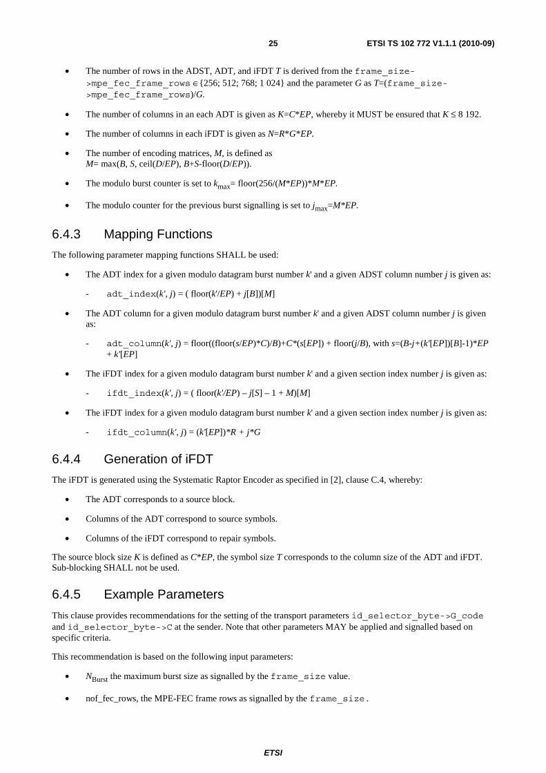
ETSI TS 102 772 V1.1.1 (2010-09)25
• The number of rows in the ADST, ADT, and iFDT T is derived from the frame_size->mpe_fec_frame_rows ∈{256; 512; 768; 1 024} and the parameter G as T=(frame_size->mpe_fec_frame_rows)/G.
• The number of columns in an each ADT is given as K=C*EP, whereby it MUST be ensured that K ≤ 8 192.
• The number of columns in each iFDT is given as N=R*G*EP.
• The number of encoding matrices, M, is defined as M= max(B, S, ceil(D/EP), B+S-floor(D/EP)).
• The modulo burst counter is set to kmax= floor(256/(M*EP))*M*EP.
• The modulo counter for the previous burst signalling is set to jmax=M*EP.
6.4.3 Mapping Functions
The following parameter mapping functions SHALL be used:
• The ADT index for a given modulo datagram burst number k' and a given ADST column number j is given as:
- adt_index(k', j) = ( floor(k'/EP) + j[B])[M]
• The ADT column for a given modulo datagram burst number k' and a given ADST column number j is given as:
- adt_column(k', j) = floor((floor(s/EP)*C)/B)+C*(s[EP]) + floor(j/B), with s=(B-j+(k'[EP])[B]-1)*EP + k'[EP]
• The iFDT index for a given modulo datagram burst number k' and a given section index number j is given as:
- ifdt_index(k', j) = ( floor(k'/EP) – j[S] – 1 + M)[M]
• The iFDT index for a given modulo datagram burst number k' and a given section index number j is given as:
- ifdt_column(k', j) = (k'[EP])*R + j*G
6.4.4 Generation of iFDT
The iFDT is generated using the Systematic Raptor Encoder as specified in [2], clause C.4, whereby:
• The ADT corresponds to a source block.
• Columns of the ADT correspond to source symbols.
• Columns of the iFDT correspond to repair symbols.
The source block size K is defined as C*EP, the symbol size T corresponds to the column size of the ADT and iFDT. Sub-blocking SHALL not be used.
6.4.5 Example Parameters
This clause provides recommendations for the setting of the transport parameters id_selector_byte->G_code and id_selector_byte->C at the sender. Note that other parameters MAY be applied and signalled based on specific criteria.
This recommendation is based on the following input parameters:
• NBurst the maximum burst size as signalled by the frame_size value.
• nof_fec_rows, the MPE-FEC frame rows as signalled by the frame_size.

ETSI
ETSI TS 102 772 V1.1.1 (2010-09)26
• r the target code rate between 0 and 1.
• EP the encoding frequency.
• KMAX the maximum number of columns per ADT with KMAX = 8192 according to the maximum systematic
index in [2], clause C.5.
• KMIN the minimum number of columns per ADT with KMIN = 4 according to the minimum systematic index
in [2], clause C.5.
• KTARGET the target number of columns per ADT.
• TMIN the minimum symbol size for the ADT.
Then, NADST = ceil(r* NBurst) is the expected maximum ADST size.
Then, T = max{TMIN, mini=0,1,2…,,7{ G=R/2i | (EP * ceil(NADST/(R/2i)) <= KTARGET) } } is an appropriate symbol size,
i.e. T is selected such that the Raptor source block has at least KTARGET symbols, but the symbol size is always at least
TMIN bytes and divides the number of MPE-FEC frame rows by a power of 2.
Then the proposed parameters are as follows:
• G = nof_fec_rows / T and id_selector_byte->G_code = log2(G).
• C = ceil(NADST/T) and id_selector_byte->C = C.
Recommended settings for the input parameters are KTARGET = 2 048 and TMIN=32.
Assume a frame_size=0x03 with NBurst=2 048 kbits and nof_fec_rows=1 024, then the above algorithm results in the
following parameter settings.
Table 12: Recommended parameter settings for frame_size=0x03
EP=1 EP=4 EP=8 EP=16 EP=32 C G C G C G C G C G
r=7/8 3584 16 896 4 224 1 448 2 224 1 r=3/4 3072 16 768 4 192 1 384 2 192 1 r=2/3 2730 16 682 4 170 1 341 2 170 1 r=1/2 2048 16 512 4 128 1 256 2 128 1

ETSI
ETSI TS 102 772 V1.1.1 (2010-09)27
Annex A (informative): Receiver operation
A.1 Introduction In this clause we give informative background on how an MPE-IFEC decoder compliant to the coding profiles defined in clauses 6.3 and 6.4 could be implemented:
• We give a general process overview.
• Then we give more details on particular steps of this process:
- parameters derivation from the time_slice_fec_descriptor;
- burst number detection;
- section reception;
- padding ADST;
- main options in the decoding process.
A.2 General Process The sender operation takes as its input the sections received in one time-slice burst and generates at its output datagram bursts that contains a sequence of datagram. The basic steps of an example receiver operation are shown in figure 6.
ADT M-1FDT M-1
Time SliceBurst
MPE datasection
MPE iFECsection
ADST
HMPE data
sectionMPE data
section
MPE iFECsection
PaddingInformation
ADST
ADT 1 FDT 1ADT 0 FDT 0
DatagramBurst
Burst NumberDetection
HHMPE iFEC
sectionMPE-FECDecoding
Figure A.1: Example Receiver Operation
Assume that we have detected the reception of a time-slice burst that MAY contain:
• None, one or several MPE data sections;
• None, one or several MPE-FEC sections;
• None, one, or several MPE-IFEC sections.
ETSI
ETSI TS 102 772 V1.1.1 (2010-09)28
In case that MPE data sections are detected to be missing, and if MPE-FEC sections for this time-slice burst have been received, an MPE-FEC decoding MAY be initiated to recover the MPE data sections for this time-slice burst. In any case, even if everything is correct, the following IFEC decoding process should be started because the data can be used to correct other burst.
The following steps are given for information; other alternatives MAY be given to optimize display time (e.g. fast zapping):
1) Detect current burst number; different techniques are presented in clause A.4.
2) Use received IFEC sections to perform IFEC decoding; this is presented in clause A.7. If a combination of ADT and iFDT has sufficient data to recover, an ADT MAY be recovered and corresponding datagram bursts MAY be recovered.
3) Use received MPE section and, using ADST function, map them onto the ADTs; this is detailed in clauses A.5 and A.6.
4) Go to 0.
When one or several successive complete burst losses happen, it MAY be impossible to detect burst numbering straight away. When this is possible (for instance when another burst is received and the loss is detected) then step 2 is applied for each previously lost burst.
Usually one IFEC section is enough to reconstruct the burst number, reconstruct some padding information, and to insert the IFEC section parity bytes in the relevant positions in the iFDTs (see clause A.5 "section reception").
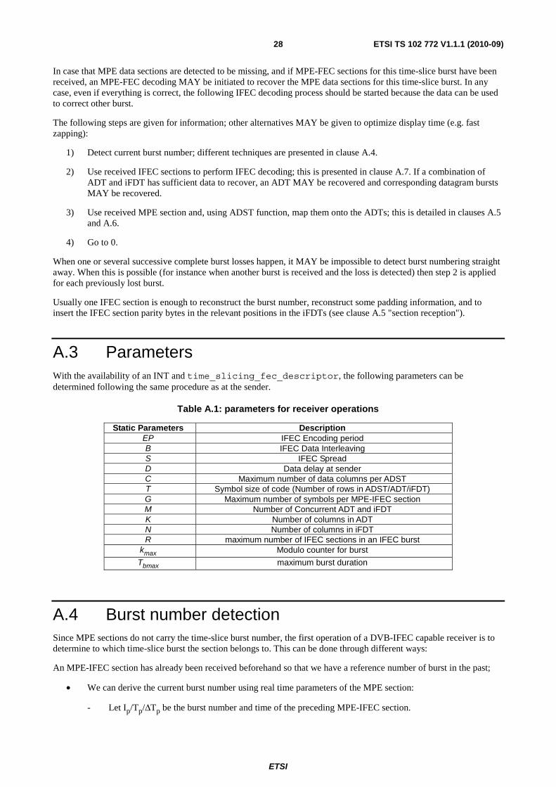
A.3 Parameters With the availability of an INT and time_slicing_fec_descriptor, the following parameters can be determined following the same procedure as at the sender.
Table A.1: parameters for receiver operations
Static Parameters Description EP IFEC Encoding period B IFEC Data Interleaving S IFEC Spread D Data delay at sender C Maximum number of data columns per ADST T Symbol size of code (Number of rows in ADST/ADT/iFDT) G Maximum number of symbols per MPE-IFEC section M Number of Concurrent ADT and iFDT K Number of columns in ADT N Number of columns in iFDT R maximum number of IFEC sections in an IFEC burst
kmax Modulo counter for burst
Tbmax maximum burst duration
A.4 Burst number detection Since MPE sections do not carry the time-slice burst number, the first operation of a DVB-IFEC capable receiver is to determine to which time-slice burst the section belongs to. This can be done through different ways:
An MPE-IFEC section has already been received beforehand so that we have a reference number of burst in the past;
• We can derive the current burst number using real time parameters of the MPE section:
- Let Ip/Tp/ΔTp be the burst number and time of the preceding MPE-IFEC section.

ETSI
ETSI TS 102 772 V1.1.1 (2010-09)29
- Let In/Tn/ΔTn be the burst number and time of the following MPE-IFEC section.
- Let T and ΔT the time and delta-t information of the current MPE section:
MPE-OFECp MPEc
Burst Ip
MPE-OFECn
Burst In
Tp+ΔTpTp
ΔTp
T
ΔT
T+ΔT Tn
ΔTn
Tn+ΔTn
Burst ?
Figure A.2: Burst numbering, general case
• We are looking for the current burst number:
- If (Ip==In) burst_number=I=Ip=In;
- Otherwise, the result MAY be based on some timing heuristic:
� By definition, Tp<T and T<Tn;
� If Tp+ΔTp<T and Tn<T+ΔT THEN I=In;
MPE-OFECp MPE c
Burst Ip
MPE-OFECn
Burst In
Tp+ΔTpTp
ΔTp
T
ΔT
T+ΔT
Tn
ΔTp
Tn+ΔTn
?=In
Figure A.3: Burst numbering, case of next burst
� ELSE T<Tp+ΔTp THEN I=Ip.
MPE-OFECp MPE c
Burst Ip
MPE-OFECn
Burst In
Tp+ΔTp
Tp
ΔTp
T
ΔT
T+ΔT Tn
ΔTp
Tn+ΔTn
Burst ?
Figure A.4: Burst numbering, case of previous burst
� ELSE IGNORE that MPE section for MPE-IFEC decoding.
- Obviously, the discovery of the I=Ip can be achieved only if there are MPE-IFEC sections preceding the
MPE data sections, the latter being completely implementation dependent.

ETSI
ETSI TS 102 772 V1.1.1 (2010-09)30
A.5 Section Reception Once the burst numbering has been done, it is possible to place each received section inside their ADT or iFDT:
• MPE-IFEC sections:
- Each MPE-IFEC section carries a section_number that enables to position this IFEC section inside one iFDT according to the algorithm described in clause 4.5.
- Note that in any case (and contrary to MPE-FEC), even if all sections in current datagram burst have been received correctly, the receiver needs ro continue to receive remaining MPE-IFEC sections since they can be used in different FDTs than the ones used to decode the current ADST, or they could be used in the same FDTs as those used to decode the current ADST but for decoding other more erroneously received ADSTs.
- The number of received sections in the current burst cannot exceed the signalled fec_burst_size in every IFEC section received. If there are fewer sections delivered, this means that some IFEC sections have been lost.
- When reception is over, in case one section is missing, there MAY be a decision from the receiver with regard to decoding because it has learnt the total number of IFEC columns transmitted for an iFDT using max_iFDT_column signalled in the sections carrying the columns of this iFDT. If losses are too severe on the ADT, it MAY be impossible to decode.
- The IFEC sections carry also prev_burst_size information enabling to delineate the padding part within the previously received burst.
• MPE sections:
- Each correctly received (i.e. with a correct CRC32) MPE-section can be placed at the right position inside the ADST since each MPE section carries in the section header a start address for the payload. The receiver will then be able to put the received datagram in the right byte positions in the ADST and mark these positions as "reliable".
- When all possible MPE sections correctly received have been processed, the padding or erased bytes are added according to clause A.6. Erased bytes are positioned as unreliable whereas padding bytes are positioned as reliable. Then the C columns are interleaved inside their relevant ADT using same algorithm as in the sender described in clause 4.6.
A.6 Padding in ADST mapping The receiver introduces the number of padding columns during the ADST mapping by marking these padding bytes as reliable. Some of the following guidelines MAY be used to recover the padding information whereby the description is supported by some examples in figure 10:
• If the receiver has received the last MPE section of the time-slice burst correctly, it can mark any remaining padding bytes as reliable (case k'-2 in figure 10).
• If the receiver did not receive the last section correctly, it has to check if the prev_burst_size or this burst is available; if yes, this implies that all byte positions after the last correctly received section until the burst size signal by prev_burst_size are lost data and will mark them as unreliable (case k'-1).
• If the receiver has received neither the signalling of the padding size using prev_burst_size, nor the last MPE section, then it will have to mark all bytes positions after the last correctly received section as lost data and mark the corresponding byte positions as unreliable (case k'-3).
• If there are missing sections before the last section, the receiver can set as unreliable the corresponding bytes (case k'-4).

ETSI
ETSI TS 102 772 V1.1.1 (2010-09)31
iFE
C(k
’,0)
iFE
C(k
’,1)
iFE
C(k
’,2)
…
iFE
C(k
’,k)
MP
E la
st_s
ectio
n_nu
mbe
r
MP
E la
st_s
ectio
n_nu
mbe
r
MP
E
MP
E la
st_s
ectio
n_nu
mbe
r
MP
E la
st_s
ectio
n_nu
mbe
r
Los
t MPE
MP
E
Unreliable (lost MPE or unknown)
Padding from last_section_number
Well received (from MPE header)Padding from PREV_BURST_SIZE
k’-1k’-2k’-3k’-4
? ?
k’
Figure A.5: Padding strategy
A.7 Decoding The scope of this clause is to exemplify typical receiver procedures for the reconstruction of a flow of IP datagram bursts from a sequence of received time-slice bursts. The reference receiver presented in this clause is designed as to meet minimum performance requirement and therefore its structure is intentionally kept simple. Specific implementations MAY differ in some implementation aspects, but they still can be considered fully compliant as long as they fulfil at least the minimum performance of the reference receiver.
A.7.1 Input The IFEC decoding attempts to recover an ADT with use of the information in the ADT, the padding information in the ADT, as well as the corresponding iFDT. The ADT consists of K columns and T rows, the iFDT consists of R*EP columns and T rows. Only CRC32 valid sections are positioned: all the bytes that constitute the section are signalled as unreliable; in order to save memory, each column in the ADT is MAY be marked as unreliable, if any of the T bytes in the column is erased. Then, if the total number of non-erased columns in ADT and iFDT is at least K, IFEC decoding is applied.
A.7.2 RS decoding For the case of RS codes, at every burst, one (ADT , iFDT) couple can be decoded using the same principles as for MPE-FEC presented in [1], clause 9.3.3.

ETSI
ETSI TS 102 772 V1.1.1 (2010-09)32
A.7.3 Raptor decoding For the case of Raptor codes, an appropriate decoding algorithm is provided in [2], clause C.7, whereby:
• The source block is determined by the number of symbols K and the symbol size T.
• The ensemble of encoding symbols consists of:
- The non-erased columns in the ADT, whereby the encoding symbol ID (ESI) corresponds column number in the ADT.
- The available columns in the iFDT, whereby the ESI corresponds to the column number in iFDT plus K.
If IFEC decoding is successful, the ADT columns are updated by the reconstructed encoding symbols.
A.7.4 Output Depending on the number of erroneous bytes after frame decoding, several options are possible:
• All missing bytes have been corrected, all datagrams are forwarded to the application.
• Some bytes have not been corrected; only correct datagrams are forwarded to the application.
• Some bytes have not been corrected; the erroneous datagrams are also forwarded to the application.

ETSI
ETSI TS 102 772 V1.1.1 (2010-09)33
History
Document history
V1.1.1 September 2010 Publication