ts-120-mpp1 - ameradio.com€¦ · the ts-120 offers ani & emergency ani in motorola’s...
TRANSCRIPT

1
TS-120-MPP1
Multi-Format ANI Encoder with Lone Worker & Man-Down
Manual Revision: 2013-03-01
Covers Software Revisions: VS-1XXX: 01.53.00 & Higher
Covers Software Revisions: VS-MPP1: D & Higher
This manual supports the following radios:
North America: HT-750, HT-1250, HT-1250-LS+, MTX-850-LS, MTX-8250-LS, PR-860 EMEA Region: GP-140, GP-340, GP-360, GP-380, GP-640, GP-680 Asia: GP-328, GP-328-LS, GP-329, GP-338, GP-338-LS, GP-339, PTX-700, PTX-760 Latin America: PRO-5150, PRO-5350, PRO-5450, PRO-7150, PRO-7350, PRO-7450
2
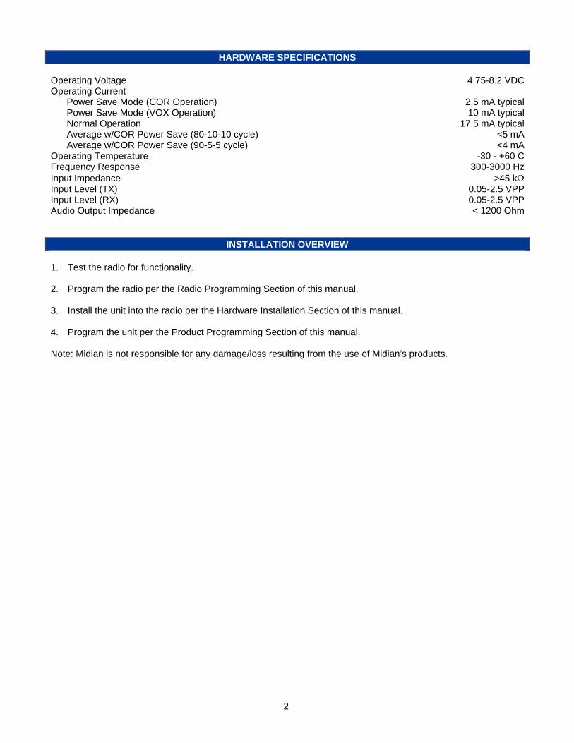
HARDWARE SPECIFICATIONS Operating Voltage 4.75-8.2 VDC Operating Current Power Save Mode (COR Operation) 2.5 mA typical Power Save Mode (VOX Operation) 10 mA typical Normal Operation 17.5 mA typical Average w/COR Power Save (80-10-10 cycle) <5 mA Average w/COR Power Save (90-5-5 cycle) <4 mA Operating Temperature -30 - +60 C Frequency Response 300-3000 Hz Input Impedance >45 k Input Level (TX) 0.05-2.5 VPP Input Level (RX) 0.05-2.5 VPP Audio Output Impedance < 1200 Ohm
INSTALLATION OVERVIEW
1. Test the radio for functionality. 2. Program the radio per the Radio Programming Section of this manual. 3. Install the unit into the radio per the Hardware Installation Section of this manual. 4. Program the unit per the Product Programming Section of this manual. Note: Midian is not responsible for any damage/loss resulting from the use of Midian’s products.

3
GENERAL INFORMATION Midian’s TS-120 Series products encode ANI and Emergency ANI to display on ANI display decoder to identify which field unit is being keyed. The following is a list of benefits provided by ANI systems: Allows dispatchers to know who he or she is talking to. Identify system abusers. Identify emergency conditions. Assign calls fairly. The TS-120 offers ANI & Emergency ANI in Motorola’s MDC-1200, Kenwood’s FleetSync, Harris’ G-Star (aka GE-Star), DTMF and 5-tone. The TS-120 can be used with Midian’s ADD, CAD, DDU and TRC Series products for monitoring ANI and ENI transmissions. The TS-120 also offers Lone Worker and Man-Down features. If the unit does not receive any user interaction (PTT button, Lone Worker Reset button or movement) for a programmable period of time the unit can key the radio and send the Emergency ANI. .
4
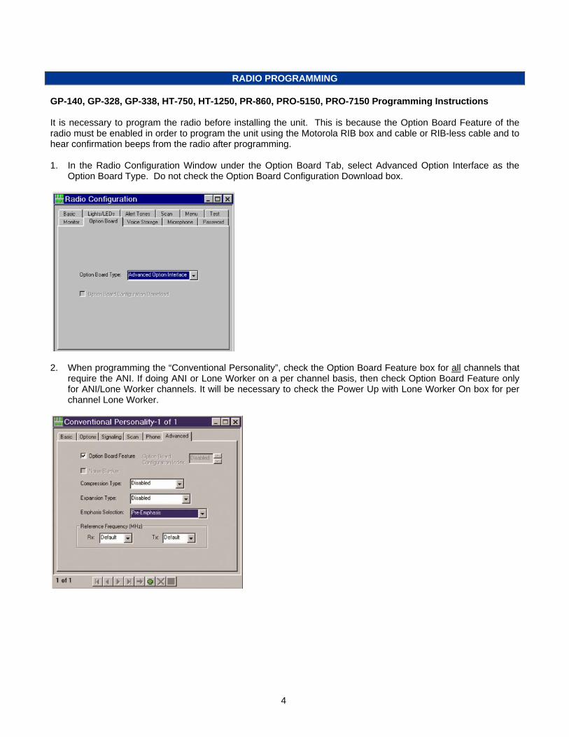
RADIO PROGRAMMING GP-140, GP-328, GP-338, HT-750, HT-1250, PR-860, PRO-5150, PRO-7150 Programming Instructions It is necessary to program the radio before installing the unit. This is because the Option Board Feature of the radio must be enabled in order to program the unit using the Motorola RIB box and cable or RIB-less cable and to hear confirmation beeps from the radio after programming. 1. In the Radio Configuration Window under the Option Board Tab, select Advanced Option Interface as the
Option Board Type. Do not check the Option Board Configuration Download box.
2. When programming the “Conventional Personality”, check the Option Board Feature box for all channels that
require the ANI. If doing ANI or Lone Worker on a per channel basis, then check Option Board Feature only for ANI/Lone Worker channels. It will be necessary to check the Power Up with Lone Worker On box for per channel Lone Worker.

5
GP-329, GP-339, GP-340, GP-360, GP-380 Programming Instructions It is necessary to program the radio before installing the unit. This is because the Option Board Feature of the radio must be enabled in order to program the unit using the Motorola RIB box and cable or RIB-less cable and to hear confirmation beeps from the radio after programming the unit. 1. In the Per Radio Miscellaneous Window under the Global Tab, select “Advanced” as the “Option Board Type”.
2. For each personality, under the Miscellaneous tab, the “Option Board” must be enabled. Check the Option
Board box for all channels that require the ANI. If doing ANI or Lone Worker on a per channel basis, then check Option Board Feature only for ANI/Lone Worker channels. It will be necessary to check the Power Up with Lone Worker On box for per channel Lone Worker.
6
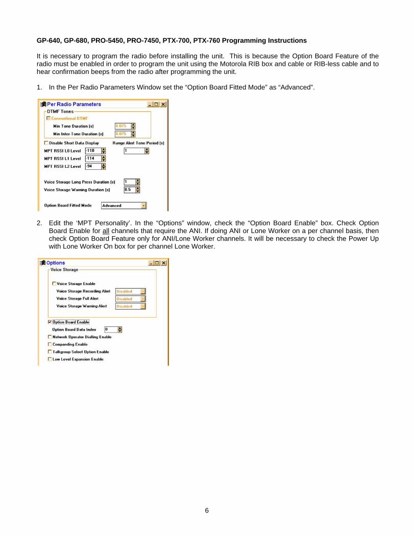
GP-640, GP-680, PRO-5450, PRO-7450, PTX-700, PTX-760 Programming Instructions It is necessary to program the radio before installing the unit. This is because the Option Board Feature of the radio must be enabled in order to program the unit using the Motorola RIB box and cable or RIB-less cable and to hear confirmation beeps from the radio after programming the unit. 1. In the Per Radio Parameters Window set the “Option Board Fitted Mode” as “Advanced”.
2. Edit the ‘MPT Personality’. In the “Options” window, check the “Option Board Enable” box. Check Option
Board Enable for all channels that require the ANI. If doing ANI or Lone Worker on a per channel basis, then check Option Board Feature only for ANI/Lone Worker channels. It will be necessary to check the Power Up with Lone Worker On box for per channel Lone Worker.

7
3. If using conventional channels, edit the ‘Conventional Personality Data’. In the “Conventional Personality”
window, check the “Option Board Enable” box.

8
GP-328-LS, GP-338-LS, HT-1250-LS+, MTX-850-LS, MTX-8250-LS, PRO-5350, PRO-7350 Programming Instructions It is necessary to program the radio before installing the unit. This is because the Option Board Feature of the radio must be enabled in order to program the unit using the Motorola RIB box and cable or RIB-less cable and to hear confirmation beeps from the radio after programming the unit. 1. In the Radio Configuration Window under the Option Board Tab, select Advanced Option Interface as the
Option Board Type. Do not check the Option Board Configuration Download box.
2. When programming the “Conventional Personality”, check the Option Board Feature box for all channels that
require the ANI. If doing ANI or Lone Worker on a per channel basis, then check Option Board Feature only for ANI/Lone Worker channels. It will be necessary to check the Power Up with Lone Worker On box for per channel Lone Worker.
9
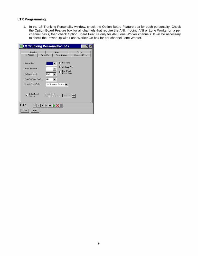
LTR Programming:
1. In the LS Trunking Personality window, check the Option Board Feature box for each personality. Check the Option Board Feature box for all channels that require the ANI. If doing ANI or Lone Worker on a per channel basis, then check Option Board Feature only for ANI/Lone Worker channels. It will be necessary to check the Power Up with Lone Worker On box for per channel Lone Worker.
10
HARDWARE INSTALLATION
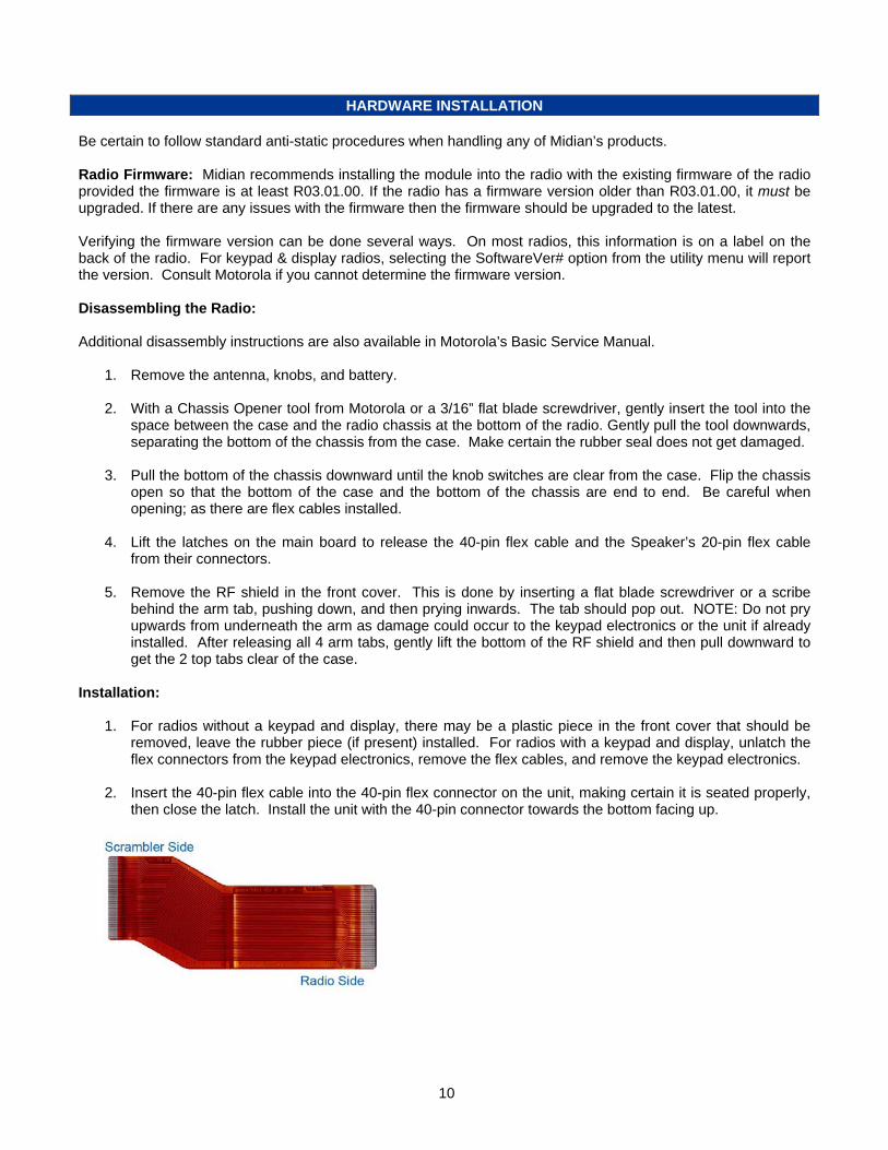
Be certain to follow standard anti-static procedures when handling any of Midian’s products. Radio Firmware: Midian recommends installing the module into the radio with the existing firmware of the radio provided the firmware is at least R03.01.00. If the radio has a firmware version older than R03.01.00, it must be upgraded. If there are any issues with the firmware then the firmware should be upgraded to the latest. Verifying the firmware version can be done several ways. On most radios, this information is on a label on the back of the radio. For keypad & display radios, selecting the SoftwareVer# option from the utility menu will report the version. Consult Motorola if you cannot determine the firmware version. Disassembling the Radio: Additional disassembly instructions are also available in Motorola’s Basic Service Manual.
1. Remove the antenna, knobs, and battery.
2. With a Chassis Opener tool from Motorola or a 3/16” flat blade screwdriver, gently insert the tool into the space between the case and the radio chassis at the bottom of the radio. Gently pull the tool downwards, separating the bottom of the chassis from the case. Make certain the rubber seal does not get damaged.
3. Pull the bottom of the chassis downward until the knob switches are clear from the case. Flip the chassis
open so that the bottom of the case and the bottom of the chassis are end to end. Be careful when opening; as there are flex cables installed.
4. Lift the latches on the main board to release the 40-pin flex cable and the Speaker’s 20-pin flex cable
from their connectors.
5. Remove the RF shield in the front cover. This is done by inserting a flat blade screwdriver or a scribe behind the arm tab, pushing down, and then prying inwards. The tab should pop out. NOTE: Do not pry upwards from underneath the arm as damage could occur to the keypad electronics or the unit if already installed. After releasing all 4 arm tabs, gently lift the bottom of the RF shield and then pull downward to get the 2 top tabs clear of the case.
Installation:
1. For radios without a keypad and display, there may be a plastic piece in the front cover that should be removed, leave the rubber piece (if present) installed. For radios with a keypad and display, unlatch the flex connectors from the keypad electronics, remove the flex cables, and remove the keypad electronics.
2. Insert the 40-pin flex cable into the 40-pin flex connector on the unit, making certain it is seated properly,
then close the latch. Install the unit with the 40-pin connector towards the bottom facing up.

11
3. Reinstall the display flex and close the latch. Insert the other side of the 40-pin flex cable into the 40-pin flex connector on the radio’s main board. Reinstall the speaker flex and close the latch.
Reassembling the Radio: Additional assembly instructions are also available in Motorola’s Basic Service Manual.
1. Reinstall the RF shield over the Midian board, by first inserting the 2 top tabs and then snapping the 4 arm tabs back into place with a small flat blade screwdriver. Be certain the board is squarely aligned and not to damage the flex cables. The RF shield may bulge slightly in the center; this is normal.
2. Place the chassis into the front cover. Be certain the O-ring seal is properly aligned and does not get damaged. Push the chassis up into the case and then push the bottom down until it snaps.
3. Replace the knobs, antenna and battery.

12
PRODUCT PROGRAMMING Install the Midian programming software if you have not done so already. The units are programmed through the radio using the Motorola RIB box and cable or RIBless cable and Midian’s MPS software. Start the Midian programming software. From the product selection screen in the software, locate and select the desired unit model and click OK. Configure the programming software by selecting File->Preferences and make certain there is a check mark next to ‘Rib Box Enable’ by clicking on it. Also select the appropriate COM port. Set the parameters of the software to fit the application. If any clarifications on a feature are required, move the mouse cursor over the feature name until the question mark appears and right click, an on-line help for that feature will be shown. The programming software always defaults to “MDC Portable” as the radio type. On the basic settings tab it is necessary to select the proper radio type. After entering the parameters, save the file by going to File - Save As. Enter the file name in the File Name block and click Save. Saving the file will allow for quick and easy reprogramming of units. Turn power on to the radio and then the RIB. Click ProgramUnit! in the software. You will hear 1-3 beeps from the radio if programmed successfully. To read the parameters from the unit, Click on ReadUnit!. The radio and RIB should be powered down for 3 seconds after reading or programming.
13
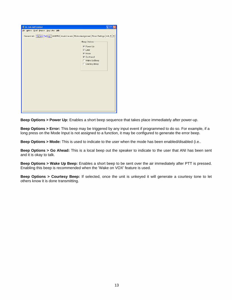
Beep Options > Power Up: Enables a short beep sequence that takes place immediately after power-up. Beep Options > Error: This beep may be triggered by any input event if programmed to do so. For example, if a long press on the Mode Input is not assigned to a function, it may be configured to generate the error beep. Beep Options > Mode: This is used to indicate to the user when the mode has been enabled/disabled (i.e.. Beep Options > Go Ahead: This is a local beep out the speaker to indicate to the user that ANI has been sent and it is okay to talk. Beep Options > Wake Up Beep: Enables a short beep to be sent over the air immediately after PTT is pressed. Enabling this beep is recommended when the 'Wake on VOX' feature is used. Beep Options > Courtesy Beep: If selected, once the unit is unkeyed it will generate a courtesy tone to let others know it is done transmitting.
14
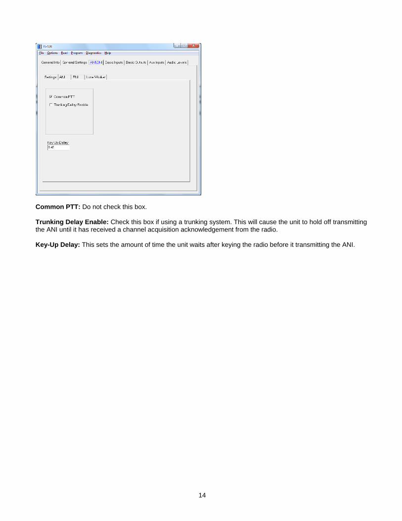
Common PTT: Do not check this box. Trunking Delay Enable: Check this box if using a trunking system. This will cause the unit to hold off transmitting the ANI until it has received a channel acquisition acknowledgement from the radio. Key-Up Delay: This sets the amount of time the unit waits after keying the radio before it transmitting the ANI.
15
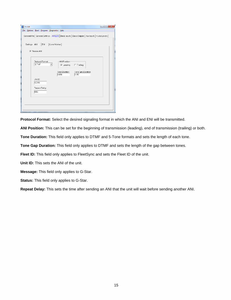
Protocol Format: Select the desired signaling format in which the ANI and ENI will be transmitted. ANI Position: This can be set for the beginning of transmission (leading), end of transmission (trailing) or both. Tone Duration: This field only applies to DTMF and 5-Tone formats and sets the length of each tone. Tone Gap Duration: This field only applies to DTMF and sets the length of the gap between tones. Fleet ID: This field only applies to FleetSync and sets the Fleet ID of the unit. Unit ID: This sets the ANI of the unit. Message: This field only applies to G-Star. Status: This field only applies to G-Star. Repeat Delay: This sets the time after sending an ANI that the unit will wait before sending another ANI.

16
Protocol Format: This displays the format selected on the ANI tab. Fleet ID: This field only applies to FleetSync and sets the Fleet ID for the ENI. Unit ID: This sets the Emergency ANI of the unit. Message: This field only applies to G-Star. Status: This field only applies to G-Star. Transmit Forever: If selected the ENI will transmit continuously at the repeat interval until canceled. Transmit Count: This sets the number of times the ENI will be sent. Repeat Interval: This sets the time between ENI transmissions. PTT Resets/Cancels ENI: If selected, pressing the PTT button will either reset the Lone Worker’s Transmit Delay time or cancel the transmission of the ENI. Live Mic Enable: If selected the unit will enable the mic of the radio to transmit mic audio to the dispatcher. Revert to Clear: Currently not used. Locator Tone Enable: If selected the unit will emit tones out the radio’s speaker.

17
Transmit Delay: In Lone Worker mode, if the user does not interact with the radio before this amount of time passes, the ENI sequence will be transmitted. This time is in seconds. Warning Tone Enable: This will generate a tone sequence to alert the user the ENI is about to be transmitted. Warning Tone Delay: In Lone Worker mode, if the user does not interact with the radio before this amount of time passes, the emergency warning tone will be sounded. This amount of time must be less than that of the Transmit Delay for the warning tone to be sounded. Also, the Warning Tone Enable box must be checked for the tone to be sounded. For example, based on the screen shown above after 105 seconds of no activity the unit will generate warning tones. The user then has 15 seconds to interact with the radio to keep the Transmit Delay time of 120 seconds expiring and the ENI being transmitted. Continuous Warning Enable: This will generate a constant tone to alert the user the ENI is about to be transmitted. Power-up with Lone Worker on: If checked the unit will be in Lone Worker mode when the radio is turned on. This eliminates the need for the user to use the mode input to turn the Lone Worker mode on. Motion Resets Delay Timers: The unit can then use the accelerometer to detect motion based on the Motion Sensitivity setting to determine if the user is in distress in addition to requiring interaction with the radio. Motion Sensitivity: This sets a level of motion required to reset the Transmit Delay timer. Some work environments may have an inherent level of motion that would be detected by lower settings of the accelerometer, so a higher level of sensitivity might be needed. Midian recommends experimenting to determine the best sensitivity setting for the work environment.

18
Tones > Beep Volume: Adjust the slider for the desired beep volume. This level is expressed as a percentage of max voice audio level. Tones > Over-The-Air-Signal Modulation: Adjust the slider for the desired beep volume. This level is expressed as a percentage of max voice audio level.
Please see the Audio Levels Alignment section for details on this tab.
19
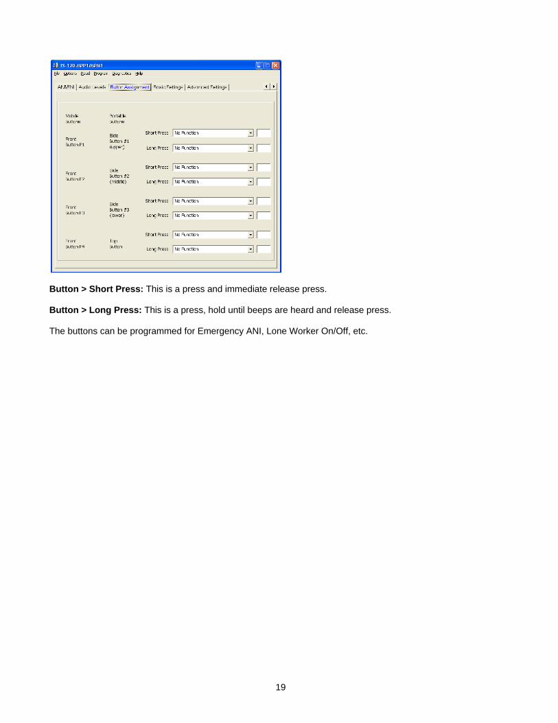
Button > Short Press: This is a press and immediate release press. Button > Long Press: This is a press, hold until beeps are heard and release press. The buttons can be programmed for Emergency ANI, Lone Worker On/Off, etc.

20
Radio Type: Select from the list the Radio Type that matches your radio. For example if the radio is an HT-750 or GP-140 you would select Conventional MDC Portable or if the radio is a PTX-760, GP-680 or PRO-7450 you would select MPT Portable. Enable Mode LED: Future Use. Enable LCD Messages: Future Use. Use Accessory Pin for Mode Input (mobile only): If desired the unit can be enabled/disabled using an input from the rear accessory connector of the mobile radio. Use Accessory Pin for Emergency Input (mobile only): Future Use.
The “Option Board Always Controls PTT” box must be checked. Otherwise please only adjust the parameters of this screen when advised to by Midian.

21
AUDIO LEVELS ALIGNMENT
This section describes how to determine and set the audio levels. Audio Levels Overview: To ensure the best audio quality, the unit must be configured to match the audio levels used by the radio. The unit uses programmable gain amplifiers to accomplish this. Determining the gain settings for these amplifiers is an involved process, so Midian simplified this process by developing an algorithm that requires the technician to make only four voltage measurements. From these four measurements, all of the many internal settings are determined. Still, getting the best audio quality will likely require a bit of trial and error. The unit only has control of audio voltage levels, not input and output impedances. These impedances can dramatically influence the levels. The Four Voltage Measurements: An oscilloscope and a communications test set/service monitor are required for the measurements. It is recommended that the measurements be recorded in units of mV peak-to-peak. Each measurement must be taken with system modulation at either 60% or 100%, but Midian recommends using 60% A method for controlling transmit modulation is required for accurate measurements in the TX mode. A small speaker held in place near the microphone by a rubber band can serve this purpose in most cases. Use a sine-wave generator to inject a 1000 Hz tone into the speaker. Adjust the output of the sine wave generator so that the transmitter produces 60% of rated modulation while PTT is pressed. Note that if the audio source (such as a speaker) is moved even slightly, the TX modulation may change significantly. Care must be taken to avoid changing the TX modulation while taking the measurements. The first two measurements must be taken using a radio that has not been modified. The 2nd two measurements require that the unit is installed and power is applied to the radio. These measurements must be taken within 15 seconds of powering on the radio/unit. This is because the unit may enter power saving mode after that time. Measurements made while the unit is in power saving mode will not be valid. The unit ships with the power save feature enabled by default. The power save feature can be disabled via the KL-3 programming software so that it will not interfere with taking measurements, if desired. Please note that the levels provided to the option board are different between narrow band and wide band. 1. TX Input: The goal of this procedure is to determine the audio level that the unit will see at the TX audio
pickup point after it is installed. The unit must be installed and powered-on while making this measurement. Use the TX Alignment Set-Up procedure and measure the audio level at TP1 on the unit.
2. RX Input: The goal of this procedure is to determine the audio level that the unit will see at the RX audio
pickup point after it is installed. The unit must be installed and powered-on while making this measurement. Use the TX Alignment Set-Up procedure and measure the audio level at TP2 on the unit.
3. In the programming software under audio levels set the TX In to the same level as measured in step 1 and for
a preliminary adjustment set the TX Out for the same level. Set the RX In to the same level as measured in step 2 and for a preliminary adjustment set the RX Out for the same level. Program the unit.
4. RX Output: The goal of this procedure is to determine the audio level that would normally appear at the RX
audio insertion point in an unmodified radio. Using the same RX Alignment Set-Up procedure verify the audio level at the speaker is still at the same level measured initially in the RX Alignment Set-Up procedure. If not adjust the RX Out level accordingly.
5. TX Output: The goal of this procedure is to determine the audio level that would normally appear at the TX
audio insertion point in an unmodified radio. Using the same TX Alignment Set-Up procedure verify the modulation is still at 60%, if not adjust the TX Out level accordingly.

22
Programming the Audio Levels: After determining the audio levels at the audio hookup points, it will be necessary to program the unit to match these levels. In the programming software, there is a slider control on the Audio Levels Screen for each of the of four audio hookup points. Locate the column that corresponds to the modulation and units of measurement for each of the audio hookup points. Adjust the slider bar such that the value appearing in the appropriate column matches what was measured as closely as possible. Midian recommends the following values based on 60% modulation in mVpp: Radio Model RX In TX In RX Out TX Out GP-140, GP-328, GP-338, HT-750, HT-1250, PRO-5150, PRO-7150 798 108 168 108 PR-860 GP-329, GP-339, GP-340, GP-360, GP-380 GP-328-LS, GP-338-LS, HT-1250-LS+, MTX-850-LS, MTX-8250-LS PRO-5350, PRO-7350
678 138 150 138
GP-640, GP-680, PRO-5450, PRO-7450, PTX-700, PTX-760

23
OPERATION
ANI Encode: When the PTT button is pressed, the unit will assert the PTT Output and send the programmed ANI tones out the TX Tone Output. ENI Encode: When the Emergency input is activated, the unit will assert the PTT Output and send the programmed Emergency ANI tones out the TX Tone Output. Lone Worker Enable: The Lone Worker feature can be enabled upon power up or using the Mode Input or Emergency Input. Lone Worker Reset: If the Lone Worker feature is being used, pressing the PTT or pressing the button assigned to Lone Worker Reset will reset the Transmit Delay timer. If the Warning Tone Delay time expires the unit will generate warning tones to indicate to the user that the Lone Worker feature is about to send an ENI if the unit does not see PTT or Lone Worker Reset activity. If the Transmit Delay time then expires the unit will send the ENI.
TECHNICAL NOTES
Radio Compatibility: Midian has taken the utmost care to ensure the option board integrates into the radio with minimal impact to the features of the radio. However, some features may not be available in the radio when an option board is used. If a feature is not available, please contact Midian to see if the feature can be added. Radio Firmware: Midian recommends installing the module into the radio with the existing firmware of the radio provided the firmware is at least R03.01.00. If the radio has a firmware version older than R03.01.00, it must be upgraded. If there are any issues with the firmware then the firmware should be upgraded to the latest. However, it should be noted that occasionally firmware updates may cause a conflict with proper option board/radio communications. This may appear that the unit is not working properly, but it is a conflict in the serial communication between the option board and radio. For installation into MPT-1327 capable portable radios Midian recommends a minimum radio firmware version of R02.04.00. Firmware versions prior to this did not allow option board operation in both conventional and trunked modes. Option Board Feature: Enabling the option board feature tells the radio to report events such as button press, PTT press, carrier detect, etc. to the option board. This feature enables communication between the option board and the radio. On display models, the following icon appears on the LCD when option board mode is on:

24
MIDIAN CONTACT INFORMATION
MIDIAN ELECTRONICS, INC. 2302 East 22nd Street Tucson, Arizona 85713 USA
Toll-Free: 1-800-MIDIANS Main: 520-884-7981 E-mail: [email protected] Web: HUwww.midians.comU
*
MISO016
SSO15
XTA
L33
HOME035
INDEX036
PHASEB037
PHASEA038
PWMA03
IRQA11
FAULTA012
ANA020
CAN_RX46
AN
A121
RST 2
TCK 39
TMS 40
TDI 41
TDO 42
EX
TAL
32
VSS
31
VSS
13
VSS
10
VSS
45
VC
AP2
17
VC
AP1
43
VDDADC 30
VSSADC 29
VREFIN 26
VREFMID 27
VREFP 28
VD
D_I
O5
VD
D_I
O14
VD
D_I
O34
VD
D_I
O44
TCO 1
PWMA1 4
PWMA2 6
PWMA3 7
PWM
A48
PWMA5 9
MO
SI0
18
SCLK019
ANA222
ANA4 23
ANA524
AN
A625
CAN_TX 47
TC148
U3
P1-
316
P5-113
VD
D42
P3-111
P3-59
P4-54
P4-73
P2-637
P3-78
P2-747
P3-628
P5-224
P3-427
P1-220
VSS18
AGND36
P0-743
P0-146
P2-
548
P0-345
P0-641
P4-1 6P0-544
P2-
31
P2-
12
P0-
038
P0-
440
P0-
239
P2-0 34
P1-4 21
P1-6 22
SMP 7
P2-2 35
P1-1 17
P1-0 19
XRES 29
P3-0 25
P5-0 23P3-2 26
P5-3 12
P3-3 10P4-3 5P1-5 15
P1-7 14
P4-6 33P4-4 32P4-0 30P4-2 31
PAD 49
U1
7427
SH
DN
7
V+
4
CLK
8
IN2 OUT 5
CO
M1
OS
6
V-
3 U4
LMV324-
+
2
31
114
U7:1
LMV324
-
+
6
57U7:2
LMV324
-
+
9
108U7:3
LMV324
-
+
13
1214U7:4
EXT_MIKEJ601:1
VS_CSJ601:2
SW B+J601:3
VDDDJ601:4
VS_AUDSELJ601:5
DIS_INJ601:6
RX_OUTJ601:7
TX_INJ601:8
TX_OUTJ601:9
FLAT_RX_RETJ601:10
OPT_ENAJ601:11
RDYJ601:12
RX_INJ601:13
ONJ601:14
INT_ENT_VddJ601:15
PTT_INJ601:18
VS_INTJ601:20
OFF_BAT_DATA_OUTJ601:23
VS_GAINSELJ601:24
MISOJ601:25
MOSIJ601:26
CLKJ601:38
VS_RACJ601:39
GNDJ601:40
47KR2 +3.3V
*R1
560pC1
+3.3V
560pC2
47KR7
47KR6
5206
IN11
ENA3
GN
D2
RES
4
OUT 5
VR1
5206
IN11
ENA3
GN
D2
RES
4
OUT 5
VR2
5206
IN11
ENA3
GN
D2
RES
4
OUT 5
VR3
560pC4
100KR15
100KR14
+3.3VDD.1uC7
2RR49
2RR50
2RR51
+3.3V
+3.3VA
+3.3VDD
8.2KR16
27KR13
.1uC10
.01uC9
4.7KR8
+3.3V
VAN
.0068uC15
.0068uC16
*C17
56KR18
36KR21
.001uC18
75KR19
VAN
1.2MR20
VAN
10KR9.1u
C12
VAN
100pC14
10K1%R11
10K1%R12
10KR10
3157
Y03
Y11
GN
D2
Z 4
VD
D5
S6
U5
39pC44
+3.3V
+3.3V
.1uC25
.01uC21
2.2uC20
560pC19
3.3KR24
*R17
VAN
TP8
TP18
TP7
TP6
TP17
TP5
TP12
TP3
TP4
TP1
TP2
3.3KR28
.01uC45
2.2uC26
2.2uC27
P4:1
P4:2
P4:3
P4:4
P4:5
P4:6
P3:
1
P3:
2
P3:
3
P3:
4
P3:
5
P3:
6
.1uC28
.1uC29
.1uC30
.1uC31
10uC36
10uC35
10uC32
12pC38
100pC39
32 KHz.Y1
+3.3V
+3.3V
+3.3VDD
+3.3VA
+3.3V
.1uC13
VDDD
.01uC47
PROG_INPROG_INPI
PROG_OUTPROG_OUTPO
4.7KR30
+3.3V
47KR31
+3.3V
VDDD
VDDD
4.7KR55
4.7KR54
100KR34
100KR35
560pC37
.1uC41
10uC40+3.3V
0RL1
SW_B+
SRD_SND
SCK_SND
100pC617
*C48
PTT_OUT
VDDD
0RR32
*C50
*C49
PTT_OUT
*C52
4001Q1
4001Q2
*Q6
0RR52
SB1D1
SB1D2
SB1D4
SB1D3
560pC11
1 2 3 4 5 6
1 2 3 4 5 6
A
B
C
D D
C
B
A
0RR57
0RR58
47KR36 +3.3V
+3.3V
.1uC43
SB1D6
.1uC42
CS1
SO2
SI5
SCK6
VCC 8
HOLD 7
WP 3
GND 4
*U6
.22uC33
22pC24
*C51
CS7
SO12
SI13
SCK14
DVDD 1
INT29 INT18
GND 2
MMA7455L
AVDD 6
GND 5
IADDR0 431011
U10
RESET
4.7uC5
4.7uC53
CP
CJS
2009-03-25 DML
2012-09-04
D-1
1 of 2 7701
MIDIAN ELECTRONICS, INC.DATE:
DESIGN:
DWN BY:
REV:
APPR
COPYRIGHT ©
REV
SHEET PROJECT NUMBER
DOCUMENT NAME
SCHEMATIC2012
TS-120-MPP
NOTE: * = NOT INSTALLED

100KR633
100KR646
100KR632
100KR648
B25Q602
B25Q603
100pC616
VDDD SW_B+
1KR620
1KR621
1KR622
1KR618
1KR619
1KR623
D601 D602 D603 D604 D605 D606
_
B4
\|/
B5
+
B6
P1
B7
P2
B8
P3
B9
1
B10
2
B11
3
B12
4
B13
5
B14
6
B15
7
B16
8
B17
9
B18
*
B19
0
B20
#
B21
ROW_3 ROW_4 ROW_5
COL_5
COL_1 COL_2 COL_3
ROW_5
ROW_4
ROW_3
ROW_2
ROW_1
51.1K1%R601
51.1K1%R602
13K1%R603
13K1%R607
22.1K1%R604
22.1K1%R608
43.2K1%R605
43.2K1%R609
130K1%R606
130K1%R610 *-
+
4
31
25
U602
51.1K1%R611
560K1%R612
1MR613
*C609
VDDD
VDDD
COL_1 COL_2 COL_3 COL_4 COL_5
ROW_1 ROW_2 ROW_3 ROW_5ROW_4
VDDD
SRD_SNDJ602:1
SCK_SNDJ602:2
DB0J602:3
DB1J602:4
DB2J602:5
DB3J602:6
DB4J602:7
DB5J602:8
DB6J602:9
DB7J602:10
A0J602:11
R/WJ602:12
RESETJ602:13
LCD_SELJ602:14
LED_BACKLIGHT_ENABLEJ602:15
GNDJ602:16
VDDDJ602:17
SW_B+J602:18
Y25Q601
47KR649
3.3KR647
LED_ENJ601:22
*R630
*R625
SRD_SND
SCK_SND
DB0J601:29
DB1J601:30
DB2J601:31
DB3J601:32
DB4J601:33
DB5J601:34
DB6J601:35
DB7J601:36
A0J601:37
0RR631
*R638
R/WJ601:27
*R629
SW_B+
100pC610
SW_B+
CSJ601:28
RESETJ601:21
100pC613
KEY_ROWJ601:16
KEY_COLJ601:17
100pC612
100pC611
VDDD
VDDD
100pC615
KEY_INTRPJ601:19
NOTE: * = NOT INSTALLED
D
A
B
C C
D
B
A
61 2 3 4 5
1 2 3 4 5 6
RESET
VO1
Top Pad Solder
VO2
Bottom Pad Solder
VO3
VS1200 Base Board
VO4
VS-1000 MPP Base Board
VO5
Board House Info
CP
CJS
2009-03-25 DML
2012-09-04
D-1
1 of 2 7701
MIDIAN ELECTRONICS, INC.DATE:
DESIGN:
DWN BY:
REV:
APPR
COPYRIGHT ©
REV
SHEET PROJECT NUMBER
DOCUMENT NAME
SCHEMATIC2012
TS-120-MPP

