ts 126 454 - v13.2.0 - universal mobile telecommunications ......etsi ts 1 universal mobile tel...
TRANSCRIPT
ETSI TS 1
Universal Mobile Tel
Codec for EnhInterfac
(3GPP TS 26.4
TECHNICAL SPECIFICATION
126 454 V13.2.0 (2016
elecommunications System (LTE;
nhanced Voice Services (EVS)ace to Iu, Uu, Nb and Mb .454 version 13.2.0 Release 13
ION
16-10)
(UMTS);
S);
13)
ETSI
ETSI TS 126 454 V13.2.0 (2016-10)13GPP TS 26.454 version 13.2.0 Release 13
Reference RTS/TSGS-0426454vd20
Keywords LTE,UMTS
ETSI
650 Route des Lucioles F-06921 Sophia Antipolis Cedex - FRANCE
Tel.: +33 4 92 94 42 00 Fax: +33 4 93 65 47 16
Siret N° 348 623 562 00017 - NAF 742 C
Association à but non lucratif enregistrée à la Sous-Préfecture de Grasse (06) N° 7803/88
Important notice
The present document can be downloaded from: http://www.etsi.org/standards-search
The present document may be made available in electronic versions and/or in print. The content of any electronic and/or print versions of the present document shall not be modified without the prior written authorization of ETSI. In case of any
existing or perceived difference in contents between such versions and/or in print, the only prevailing document is the print of the Portable Document Format (PDF) version kept on a specific network drive within ETSI Secretariat.
Users of the present document should be aware that the document may be subject to revision or change of status. Information on the current status of this and other ETSI documents is available at
https://portal.etsi.org/TB/ETSIDeliverableStatus.aspx
If you find errors in the present document, please send your comment to one of the following services: https://portal.etsi.org/People/CommiteeSupportStaff.aspx
Copyright Notification
No part may be reproduced or utilized in any form or by any means, electronic or mechanical, including photocopying and microfilm except as authorized by written permission of ETSI.
The content of the PDF version shall not be modified without the written authorization of ETSI. The copyright and the foregoing restriction extend to reproduction in all media.
© European Telecommunications Standards Institute 2016.
All rights reserved.
DECTTM, PLUGTESTSTM, UMTSTM and the ETSI logo are Trade Marks of ETSI registered for the benefit of its Members. 3GPPTM and LTE™ are Trade Marks of ETSI registered for the benefit of its Members and
of the 3GPP Organizational Partners. GSM® and the GSM logo are Trade Marks registered and owned by the GSM Association.
ETSI
ETSI TS 126 454 V13.2.0 (2016-10)23GPP TS 26.454 version 13.2.0 Release 13
Intellectual Property Rights IPRs essential or potentially essential to the present document may have been declared to ETSI. The information pertaining to these essential IPRs, if any, is publicly available for ETSI members and non-members, and can be found in ETSI SR 000 314: "Intellectual Property Rights (IPRs); Essential, or potentially Essential, IPRs notified to ETSI in respect of ETSI standards", which is available from the ETSI Secretariat. Latest updates are available on the ETSI Web server (https://ipr.etsi.org/).
Pursuant to the ETSI IPR Policy, no investigation, including IPR searches, has been carried out by ETSI. No guarantee can be given as to the existence of other IPRs not referenced in ETSI SR 000 314 (or the updates on the ETSI Web server) which are, or may be, or may become, essential to the present document.
Foreword This Technical Specification (TS) has been produced by ETSI 3rd Generation Partnership Project (3GPP).
The present document may refer to technical specifications or reports using their 3GPP identities, UMTS identities or GSM identities. These should be interpreted as being references to the corresponding ETSI deliverables.
The cross reference between GSM, UMTS, 3GPP and ETSI identities can be found under http://webapp.etsi.org/key/queryform.asp.
Modal verbs terminology In the present document "shall", "shall not", "should", "should not", "may", "need not", "will", "will not", "can" and "cannot" are to be interpreted as described in clause 3.2 of the ETSI Drafting Rules (Verbal forms for the expression of provisions).
"must" and "must not" are NOT allowed in ETSI deliverables except when used in direct citation.

ETSI
ETSI TS 126 454 V13.2.0 (2016-10)33GPP TS 26.454 version 13.2.0 Release 13
Contents
Intellectual Property Rights ................................................................................................................................ 2
Foreword ............................................................................................................................................................. 2
Modal verbs terminology .................................................................................................................................... 2
Foreword ............................................................................................................................................................. 5
1 Scope ........................................................................................................................................................ 6
2 References ................................................................................................................................................ 6
3 Definitions and abbreviations ................................................................................................................... 7
3.1 Definitions .......................................................................................................................................................... 7
3.2 Abbreviations ..................................................................................................................................................... 7
4 General ..................................................................................................................................................... 8
5 RAB aspects ............................................................................................................................................. 9
6 Iu Interface User Plane (RAN-CN) ........................................................................................................ 10
6.1 Frame structure on the Iu UP transport protocol .............................................................................................. 10
6.1.1 General ........................................................................................................................................................ 10
6.1.2 Initialisation ................................................................................................................................................ 10
6.1.3 Time Alignment Procedure ......................................................................................................................... 11
6.2 Mapping of the bits........................................................................................................................................... 11
6.3 Frame handlers ................................................................................................................................................. 13
6.3.0 General ........................................................................................................................................................ 13
6.3.1 Handling of frames from TC to Iu interface (downlink) ............................................................................. 14
6.3.1.0 General .................................................................................................................................................. 14
6.3.1.1 Frame Quality Classification ................................................................................................................. 14
6.3.1.2 Frame size ............................................................................................................................................. 14
6.3.1.3 Codec Mode Indication ......................................................................................................................... 14
6.3.1.4 EVS Codec Mode Request and Rate Control Command in downlink .................................................. 14
6.3.1.5 Optional internal 8 bits CRC ................................................................................................................. 14
6.3.1.6 Mapping of Speech or SID bits ............................................................................................................. 14
6.3.2 Handling of frames from Iu interface to TC (uplink) ................................................................................. 14
6.3.2.0 General .................................................................................................................................................. 14
6.3.2.1 Frame Quality Classification ................................................................................................................. 15
6.3.2.2 Frame Type ........................................................................................................................................... 15
6.3.2.3 Codec Mode Indication ......................................................................................................................... 15
6.3.2.4 EVS Codec Mode Request and Rate Control Procedure ....................................................................... 15
6.3.2.5 Optional internal 8 bits CRC ................................................................................................................. 17
6.3.2.6 Speech and SID bits .............................................................................................................................. 17
7 Uu Interface User Plane (UE-RAN) ....................................................................................................... 17
7.1 General ............................................................................................................................................................. 17
7.2 Determination of the local EVS encoding mode .............................................................................................. 19
7.3 Generation of UL EVS-CMR for the remote media-sender ............................................................................. 20
7.4 Interworking in case of the EVS Channel Aware Mode .................................................................................. 20
8 Nb Interface User Plane (CN-CN) of a BICC-based CS Core Network (NbF) .................................... 20
8.0 General ............................................................................................................................................................. 20
8.1 Frame structure on the Nb UP transport protocol ............................................................................................. 21
8.1.0 General ........................................................................................................................................................ 21
8.1.1 Initialisation ................................................................................................................................................ 21
8.1.2 Time Alignment Procedure ......................................................................................................................... 21
8.1.3 SID Frame Generation ................................................................................................................................ 21
8.1.4 Rate and Mode Control and CMR-Only frames ......................................................................................... 21
8.2 Mapping of the EVS bits .................................................................................................................................. 21
8.2.1 Mapping for EVS Speech and SID frames ................................................................................................. 21
ETSI
ETSI TS 126 454 V13.2.0 (2016-10)43GPP TS 26.454 version 13.2.0 Release 13
8.2.2 Mapping for EVS-CMR .............................................................................................................................. 21
8.3 Frame handlers ................................................................................................................................................. 21
9 Nb Interface User Plane (CN-CN) of a SIP-I-based CS Core Network (NboIP) .................................. 22
9.1 General ............................................................................................................................................................. 22
9.2 Frame Structure ................................................................................................................................................ 22
9.2.0 General ........................................................................................................................................................ 22
9.2.1 Initialisation ................................................................................................................................................ 22
9.2.2 Time Alignment Procedure ......................................................................................................................... 22
9.2.3 SID Frame Generation ................................................................................................................................ 22
9.2.4 Rate and Mode Control and CMR-Only frames ......................................................................................... 22
9.3 RTP Packing for EVS on Nb for SIP-I ............................................................................................................. 22
10 Mb Interface User Plane ......................................................................................................................... 23
10.1 Overview .......................................................................................................................................................... 23
10.2 RTP packing on the Mb Interface .................................................................................................................... 23
10.3 Rate and mode control for EVS on Mb ............................................................................................................ 24
11 Interworking between MGW Terminations ........................................................................................... 24
11.1 Interworking between different EVS Configurations ....................................................................................... 24
11.1.0 General ........................................................................................................................................................ 24
11.1.1 Interworking between EVS Bottom Up Configurations ............................................................................. 25
11.1.2 Interworking between Single Band Configurations .................................................................................... 25
11.1.3 Interworking between Bottom Up and Single Band Configurations .......................................................... 26
11.1.4 Interworking between Bottom Up and Non-Bottom Up Configurations .................................................... 26
11.2 Handling of Speech and SID payload............................................................................................................... 26
11.2.1 Handling of Speech and SID payload during the call ................................................................................. 26
11.2.1.1 Repacking between Iu and Nb (BICC).................................................................................................. 26
11.2.1.2 Repacking between Iu and Nb (SIP-I) ................................................................................................. 26
11.2.1.2.1 General ............................................................................................................................................ 26
11.2.1.2.2 Repacking from Iu to Nb (SIP-I) ..................................................................................................... 27
11.2.1.2.3 Repacking from Nb (SIP-I) to Iu ..................................................................................................... 27
11.2.1.3 Repacking between Nb (BICC) and Mb ............................................................................................... 27
11.2.1.3.1 General ............................................................................................................................................ 27
11.2.1.3.2 Repacking from Nb (BICC) to Mb with one frame per RTP packet ............................................... 27
11.2.1.3.3 Repacking from Mb with one frame per RTP packet to Nb (BICC) ............................................... 27
11.2.2 Handling of Speech and SID payload at call setup ..................................................................................... 27
11.3 Filtering and Modification of EVS-CMR by the MGW ................................................................................... 27
11.3.0 General ........................................................................................................................................................ 27
11.3.1 Maximum Mode Control for EVS in general ............................................................................................. 28
11.3.2 Maximum Mode Control for the EVS Channel Aware mode ..................................................................... 28
11.3.3 Maximum Mode Control for the EVS Variable Bit Rate mode .................................................................. 28
11.3.4 Maximum Mode Control for Handover ...................................................................................................... 28
11.4 Interworking between Nb and Mb .................................................................................................................... 29
11.4.1 Interworking for EVS Rate Control ............................................................................................................ 29
11.4.1.1 General .................................................................................................................................................. 29
11.4.1.2 RTP on Mb contains one Speech or one SID frame ............................................................................. 29
11.4.1.3 RTP on Mb contains N Speech or SID frames ..................................................................................... 30
11.4.2 Interworking for Discontinuous Transmission............................................................................................ 30
11.5 Interworking between EVS and AMR-WB ...................................................................................................... 30
11.6 Interworking for the EVS Channel Aware Mode ............................................................................................. 31
11.6.1 Introduction................................................................................................................................................. 31
11.6.2 Removal of Jitter in direction PS to CS ...................................................................................................... 32
11.6.3 Removal of Jitter in direction CS to PS ...................................................................................................... 33
Annex A (informative): Change history ............................................................................................... 34
History .............................................................................................................................................................. 35
ETSI
ETSI TS 126 454 V13.2.0 (2016-10)53GPP TS 26.454 version 13.2.0 Release 13
Foreword This Technical Specification has been produced by the 3rd Generation Partnership Project (3GPP).
The contents of the present document are subject to continuing work within the TSG and may change following formal TSG approval. Should the TSG modify the contents of the present document, it will be re-released by the TSG with an identifying change of release date and an increase in version number as follows:
Version x.y.z
where:
x the first digit:
1 presented to TSG for information;
2 presented to TSG for approval;
3 or greater indicates TSG approved document under change control.
y the second digit is incremented for all changes of substance, i.e. technical enhancements, corrections, updates, etc.
z the third digit is incremented when editorial only changes have been incorporated in the document.
ETSI
ETSI TS 126 454 V13.2.0 (2016-10)63GPP TS 26.454 version 13.2.0 Release 13
1 Scope The Enhanced Voice Services (EVS) Codec is specified in Technical Specifications 3GPP TS 26.441 [11] to TS 26.451 [19]. The generic frame format for 3G CS networks is specified in TS 26.453 [19]. The allowed EVS Configurations of the UMTS_EVS Codec Type are specified in TS 26.103 [20].
The present document specifies the mapping of the EVS generic frame format (3GPP TS 26.453 [19]) to the Iu Interface (3GPP TS 25.415 [4]) and the Uu Interface, including handling of the EVS-CMR by the UE and the Iu-terminating MGW.
The present document specifies also the mapping to the Nb Interface in a BICC-based circuit switched core network. (3GPP TS 29.415 [7]) and the Nb-Interface in a SIP-I-based circuit switched core network (3GPP TS 23.231 [3]).
The present document specifies also the interworking of different EVS Configurations on the terminations of the MGW and the interworking between EVS and AMR-WB on the terminations of the MGW.
2 References The following documents contain provisions which, through reference in this text, constitute provisions of the present document.
- References are either specific (identified by date of publication, edition number, version number, etc.) or non-specific.
- For a specific reference, subsequent revisions do not apply.
- For a non-specific reference, the latest version applies. In the case of a reference to a 3GPP document (including a GSM document), a non-specific reference implicitly refers to the latest version of that document in the same Release as the present document.
[1] 3GPP TR 21.905: "Vocabulary for 3GPP Specifications".
[2] 3GPP TR 41.001: "GSM Specification set".
[3] 3GPP TS 23.231: "SIP-I based circuit-switched core network; Stage 2".
[4] 3GPP TS 25.415: "Iu Interface CN-UTRAN User plane Protocols".
[5] 3GPP TS 29.163: "Interworking between the IP Multimedia (IM) Core Network (CN) subsystem and Circuit Switched (CS) networks"
[6] 3GPP TS 29.414: "Core network Nb data transport and transport signalling".
[7] 3GPP TS 29.415: "Core Network Nb Interface User Plane Protocols".
[8] IETF RFC 3550 (2003): "RTP: A Transport Protocol for Real-Time Applications", H. Schulzrinne, S. Casner, R. Frederick and V. Jacobson.
[9] IETF RFC 4733 (2006): "RTP Payload for DTMF Digits, Telephony Tones, and Telephony Signals", H. Schulzrinne and T. Taylor.
[10] 3GPP TS 25.133: "Requirements for support of radio resource management (FDD)".
[11] 3GPP TS 26.441: "Codec for Enhanced Voice Services (EVS); General overview".
[12] 3GPP TS 26.445: "Codec for Enhanced Voice Services (EVS); Detailed algorithmic description".
[13] 3GPP TS 26.446: "Codec for Enhanced Voice Services (EVS); Adaptive Multi-Rate - Wideband (AMR-WB) backward compatible functions".
[14] 3GPP TS 26.447: "Codec for Enhanced Voice Services (EVS); Error concealment of lost packets".
ETSI
ETSI TS 126 454 V13.2.0 (2016-10)73GPP TS 26.454 version 13.2.0 Release 13
[15] 3GPP TS 26.448: "Codec for Enhanced Voice Services (EVS); Jitter buffer management".
[16] 3GPP TS 26.449: "Codec for Enhanced Voice Services (EVS); Comfort Noise Generation (CNG) aspects".
[17] 3GPP TS 26.450: "Codec for Enhanced Voice Services (EVS); Discontinuous Transmission (DTX)".
[18] 3GPP TS 26.451: "Codec for Enhanced Voice Services (EVS); Voice Activity Detection (VAD)".
[19] 3GPP TS 26.453: "Codec for Enhanced Voice Services (EVS); Speech codec frame structure".
[20] 3GPP TS 26.103: "Speech codec list for GSM and UMTS".
[21] 3GPP TS 26.114: "IP Multimedia Subsystem (IMS); Multimedia Telephony; Media handling and interaction".
3 Definitions and abbreviations
3.1 Definitions For the purposes of the present document, the terms and definitions given in 3GPP TR 21.905 [1] and the following apply. A term defined in the present document takes precedence over the definition of the same term, if any, in 3GPP TR 21.905 [1].
Active EVS-CMR: EVS-CMR containing the requested (maximum) bit rate, (maximum) audio bandwidth and the major operation mode.
DL EVS-CMR: the most recent successfully in downlink (DL) received codec mode request, relevant for encoding at the local UE.
EVS Configuration for Iu: The MSC selects the EVS configuration for Iu and informs the MGW and the RNC in RAB Assignment.
EVS Configuration for Uu: The RNC selects the EVS configuration for Uu.
EVS Configuration for UE: The UE deducts the EVS configuration for UE from the Radio Bearer Configuration, i.e. the Set of TFCs.
EVS Configuration for Nb: The MSC selects the EVS configuration for Nb and informs the MGW.
major operation mode: This is either an EVS Primary mode of operation or an EVS AMR-WB IO mode of operation.
Set of available rates: Rates of the EVS Configuration for UE, constrained further by RNC allowed TFCs and further constrained by the UE autonomous rate.
UE autonomous rate: Maximum bit rate set by UE transport layer to optimize uplink performance (frame loss rate) if the TX power limit is reached.
UL EVS-CMR: EVS-CMR sent by the UE in uplink (UL); relevant for encoding at the remote media-sender (e.g. remote UE or remote CN Transcoder), requesting the (maximum) codec mode to be used on the local DL to the UE.
3.2 Abbreviations For the purposes of the present document, the abbreviations given in 3GPP TR 21.905 [1] and the following apply. An abbreviation defined in the present document takes precedence over the definition of the same abbreviation, if any, in 3GPP TR 21.905 [1].
BICC Bearer Independent Call Control CN Core Network CMR Codec Mode Request (for AMR and AMR-WB, often also used for EVS)
ETSI
ETSI TS 126 454 V13.2.0 (2016-10)83GPP TS 26.454 version 13.2.0 Release 13
DL Downlink EVS Enhanced Voice Services EVS-CMR Codec Mode Request for EVS (here explicitly used to differentiate) EVS-SID SID for EVS (here explicitly used to differentiate) FQC Frame Quality Classification (Iu and Nb Interfaces) IM-MGW IP Multimedia Media Gateway Function Nb Interconnection point between two MGWs of the CS Core Network Nc Interconnection point between two MSCs of the CS Core Network NO_REQ No Requirement (is present) Mb Interconnection point between the MGW of the CS Core Network and the IMS NboIP Nb-Interface user plane transport over RTP/UDP/IP when SIP-I is used on Nc RC Ack Rate Control Procedure Acknowledgement (on Iu) RC Proc Rate Control Procedure Request (on Iu) RFC RAB sub-flow Combination (on Iu and Nb) RFCI RFC Indicator RFCS RFC Set SCR Source Controlled Rate, synonym for DTX SIP-I SIP with encapsulated ISUP (variant of ISUP) SMpSDU Support Mode for Predefined SDU sizes TC Transcoder TrFO Transcoder Free Operation UMTS_EVS Name of the EVS Codec Type in CS Networks Uu The radio interface between UTRAN and the User Equipment WB-CMR CMR for AMR-WB WB-SID SID for AMR-WB (and EVS AMR-WB IO)
4 General The Iu-Interface is defined in two different variants for speech telephony in CS networks:
a) for the ATM bearer with Iu-framing; and
b) for the IP bearer with Iu-framing.
The Nb-Interface is defined in three different variants for speech telephony:
a) for the ATM bearer with Nb-framing in a BICC-based Core Network,
b) for the IP bearer with Nb-framing in a BICC-based Core Network, and
c) for the IP bearer with RTP packing in a SIP-I-based Core Network.
The Mb-Interface is defined in one variant for speech telephony:
a) for the IP bearer with RTP packing.
The mapping of the EVS generic frame format (TS 26.453 [19]) to the Iu interface specifies the speech data exchange between the RNC and the Iu-terminating MGW in PDU Type 0 (see TS 25.415 [4]). This mapping is independent of the radio interface in the sense that it has the same structure for both Frequency Division Duplex and Time Division Duplex modes of UTRAN.
The EVS-CMR is transported on the Iu and Uu interfaces appended to the speech payload, transparent to the RNC. The RNC Rate Control commands (UL RC Proc), sent uplink to the Iu-terminating MGW for downlink rate control, are contained in PDU Type 14 messages (see TS 25.415 [4]). The Iu-terminating MGW combines the UL EVS-CMR, received in uplink from the UE, with the UL RNC Rate Control commands, received in uplink from the RNC. The present document describes the interworking.
The mapping of the EVS Speech Codec parameters to the Nb interface in a BICC-based Core Network specifies the speech data exchange between two MGWs in PDU Type 0. This mapping is very similar to the mapping on the Iu interface. However, PDU Type 14 is not used for Rate Control on Nb. The present document specifies the User Plane interworking between Iu and Nb.
ETSI
ETSI TS 126 454 V13.2.0 (2016-10)93GPP TS 26.454 version 13.2.0 Release 13
The mapping into PDU Type 0 on the Nb Interface in a BICC-based Core Network is identical to the one on the Iu Interface. In case of Transcoder Free Operation, the MGW is relaying the Speech Data Units unaltered between Iu and Nb Interfaces. The EVS-CMR, contained in Iu and Nb frames, may be modified by the MGW.
The mapping of the EVS Speech Codec parameters to the Nb interface in a SIP-I-based Core Network is as specified in TS 26.445 [3], with some restrictions, as specified in the present document.
The mapping between the EVS Codec and the Radio Access Network within the UE is not an open interface and need not to be detailed. The present document specifies the interworking within the UE between EVS-CMR, Rate Control by the RNC and transmit-power-limitations.
For the 3GPP Codec Type UMTS_EVS the framing is 20 ms and also the packing time is 20 ms in all versions of the Iu and Nb-Interface. On the Mb interface, a different RTP packing may be applied.
The mapping of the EVS Speech Codec parameters to the Mb interface specifies the speech data exchange in RTP packets between the CS network and the IMS network. This mapping is specified in TS 26.445 [3]. TS 29.163 [5] specifies the User Plane interworking between Nb and Mb; the present document specifies further details.
The present document specifies also the Interworking within the MGWs on User Plane and the interworking in case of the EVS Channel Aware Mode.
5 RAB aspects 3GPP TS 26.103 [20] specifies all allowed EVS Configurations, EVS (Set x), for UMTS_EVS. All these EVS Configurations are multi-mode Configurations. One of these EVS Configurations is selected by the MSC for a given call and the corresponding parameters for the "Transport Format Combination Set" (TFCS) are sent in RAB Assignment Request to the RNC. The RNC may accept the RAB Assignment Request as a whole or reject it as a whole. The RNC may, however, select also a subset of the requested TFCS for the Uu interface, as long as these are TrFO-compatible to the requested TFCS. Example: instead of EVS (Set 2), the RNC may select EVS (Set 1) or even EVS (Set 0).
UMTS_EVS is applied with Equal Error Protection (EEP) on the radio interface. Only class A bits are defined. Class B and Class C bits are not present.
During the RAB Assignment procedure, initiated by the CN to establish the RAB for EVS, the RAB parameters are defined. The EVS RAB is established with one RAB sub-flow with predefined sizes and QoS parameters.
Some of the QoS parameters in the RAB assignment procedure are determined from the Bearer Capability Information Element used at call set up. These QoS parameters as defined in TS 23.231 [3] may be set as follows:
ETSI
ETSI TS 126 454 V13.2.0 (2016-10)103GPP TS 26.454 version 13.2.0 Release 13
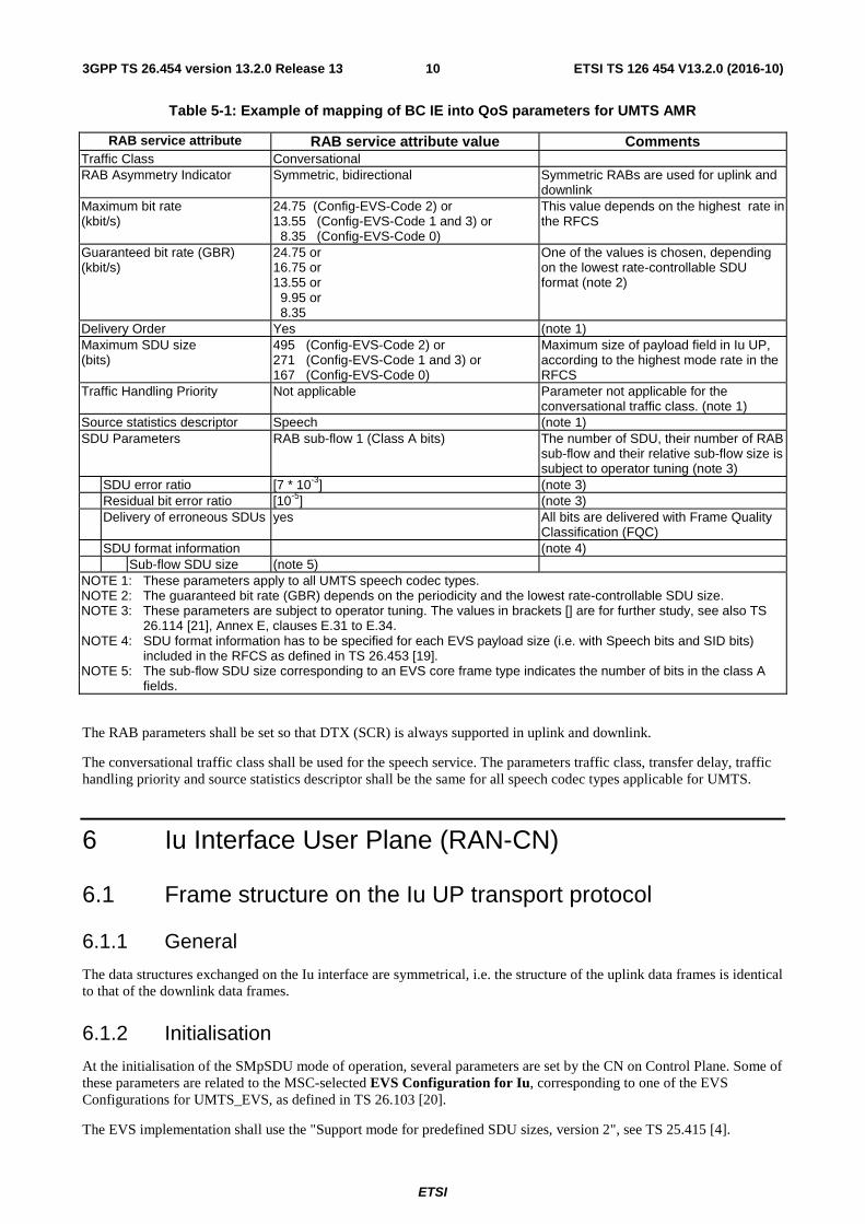
Table 5-1: Example of mapping of BC IE into QoS parameters for UMTS AMR
RAB service attribute RAB service attribute value Comments Traffic Class Conversational RAB Asymmetry Indicator Symmetric, bidirectional Symmetric RABs are used for uplink and
downlink Maximum bit rate (kbit/s)
24.75 (Config-EVS-Code 2) or 13.55 (Config-EVS-Code 1 and 3) or 8.35 (Config-EVS-Code 0)
This value depends on the highest rate in the RFCS
Guaranteed bit rate (GBR) (kbit/s)
24.75 or 16.75 or 13.55 or 9.95 or 8.35
One of the values is chosen, depending on the lowest rate-controllable SDU format (note 2)
Delivery Order Yes (note 1) Maximum SDU size (bits)
495 (Config-EVS-Code 2) or 271 (Config-EVS-Code 1 and 3) or 167 (Config-EVS-Code 0)
Maximum size of payload field in Iu UP, according to the highest mode rate in the RFCS
Traffic Handling Priority Not applicable Parameter not applicable for the conversational traffic class. (note 1)
Source statistics descriptor Speech (note 1) SDU Parameters RAB sub-flow 1 (Class A bits)
The number of SDU, their number of RAB sub-flow and their relative sub-flow size is subject to operator tuning (note 3)
SDU error ratio [7 * 10-3] (note 3) Residual bit error ratio [10-5] (note 3) Delivery of erroneous SDUs yes All bits are delivered with Frame Quality
Classification (FQC) SDU format information (note 4) Sub-flow SDU size (note 5) NOTE 1: These parameters apply to all UMTS speech codec types. NOTE 2: The guaranteed bit rate (GBR) depends on the periodicity and the lowest rate-controllable SDU size. NOTE 3: These parameters are subject to operator tuning. The values in brackets [] are for further study, see also TS
26.114 [21], Annex E, clauses E.31 to E.34. NOTE 4: SDU format information has to be specified for each EVS payload size (i.e. with Speech bits and SID bits)
included in the RFCS as defined in TS 26.453 [19]. NOTE 5: The sub-flow SDU size corresponding to an EVS core frame type indicates the number of bits in the class A
fields.
The RAB parameters shall be set so that DTX (SCR) is always supported in uplink and downlink.
The conversational traffic class shall be used for the speech service. The parameters traffic class, transfer delay, traffic handling priority and source statistics descriptor shall be the same for all speech codec types applicable for UMTS.
6 Iu Interface User Plane (RAN-CN)
6.1 Frame structure on the Iu UP transport protocol
6.1.1 General
The data structures exchanged on the Iu interface are symmetrical, i.e. the structure of the uplink data frames is identical to that of the downlink data frames.
6.1.2 Initialisation
At the initialisation of the SMpSDU mode of operation, several parameters are set by the CN on Control Plane. Some of these parameters are related to the MSC-selected EVS Configuration for Iu, corresponding to one of the EVS Configurations for UMTS_EVS, as defined in TS 26.103 [20].
The EVS implementation shall use the "Support mode for predefined SDU sizes, version 2", see TS 25.415 [4].
ETSI
ETSI TS 126 454 V13.2.0 (2016-10)113GPP TS 26.454 version 13.2.0 Release 13
The initialisation procedure for the Iu User Plane is described in TS 25.415 [4].
- RFCS (RAB sub-flow Combination Set): The RFCS on Iu corresponds to the EVS Configuration for Iu, as selected by the MSC. Each RFCS Index (RFCI) corresponds to one bit rate of the selected EVS Configuration for Iu. Note: The Traffic Format Combination Set (TFCS) on Uu, selected by the RNC, may belong to a smaller EVS Configuration. Example: Instead of EVS (Set 2), the RNC may select EVS (Set 1) or even EVS (Set 0). The UE determines the EVS Configuration for UE based on the selected TFCS, see also clause 7. The RFCS on Iu in uplink is the same as the RFCS on Iu in downlink. The actual RFCI used in downlink in a speech frame may, however, be different to the RFCI used in uplink for another speech frame.
- SCR (Source Controlled Rate), also known as DTX (Discontinuous Transmission), shall be supported in uplink and downlink.
- Delivery of erroneous SDUs: This parameter shall be set to YES. Erroneous or lost frames may be used to assist the error concealment procedures. PDU Type 0, containing a Payload CRC, shall be used for the transport of EVS data on Iu.
6.1.3 Time Alignment Procedure
The Transcoder in the Iu-terminating MGW, if present, should adjust the timing of the speech data transmission in downlink direction according to the time alignment frames sent by the RNC in Iu PDU Type 14 messages, see TS 25.415 [4]. The Time alignment procedure shall be dismissed in case of TrFO.
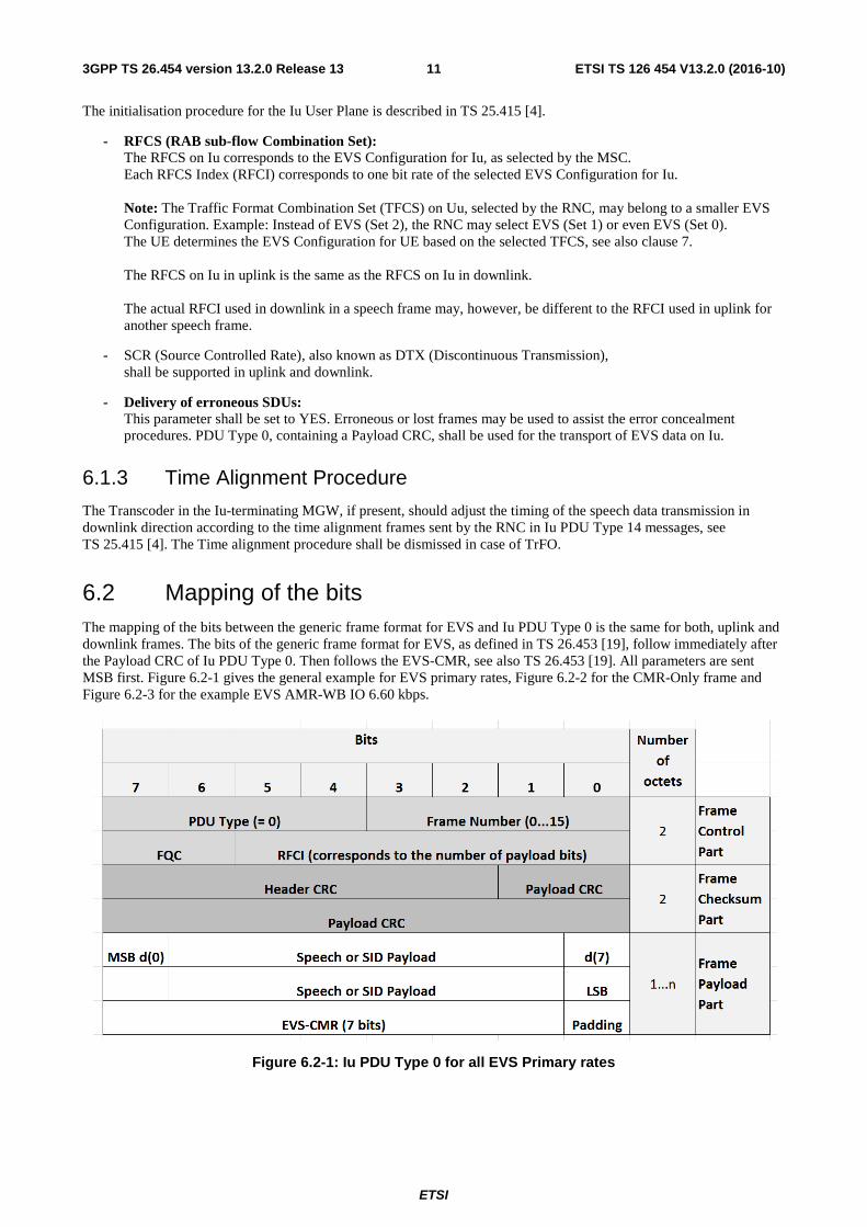
6.2 Mapping of the bits The mapping of the bits between the generic frame format for EVS and Iu PDU Type 0 is the same for both, uplink and downlink frames. The bits of the generic frame format for EVS, as defined in TS 26.453 [19], follow immediately after the Payload CRC of Iu PDU Type 0. Then follows the EVS-CMR, see also TS 26.453 [19]. All parameters are sent MSB first. Figure 6.2-1 gives the general example for EVS primary rates, Figure 6.2-2 for the CMR-Only frame and Figure 6.2-3 for the example EVS AMR-WB IO 6.60 kbps.
Figure 6.2-1: Iu PDU Type 0 for all EVS Primary rates
ETSI
ETSI TS 126 454 V13.2.0 (2016-10)123GPP TS 26.454 version 13.2.0 Release 13
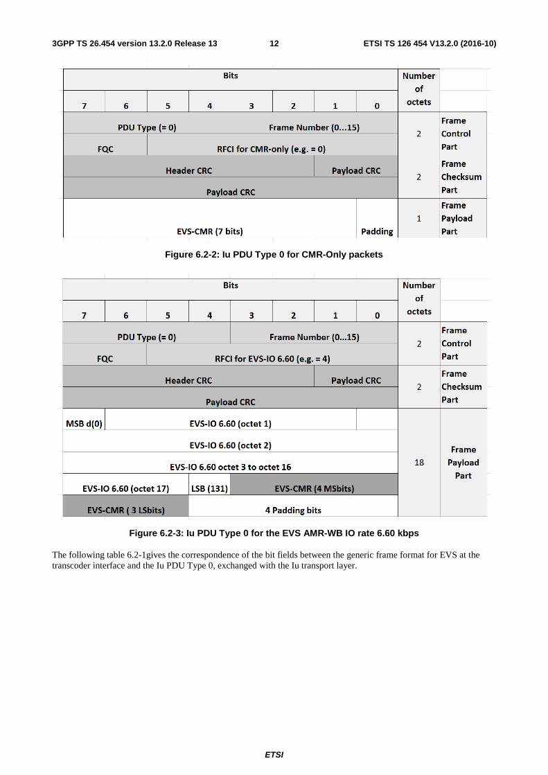
Figure 6.2-2: Iu PDU Type 0 for CMR-Only packets
Figure 6.2-3: Iu PDU Type 0 for the EVS AMR-WB IO rate 6.60 kbps
The following table 6.2-1gives the correspondence of the bit fields between the generic frame format for EVS at the transcoder interface and the Iu PDU Type 0, exchanged with the Iu transport layer.
ETSI
ETSI TS 126 454 V13.2.0 (2016-10)133GPP TS 26.454 version 13.2.0 Release 13
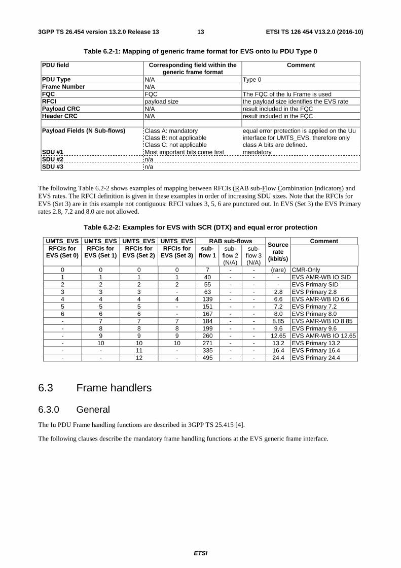
Table 6.2-1: Mapping of generic frame format for EVS onto Iu PDU Type 0
PDU field Corresponding field within the generic frame format
Comment
PDU Type N/A Type 0 Frame Number N/A FQC FQC The FQC of the Iu Frame is used RFCI payload size the payload size identifies the EVS rate Payload CRC N/A result included in the FQC Header CRC N/A result included in the FQC Payload Fields (N Sub-flows) Class A: mandatory
Class B: not applicable Class C: not applicable
equal error protection is applied on the Uu interface for UMTS_EVS, therefore only class A bits are defined.
SDU #1 Most important bits come first mandatory SDU #2 n/a SDU #3 n/a
The following Table 6.2-2 shows examples of mapping between RFCIs (RAB sub-Flow Combination Indicators) and EVS rates. The RFCI definition is given in these examples in order of increasing SDU sizes. Note that the RFCIs for EVS (Set 3) are in this example not contiguous: RFCI values 3, 5, 6 are punctured out. In EVS (Set 3) the EVS Primary rates 2.8, 7.2 and 8.0 are not allowed.
Table 6.2-2: Examples for EVS with SCR (DTX) and equal error protection
UMTS_EVS UMTS_EVS UMTS_EVS UMTS_EVS RAB sub-flows Source
rate (kbit/s)
Comment RFCIs for
EVS (Set 0) RFCIs for
EVS (Set 1) RFCIs for
EVS (Set 2) RFCIs for
EVS (Set 3) sub-
flow 1
sub- flow 2 (N/A)
sub- flow 3 (N/A)
0 0 0 0 7 - - (rare) CMR-Only 1 1 1 1 40 - - - EVS AMR-WB IO SID 2 2 2 2 55 - - - EVS Primary SID 3 3 3 - 63 - - 2.8 EVS Primary 2.8 4 4 4 4 139 - - 6.6 EVS AMR-WB IO 6.6 5 5 5 - 151 - - 7.2 EVS Primary 7.2 6 6 6 - 167 - - 8.0 EVS Primary 8.0 - 7 7 7 184 - - 8.85 EVS AMR-WB IO 8.85 - 8 8 8 199 - - 9.6 EVS Primary 9.6 - 9 9 9 260 - - 12.65 EVS AMR-WB IO 12.65 - 10 10 10 271 - - 13.2 EVS Primary 13.2 - - 11 - 335 - - 16.4 EVS Primary 16.4 - - 12 - 495 - - 24.4 EVS Primary 24.4
6.3 Frame handlers
6.3.0 General
The Iu PDU Frame handling functions are described in 3GPP TS 25.415 [4].
The following clauses describe the mandatory frame handling functions at the EVS generic frame interface.
ETSI
ETSI TS 126 454 V13.2.0 (2016-10)143GPP TS 26.454 version 13.2.0 Release 13
6.3.1 Handling of frames from TC to Iu interface (downlink)
6.3.1.0 General
The frames from the EVS Transcoder (TC) in generic EVS frame format are mapped onto the Iu PDU Type 0 as follows.
6.3.1.1 Frame Quality Classification
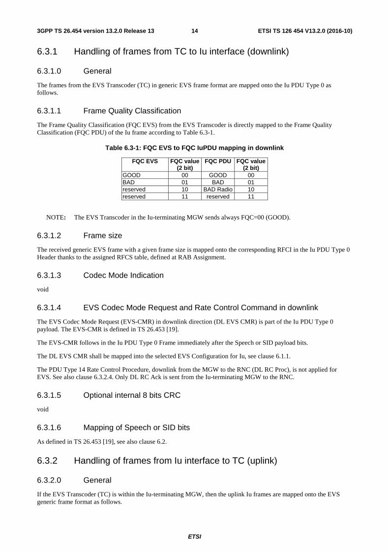
The Frame Quality Classification (FQC EVS) from the EVS Transcoder is directly mapped to the Frame Quality Classification (FQC PDU) of the Iu frame according to Table 6.3-1.
Table 6.3-1: FQC EVS to FQC IuPDU mapping in downlink
FQC EVS FQC value (2 bit)
FQC PDU FQC value (2 bit)
GOOD 00 GOOD 00 BAD 01 BAD 01 reserved 10 BAD Radio 10 reserved 11 reserved 11
NOTE: The EVS Transcoder in the Iu-terminating MGW sends always FQC=00 (GOOD).
6.3.1.2 Frame size
The received generic EVS frame with a given frame size is mapped onto the corresponding RFCI in the Iu PDU Type 0 Header thanks to the assigned RFCS table, defined at RAB Assignment.
6.3.1.3 Codec Mode Indication
void
6.3.1.4 EVS Codec Mode Request and Rate Control Command in downlink
The EVS Codec Mode Request (EVS-CMR) in downlink direction (DL EVS CMR) is part of the Iu PDU Type 0 payload. The EVS-CMR is defined in TS 26.453 [19].
The EVS-CMR follows in the Iu PDU Type 0 Frame immediately after the Speech or SID payload bits.
The DL EVS CMR shall be mapped into the selected EVS Configuration for Iu, see clause 6.1.1.
The PDU Type 14 Rate Control Procedure, downlink from the MGW to the RNC (DL RC Proc), is not applied for EVS. See also clause 6.3.2.4. Only DL RC Ack is sent from the Iu-terminating MGW to the RNC.
6.3.1.5 Optional internal 8 bits CRC
void
6.3.1.6 Mapping of Speech or SID bits
As defined in TS 26.453 [19], see also clause 6.2.
6.3.2 Handling of frames from Iu interface to TC (uplink)
6.3.2.0 General
If the EVS Transcoder (TC) is within the Iu-terminating MGW, then the uplink Iu frames are mapped onto the EVS generic frame format as follows.
ETSI
ETSI TS 126 454 V13.2.0 (2016-10)153GPP TS 26.454 version 13.2.0 Release 13
6.3.2.1 Frame Quality Classification
At reception of UL Iu PDU Type 0 the Iu frame handler function set the EVS Frame Quality Classification (EVS FQC) according to the received PDU FQC, the Header-CRC check, and the Payload-CRC check (see 25.415 [4]). The EVS payload size (EVS bit rate) and EVS Frame Quality Classification are determined according to the following table, if the Header-CRC and the Payload-CRC indicate a correctly received PDU:
Table 6.3-2: PDU FQC to EVS FQC and EVS payload size mapping
PDU FQC PDU FQC value (2 bits)
EVS FQC value (2 bits)
EVS FQC resulting payload size
GOOD 00 00 GOOD from RFCI BAD 01 01 BAD from RFCI
BAD Radio 10 10 BAD Radio from RFCI Reserved 11 11 Reserved Reserved
NOTE: A Speech or SID Frame received on Iu with FQC "BAD Radio" is an indication that the UE is still
sending and at least the payload is partly received, i.e. the connection is not lost. In case of BAD SID frames Comfort Noise Generation is continued, based on the previous SID parameter set.
6.3.2.2 Frame Type
void
6.3.2.3 Codec Mode Indication
void
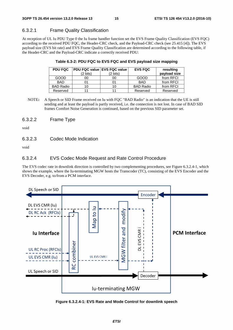
6.3.2.4 EVS Codec Mode Request and Rate Control Procedure
The EVS codec rate in downlink direction is controlled by two complementing procedures, see Figure 6.3.2.4-1, which shows the example, where the Iu-terminating MGW hosts the Transcoder (TC), consisting of the EVS Encoder and the EVS Decoder, e.g. to/from a PCM interface.
Figure 6.3.2.4-1: EVS Rate and Mode Control for downlink speech
ETSI
ETSI TS 126 454 V13.2.0 (2016-10)163GPP TS 26.454 version 13.2.0 Release 13
Each UL PDU Type 0, received by the MGW via the Iu-Interface in uplink, contains the UL EVS CMR (Iu), as sent by the UE in uplink.
UL PDU Type 14, received by the MGW via the Iu-Interface in uplink, may contain an UL RC Proc, specifying the maximum bit rate the RNC allows in downlink for all subsequent speech frames. This UL RC Proc contains all initialized RFCIs. The RFCIs with bit rates exceeding the maximum bit rate allowed in downlink are banned by the RNC by setting their RFCI flags to value 1, see TS 25.415 [4].
The DL RC Ack, to be sent in downlink, shall contain all initialized RFCIs. The RFCIs with bit rates exceeding the maximum bit rate allowed by the DL EVS CMR (Iu) shall be banned by setting their RFCI flags to value 1, see TS 25.415 [4].
The Iu-terminating MGW shall combine both, UL EVS CMR (Iu) and the maximum rate, as allowed by the UL RC Proc (see the RC combiner in Figure 6.3.2.4-1) and shall restrict the received UL EVS CMR (Iu) to the maximum rate the RNC allows for downlink, resulting in UL EVS CMR i ("i" like "internal").
If necessary, the RC combiner modifies the audio bandwidth contained in the UL EVS CMR (Iu) to the next smaller audio bandwidth that fulfils the maximum rate requirement set by the RNC for downlink with UL RC Proc or UL Iu_Init.
NOTE: The RNC parameters, also the RNC max rate in DL, are subject to operator policy.
The major operation mode contained in the UL EVS CMR (Iu) shall, however, not be modified by this RC combiner. If necessary, the RC combiner selects the next lower rate that corresponds to the received major operation mode.
In addition, subject to operator policy, the MGW may filter and modify the resulting UL EVS CMR i further. The MGW shall remember the resulting UL EVS CMR i, until it is modified again, see also clause 11.
In each new frame that is sent to the local EVS Encoder, if present, the remembered UL EVS CMR i is resent, in order to control the EVS Encoder-mode for the downlink direction.
The EVS Decoder within the Iu-terminating MGW, if present, shall accept and decode every (good) Speech and SID frame received in uplink direction. This decoder generates in addition the DL EVS CMR i, defining the maximum EVS mode this decoder wants to receive in uplink. Typically this "DL EVS CMR i" is identical with the highest EVS mode of the EVS Configuration for Iu. The decoder may reduce it to a lower mode, e.g. if the UL Speech frames have a high frame loss rate.
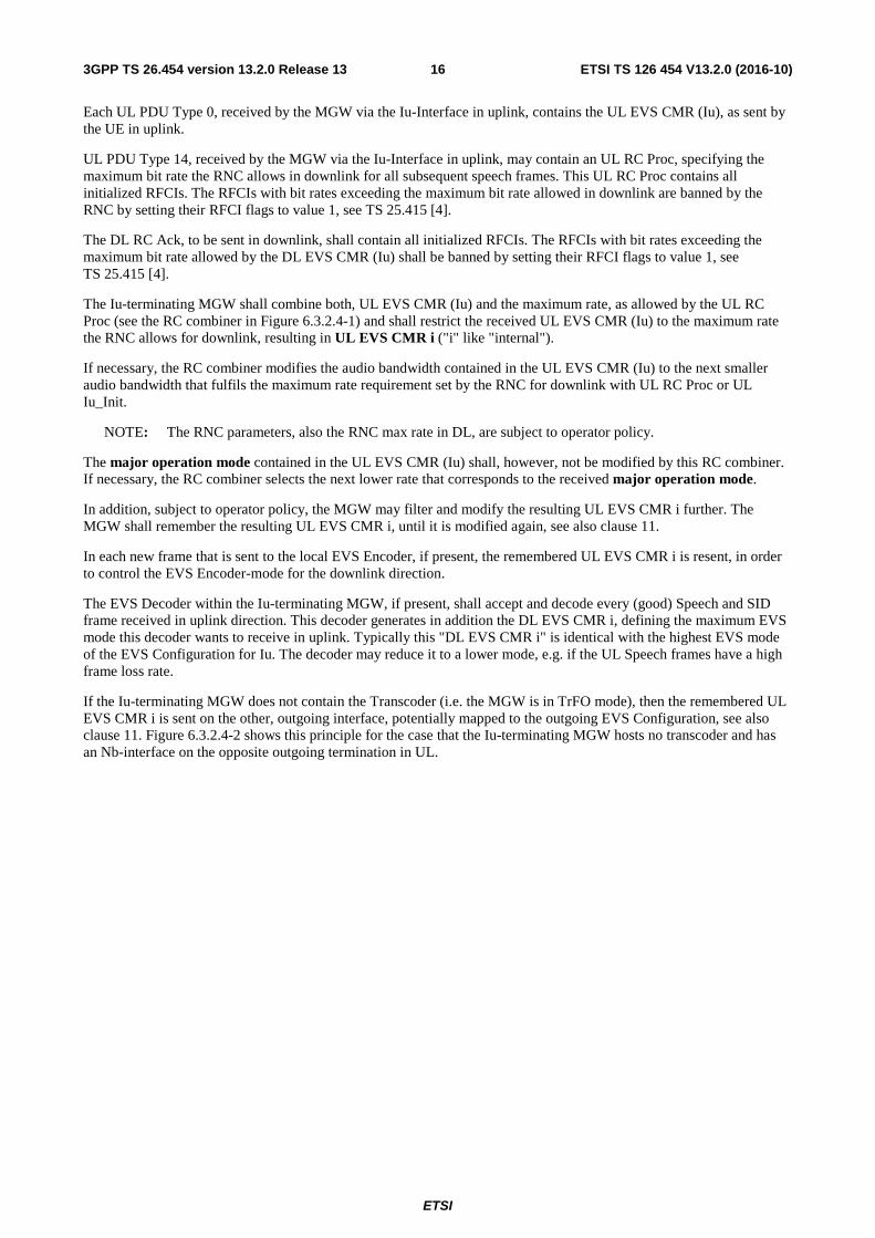
If the Iu-terminating MGW does not contain the Transcoder (i.e. the MGW is in TrFO mode), then the remembered UL EVS CMR i is sent on the other, outgoing interface, potentially mapped to the outgoing EVS Configuration, see also clause 11. Figure 6.3.2.4-2 shows this principle for the case that the Iu-terminating MGW hosts no transcoder and has an Nb-interface on the opposite outgoing termination in UL.
ETSI
ETSI TS 126 454 V13.2.0 (2016-10)173GPP TS 26.454 version 13.2.0 Release 13
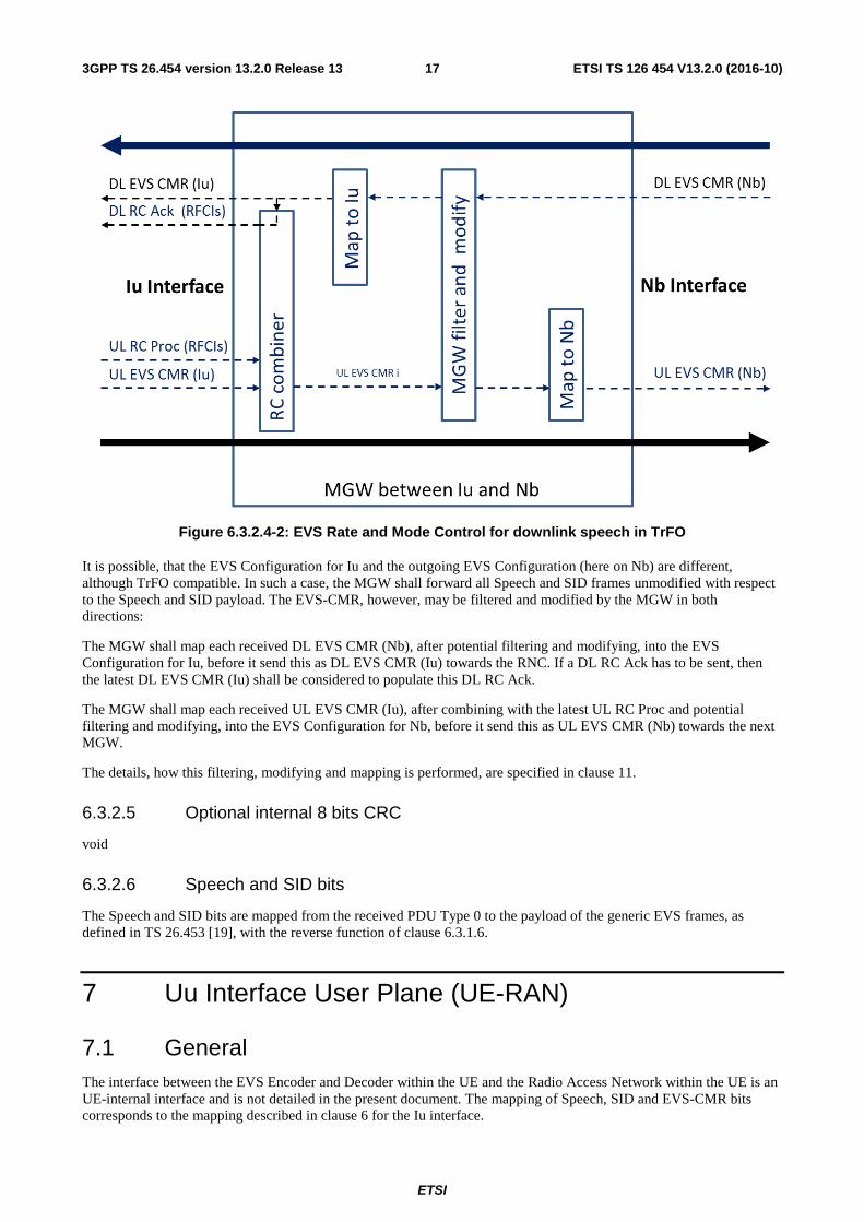
Figure 6.3.2.4-2: EVS Rate and Mode Control for downlink speech in TrFO
It is possible, that the EVS Configuration for Iu and the outgoing EVS Configuration (here on Nb) are different, although TrFO compatible. In such a case, the MGW shall forward all Speech and SID frames unmodified with respect to the Speech and SID payload. The EVS-CMR, however, may be filtered and modified by the MGW in both directions:
The MGW shall map each received DL EVS CMR (Nb), after potential filtering and modifying, into the EVS Configuration for Iu, before it send this as DL EVS CMR (Iu) towards the RNC. If a DL RC Ack has to be sent, then the latest DL EVS CMR (Iu) shall be considered to populate this DL RC Ack.
The MGW shall map each received UL EVS CMR (Iu), after combining with the latest UL RC Proc and potential filtering and modifying, into the EVS Configuration for Nb, before it send this as UL EVS CMR (Nb) towards the next MGW.
The details, how this filtering, modifying and mapping is performed, are specified in clause 11.
6.3.2.5 Optional internal 8 bits CRC
void
6.3.2.6 Speech and SID bits
The Speech and SID bits are mapped from the received PDU Type 0 to the payload of the generic EVS frames, as defined in TS 26.453 [19], with the reverse function of clause 6.3.1.6.
7 Uu Interface User Plane (UE-RAN)
7.1 General The interface between the EVS Encoder and Decoder within the UE and the Radio Access Network within the UE is an UE-internal interface and is not detailed in the present document. The mapping of Speech, SID and EVS-CMR bits corresponds to the mapping described in clause 6 for the Iu interface.
ETSI
ETSI TS 126 454 V13.2.0 (2016-10)183GPP TS 26.454 version 13.2.0 Release 13
The UE shall decode every Speech or SID frame received in downlink direction, regardless of the EVS mode of operation in uplink.
The UE shall always apply in uplink the "Source Controlled Operation" (SCR), also called "Discontinuous Transmission" (DTX).
If the UE uses the EVS AMR-WB IO mode of operation to encode speech for the uplink direction, then it shall restrict changes of the Codec Mode to every other frame (40 ms grid) and to neighbouring modes.
NOTE: In case of modification of the maximum rate (e.g. by the RNC), it takes a short time period until the speech frames sent by the UE to the Radio Access Network comply with the modified maximum rate. To facilitate optimization of performance (for instance avoiding problems like audio gaps due to discarded packets) in sending direction from the UE to the network when changing mode as requested, it is a good implementation practice to allow adaptation of the UE Encoder to take effect, and to maintain currently used rate for the next few frames after the information about the rate adaptation has been sent to the UE Encoder.
ETSI
ETSI TS 126 454 V13.2.0 (2016-10)193GPP TS 26.454 version 13.2.0 Release 13
7.2 Determination of the local EVS encoding mode
Table 7.2-1: Local EVS encoding mode and Interworking
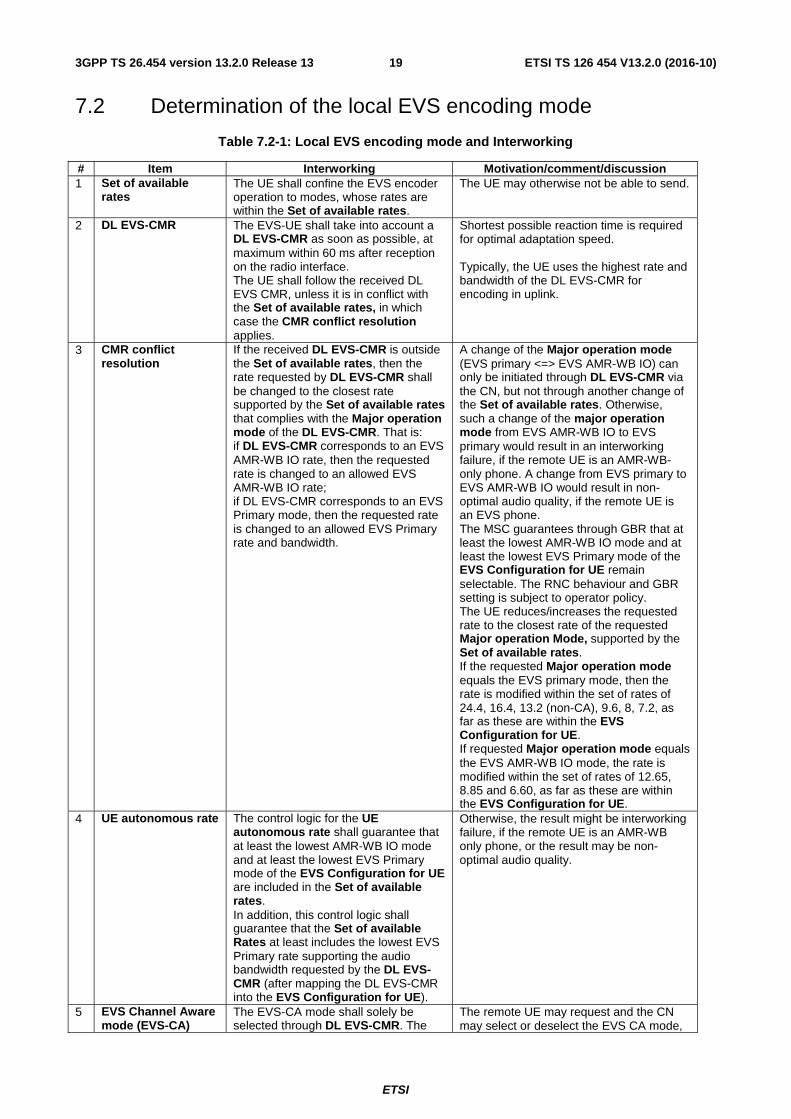
# Item Interworking Motivation/comment/discussion 1 Set of available
rates The UE shall confine the EVS encoder operation to modes, whose rates are within the Set of available rates.
The UE may otherwise not be able to send.
2 DL EVS-CMR The EVS-UE shall take into account a DL EVS-CMR as soon as possible, at maximum within 60 ms after reception on the radio interface. The UE shall follow the received DL EVS CMR, unless it is in conflict with the Set of available rates, in which case the CMR conflict resolution applies.
Shortest possible reaction time is required for optimal adaptation speed. Typically, the UE uses the highest rate and bandwidth of the DL EVS-CMR for encoding in uplink.
3 CMR conflict resolution
If the received DL EVS-CMR is outside the Set of available rates, then the rate requested by DL EVS-CMR shall be changed to the closest rate supported by the Set of available rates that complies with the Major operation mode of the DL EVS-CMR. That is: if DL EVS-CMR corresponds to an EVS AMR-WB IO rate, then the requested rate is changed to an allowed EVS AMR-WB IO rate; if DL EVS-CMR corresponds to an EVS Primary mode, then the requested rate is changed to an allowed EVS Primary rate and bandwidth.
A change of the Major operation mode (EVS primary <=> EVS AMR-WB IO) can only be initiated through DL EVS-CMR via the CN, but not through another change of the Set of available rates. Otherwise, such a change of the major operation mode from EVS AMR-WB IO to EVS primary would result in an interworking failure, if the remote UE is an AMR-WB-only phone. A change from EVS primary to EVS AMR-WB IO would result in non-optimal audio quality, if the remote UE is an EVS phone. The MSC guarantees through GBR that at least the lowest AMR-WB IO mode and at least the lowest EVS Primary mode of the EVS Configuration for UE remain selectable. The RNC behaviour and GBR setting is subject to operator policy. The UE reduces/increases the requested rate to the closest rate of the requested Major operation Mode, supported by the Set of available rates. If the requested Major operation mode equals the EVS primary mode, then the rate is modified within the set of rates of 24.4, 16.4, 13.2 (non-CA), 9.6, 8, 7.2, as far as these are within the EVS Configuration for UE. If requested Major operation mode equals the EVS AMR-WB IO mode, the rate is modified within the set of rates of 12.65, 8.85 and 6.60, as far as these are within the EVS Configuration for UE.
4 UE autonomous rate The control logic for the UE autonomous rate shall guarantee that at least the lowest AMR-WB IO mode and at least the lowest EVS Primary mode of the EVS Configuration for UE are included in the Set of available rates. In addition, this control logic shall guarantee that the Set of available Rates at least includes the lowest EVS Primary rate supporting the audio bandwidth requested by the DL EVS-CMR (after mapping the DL EVS-CMR into the EVS Configuration for UE).
Otherwise, the result might be interworking failure, if the remote UE is an AMR-WB only phone, or the result may be non-optimal audio quality.
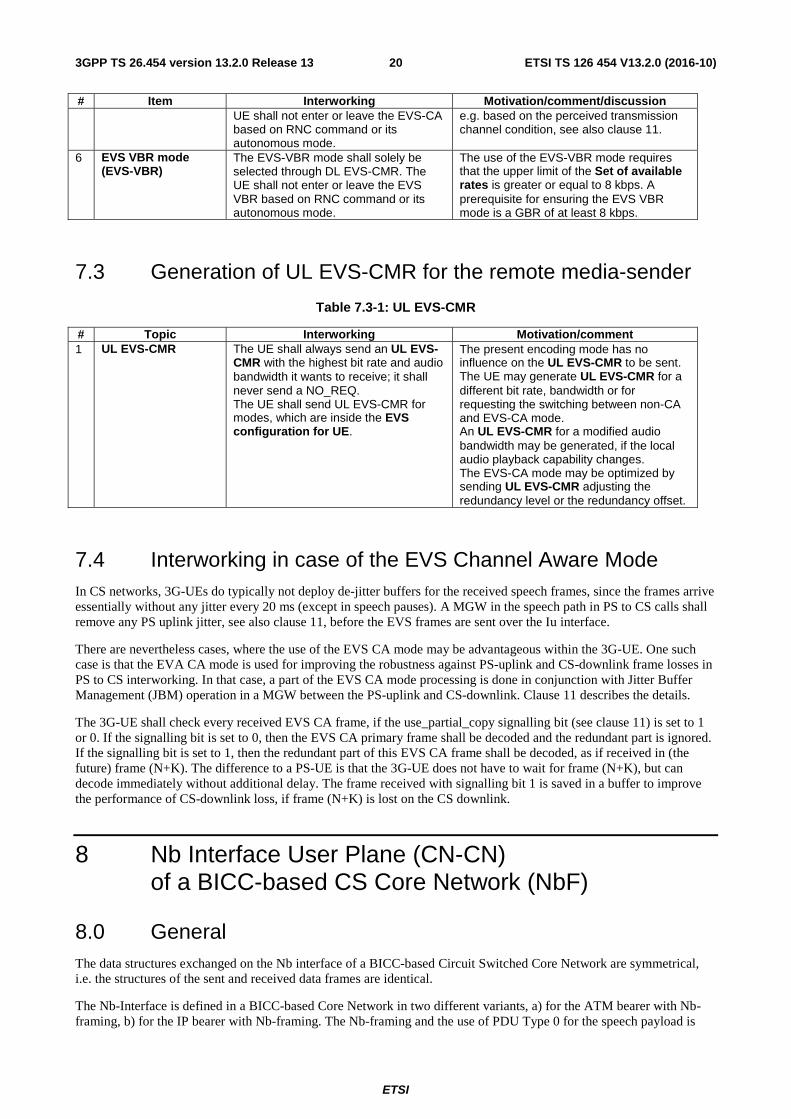
5 EVS Channel Aware mode (EVS-CA)
The EVS-CA mode shall solely be selected through DL EVS-CMR. The
The remote UE may request and the CN may select or deselect the EVS CA mode,
ETSI
ETSI TS 126 454 V13.2.0 (2016-10)203GPP TS 26.454 version 13.2.0 Release 13
# Item Interworking Motivation/comment/discussion UE shall not enter or leave the EVS-CA based on RNC command or its autonomous mode.
e.g. based on the perceived transmission channel condition, see also clause 11.
6 EVS VBR mode (EVS-VBR)
The EVS-VBR mode shall solely be selected through DL EVS-CMR. The UE shall not enter or leave the EVS VBR based on RNC command or its autonomous mode.
The use of the EVS-VBR mode requires that the upper limit of the Set of available rates is greater or equal to 8 kbps. A prerequisite for ensuring the EVS VBR mode is a GBR of at least 8 kbps.
7.3 Generation of UL EVS-CMR for the remote media-sender
Table 7.3-1: UL EVS-CMR
# Topic Interworking Motivation/comment 1 UL EVS-CMR The UE shall always send an UL EVS-
CMR with the highest bit rate and audio bandwidth it wants to receive; it shall never send a NO_REQ. The UE shall send UL EVS-CMR for modes, which are inside the EVS configuration for UE.
The present encoding mode has no influence on the UL EVS-CMR to be sent. The UE may generate UL EVS-CMR for a different bit rate, bandwidth or for requesting the switching between non-CA and EVS-CA mode. An UL EVS-CMR for a modified audio bandwidth may be generated, if the local audio playback capability changes. The EVS-CA mode may be optimized by sending UL EVS-CMR adjusting the redundancy level or the redundancy offset.
7.4 Interworking in case of the EVS Channel Aware Mode In CS networks, 3G-UEs do typically not deploy de-jitter buffers for the received speech frames, since the frames arrive essentially without any jitter every 20 ms (except in speech pauses). A MGW in the speech path in PS to CS calls shall remove any PS uplink jitter, see also clause 11, before the EVS frames are sent over the Iu interface.
There are nevertheless cases, where the use of the EVS CA mode may be advantageous within the 3G-UE. One such case is that the EVA CA mode is used for improving the robustness against PS-uplink and CS-downlink frame losses in PS to CS interworking. In that case, a part of the EVS CA mode processing is done in conjunction with Jitter Buffer Management (JBM) operation in a MGW between the PS-uplink and CS-downlink. Clause 11 describes the details.
The 3G-UE shall check every received EVS CA frame, if the use_partial_copy signalling bit (see clause 11) is set to 1 or 0. If the signalling bit is set to 0, then the EVS CA primary frame shall be decoded and the redundant part is ignored. If the signalling bit is set to 1, then the redundant part of this EVS CA frame shall be decoded, as if received in (the future) frame (N+K). The difference to a PS-UE is that the 3G-UE does not have to wait for frame (N+K), but can decode immediately without additional delay. The frame received with signalling bit 1 is saved in a buffer to improve the performance of CS-downlink loss, if frame (N+K) is lost on the CS downlink.
8 Nb Interface User Plane (CN-CN) of a BICC-based CS Core Network (NbF)
8.0 General The data structures exchanged on the Nb interface of a BICC-based Circuit Switched Core Network are symmetrical, i.e. the structures of the sent and received data frames are identical.
The Nb-Interface is defined in a BICC-based Core Network in two different variants, a) for the ATM bearer with Nb-framing, b) for the IP bearer with Nb-framing. The Nb-framing and the use of PDU Type 0 for the speech payload is
ETSI
ETSI TS 126 454 V13.2.0 (2016-10)213GPP TS 26.454 version 13.2.0 Release 13
common for both versions of the Nb-Interface.
These two versions also share the principle of "Nb_Init" by PDU Type 14 messages, where the Nb-Interface is initialized on User Plane level.
8.1 Frame structure on the Nb UP transport protocol
8.1.0 General
Delivery of erroneous SDUs for EVS-coded speech on the Nb-Interface shall be set to: "YES" in a BICC-based Circuit Switched Core Network. Erroneous speech frames may be used to assist the error concealment procedures.
Therefore, PDU Type 0 (with payload CRC) shall be used for the transport of EVS-coded speech on the Nb interface.
8.1.1 Initialisation
The initialisation procedure is used for support mode. At the initialisation, several parameters are set by the CN. The initialisation procedure for the Nb Interface is described in TS 29.414 [6].
The EVS implementation shall use the "Support mode for predefined SDU sizes, version 2", see TS 25.415 [4].
8.1.2 Time Alignment Procedure
The handling of Time Alignment on the Nb Interface is described in TS 29.414 [6]. The Time alignment procedure shall be dismissed in case of TrFO.
8.1.3 SID Frame Generation
The generation of SID frames is determined by the EVS Speech Encoder. The radio subsystem does not influence this timing.
8.1.4 Rate and Mode Control and CMR-Only frames
For EVS the PDU Type 14 is not used on the Nb interface for Rate Control. Instead, every PDU Type 0 on the Nb interface (with Speech, SID or CMR-Only content) contains the active EVS-CMR. CMR-code-point NO_REQ shall not be used.
The UE or any node in the speech path (e.g. a MGW during handover) may send CMR-Only frames during speech pauses, if an urgent EVS Codec Mode Request has to be sent.
8.2 Mapping of the EVS bits
8.2.1 Mapping for EVS Speech and SID frames
The mapping of the bits between the generic EVS frames and the PDU Type 0 for the Nb Interface is identical to the mapping on the Iu Interface for PDU Type 0.
8.2.2 Mapping for EVS-CMR
The mapping of the EVS-CMR to the PDU Type 0 for the Nb Interface is identical to the mapping on the Iu Interface.
8.3 Frame handlers Nb PDU Frame handling functions are described in TS 29.414 [6].
ETSI
ETSI TS 126 454 V13.2.0 (2016-10)223GPP TS 26.454 version 13.2.0 Release 13
9 Nb Interface User Plane (CN-CN) of a SIP-I-based CS Core Network (NboIP)
9.1 General The SIP-I-based Circuit Switched Core Network is specified in 3GPP TS 23.231 [3]. The User Plane in this Core Network is further specified in 3GPP TS 29.414 [6]. RTP is specified in IETF RFC 3550 [8].
RTP is used in a SIP-I-based Circuit Switched Core Network as framing protocol at the Nb-Interface (without Nb-framing protocol). The rules for the usage of RTP and RTCP in 3GPP TS 29.414 [6] are applicable in combination with further Codec-specific rules provided in the present specification.
9.2 Frame Structure
9.2.0 General
The RTP framing for EVS is specified in TS 26.445 [12]. For details on the SIP-I-based Nb interface, see clause 9.3.
9.2.1 Initialisation
At the Nb-Interface in a SIP-I-based Core Network, direct RTP packing without Nb-framing is applied. Therefore, the use of PDU Type 0 for the speech payload and PDU Type 14 for Rate Control is not applicable. In addition, the principle of "Nb_Init" is not applicable for a SIP-I-based Core Network.
9.2.2 Time Alignment Procedure
Time Alignment is not specified in a SIP-I-based Circuit Switched Core Network.
9.2.3 SID Frame Generation
The generation of SID frames is determined by the EVS Speech Encoder. The radio subsystem does not influence this timing.
9.2.4 Rate and Mode Control and CMR-Only frames
Every RTP packet on the Nb interface (with Speech, SID or CMR-Only content) contains the active EVS-CMR.
The UE or any node in the speech path (e.g. a MGW during handover) may send CMR-Only frames during speech pauses, if an urgent EVS Codec Mode Request has to be sent.
9.3 RTP Packing for EVS on Nb for SIP-I The RTP packing for EVS on this version of the Nb-Interface is as specified in TS 26.445[12], with the following additional constraints:
The RTP Payload Type number for EVS for the Nb-Interface is determined by the MSC-S dynamically.
The headerful format shall be used on Nb for SIP-I.
Each RTP packet on Nb shall contain exactly either one Speech or one SID or one CMR-Only frame. RTP redundancy is not applied on Nb.
Every RTP packet on Nb shall contain the active EVS-CMR. CMR-code-point NO_REQ shall not be used.
The active EVS-CMR shall comply with the negotiated EVS Configuration for Nb.
ETSI
ETSI TS 126 454 V13.2.0 (2016-10)233GPP TS 26.454 version 13.2.0 Release 13
RTCP-APP is not used on the SIP-I based Nb interface.
10 Mb Interface User Plane
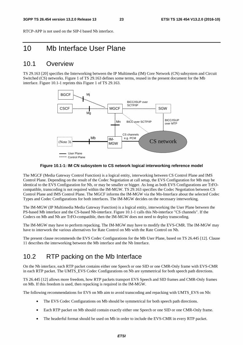
10.1 Overview TS 29.163 [20] specifies the Interworking between the IP Multimedia (IM) Core Network (CN) subsystem and Circuit Switched (CS) networks. Figure 1 of TS 29.163 defines some terms, reused in the present document for the Mb interface. Figure 10.1-1 reprints this Figure 1 of TS 29.163.
(Note 3)
CSCF
CS network IM- MGW
MGCF SGW
Mb CS channels e.g. PCM
BICC/ISUP over MTP
Mn
User Plane Control Plane
BICC/ISUP over SCTP/IP
Mg
BGCF Mj
BICC over SCTP/IP
Figure 10.1-1: IM CN subsystem to CS network logical interworking reference model
The MGCF (Media Gateway Control Function) is a logical entity, interworking between CS Control Plane and IMS Control Plane. Depending on the result of the Codec Negotiation at call setup, the EVS Configuration for Mb may be identical to the EVS Configuration for Nb, or may be smaller or bigger. As long as both EVS Configurations are TrFO-compatible, transcoding is not required within the IM-MGW. TS 29.163 specifies the Codec Negotiation between CS Control Plane and IMS Control Plane. The MGCF informs the IM-MGW via the Mn-Interface about the selected Codec Types and Codec Configurations for both interfaces. The IM-MGW decides on the necessary interworking.
The IM-MGW (IP Multimedia Media Gateway Function) is a logical entity, interworking the User Plane between the PS-based Mb interface and the CS-based Nb-interface. Figure 10.1-1 calls this Nb-interface "CS channels". If the Codecs on Mb and Nb are TrFO-compatible, then the IM-MGW does not need to deploy transcoding.
The IM-MGW may have to perform repacking. The IM-MGW may have to modify the EVS-CMR. The IM-MGW may have to interwork the various alternatives for Rate Control on Mb with the Rate Control on Nb.
The present clause recommends the EVS Codec Configurations for the Mb User Plane, based on TS 26.445 [12]. Clause 11 describes the interworking between the Mb interface and the Nb Interface.
10.2 RTP packing on the Mb Interface On the Nb interface, each RTP packet contains either one Speech or one SID or one CMR-Only frame with EVS-CMR in each RTP packet. The UMTS_EVS Codec Configurations on Nb are symmetrical for both speech path directions.
TS 26.445 [12] allows more freedom, how RTP packets transport EVS Speech and SID frames and CMR-Only frames on Mb. If this freedom is used, then repacking is required in the IM-MGW.
The following recommendations for EVS on Mb aim to avoid transcoding and repacking with UMTS_EVS on Nb:
• The EVS Codec Configurations on Mb should be symmetrical for both speech path directions.
• Each RTP packet on Mb should contain exactly either one Speech or one SID or one CMR-Only frame.
• The headerful format should be used on Mb in order to include the EVS-CMR in every RTP packet.
ETSI
ETSI TS 126 454 V13.2.0 (2016-10)243GPP TS 26.454 version 13.2.0 Release 13
• Every RTP packet on Mb should contain the active EVS-CMR, never NO_REQ (0x7Fh, see TS 26.445).
• DTX should be allowed on the Mb interface in both directions.
10.3 Rate and mode control for EVS on Mb On the Nb-interface the EVS-CMR provides rate and mode control for UMTS_EVS and for interworking between EVS and AMR-WB. TS 26.453 [19] specifies EVS-CMR in accordance with TS 26.445 [12] in sub-clause A.2.2.1.1. On Nb the EVS-CMR is always transported in every Speech, SID and some rare CMR-Only frames. EVS-CMR is not acknowledged, because this permanent, redundant transmission is a reliable Forward Error Correction.
TS 26.445 specifies four different alternatives how to transport CMR on the Mb interface, depending on the SDP Offer/Answer negotiation.
Mb-alt 1: The EVS-CMR is transported in RTP on Mb in every Speech, SID and some rare CMR-Only frames.
Mb-alt 2: The EVS-CMR may be transported in RTP packets on Mb "on demand", i.e. only when the EVS-CMR value changes.
Mb-alt 3: The EVS-CMR is forbidden in RTP on Mb and instead EVS-CMR is transported in RTCP-APP on demand on Mb. RTCP-APP is not deployed on the Nb interface.
Mb-alt 4: The EVS-CMR is forbidden in RTP and RTCP on Mb. Consequently, Transcoding is required in the IM-MGW.
Mb-alt 1 is the preferred and recommended alternative for interworking with UMTS_EVS on Nb.
Clause 11 describes the interworking between these alternatives on Mb and the transport of EVS-CMR on Nb.
11 Interworking between MGW Terminations
11.1 Interworking between different EVS Configurations
11.1.0 General
It may happen, e.g. to combat cell overload, that the RNC selects a smaller EVS Configuration for Uu, than the EVS Configuration for Iu, which the MSC has selected, see also clause 7.
Example: The local MSC selects during the Codec Negotiation with the remote side the EVS Configuration EVS (Set 2), which is equivalent to the SDP description EVS (br=5.9-24.4, bw=nb-fb). The RAB Assignment Request towards the local RNC contains the corresponding rates, see Table 6.2-2. The RNC, however, decides to setup a set of TFCs on the Uu interface that is corresponding to EVS (Set 1), equivalent to the SDP description EVS (br=5.9-13.2, bw=nb-swb). The UE determines the EVS Configuration for UE based on the set of TFCs. When the RNC select a smaller transport channel for Uu, then this is unknown to the MSC and MGW and to the UE. The RNC may also change the transport channel for Uu (and by that the EVS Configuration for UE) during the call without notice to the MSC or MGW. Only indirectly, when by UL Iu_Init and/or UL RC Proc the maximum rate in DL is set, the MGW gets some information on limitations of the Uu interface in DL, see clause 6.
In such a situation, the Iu-terminating MGW may send DL EVS-CMRs that are outside the EVS Configuration for UE. The UE maps these EVS-CMRs into its known EVS Configuration for UE, see clause 7. Example: The Iu-terminating MGW may send DL EVS-CMR (br=24.4; bw=fb) and the UE needs to map this to DL EVS-CMR (br=13.2; bw=swb).
A similar situation may happen within the IM-MGW between the CS-internal interface and the Mb interface: different EVS Configurations may be used. The EVS Configuration for Mb may be often bigger than inside the CS network.
Example: After SRVCC, the IMS Selected Codec (applied still on Mb) may be different, but TrFO-compatible to the Target RAN Codec (applied on the CS channel of the IM-MGW). The Target RAN Codec may be EVS (Set 3), equivalent to the SDP description EVS (br=9.6-13.2, bw=swb), while the IMS Selected Codec on Mb may be
ETSI
ETSI TS 126 454 V13.2.0 (2016-10)253GPP TS 26.454 version 13.2.0 Release 13
equivalent to EVS (br=9.6-24.4; bw=swb). The IMS-side may send CMR (br=24.4; bw=swb) and the IM-MGW maps this to EVS-CMR (br=13.2; bw=swb).
The same situation may happen between CS-internal interfaces (Iu, Nb, A): different EVS Configurations may be used on both sides of the MGW. These scenarios occur mainly after handover, but they are not excluded for call setup.
In all such cases the EVS-CMR, coming into one termination of the MGW (or IM-MGW) may have to be mapped into the EVS Configuration on the outgoing termination. Without this mapping, the receiver of an EVS-CMR may ignore the EVS-CMR, because it is outside its own EVS Configuration, see TS 26.445, clause A.2.2.1.1, CMR byte. The only (known) exception is the mapping onto the Iu Interface and the handling by the 3G-UE, because, as described above, the 3G-UE may get EVS-CMRs that fit to the EVS Configuration for Iu, but are outside the EVS Configuration for UE.
TS 26.103 [20] specifies three "EVS Bottom Up Configurations", EVS (Set 0), EVS (Set 1) and EVS (Set 2) and one "Single audio band Configuration", EVS (Set 3) for the 3G-CS network.
The Interworking rules are defined in the following clauses.
11.1.1 Interworking between EVS Bottom Up Configurations
If the EVS Configurations on both sides of the MGW are identical, then no mapping is necessary.
If the EVS Bottom up Configuration on one side (e.g. Set 2 on Nb or Mb), is bigger than the EVS Bottom up Configuration on the other side (e.g. Set 1 on Iu), then the following rules apply:
- If the EVS-CMR, which has to be sent on a certain outgoing termination, is within the EVS Configuration of this outgoing termination, then no mapping is required.
- If the EVS-CMR is outside the EVS Configuration of the outgoing termination, then the EVS-CMR shall first be reduced in its bit rate request, until it fits to the outgoing Configuration. Example: EVS-CMR (br=24.4; bw=swb) ==> EVS-CMR (br=13.2; bw=swb).
- The maximum audio bandwidth request should be kept, unless the resulting bit rate request does not support it, in which case the next smaller maximum audio bandwidth shall be applied that fits to the requested maximum bit rate. Example: EVS-CMR (br=24.4; bw=fb) ==> EVS-CMR (br=13.2; bw=swb).
- The major operation mode shall never be changed by such a mapping, i.e. EVS-CMR for an EVS primary mode shall remain and an EVS-CMR for an EVS AMR-WB IO mode shall remain. If necessary, the next lower bit rate shall be used that fit to the outgoing Configuration without changing the major operation mode. Note, however, that a MGW has the right to modify the request for a major operation mode, e.g. in case of handover.
- An EVS-CMR request for the EVS-CA mode of operation, not supported by the outgoing Configuration, shall be mapped to the next fitting EVS primary mode. Example: EVS-CMR (br=13.2; bw=swb; CA=on) ==> EVS-CMR (br=8; bw=wb).
Note that it is in principle possible that the EVS Configuration for Mb consists in fact of two different EVS Configurations, one in direction CS=>IMS and one in direction CS<=IMS. In such a case, TrFO is possible, if both EVS Configurations on Mb are Bottom up Configurations.
11.1.2 Interworking between Single Band Configurations
If the EVS Configurations on both sides of the MGW are identical, then no mapping is necessary.
If the Single (audio) Band Configuration on the Mb interface is bigger than the EVS Configuration EVS (Set 3), but TrFO-compatible, i.e. it uses the same bw=swb and has all lower rates in common with EVS (Set 3), then the following rules apply:
- If the EVS-CMR, which has to be sent on a certain outgoing termination, is within the EVS Configuration of this outgoing termination, then no mapping is required.
- If the EVS-CMR is outside the EVS Configuration of the outgoing termination, then the EVS-CMR shall first be reduced in its bit rate request, until it fits to the outgoing Configuration. Example: EVS-CMR (br=24.4; bw=swb) ==> EVS-CMR (br=13.2; bw=swb).
ETSI
ETSI TS 126 454 V13.2.0 (2016-10)263GPP TS 26.454 version 13.2.0 Release 13
- The major operation mode shall never be changed by such a mapping, i.e. EVS-CMR for an EVS primary mode shall remain and an EVS-CMR for an EVS AMR-WB IO mode shall remain. If necessary, the next lower bit rate shall be used that fit to the outgoing Configuration without changing the major operation mode. Note, however, that a MGW has the right to modify the request for a major operation mode, e.g. in case of handover.
Note that it is in principle possible that the EVS Configuration for Mb consists in fact of two different EVS Configurations, one in direction CS=>IMS and one in direction CS<=IMS. In such a case, TrFO is possible, if both EVS Configurations on Mb are of the same Single (audio) Band "family" of Configurations.
11.1.3 Interworking between Bottom Up and Single Band Configurations
If the EVS Configuration on one termination is a Bottom up Configuration (Set 0, Set 1, Set 2 or a bigger one) and if the EVS Configuration on the other terminating is a Single (audio) Band Configuration (e.g. Set 3 or a bigger one), then transcoding is required, even if sometimes the used incoming EVS mode would fit to the outgoing Configuration.
In such a transcoding case, the incoming EVS-CMRs are terminated inside the MGW. New EVS-CMRs are generated by the MGW and sent on the outgoing terminations. The two incoming and the two outgoing EVS mode control loops are independent from each other.
11.1.4 Interworking between Bottom Up and Non-Bottom Up Configurations
A Non-Bottom Up Configuration does not include the lowest bit rates and is not TrFO-compatible to any Bottom Up Configuration.
If the EVS Configuration on one termination is a Bottom up Configuration and the EVS Configuration on the other terminating is a Non-Bottom Up Configuration, then transcoding is required.
In such a transcoding case, the MGW terminates the incoming EVS-CMRs. The MGW generates new EVS-CMRs and sends them on the outgoing terminations. The two incoming and the two outgoing EVS mode control loops are independent from each other.
11.2 Handling of Speech and SID payload
11.2.1 Handling of Speech and SID payload during the call
If the MGW operates in TrFO mode, i.e. the EVS Configurations on both terminations are TrFO-compatible, then incoming Speech or SID payloads are not modified, but in some scenarios repacked. Important to note is that on all CS-channels (Iu and Nb) each packet transports exactly one Speech, SID or CMR-Only payload. On Mb this is not always the case.
The MGW shall repack the EVS-CMR in an incoming Speech or SID packet on Iu or Nb together with the Speech or SID payload into the same outgoing Speech or SID packet on Nb or Iu. If no Speech or SID data are present in the incoming packet, then the MGW repacks only the EVS-CMR.
11.2.1.1 Repacking between Iu and Nb (BICC)
The packing for EVS primary modes and EVS AMR-WB IO modes on Iu and Nb (BICC) are identical. The Speech and SID data are copied bit by bit in both directions. The 7-bit UL EVS-CMR (Iu) of the UL PDU 0 packet on Iu is extracted, potentially combined with an UL RC Proc request, may be filtered, modified by the MGW and shall be mapped to the EVS Configuration for the Nb interface. The 7-bit DL EVS-CMR (Nb) is extracted, may be filtered, modified by the MGW and shall be mapped to the EVS Configuration for the Iu interface.
11.2.1.2 Repacking between Iu and Nb (SIP-I)
11.2.1.2.1 General
The packing on Nb (SIP-I) is different and requires more attention.
ETSI
ETSI TS 126 454 V13.2.0 (2016-10)273GPP TS 26.454 version 13.2.0 Release 13
11.2.1.2.2 Repacking from Iu to Nb (SIP-I)
The 7-bit UL EVS-CMR (Iu) of the UL PDU Type 0 packet on Iu is extracted, potentially combined with UL RC Proc requests, it may be filtered and modified and shall be mapped to the EVS Configuration of the Nb interface and then complemented with the CMR-Header bit (1). This CMR octet is then placed as first octet in the RTP payload for the Nb (SIP-I) interface. The MGW creates the Table of Contents octet (ToC) according to TS 26.445 [12] and places this after the CMR octet. Finally, the MGW copies the Speech or SID data bit by bit, from the PDU Type 0 packet to the RTP packet, without changing the sequence.
11.2.1.2.3 Repacking from Nb (SIP-I) to Iu
The MGW extracts first the Speech and SID data from the received RTP packet and copies these bit by bit, without changing the sequence, into the DL PDU Type 0 packet for Iu. The ToC is verified and then ignored. The 7-bit DL EVS-CMR (Nb) of the received CMR octet is extracted, it may be filtered and modified by the MGW and shall be mapped to the EVS Configuration for Iu. This DL EVS-CMR (Iu) is then placed after the Speech or SID payload, maybe complemented with padding bits.
11.2.1.3 Repacking between Nb (BICC) and Mb
11.2.1.3.1 General
This repacking is similar to the repacking between Iu and Nb (SIP-I), because Nb (SIP-I) and Mb are based on TS 26.445 [12]. Differences arise, because the freedom on Mb is far wider than on Nb (SIP-I). On Mb several Speech or SID frames may be included in one RTP packet, RTP redundancy may be added, the CMR may be omitted or sent only on demand or rate and mode control may be performed by RTCP-APP, see TS 26.114 [21].
11.2.1.3.2 Repacking from Nb (BICC) to Mb with one frame per RTP packet
The 7-bit EVS-CMR (Nb) of the PDU Type 0 packet on Nb is extracted, it may be filtered, modified and shall be mapped to the EVS Configuration of the Mb interface and then complemented with the CMR-Header bit (1). This CMR octet is placed as first octet in the RTP payload for the Mb interface. The IM-MGW creates the Table of Contents octet (ToC) according to TS 26.445 [12] and places this after the CMR octet. Finally, the IM-MGW copies the Speech or SID data bit by bit, from the PDU Type 0 packet to the RTP packet, without changing the sequence. The EVS-CMR in an incoming Speech or SID packet may be filtered and modified by the MGW and shall be mapped together with the same Speech or SID payload to the outgoing RTP packet.
11.2.1.3.3 Repacking from Mb with one frame per RTP packet to Nb (BICC)
The IM-MGW extracts first the Speech and SID data from the received RTP packet and copies these bit by bit, without changing the sequence, into the DL PDU Type 0 packet for Nb (BICC). The ToC is verified and then ignored. The 7-bit DL EVS-CMR (Mb) of the received CMR octet is extracted, it may be filtered and modified by the MGW and shall be mapped to the EVS Configuration for Nb. This DL EVS-CMR (Nb) is then placed after the Speech or SID payload, maybe complemented with padding bits.
11.2.2 Handling of Speech and SID payload at call setup
NOTE: This subclause is for further study.
11.3 Filtering and Modification of EVS-CMR by the MGW
11.3.0 General
If applicable, due to operator policy, the MGW (or IM-MGW) may filter and modify the received EVS-CMR in both speech path directions.
ETSI
ETSI TS 126 454 V13.2.0 (2016-10)283GPP TS 26.454 version 13.2.0 Release 13
"Filter" in this context means for example: according to operator policy the Iu-terminating MGW may disallow certain UL EVS CMR, sent by the 3G-UE. This leads to that the UL EVS CMR is discarded and replaced completely.
"Modify" in this context means the MGW may replace the incoming EVS-CMR by a different EVS-CMR, e.g. due to Maximum Mode Control or according to operator policy or if needed in exceptional cases, e.g. due to handover.
11.3.1 Maximum Mode Control for EVS in general
If the MGW is in TrFO mode, then per default the received EVS-CMR is forwarded unfiltered and unmodified, just mapped to the outgoing Configuration (that is indispensable, of course), see above in clause 11.1.0 General.
It is, however, allowed that the MGW observes the incoming stream of speech frames or packets and determines, if or if not the active EVS mode is (still) suitable, or if a lower EVS mode (lower bit rate) is more appropriate. In such a case, the MGW may modify the EVS-CMRs, flowing in the opposite direction of the observed speech flow.
It is allowed, to modify the EVS-CMR to a lower maximum bit rate, but it is not allowed to modify it to a higher maximum bit rate. Since all nodes in the speech path follow this "Maximum Mode Control" principle, the receiver of the final EVS-CMR, i.e. the media-sender, gets the EVS-CMR that is most suitable to the smallest bottleneck in the overall speech path. The media-sender, e.g. in a 3G-UE, may still use an even lower bit rate than the maximum bit rate given by the received DL EVS-CMR, see clause 7 for details.
If in such an event, when the maximum bit rate request is reduced, the resulting maximum bit rate does no longer support the originally requested maximum audio bandwidth, then the maximum audio bandwidth may be reduced by the MGW to the next lower one that fits to the reduced maximum bit rate.
These modifications of the EVS-CMR due to Maximum Mode Control shall not modify the major operation mode.
A MGW may be forced to modify the major operation mode of an incoming EVS-CMR in two cases: a) when interworking between EVS and AMR-WB and b) during handover.
11.3.2 Maximum Mode Control for the EVS Channel Aware mode
If the MGW is in TrFO mode within the speech path and receives EVS-CMR, requesting the EVS-CA mode of operation with a certain CA-offset and CA-depth, then the MGW let this typically pass unmodified, potentially mapped to the outgoing Configuration.
It is, however, allowed that the MGW observes the incoming stream of speech frames or packets and determines, if or if not the active EVS-CA parameters are (still) suitable, or if other EVS-CA parameters are more appropriate. In such a case, the MGW may modify the EVS-CMRs, flowing in the opposite direction of the observed speech flow. The MGW may modify the received CA-Offset to a bigger one (e.g. from 2 to 3) and the CA-depth to the lower, more robust one. The MGW shall not reduce the CA-Offset or modify the received CA-depth to a less robust one.
The MGW should not block the EVS-CA mode.
11.3.3 Maximum Mode Control for the EVS Variable Bit Rate mode
The EVS Variable Bit Rate mode may be regarded as separate mode of operation or as lowest possible mode of the EVS Primary mode of operation. Clause 7 does not allow the 3G-UE to enter the EVS-VBR on its own initiative.
The MGW may, however, decide that the EVS-VBR is the most suitable mode and may modify the received primary-mode EVS-CMR into the EVS-CMR for EVS-VBR. The 3G-UE shall then follow this EVS-CMR, see clause 7.
11.3.4 Maximum Mode Control for Handover
NOTE: This subclause is for further study.
ETSI
ETSI TS 126 454 V13.2.0 (2016-10)293GPP TS 26.454 version 13.2.0 Release 13
11.4 Interworking between Nb and Mb
11.4.1 Interworking for EVS Rate Control
11.4.1.1 General
On the Nb interface, only EVS-CMR, as specifies in the present document, provides for in-band rate and mode control via the EVS-CMR field of every Codec frame (Speech or SID) and CMR-Only frame.
On the Mb interface, signaling for rate and mode control is provided either by CMR in RTP packets, as specified in 3GPP TS 26.445 [xx], or by rate and mode control commands in RTCP-APP packets, as specified in TS 26.114 [x]. Clause 10.3 of the present document gives an overview of various alternatives (Mb-Alt 1 to Mb-Alt 3) for rate and mode control for EVS on Mb. Mb-Alt 4 is the alternative, where rate and mode control is completely forbidden on Mb.
NOTE 1: TS 26.114 [x] specifies the RTCP-APP for EVS with other coding than CMR of TS 26.445 [x], but specifies new rate and mode control commands for EVS. The present document does not describe the Interworking between CMR in RTP and these RTCP-APP commands. It is anticipated that every CMR can be translated into an RTCP-APP command and vice versa.
NOTE 2: Neither EVS-CMR on Nb, nor CMR on Mb nor RTCP-APP provide secure transmission for rate and mode control signalling, i.e. packets containing rate and mode control signalling may be lost without notice by the sender and/or receiver. No acknowledgement for retransmission is defined. EVS-CMR is therefore repeated in every Speech or SID frame to heal transmission errors as quick as possible, typically 20 ms to 160 ms after a potential loss or error. This repetition provides a strong forward error correction code. EVS-CMR code-point "NO_REQ" is not used, instead the active CMR is sent on Nb. Also the CMR on Mb is repeated in every Speech or SID frame in Mb-Alt 1, if the optional code points "NO_REQ" and "none" are not used, providing then the same strong forward error correction. The other alternatives (Mb-Alt 2 and Mb-Alt 3) on Mb leave error protection and recovery to the implementations.
Interworking of rate and mode control procedures at an IM-MGW between an Mb interface and a corresponding Nb interface only applies, if the IM-MGW bridges compatible codec configurations between the interfaces without applying a transcoding function and if the SDP offer/answer negotiation has not disabled the rate and mode control on Mb (Mb-Alt 4 in clause 10.3). In all other cases, transcoding applies and the rate and mode control loops on Nb and Mb are independent.
11.4.1.2 RTP on Mb contains one Speech or one SID frame
Transcoding free Interworking between Nb and Mb is easiest, when exactly one Speech or SID frame or one CMR-Only frame is included in RTP on Mb, as is the case on Nb.
An IM-MGW, receiving an EVS-CMR from an incoming Nb interface in either a Speech or SID or CMR-Only packet, may filter and modify the EVS-CMR contents based on operator policies and shall map the resulting EVS-CMR onto the EVS Configuration on the outgoing Mb interface. Depending on the negotiated alternative for CMR on Mb, the IM-MGW shall send on Mb:
• Mb-Alt 1: either the resulting CMR in the corresponding Speech or SID or CMR-Only packet, in which case every outgoing Speech or SID or CMR-Only packet contains the active CMR;
• Mb-Alt 2: or the resulting CMR, but only if it is different to the previously sent CMR-value ("CMR on demand"), in which case the new CMR should be repeated at least 3 times within the next 100 ms to provide a minimum of error robustness, if necessary using also additional CMR-Only packets in speech pauses;
• Mb-Alt 3: or a corresponding RTCP-APP command, if CMR in RTP is disabled on Mb and RTCP-APP is enabled and if the resulting CMR-value is different to the previously sent CMR-value ("RTCP-APP on demand"). Note that RTP and RTCP-APP packets are not synchronized with respect to each other.
An IM-MGW, receiving a rate or mode control request as CMR from an incoming Mb interface in either a Speech or SID or CMR-Only packet, or an RTCP-APP command, which is then first translated into the corresponding CMR, may filter and modify the received CMR based on operator policies and shall map the resulting EVS-CMR onto the EVS Configuration of the outgoing Nb interface. In all cases, the IM-MGW shall send an active EVS-CMR in every Speech
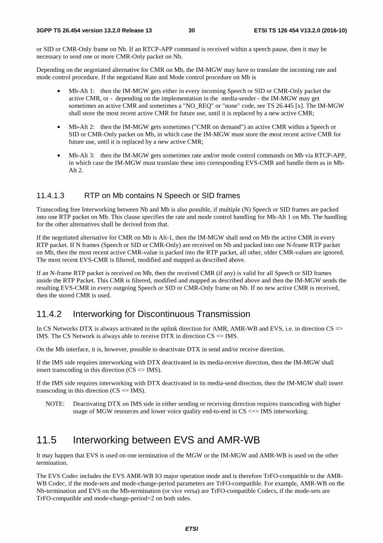
ETSI
ETSI TS 126 454 V13.2.0 (2016-10)303GPP TS 26.454 version 13.2.0 Release 13
or SID or CMR-Only frame on Nb. If an RTCP-APP command is received within a speech pause, then it may be necessary to send one or more CMR-Only packet on Nb.
Depending on the negotiated alternative for CMR on Mb, the IM-MGW may have to translate the incoming rate and mode control procedure. If the negotiated Rate and Mode control procedure on Mb is
• Mb-Alt 1: then the IM-MGW gets either in every incoming Speech or SID or CMR-Only packet the active CMR, or - depending on the implementation in the media-sender - the IM-MGW may get sometimes an active CMR and sometimes a "NO_REQ" or "none" code, see TS 26.445 [x]. The IM-MGW shall store the most recent active CMR for future use, until it is replaced by a new active CMR;
• Mb-Alt 2: then the IM-MGW gets sometimes ("CMR on demand") an active CMR within a Speech or SID or CMR-Only packet on Mb, in which case the IM-MGW must store the most recent active CMR for future use, until it is replaced by a new active CMR;
• Mb-Alt 3: then the IM-MGW gets sometimes rate and/or mode control commands on Mb via RTCP-APP, in which case the IM-MGW must translate these into corresponding EVS-CMR and handle them as in Mb-Alt 2.
11.4.1.3 RTP on Mb contains N Speech or SID frames
Transcoding free Interworking between Nb and Mb is also possible, if multiple (N) Speech or SID frames are packed into one RTP packet on Mb. This clause specifies the rate and mode control handling for Mb-Alt 1 on Mb. The handling for the other alternatives shall be derived from that.
If the negotiated alternative for CMR on Mb is Alt-1, then the IM-MGW shall send on Mb the active CMR in every RTP packet. If N frames (Speech or SID or CMR-Only) are received on Nb and packed into one N-frame RTP packet on Mb, then the most recent active CMR-value is packed into the RTP packet, all other, older CMR-values are ignored. The most recent EVS-CMR is filtered, modified and mapped as described above.
If an N-frame RTP packet is received on Mb, then the received CMR (if any) is valid for all Speech or SID frames inside the RTP Packet. This CMR is filtered, modified and mapped as described above and then the IM-MGW sends the resulting EVS-CMR in every outgoing Speech or SID or CMR-Only frame on Nb. If no new active CMR is received, then the stored CMR is used.
11.4.2 Interworking for Discontinuous Transmission
In CS Networks DTX is always activated in the uplink direction for AMR, AMR-WB and EVS, i.e. in direction CS => IMS. The CS Network is always able to receive DTX in direction CS <= IMS.
On the Mb interface, it is, however, possible to deactivate DTX in send and/or receive direction.
If the IMS side requires interworking with DTX deactivated in its media-receive direction, then the IM-MGW shall insert transcoding in this direction (CS => IMS).
If the IMS side requires interworking with DTX deactivated in its media-send direction, then the IM-MGW shall insert transcoding in this direction (CS <= IMS).
NOTE: Deactivating DTX on IMS side in either sending or receiving direction requires transcoding with higher usage of MGW resources and lower voice quality end-to-end in CS <=> IMS interworking.
11.5 Interworking between EVS and AMR-WB It may happen that EVS is used on one termination of the MGW or the IM-MGW and AMR-WB is used on the other termination.
The EVS Codec includes the EVS AMR-WB IO major operation mode and is therefore TrFO-compatible to the AMR-WB Codec, if the mode-sets and mode-change-period parameters are TrFO-compatible. For example, AMR-WB on the Nb-termination and EVS on the Mb-termination (or vice versa) are TrFO-compatible Codecs, if the mode-sets are TrFO-compatible and mode-change-period=2 on both sides.
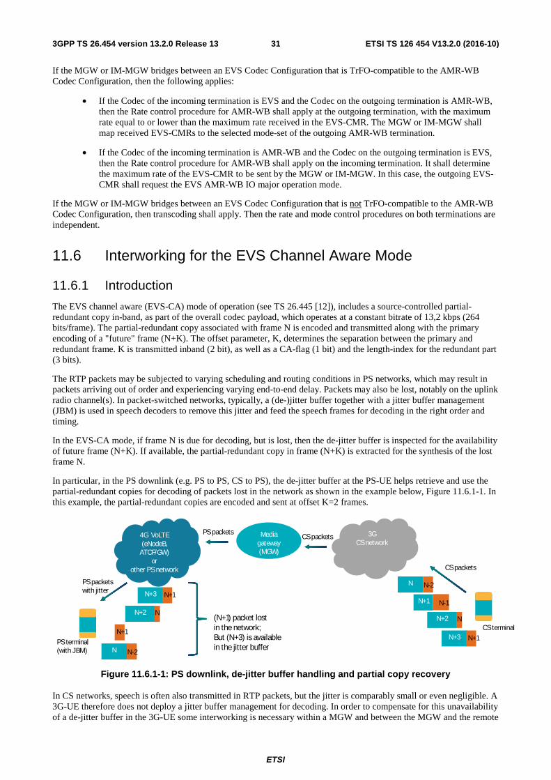
ETSI
ETSI TS 126 454 V13.2.0 (2016-10)313GPP TS 26.454 version 13.2.0 Release 13
If the MGW or IM-MGW bridges between an EVS Codec Configuration that is TrFO-compatible to the AMR-WB Codec Configuration, then the following applies:
• If the Codec of the incoming termination is EVS and the Codec on the outgoing termination is AMR-WB, then the Rate control procedure for AMR-WB shall apply at the outgoing termination, with the maximum rate equal to or lower than the maximum rate received in the EVS-CMR. The MGW or IM-MGW shall map received EVS-CMRs to the selected mode-set of the outgoing AMR-WB termination.
• If the Codec of the incoming termination is AMR-WB and the Codec on the outgoing termination is EVS, then the Rate control procedure for AMR-WB shall apply on the incoming termination. It shall determine the maximum rate of the EVS-CMR to be sent by the MGW or IM-MGW. In this case, the outgoing EVS-CMR shall request the EVS AMR-WB IO major operation mode.
If the MGW or IM-MGW bridges between an EVS Codec Configuration that is not TrFO-compatible to the AMR-WB Codec Configuration, then transcoding shall apply. Then the rate and mode control procedures on both terminations are independent.
11.6 Interworking for the EVS Channel Aware Mode
11.6.1 Introduction
The EVS channel aware (EVS-CA) mode of operation (see TS 26.445 [12]), includes a source-controlled partial-redundant copy in-band, as part of the overall codec payload, which operates at a constant bitrate of 13,2 kbps (264 bits/frame). The partial-redundant copy associated with frame N is encoded and transmitted along with the primary encoding of a "future" frame (N+K). The offset parameter, K, determines the separation between the primary and redundant frame. K is transmitted inband (2 bit), as well as a CA-flag (1 bit) and the length-index for the redundant part (3 bits).
The RTP packets may be subjected to varying scheduling and routing conditions in PS networks, which may result in packets arriving out of order and experiencing varying end-to-end delay. Packets may also be lost, notably on the uplink radio channel(s). In packet-switched networks, typically, a (de-)jitter buffer together with a jitter buffer management (JBM) is used in speech decoders to remove this jitter and feed the speech frames for decoding in the right order and timing.
In the EVS-CA mode, if frame N is due for decoding, but is lost, then the de-jitter buffer is inspected for the availability of future frame (N+K). If available, the partial-redundant copy in frame (N+K) is extracted for the synthesis of the lost frame N.
In particular, in the PS downlink (e.g. PS to PS, CS to PS), the de-jitter buffer at the PS-UE helps retrieve and use the partial-redundant copies for decoding of packets lost in the network as shown in the example below, Figure 11.6.1-1. In this example, the partial-redundant copies are encoded and sent at offset K=2 frames.
Figure 11.6.1-1: PS downlink, de-jitter buffer handling and partial copy recovery
In CS networks, speech is often also transmitted in RTP packets, but the jitter is comparably small or even negligible. A 3G-UE therefore does not deploy a jitter buffer management for decoding. In order to compensate for this unavailability of a de-jitter buffer in the 3G-UE some interworking is necessary within a MGW and between the MGW and the remote
4G VoLTE(eNodeB,
ATCF/GW)or
other PS network
3G CS network
PS terminal(with JBM)
CS terminal
Media gateway (MGW)
CS packets
CS packetsPS packets
PS packets with jitter
N
N+1
N+2
N+3
N-2
N-1
N
N+1
N N-2
N+2 N
N+3 N+1
N+1
(N+1) packet lost in the network;But (N+3) is available in the jitter buffer
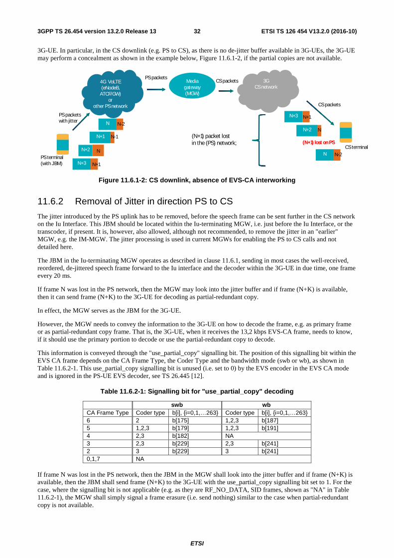
ETSI
ETSI TS 126 454 V13.2.0 (2016-10)323GPP TS 26.454 version 13.2.0 Release 13
3G-UE. In particular, in the CS downlink (e.g. PS to CS), as there is no de-jitter buffer available in 3G-UEs, the 3G-UE may perform a concealment as shown in the example below, Figure 11.6.1-2, if the partial copies are not available.
Figure 11.6.1-2: CS downlink, absence of EVS-CA interworking
11.6.2 Removal of Jitter in direction PS to CS
The jitter introduced by the PS uplink has to be removed, before the speech frame can be sent further in the CS network on the Iu Interface. This JBM should be located within the Iu-terminating MGW, i.e. just before the Iu Interface, or the transcoder, if present. It is, however, also allowed, although not recommended, to remove the jitter in an "earlier" MGW, e.g. the IM-MGW. The jitter processing is used in current MGWs for enabling the PS to CS calls and not detailed here.
The JBM in the Iu-terminating MGW operates as described in clause 11.6.1, sending in most cases the well-received, reordered, de-jittered speech frame forward to the Iu interface and the decoder within the 3G-UE in due time, one frame every 20 ms.
If frame N was lost in the PS network, then the MGW may look into the jitter buffer and if frame (N+K) is available, then it can send frame (N+K) to the 3G-UE for decoding as partial-redundant copy.
In effect, the MGW serves as the JBM for the 3G-UE.
However, the MGW needs to convey the information to the 3G-UE on how to decode the frame, e.g. as primary frame or as partial-redundant copy frame. That is, the 3G-UE, when it receives the 13,2 kbps EVS-CA frame, needs to know, if it should use the primary portion to decode or use the partial-redundant copy to decode.
This information is conveyed through the "use_partial_copy" signalling bit. The position of this signalling bit within the EVS CA frame depends on the CA Frame Type, the Coder Type and the bandwidth mode (swb or wb), as shown in Table 11.6.2-1. This use_partial_copy signalling bit is unused (i.e. set to 0) by the EVS encoder in the EVS CA mode and is ignored in the PS-UE EVS decoder, see TS 26.445 [12].
Table 11.6.2-1: Signalling bit for "use_partial_copy" decoding
swb wb CA Frame Type Coder type b[i], {i=0,1,…263} Coder type b[i], {i=0,1,…263} 6 2 b[175] 1,2,3 b[187] 5 1,2,3 b[179] 1,2,3 b[191] 4 2,3 b[182] NA 3 2,3 b[229] 2,3 b[241] 2 3 b[229] 3 b[241] 0,1,7 NA
If frame N was lost in the PS network, then the JBM in the MGW shall look into the jitter buffer and if frame (N+K) is available, then the JBM shall send frame (N+K) to the 3G-UE with the use_partial_copy signalling bit set to 1. For the case, where the signalling bit is not applicable (e.g. as they are RF_NO_DATA, SID frames, shown as "NA" in Table 11.6.2-1), the MGW shall simply signal a frame erasure (i.e. send nothing) similar to the case when partial-redundant copy is not available.
4G VoLTE(eNodeB,
ATCF/GW)or
other PS network
3G CS network
PS terminal(with JBM)
CS terminal
Media gateway (MGW)
CS packets
CS packetsPS packets
PS packets with jitter
N+3
N+2
N
N+1
(N+1) lost on PS
N
N-2
N+3 N+1
N+1 N-1
N N-2
(N+1) packet lost in the (PS) network;
N+2 N
ETSI
ETSI TS 126 454 V13.2.0 (2016-10)333GPP TS 26.454 version 13.2.0 Release 13
The handling within the 3G-UE is described in clause 7.4.
In some corner cases, it may well be that a call is setup between a PS-UE1 and a 3G-UE2, until the 3G-UE2 is transferred (by handover, SRVCC, DRVCC) into a PS-domain (e.g. LTE or Wi-Fi). The CS network and the Iu-terminating CS-MGW remain in the call path. In such a case, the Iu-terminating CS-MGW, after performing the User Plane switch to the PS domain, shall delete the received frame with this signalling bit set to1, getting back to the situation before the first JBM. Just the first PS-uplink jitter is removed by the first JBM, but the stream of speech frames after the CS-MGW is the same again as before the first JBM.
11.6.3 Removal of Jitter in direction CS to PS
Since the CS-network does not introduce jitter (or only comparably small jitter) and since the PS-network introduces and handles jitter anyway in the PS-UE, there is no need for any jitter removal in the direction CS to PS in a MGW.
The EVS-CA Mode of operation in the direction CS to PS is helpful to mitigate frame losses on the sending CS uplink and the receiving PS downlink, if the JBM is located in the PS-UE.

ETSI
ETSI TS 126 454 V13.2.0 (2016-10)343GPP TS 26.454 version 13.2.0 Release 13
Annex A (informative): Change history
Change history Date Meeting TDoc CR Rev Cat Subject/Comment New
version 2016-03 SA#71 SP-160072 Presented to TSG SA#71 (for approval) 1.0.0 2016-03 SA#71 Approved at TSG SA#71 13.0.0 2016-06 SA#72 SP-160261 000
2 - F Changes to clause 5 RAB Aspects 13.1.0
2016-06 SA#72 SP-160261 0003
1 F Mb Interface User Plane 13.1.0
2016-09 SA#73 SP-160592 0005
- F Correction in clause 4 General for EVSoCS 13.2.0
2016-09 SA#73 SP-160592 0006
1 F Filtering and Modification of EVS-CMR 13.2.0
2016-09 SA#73 SP-160592 0007
1 F Interworking between different EVS Configurations 13.2.0
2016-09 SA#73 SP-160592 0008
1 F Handling of Speech and SID payload 13.2.0
2016-09 SA#73 SP-160592 0009
- F Interworking between EVS and AMR-WB 13.2.0
2016-09 SA#73 SP-160592 0010
- F Correction to clause 6 Iu interface for EVSoCS 13.2.0
2016-09 SA#73 SP-160592 0011
- F Uu Interface User Plane for EVSoCS 13.2.0
2016-09 SA#73 SP-160592 0012
- F Nb Interface for EVSoCS 13.2.0
2016-09 SA#73 SP-160592 0013
1 F Interworking between Nb and Mb 13.2.0
2016-09 SA#73 SP-160592 0014
- F Clarification to avoid rate adaptation quality issues in uplink for UTRAN
13.2.0

ETSI
ETSI TS 126 454 V13.2.0 (2016-10)353GPP TS 26.454 version 13.2.0 Release 13
History
Document history
V13.0.0 May 2016 Publication
V13.1.0 August 2016 Publication
V13.2.0 October 2016 Publication