ts 129 274 - v8.1.1 - universal mobile telecommunications ... · pdf fileuniversal mobile...
TRANSCRIPT

ETSI TS 129 274 V8.1.1 (2009-04)
Technical Specification
Universal Mobile Telecommunications System (UMTS);LTE;
3GPP Evolved Packet System (EPS);Evolved General Packet Radio Service (GPRS)
Tunnelling Protocol for Control plane (GTPv2-C);Stage 3
(3GPP TS 29.274 version 8.1.1 Release 8)

ETSI
ETSI TS 129 274 V8.1.1 (2009-04) 1 3GPP TS 29.274 version 8.1.1 Release 8
Reference RTS/TSGC-0429274v811
Keywords LTE, UMTS
ETSI
650 Route des Lucioles F-06921 Sophia Antipolis Cedex - FRANCE
Tel.: +33 4 92 94 42 00 Fax: +33 4 93 65 47 16
Siret N° 348 623 562 00017 - NAF 742 C
Association à but non lucratif enregistrée à la Sous-Préfecture de Grasse (06) N° 7803/88
Important notice
Individual copies of the present document can be downloaded from: http://www.etsi.org
The present document may be made available in more than one electronic version or in print. In any case of existing or perceived difference in contents between such versions, the reference version is the Portable Document Format (PDF).
In case of dispute, the reference shall be the printing on ETSI printers of the PDF version kept on a specific network drive within ETSI Secretariat.
Users of the present document should be aware that the document may be subject to revision or change of status. Information on the current status of this and other ETSI documents is available at
http://portal.etsi.org/tb/status/status.asp
If you find errors in the present document, please send your comment to one of the following services: http://portal.etsi.org/chaircor/ETSI_support.asp
Copyright Notification
No part may be reproduced except as authorized by written permission. The copyright and the foregoing restriction extend to reproduction in all media.
© European Telecommunications Standards Institute 2009.
All rights reserved.
DECTTM, PLUGTESTSTM, UMTSTM, TIPHONTM, the TIPHON logo and the ETSI logo are Trade Marks of ETSI registered for the benefit of its Members.
3GPPTM is a Trade Mark of ETSI registered for the benefit of its Members and of the 3GPP Organizational Partners. LTE™ is a Trade Mark of ETSI currently being registered
for the benefit of its Members and of the 3GPP Organizational Partners. GSM® and the GSM logo are Trade Marks registered and owned by the GSM Association.

ETSI
ETSI TS 129 274 V8.1.1 (2009-04) 2 3GPP TS 29.274 version 8.1.1 Release 8
Intellectual Property Rights IPRs essential or potentially essential to the present document may have been declared to ETSI. The information pertaining to these essential IPRs, if any, is publicly available for ETSI members and non-members, and can be found in ETSI SR 000 314: "Intellectual Property Rights (IPRs); Essential, or potentially Essential, IPRs notified to ETSI in respect of ETSI standards", which is available from the ETSI Secretariat. Latest updates are available on the ETSI Web server (http://webapp.etsi.org/IPR/home.asp).
Pursuant to the ETSI IPR Policy, no investigation, including IPR searches, has been carried out by ETSI. No guarantee can be given as to the existence of other IPRs not referenced in ETSI SR 000 314 (or the updates on the ETSI Web server) which are, or may be, or may become, essential to the present document.
Foreword This Technical Specification (TS) has been produced by ETSI 3rd Generation Partnership Project (3GPP).
The present document may refer to technical specifications or reports using their 3GPP identities, UMTS identities or GSM identities. These should be interpreted as being references to the corresponding ETSI deliverables.
The cross reference between GSM, UMTS, 3GPP and ETSI identities can be found under http://webapp.etsi.org/key/queryform.asp.

ETSI
ETSI TS 129 274 V8.1.1 (2009-04) 3 3GPP TS 29.274 version 8.1.1 Release 8
Contents
Intellectual Property Rights ................................................................................................................................2
Foreword.............................................................................................................................................................2
Foreword.............................................................................................................................................................7
1 Scope ........................................................................................................................................................8
2 References ................................................................................................................................................8
3 Definitions, symbols and abbreviations ...................................................................................................9 3.1 Definitions..........................................................................................................................................................9 3.2 Symbols............................................................................................................................................................10 3.3 Abbreviations ...................................................................................................................................................10
4 General ...................................................................................................................................................11 4.1 GTP Tunnel ......................................................................................................................................................11 4.2 Protocol stack ...................................................................................................................................................11 4.2.1 UDP header and port numbers....................................................................................................................12 4.2.1.1 Initial Messages.....................................................................................................................................12 4.2.1.2 Triggered Messages ..............................................................................................................................12 4.2.2 IP header and IP addresses..........................................................................................................................12 4.2.2.1 Initial Messages.....................................................................................................................................12 4.2.2.2 Triggered Messages ..............................................................................................................................12 4.2.3 Layer 2 ........................................................................................................................................................12 4.2.4 Layer 1 ........................................................................................................................................................12 4.3 Transmission Order and Bit Definitions...........................................................................................................13
5 GTP Header for Control Plane ...............................................................................................................13 5.1 General format..................................................................................................................................................13 5.2 Control Plane GTP Extension Header ..............................................................................................................13 5.3 GTP-C header for Echo and Version Not Supported messages .......................................................................13 5.4 EPC specific GTP-C header .............................................................................................................................14 5.5 Usage of the GTPv2-C Header.........................................................................................................................14 5.6 Format of the GTPv2-C Message.....................................................................................................................15
6 GTP-C Message Types and Message Formats.......................................................................................16 6.1 Message Format and Type values ....................................................................................................................16 6.1.1 Presence requirements of Information Elements ........................................................................................18 6.1.2 Grouped Information Elements...................................................................................................................18 6.1.3 Information Element instance .....................................................................................................................19 6.2 Message Granularity.........................................................................................................................................19
7 GTP-C messages ....................................................................................................................................20 7.1 Path Management Messages.............................................................................................................................20 7.1.1 Echo Request ..............................................................................................................................................20 7.1.2 Echo Response............................................................................................................................................20 7.1.3 Version Not Supported Indication ..............................................................................................................20 7.2 Tunnel Management Messages ........................................................................................................................20 7.2.1 Create Session Request ...............................................................................................................................21 7.2.2 Create Session Response ............................................................................................................................24 7.2.3 Create Bearer Request ................................................................................................................................27 7.2.4 Create Bearer Response ..............................................................................................................................28 7.2.5 Bearer Resource Command ........................................................................................................................29 7.2.6 Bearer Resource Failure Indication ............................................................................................................30 7.2.7 Modify Bearer Request ...............................................................................................................................31 7.2.8 Modify Bearer Response ............................................................................................................................34 7.2.9 Delete Session Request and Delete Bearer Request ...................................................................................37 7.2.9.1 Delete Session Request .........................................................................................................................37 7.2.9.2 Delete Bearer Request...........................................................................................................................38

ETSI
ETSI TS 129 274 V8.1.1 (2009-04) 4 3GPP TS 29.274 version 8.1.1 Release 8
7.2.10 Delete Session Response and Delete Bearer Response...............................................................................39 7.2.10.1 Delete Session Response.......................................................................................................................39 7.2.10.2 Delete Bearer Response ........................................................................................................................40 7.2.11 Downlink Data Notification messages........................................................................................................41 7.2.11.1 Downlink Data Notification ..................................................................................................................41 7.2.11.2 Downlink Data Notification Acknowledgement ...................................................................................42 7.2.11.3 Downlink Data Notification Failure Indication.....................................................................................42 7.2.12 Delete Indirect Data Forwarding Tunnel Request ......................................................................................43 7.2.13 Delete Indirect Data Forwarding Tunnel Response ....................................................................................43 7.2.14 Modify Bearer Command and Failure Indication .......................................................................................43 7.2.14.1 Modify Bearer Command .....................................................................................................................43 7.2.14.2 Modify Bearer Failure Indication..........................................................................................................44 7.2.15 Update Bearer Request ...............................................................................................................................45 7.2.16 Update Bearer Response .............................................................................................................................46 7.2.17 Delete Bearer Command and Failure Indication.........................................................................................47 7.2.17.1 Delete Bearer Command .......................................................................................................................47 7.2.17.2 Delete Bearer Failure Indication ...........................................................................................................48 7.2.18 Create Indirect Data Forwarding Tunnel Request ......................................................................................49 7.2.19 Create Indirect Data Forwarding Tunnel Response ....................................................................................50 7.2.20 Update Bearer Complete.............................................................................................................................51 7.2.21 Release Access Bearers Request.................................................................................................................52 7.2.22 Release Access Bearers Response ..............................................................................................................52 7.2.23 Stop Paging Indication................................................................................................................................52 7.3 Mobility Management Messages......................................................................................................................53 7.3.1 Forward Relocation Request.......................................................................................................................53 7.3.2 Forward Relocation Response ....................................................................................................................55 7.3.3 Forward Relocation Complete Notification................................................................................................57 7.3.4 Forward Relocation Complete Acknowledge .............................................................................................58 7.3.5 Context Request..........................................................................................................................................58 7.3.6 Context Response .......................................................................................................................................59 7.3.7 Context Acknowledge.................................................................................................................................61 7.3.8 Identification Request .................................................................................................................................62 7.3.9 Identification Response...............................................................................................................................63 7.3.10 Forward Access Context Notification.........................................................................................................63 7.3.11 Forward Access Context Acknowledge......................................................................................................64 7.3.12 Detach Notification.....................................................................................................................................64 7.3.13 Detach Acknowledge..................................................................................................................................65 7.3.14 Change Notification Request ......................................................................................................................66 7.3.15 Change Notification Response....................................................................................................................66 7.3.16 Relocation Cancel Request .........................................................................................................................67 7.3.17 Relocation Cancel Response.......................................................................................................................67 7.3.18 Configuration Transfer Tunnel ...................................................................................................................68 7.3.19 RAN Information Relay..............................................................................................................................68 7.4 CS Fallback related messages ..........................................................................................................................68 7.4.1 Suspend Notification...................................................................................................................................68 7.4.2 Suspend Acknowledge................................................................................................................................69 7.4.3 Resume Notification ...................................................................................................................................69 7.4.4 Resume Acknowledge ................................................................................................................................69 7.4.5 CS Paging Indication ..................................................................................................................................69 7.5 Non-3GPP access related messages .................................................................................................................70 7.5.1 Create Forwarding Tunnel Request ............................................................................................................70 7.5.2 Create Forwarding Tunnel Response..........................................................................................................70 7.6 Reliable Delivery of Signalling Messages........................................................................................................71 7.7 Error Handling..................................................................................................................................................72 7.7.1 Protocol Errors............................................................................................................................................72 7.7.2 Different GTP Versions ..............................................................................................................................72 7.7.3 GTP Message of Invalid Length .................................................................................................................72 7.7.4 Unknown GTP Message .............................................................................................................................73 7.7.5 Unexpected GTP Message..........................................................................................................................73 7.7.6 Missing Information Elements....................................................................................................................73 7.7.7 Invalid Length Information Element ..........................................................................................................73 7.7.8 Semantically incorrect Information Element ..............................................................................................74

ETSI
ETSI TS 129 274 V8.1.1 (2009-04) 5 3GPP TS 29.274 version 8.1.1 Release 8
7.7.9 Unknown or unexpected Information Element ...........................................................................................74 7.7.10 Repeated Information Elements..................................................................................................................74 7.8 Path Failure ......................................................................................................................................................74 7.9 Restoration and Recovery ................................................................................................................................75 7.9.1 Delete PDN Connection Set Request..........................................................................................................75 7.9.2 Delete PDN Connection Set Response .......................................................................................................75 7.10 Fallback to GTPv1 mechanism ........................................................................................................................76 7.11 Fallback to GTPv0............................................................................................................................................76 7.12 Trace Management Messages...........................................................................................................................76 7.12.1 Trace Session Activation ............................................................................................................................76 7.12.2 Trace Session Deactivation.........................................................................................................................76
8 GTP-C Information Elements ................................................................................................................77 8.1 Information Element Types..............................................................................................................................77 8.2 Information Element Format ............................................................................................................................79 8.3 International Mobile Subscriber Identity (IMSI)..............................................................................................79 8.4 Cause ................................................................................................................................................................79 8.5 Recovery (Restart Counter)..............................................................................................................................81 8.6 Access Point Name (APN) ...............................................................................................................................82 8.7 Aggregate Maximum Bit Rate (AMBR) ..........................................................................................................82 8.8 EPS Bearer ID (EBI) ........................................................................................................................................82 8.9 IP Address ........................................................................................................................................................83 8.10 Mobile Equipment Identity (MEI)....................................................................................................................83 8.11 MSISDN...........................................................................................................................................................83 8.12 Indication..........................................................................................................................................................84 8.13 Protocol Configuration Options (PCO) ............................................................................................................85 8.14 PDN Address Allocation (PAA) ......................................................................................................................85 8.15 Bearer Quality of Service (Bearer QoS)...........................................................................................................86 8.16 Flow Quality of Service (Flow QoS)................................................................................................................86 8.17 RAT Type.........................................................................................................................................................86 8.18 Serving Network ..............................................................................................................................................87 8.19 EPS Bearer Level Traffic Flow Template (Bearer TFT)..................................................................................87 8.20 Traffic Aggregate Description (TAD)..............................................................................................................88 8.21 User Location Info (ULI) .................................................................................................................................88 8.21.1 CGI field .....................................................................................................................................................88 8.21.2 SAI field .....................................................................................................................................................89 8.21.3 RAI field .....................................................................................................................................................89 8.21.4 TAI field .....................................................................................................................................................89 8.21.5 ECGI field...................................................................................................................................................90 8.22 Fully Qualified TEID (F-TEID) .......................................................................................................................90 8.23 TMSI ................................................................................................................................................................91 8.24 Global CN-Id....................................................................................................................................................92 8.25 S103 PDN Data Forwarding Info (S103PDF) ..................................................................................................92 8.26 S1-U Data Forwarding (S1UDF)......................................................................................................................92 8.27 Delay Value......................................................................................................................................................93 8.28 Bearer Context..................................................................................................................................................93 8.29 Charging ID......................................................................................................................................................94 8.30 Charging Characteristics ..................................................................................................................................94 8.31 Trace Information.............................................................................................................................................95 8.32 Bearer Flags......................................................................................................................................................95 8.33 Paging Cause ....................................................................................................................................................96 8.34 PDN Type.........................................................................................................................................................96 8.35 Procedure Transaction ID (PTI) .......................................................................................................................96 8.36 DRX Parameter ................................................................................................................................................96 8.37 UE Network Capability ....................................................................................................................................97 8.38 MM Context .....................................................................................................................................................97 8.39 PDN Connection ............................................................................................................................................102 8.40 PDU Numbers ................................................................................................................................................103 8.41 Packet TMSI (P-TMSI) ..................................................................................................................................104 8.42 P-TMSI Signature...........................................................................................................................................104 8.43 Hop Counter ...................................................................................................................................................104 8.44 UE Time Zone ................................................................................................................................................105

ETSI
ETSI TS 129 274 V8.1.1 (2009-04) 6 3GPP TS 29.274 version 8.1.1 Release 8
8.45 Trace Reference..............................................................................................................................................105 8.46 Complete Request Message............................................................................................................................105 8.47 GUTI ..............................................................................................................................................................106 8.48 Fully Qualified Container (F-Container) ........................................................................................................106 8.49 Fully Qualified Cause (F-Cause)....................................................................................................................107 8.50 Selected PLMN ID .........................................................................................................................................107 8.51 Target Identification .......................................................................................................................................107 8.52 NSAPI ............................................................................................................................................................107 8.53 Packet Flow ID...............................................................................................................................................108 8.54 RAB Context ..................................................................................................................................................108 8.55 Source RNC PDCP context info.....................................................................................................................109 8.56 UDP Source Port Number ..............................................................................................................................109 8.57 APN Restriction .............................................................................................................................................109 8.58 Selection Mode...............................................................................................................................................110 8.59 Source Identification ......................................................................................................................................110 8.60 Bearer Control Mode......................................................................................................................................110 8.61 Change Reporting Action ...............................................................................................................................111 8.62 Fully qualified PDN Connection Set Identifier (FQ-CSID) ...........................................................................111 8.63 Channel needed ..............................................................................................................................................112 8.64 eMLPP Priority ..............................................................................................................................................112 8.65 Node Type ......................................................................................................................................................113 8.66 Fully Qualified Domain Name (FQDN).........................................................................................................113 8.67 Private Extension............................................................................................................................................113
9 Security.................................................................................................................................................114
10 IP - The Networking Technology used by GTP...................................................................................114 10.1 IP Version.......................................................................................................................................................114 10.2 IP Fragmentation ............................................................................................................................................114
Annex A (informative): Change History ............................................................................................115
History ............................................................................................................................................................117
ETSI
ETSI TS 129 274 V8.1.1 (2009-04) 7 3GPP TS 29.274 version 8.1.1 Release 8
Foreword This Technical Specification has been produced by the 3rd Generation Partnership Project (3GPP).
The contents of the present document are subject to continuing work within the TSG and may change following formal TSG approval. Should the TSG modify the contents of the present document, it will be re-released by the TSG with an identifying change of release date and an increase in version number as follows:
Version x.y.z
where:
x the first digit:
1 presented to TSG for information;
2 presented to TSG for approval;
3 or greater indicates TSG approved document under change control.
y the second digit is incremented for all changes of substance, i.e. technical enhancements, corrections, updates, etc.
z the third digit is incremented when editorial only changes have been incorporated in the document.

ETSI
ETSI TS 129 274 V8.1.1 (2009-04) 8 3GPP TS 29.274 version 8.1.1 Release 8
1 Scope The present document specifies the stage 3 of the control plane of the GPRS Tunnelling Protocol, Version 2 for Evolved Packet System interfaces (GTPv2-C).
In this document, unless otherwise specified the S5 interface refers always to "GTP-based S5" and S8 interface refers always to "GTP-based S8" interface.
GTPv2-C shall be used across the following EPC signalling interfaces: S3, S4, S5, S8, S10, S11 and S16.
GTPv2-C based protocols shall also be used across Sv (3GPP TS 29.280 [15]) and S101 (3GPP TS 29.276 [14]) interfaces.
2 References The following documents contain provisions which, through reference in this text, constitute provisions of the present document.
• References are either specific (identified by date of publication, edition number, version number, etc.) or non-specific.
• For a specific reference, subsequent revisions do not apply.
• For a non-specific reference, the latest version applies. In the case of a reference to a 3GPP document (including a GSM document), a non-specific reference implicitly refers to the latest version of that document in the same Release as the present document.
[1] 3GPP TR 21.905: "Vocabulary for 3GPP Specifications".
[2] 3GPP TS 23.003: "Numbering, addressing and identification".
[3] 3GPP TS 23.401: "General Packet Radio Service (GPRS) enhancements for Evolved Universal Terrestrial Radio Access Network (E-UTRAN) access".
[4] 3GPP TS 29.060: "General Packet Radio Service (GPRS); GPRS Tunnelling Protocol (GTP) across the Gn and Gp interface".
[5] 3GPP TS 24.008: "Mobile radio interface Layer 3 specification; Core network protocols; Stage 3".
[6] IETF RFC 791 (STD 0005): "Internet Protocol", J. Postel.
[7] IETF RFC 768 (STD 0006): "User Datagram Protocol", J. Postel.
[8] 3GPP TS 32.251: "Telecommunication Management; Charging Management; Packet Switched (PS) domain charging.
[9] 3GPP TS 32.298: "Telecommunication Management; Charging Management; Charging Data Record (CDR) parameter classification.
[10] 3GPP TS 36.413: "Evolved Universal Terrestrial Radio Access Network (E-UTRAN); S1 Application Protocol (S1AP)".
[11] 3GPP TS 33.102: "3G security; Security architecture".
[12] 3GPP TS 33.401: "3GPP System Architecture Evolution (SAE); Security architecture".
[13] 3GPP TS 29.281: "GPRS Tunnelling Protocol User Plane (GTPv1-U)".
[14] 3GPP TS 29.276: "Optimized Handover Procedures and Protocols between E-UTRAN Access and cdma2000 HRPD Access – Stage 3".
[15] 3GPP TS 29.280: "3GPP EPS Sv interface (MME to MSC) for SRVCC".

ETSI
ETSI TS 129 274 V8.1.1 (2009-04) 9 3GPP TS 29.274 version 8.1.1 Release 8
[16] IETF RFC 2460: "Internet Protocol, Version 6 (IPv6) Specification".
[17] 3GPP TS 23.007: "Restoration procedures".
[18] 3GPP TS 32.422: "Telecommunication management; Subscriber and equipment trace; Trace control and configuration management ".
[19] 3GPP TS 36.300: "Evolved Universal Terrestrial Radio Access (E-UTRA) and Evolved Universal Terrestrial Radio Access Network (E-UTRAN); Overall description; Stage 2".
[20] 3GPP TS 36.414: "Evolved Universal Terrestrial Radio Access Network (E-UTRAN); S1 data transport".
[21] 3GPP TS 23.272: "Circuit switched fallback in Evolved Packet System; Stage 2".
[22] 3GPP TS 29.118: "Mobility Management Entity (MME) - Visitor Location Register (VLR) SGs interface specification ".
[23] 3GPP TS 24.301: "Non-Access-Stratum (NAS) protocol for Evolved Packet".
[24] 3GPP TS 33.210: "Network Domain Security; IP network layer security".
[25] ITU-T Recommendation E.164: "The international public telecommunication numbering plan".
[26] 3GPP TS 29.275: "Proxy Mobile IPv6 (PMIPv6) based Mobility and Tunnelling protocols; Stage 3"
[27] 3GPP TS 44.018: "Mobile radio interface layer 3 specification; Radio Resource Control Protocol".
[28] 3GPP TS 48.008: "Mobile-services Switching Centre - Base Station System (MSC-BSS) interface; Layer 3 specification".
3 Definitions, symbols and abbreviations
3.1 Definitions For the purposes of the present document, the terms and definitions given in TR 21.905 [1] and the following apply. A term defined in the present document takes precedence over the definition of the same term, if any, in TR 21.905 [1].
GTP-PDU: GTP Protocol Data Unit is either a GTP-C Message or a GTP-U Message. GTP-U Message may be either a signalling message across the user plane tunnel, or a G-PDU (see clause 6).
• Signalling Message: any GTP-PDU (GTP-C or GTP-U) except the G-PDU.
• G-PDU: GTP user plane message, which carries the original packet (payload). G-PDU consists of GTP-U header and a T-PDU.
• T-PDU: original packet, for example an IP datagram, from an UE or a network node in an external packet data network. A T-PDU is the payload that is tunnelled in the GTP-U tunnel.
• GTP-C Message: GTP control plane message type of a GTP-PDU. GTP-C message consists of GTP-C header, which is followed by zero or more information elements.
• GTP-U Message: GTP user plane message. The user plane messages are used to carry user data packets, and also signalling messages e.g. for path management and error indication. Therefore, GTP-U message consists of GTP-U header, which is followed by either a T-PDU, or zero or more information elements.
GTP Tunnel: FFS (see also subclause 4.1 "GTP Tunnel").
Tunnel Endpoint: A tunnel endpoint is identified with a TEID, an IP address and a UDP port number (see subclause 4.1 "GTP Tunnel").

ETSI
ETSI TS 129 274 V8.1.1 (2009-04) 103GPP TS 29.274 version 8.1.1 Release 8
Tunnel Endpoint Identifier (TEID): unambiguously identifies a tunnel endpoint in scope of a path (see subclause 4.1 "GTP Tunnel").
3.2 Symbols For the purposes of the present document, the following symbols apply:
S1-U Interface between SGW and eNodeB X2 Interface between eNodeBs
3.3 Abbreviations For the purposes of the present document, the abbreviations given in TR 21.905 [1] and the following apply. An abbreviation defined in the present document takes precedence over the definition of the same abbreviation, if any, in TR 21.905 [1].
AMBR Aggregate Maximum Bit Rate APN Access Point Name APN-NI Access Point Name Network Identifier APN-OI Access Point Name Operator Identifier EBI EPS Bearer ID eNodeB Evolved Node B EPC Evolved Packet Core EPS Evolved Packet System F-TEID Fully Qualified Tunnel Endpoint Identifier G-PDU GTP-U non-signalling PDU GPRS General Packet Radio Service GTP GPRS Tunnelling Protocol GTP-PDU GTP-C PDU or GTP-U PDU GTPv2-C GTP version 2, control plane GTPv2-U GTP version 2, user plane IMSI International Mobile Subscriber Identity IP Internet Protocol LBI Linked Bearer identity L1 Layer 1 L2 Layer 2 MEI Mobile Equipment Identity MSISDN Mobile Subscriber ISDN Number PAA PDN Address Allocation PCO Protocol Configuration Options PDU Protocol Data Unit PDN Packet Data Network or Public Data Network PGW PDN Gateway PTI Procedure Transaction Id QoS Quality of Service RAT Radio Access Type SGW Serving Gateway TEID Tunnel Endpoint Identifier TEID-C Tunnel Endpoint Identifier, control plane TEID-U Tunnel Endpoint Identifier, user plane TFT Traffic Flow Template TLIV Type Length Instance Value UDP User Datagram Protocol ULI User Location Info RIM RAN Information Management

ETSI
ETSI TS 129 274 V8.1.1 (2009-04) 113GPP TS 29.274 version 8.1.1 Release 8
4 General
4.1 GTP Tunnel GTP tunnels are used between two nodes communicating over a GTP based interface, to separate traffic into different communication flows.
A GTP tunnel is identified in each node with a TEID, an IP address and a UDP port number. The receiving end side of a GTP tunnel locally assigns the TEID value the transmitting side has to use. The TEID values are exchanged between tunnel endpoints using GTP-C or S1-MME messages.
The criteria defining when the same or different GTP tunnels shall be used between to nodes differs between the control and the user plane, and also between interfaces.
For the control plane, for each end-point of a GTP-C tunnel:
- The TEID-C shall be unique per PDN-Connection on GTP based S5 and S8 interfaces. The same tunnel shall be shared for the control messages related to all bearers associated to the PDN-Connection. A TEID-C on the S5/S8 interface shall be released after all its associated EPS bearers are deleted.
- There shall be only one pair of TEID-Cs per UE on each of the S3 and the S10 interfaces. The same tunnel shall be shared for the control messages related to the same UE operation. A TEID-C on the S3/S10 interface shall be released after its associated UE context is removed or the UE is detached.
- There shall be only one pair of TEID-C per UE over the S11 and the S4 interfaces. The same tunnel shall be shared for the control messages related to the same UE operation. A TEID-C on the S11/S4 interface shall be released after all its associated EPS bearers are deleted.
For GTP-U, a TEID-U is used according to 3GPP TS 29.281 [13].
NOTE: GTP-U is based on GTP version 1 (GTPv1).
4.2 Protocol stack The protocol stack for GTPv2 shall be as depicted in Figure 4.2-1.
GTP
UDP
IP
L2
L1
GTP
UDP
IP
L2
L1
GTPv2 entity GTPv2 entity
GTPv2 based interface
Figure 4.2-1: GTPv2 stack

ETSI
ETSI TS 129 274 V8.1.1 (2009-04) 123GPP TS 29.274 version 8.1.1 Release 8
The GTPv2 headers are specified in the respective clauses of this specification.
The source and destination IP addresses and UDP ports used for each GTP-C message depend on the role that the message plays in a message exchange. Messages can be initial messages, or triggered messages. An initial message is sent to a peer GTP entity with a sequence number chosen by the sending entity (see subclause 7.6). Triggered messages are sent in response to an initial message or to another triggered message.
NOTE: Examples of initial messages are all command or notification messages. Examples of triggered messages are all responses or acknowledge messages as well as Version Not Supported Indication and Update Bearer Complete.
Some request messages are initial messages in some procedures, but triggered messages in other procedures where they are triggered by an initial command message.
Piggybacked messages are handled as triggered messages.
4.2.1 UDP header and port numbers
A User Datagram Protocol (UDP) compliant with IETF RFC 768 [7] shall be used.
4.2.1.1 Initial Messages
The UDP Destination Port number for GTP-C request messages shall be 2123. It is the registered port number for GTP-C.
The UDP Source Port is a locally allocated port number at the sending GTP entity.
4.2.1.2 Triggered Messages
The UDP Destination Port value shall be the value of the UDP Source Port of the corresponding request message.
The UDP Source Port shall be the value from the UDP Destination Port of the corresponding request message.
4.2.2 IP header and IP addresses
4.2.2.1 Initial Messages
The IP Source Address shall be an IP address of the source GTPv2 entity from which the message is originating.
The IP Destination Address in a GTP request message shall be an IP address of the destination GTPv2 entity.
4.2.2.2 Triggered Messages
The IP Source Address shall be copied from the IP destination address of the GTP request message to which this GTPv2 entity is replying.
The IP Destination Address shall be copied from the IP Source Address of the GTP request message to which this GTPv2 entity is replying.
4.2.3 Layer 2
Typically Ethernet should be used as a Layer 2 protocol, but operators may use any other technology.
4.2.4 Layer 1
Operators may use any appropriate Layer 1 technology.

ETSI
ETSI TS 129 274 V8.1.1 (2009-04) 133GPP TS 29.274 version 8.1.1 Release 8
4.3 Transmission Order and Bit Definitions The messages in this document shall be transmitted in network octet order starting with octet 1 with the Most Significant Bit sent first.
The most significant bit of an octet in a GTP message is bit 8. If a value in a GTP message spans several octets and nothing else is stated, the most significant bit is bit 8 of the octet with the lowest number.
5 GTP Header for Control Plane
5.1 General format Control Plane GTP uses a variable length header. Control Plane GTP header length shall be a multiple of 4 octets. Figure 5.1-1 illustrates the format of the GTPv2-C Header.
Bits Octets 8 7 6 5 4 3 2 1
1 Version P T Spare Spare Spare 2 Message Type 3 Message Length (1st Octet) 4 Message Length (2nd Octet)
m to k(m+3)
If T flag is set to 1, then TEID shall be placed into octets 5-8. Otherwise, TEID field is not present at all.
n to (n+1) Sequence Number (n+2) to
(n+3) Spare
Figure 5.1-1: General format of GTPv2 Header for Control Plane
Where:
- if T = 0, TEID field is not present, k = 0, m = 0 and n = 5;
- if T = 1, TEID field is present, k = 1, m = 5 and n = 9.
The usage of GTPv2-C header across the EPC specific interfaces is defined in the subclause 5.5 "Usage of the GTPv2-C Header". Octet 1 bits shall be coded as follows:
- Bits 6-8 represent the Version field.
- Bit 5 represents the Piggybacking flag (P).
- Bit 4 represents the TEID flag (T).
- Bits 3-1 are spare, the sender shall set it to zero and the receiver shall ignore it.
5.2 Control Plane GTP Extension Header The legacy Extension Header mechanism is not used for the GTP version 2 control plane (GTPv2-C). Future extensions will be implemented by adding Information Elements in the message body if new parameters are needed.
5.3 GTP-C header for Echo and Version Not Supported messages
The GTPv2-C message header for the Echo Request, Echo Response and Version Not Supported Indication messages shall not contain the TEID field, but shall contain the Sequence Number fields, followed by two spare octets as depicted in figure 5.3-1. The spare bits shall be set to zero by the sender and ignored by the receiver.

ETSI
ETSI TS 129 274 V8.1.1 (2009-04) 143GPP TS 29.274 version 8.1.1 Release 8
Bits Octets 8 7 6 5 4 3 2 1
1 Version P T=0 Spare Spare Spare 2 Message Type 3 Message Length (1st Octet) 4 Message Length (2nd Octet) 5 Sequence Number (1st Octet) 6 Sequence Number (2nd Octet) 7 Spare 8 Spare
Figure 5.3-1: The format of Echo and Version Not Supported message Header
5.4 EPC specific GTP-C header Apart from the Echo Request, Echo Response and Version Not Supported Indication messages, the GTP-C message header shall contain the TEID and Sequence Number fields, followed by two spare octets. A typical GTP-C header is depicted in figure 5.4-1. The spare bits shall be set to zero by the sender and ignored by the receiver.
Bits Octets 8 7 6 5 4 3 2 1
1 Version P T=1 Spare Spare Spare 2 Message Type 3 Message Length (1st Octet) 4 Message Length (2nd Octet) 5 Tunnel Endpoint Identifier (1st Octet) 6 Tunnel Endpoint Identifier (2nd Octet) 7 Tunnel Endpoint Identifier (3rd Octet) 8 Tunnel Endpoint Identifier (4th Octet) 9 Sequence Number (1st Octet)
10 Sequence Number (2nd Octet) 11 Spare 12 Spare
Figure 5.4-1: The format of EPC specific GTPv2 Control Plane message Header
5.5 Usage of the GTPv2-C Header The format of the GTPv2-C header is specified in subclause 5.1 "General format". The usage of the GTP-C header across e.g. S101 (3GPP TS 29.276 [14]) and Sv (3GPP TS 29.280 [15]) interfaces are defined in their respective specifications.
The usage of the GTPv2-C header for EPC specific interfaces shall be as defined below.
The first octet of the header shall be used is the following way:
- Bits 8 to 6, which represent the GTP-C version, shall be set to decimal 2 ("010").
- Bit 5"" represents a "P" flag. If the "P" flag is set to "0", no piggybacked message shall be present. If the "P" flag is set to "1", then another GTPv2-C message with its own header and body shall be present at the end of the current message. If Create Session Response message (as part of EUTRAN initial attach or UE-requested PDN connectivity procedure) has the "P" flag set to "1", then a Create Bearer Request message shall be present as the piggybacked message. If Modify Bearer Request (as part of EUTRAN initial attach or UE-requested PDN connectivity procedure) has the "P" flag set to "1", then Create Bearer Response shall be present as the piggybacked message. Apart from these messages, all the EPC specific messages shall have the "P" flag set to "0".
- Bit 4 represents a "T" flag, which indicates if TEID field is present in the GTP-C header or not. If the "T" flag is set to 0, then the TEID field shall not be present in the GTP-C header. If the "T" flag is set to 1, then the TEID field shall immediately follow the Length field, in octets 5 to 8. Apart from the Echo Request, Echo Response and Version Not Supported messages, in all EPC specific messages the value of the "T" flag shall be set to "1".
- Bit 3 is a spare bit. The sending entity shall set it to "0" and the receiving entity shall ignore it.

ETSI
ETSI TS 129 274 V8.1.1 (2009-04) 153GPP TS 29.274 version 8.1.1 Release 8
- Bit 2 is a spare bit. The sending entity shall set it to "0" and the receiving entity shall ignore it.
- Bit 1 is a spare bit. The sending entity shall set it to "0" and the receiving entity shall ignore it.
The usage of the fields in octets 2 - n of the header shall be as specified below.
- Octet 2 represents the Message type field, which shall be set to the unique value for each type of control plane message. Message type values are specified in Table 6.1-1 "Message types for GTPv2".
- Octets 3 to 4 represent the Length field. This field shall indicate the length of the message in octets excluding the mandatory part of the GTP-C header (the first 4 octets). The TEID (if present) and the Sequence Number shall be included in the length count. The format of the Length field is specified in subclause 8.2 "Information Element Format".
- For EPC specific interfaces, T=1, and therefore octets 5 to 8 represent the Tunnel Endpoint Identifier (TEID) field. This field shall unambiguously identify a tunnel endpoint in the receiving GTP-C entity. The Tunnel Endpoint Identifier is set by the sending entity to the value provided by the corresponding receiving entity. When a peer's TEID is not available, as in the following cases, the TEID field shall be present in a GTPv2-C header, but its value shall be set to "0":
• Create Session Request message on S5/S8
• Create Session Request message on S4/S11, if for a given UE, the SGSN/MME has not yet obtained the Control TEID of the SGW.
• Identification Request/Response messages.
• Change Notification Request/Response messages.
• Forward Relocation Request message.
• Context Request message.
• Detach Notification/Acknowledge messages.
• Relocation Cancel Request message except for the case where the old SGSN/MME has already been assigned the Tunnel Endpoint Identifier Control Plane of the new SGSN/MME.
• Delete PDN Connection Set Request/Response messages.
• If a node receives a message for which it has no context, it shall respond with “Context not found” Cause in the corresponding response message to the sender. The TEID used in the GTPv2-C header in the response message shall be set to zero.
- Octets 9 to 10 represent GTP Sequence Number field.
5.6 Format of the GTPv2-C Message The GTP-C header may be followed by subsequent information elements dependent on the type of control plane message.
Bits Octets 8 7 6 5 4 3 2 1 1 to m GTP-C header m+1 to n Zero or more Information Element(s)
Figure 5.6-1: GTP-C Header followed by subsequent Information Elements

ETSI
ETSI TS 129 274 V8.1.1 (2009-04) 163GPP TS 29.274 version 8.1.1 Release 8
6 GTP-C Message Types and Message Formats A GTP-C message is sent across a GTP control plane tunnel. In a message, the GTP-C header is followed by zero or more information elements. The GTP-C messages are used for the control plane path management, for the control plane tunnel management and for mobility management.
A T-PDU is an original packet, for example an IP datagram, from an UE, or from a network node in an external packet data network.
6.1 Message Format and Type values GTP defines a set of messages between two associated EPC network elements. The messages to be used shall be as defined in Table 6.1-1.

ETSI
ETSI TS 129 274 V8.1.1 (2009-04) 173GPP TS 29.274 version 8.1.1 Release 8
Table 6.1-1: Message types for GTPv2
Message Type value (Decimal)
Message Reference GTP-C GTP-U
0 Reserved 1 Echo Request X X 2 Echo Response X X 3 Version Not Supported Indication X
4 to 24 Reserved for S101 interface TS 29.276 [14] 25 to 31 Reserved for Sv interface TS 29.280 [15]
SGSN/MME to PGW (S4/S11, S5/S8) 32 Create Session Request X 33 Create Session Response X 34 Modify Bearer Request X 35 Modify Bearer Response X 36 Delete Session Request X 37 Delete Session Response X 38 Change Notification Request X 39 Change Notification Response X
40 to 63 For future use Messages without explicit response
64 Modify Bearer Command (MME/SGSN to PGW –S11/S4, S5/S8)
X
65 Modify Bearer Failure Indication (PGW to MME/SGSN –S5/S8, S11/S4)
X
66 Delete Bearer Command (MME to PGW –S11, S5/S8)
X
67 Delete Bearer Failure Indication (PGW to MME –S5/S8, S11) X 68 Bearer Resource Command
(MME/SGSN to PGW –S11/S4, S5/S8) X
69 Bearer Resource Failure Indication (PGW to MME/SGSN –S5/S8, S11/S4)
X
70 Downlink Data Notification Failure Indication (SGSN/MME to SGW –S4/S11)
X
71 Trace Session Activation X 72 Trace Session Deactivation X 73 Stop Paging Indication X
74 to 94 For future use PGW to SGSN/MME (S5/S8, S4/S11)
95 Create Bearer Request X 96 Create Bearer Response X 97 Update Bearer Request X 98 Update Bearer Response X 99 Delete Bearer Request X
100 Delete Bearer Response X 101 to 127 For future use
MME to MME, SGSN to MME, MME to SGSN, SGSN to SGSN (S3/10/S16)
128 Identification Request X 129 Identification Response X 130 Context Request X 131 Context Response X 132 Context Acknowledge X 133 Forward Relocation Request X 134 Forward Relocation Response X 135 Forward Relocation Complete Notification X 136 Forward Relocation Complete Acknowledge X 137 Forward Access Context Notification X 138 Forward Access Context Acknowledge X 139 Relocation Cancel Request X 140 Relocation Cancel Response X 141 Configuration Transfer Tunnel X
142 to 148 For future use SGSN to MME, MME to SGSN (S3)
149 Detach Notification X 150 Detach Acknowledge X

ETSI
ETSI TS 129 274 V8.1.1 (2009-04) 183GPP TS 29.274 version 8.1.1 Release 8
Message Type value (Decimal)
Message Reference GTP-C GTP-U
151 CS Paging Indication X 152 RAN Information Relay
153 to 159 For future use MME to SGW (S11)
160 Create Forwarding Tunnel Request X 161 Create Forwarding Tunnel Response X 162 Suspend Notification X 163 Suspend Acknowledge X 164 Resume Notification X 165 Resume Acknowledge X 166 Create Indirect Data Forwarding Tunnel Request X 167 Create Indirect Data Forwarding Tunnel Response X 168 Delete Indirect Data Forwarding Tunnel Request X 169 Delete Indirect Data Forwarding Tunnel Response X 170 Release Access Bearers Request X 171 Release Access Bearers Response X
172 to 175 For future use SGW to SGSN/MME (S4/S11)
176 Downlink Data Notification X 177 Downlink Data Notification Acknowledgement X 178 Update Bearer Complete X
179 to 191 For future use Other
192 to 255 For future use
6.1.1 Presence requirements of Information Elements
There are three different presence requirements (Mandatory, Conditional, or Optional) for an IE within a given GTP-PDU:
- Mandatory means that the IE shall be included by the sending side, and that the receiver diagnoses a "Mandatory IE missing" error, when detecting that the IE is not present. A response including a "Mandatory IE missing" cause, shall include the type of the missing IE.
- Conditional means:
- that inclusion of the IE by the sender depends on conditions specified in the relevant protocol specification;
Editor's Note: the receiver shall check the conditions as specified in the corresponding message type description, based on the parameter combination in the message and/or on the state of the receiving node, to infer if a conditional IE shall be expected. Only if a conditional IE, which is absolutely necessary for the receiving entity to complete the procedure, is missing, then the receiver shall abort the procedure.
- Optional means that the IE shall be included as a service option. Therefore, the IE may be included or not in a message.
For conditional IEs, the clause describing the GTP-PDU explicitly defines the conditions under which each IE becomes mandatory or optional for that particular GTP-PDU. These conditions shall be defined so that the presence of a conditional IE only becomes mandatory if it is critical for the receiving entity. The definition might reference other protocol specifications for final terms used as part of the condition.
Editor's Note: This definition of conditions shall be done per conditional IE in a dedicated column of the table listing the IEs for that GTP-PDU.
6.1.2 Grouped Information Elements
Information elements can contain other IEs. This type of IE is called "Grouped IEs".
Grouped IEs have a length value in the TLIV encoding, which includes the added length of all the embedded IEs. Overall coding of a grouped information element with 4 octets long IE header is defined in subclause 8.2 "Information Element Format". Each information element within a grouped IE also shall also contain 4 octets long IE header.

ETSI
ETSI TS 129 274 V8.1.1 (2009-04) 193GPP TS 29.274 version 8.1.1 Release 8
The flexibility of having optional, conditional or a variable number of embedded fields within an IE is not provided by non-grouped IEs and it is due to the usage of TLIV encoded fields. This flexibility also allows using one and the same type of grouped IEs for different messages and slightly different purposes, as long as the main purpose of the IE type is the same. It is encouraged to define grouped IEs in a flexible way to minimize the number of types needed.
Grouped IEs are not marked by any flag or limited to a specific range of IE type values. The clause describing an IE in this specification shall explicitly state if it is grouped.
NOTE: Each entry into each Grouped IE creates a new scope level. Exit from the grouped IE closes the scope level. The GTPv2 message level is the top most scope. This is analogous to the local scope of a subroutine/function.
6.1.3 Information Element instance
Every GTPv2 message and grouped IE within a message in this specification has a column documenting the instance value of each IE.
When a GTPv2 message is encoded for use the instance value of each included IE is encoded in the Instance field of the IE for the message scope. See clause 7 and subclause 8.2 for details of that encoding.
An Information Element in an encoded GTPv2 message or encoded grouped IE is identified by the pair of IE Type and Instance values and described by a specific row in the corresponding tables in subclauses of 7 in the present document.
If several Information Elements with the same Type and Instance values are included in an encoded GTPv2 message, they represent a list for the corresponding IE name and row identified in the message grammar in subclauses of clause 7.
If several Information Elements with the same Type and Instance values are included in an encoded grouped IE, they represent a list for the corresponding IE name and row identified in the grouped IE grammar in subclauses of clause 7.
In tables in this document the instance value for "Private Extension" is marked as VS (Vendor Specific). While an instance value must be encoded by the sender the value can be Vendor and even Private Extension specific.
The same IE name might be used in different messages (on the top level or within grouped IEs) in this specification. The instance value and name of an IE is only meaningful within the scope of the message definition . The combination of Type value and Instance value uniquely identifies a specific row in a message description table.
6.2 Message Granularity The GTPv2-C messages shall be sent per UE on the S3, S10 and S16 interfaces.
The GTPv2-C messages shall be sent per PDN-Connection on the S4 and S11 interfaces apart from the following exclusion.
The following GTPv2-C messages are sent per UE on the S4 and S11 interfaces:
- Downlink Data Notification/Acknowledgement.
- Stop Paging.
- Delete Indirect Data Forwarding Tunnel Request/Response.
- Delete Session Request only during the S1-based handover procedure with SGW relocation or the X2-based handover procedure with SGW relocation.
- Release Access Bearers Request/Response.

ETSI
ETSI TS 129 274 V8.1.1 (2009-04) 203GPP TS 29.274 version 8.1.1 Release 8
7 GTP-C messages
7.1 Path Management Messages Three path management messages are specified for GTP-C: Echo Request, Echo Response and Version Not Supported Indication.
7.1.1 Echo Request
3GPP TS 23.007 [17] specifies that a GTP-C entity may send an Echo Request to find out if the peer entity is alive. When and how often an Echo Request message may be sent is implementation specific but an Echo Request shall not be sent more often than every 60 s on each path. This does not prevent resending an Echo Request with the same sequence number according to the T3-RESPONSE timer.
As an implementation option, it is recommended that Echo Request should be sent only when a GTP-C entity has not received any GTP response message for a previously sent request message on the GTP-C path for the above specified, implementation dependent period of time.
Table 7.1.1-1 specifies the information elements included in the Echo Request message.
The optional Private Extension contains vendor or operator specific information.
Table 7.1.1-1: Information Elements in Echo Request
Information elements
P Condition / Comment IE Type Ins.
Recovery M Recovery 0 Private Extension O Private Extension VS
7.1.2 Echo Response
3GPP TS 23.007 [17] specifies that a GTP-C entity shall be prepared to receive an Echo Request at any time and it shall reply with an Echo Response.
Table 7.1.2-1 specifies the information elements included in the Echo Response message.
The Recovery information element contains the local Restart Counter, which is specified in 3GPP TS 23.007 [17])
The optional Private Extension contains vendor or operator specific information.
Table 7.1.2-1: Information Elements in Echo Response
Information elements
P Condition / Comment IE Type Ins.
Recovery M Recovery 0 Private Extension O Private Extension VS
7.1.3 Version Not Supported Indication
This message contains only the GTPv2 header and indicates the latest GTP version that the sending entity supports.
7.2 Tunnel Management Messages A node shall include the Recovery information element if it is in contact with the peer for the first time or the node has restarted recently and the new Restart Counter value has not yet been indicated to the peer. The peer receiving the Recovery information element shall handle it as when an Echo Response message is received but shall consider the rest of the message in accordance with the message semantics and parameters.
ETSI
ETSI TS 129 274 V8.1.1 (2009-04) 213GPP TS 29.274 version 8.1.1 Release 8
Editor Note: The CSID Information Element for partial failure handling is specified for some of the messages. The rest of the messages that may need to carry the CSID IE are FFS.
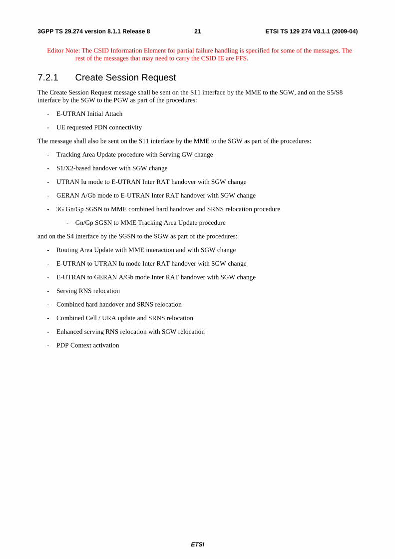
7.2.1 Create Session Request
The Create Session Request message shall be sent on the S11 interface by the MME to the SGW, and on the S5/S8 interface by the SGW to the PGW as part of the procedures:
- E-UTRAN Initial Attach
- UE requested PDN connectivity
The message shall also be sent on the S11 interface by the MME to the SGW as part of the procedures:
- Tracking Area Update procedure with Serving GW change
- S1/X2-based handover with SGW change
- UTRAN Iu mode to E-UTRAN Inter RAT handover with SGW change
- GERAN A/Gb mode to E-UTRAN Inter RAT handover with SGW change
- 3G Gn/Gp SGSN to MME combined hard handover and SRNS relocation procedure
- Gn/Gp SGSN to MME Tracking Area Update procedure
and on the S4 interface by the SGSN to the SGW as part of the procedures:
- Routing Area Update with MME interaction and with SGW change
- E-UTRAN to UTRAN Iu mode Inter RAT handover with SGW change
- E-UTRAN to GERAN A/Gb mode Inter RAT handover with SGW change
- Serving RNS relocation
- Combined hard handover and SRNS relocation
- Combined Cell / URA update and SRNS relocation
- Enhanced serving RNS relocation with SGW relocation
- PDP Context activation

ETSI
ETSI TS 129 274 V8.1.1 (2009-04) 223GPP TS 29.274 version 8.1.1 Release 8
Table 7.2.1-1: Information Elements in a Create Session Request
Information elements
P Condition / Comment IE Type Ins.
IMSI M IMSI 0 MSISDN C For an E-UTRAN Initial Attach the IE shall be included
when used on the S11 interface, if provided in the subscription data from the HSS and it shall be included when used on the S5/S8 interfaces if provided by the MME. The IE shall be included for the case of a UE Requested PDN Connectivity, it shall be included if the MME has it stored for that UE.
MSISDN 0
ME Identity (MEI) C The MME shall include the ME Identity (MEI) IE, if it is available.
MEI 0
User Location Info (ULI)
C This IE shall be included for E-UTRAN access. It shall include ECGI&TAI.
ULI 0
Serving Network C This IE shall be included for an E-UTRAN initial attach and for a UE requested PDN connectivity.
Serving Network 0
RAT Type M RAT Type 0 Indication Flags C Applicable flags are:
• S5/S8 Protocol Indicator: This flag shall be used on the S11/S4 interfaces and set according to the protocol chosen to be used on the S5/S8 interfaces.
• Dual Address Bearer Flag: This flag shall be set to 1 when the UE requests a PDN type IPv4v6 and all SGSNs which the UE may be handed over to support dual addressing. This shall be determined based on node pre-configuration by the operator.
• Handover Indication: This flag shall be set in an E-UTRAN Initial Attach or in a UE Requested PDN Connectivity, if the UE comes from non-3GPP access.
• Operation Indication: This flag shall be set for a TAU/RAU.
• Direct Tunnel Flag: This flag shall be used on the S4 interface and set to 1 if Direct Tunnel is used.
• Piggybacking Supported: This flag shall be set to 1 only if the MME/SGSN/SGW supports the piggybacking feature as described in Annex F of 3GPP TS 23.401 [3].
• Change Reporting support Indication: shall be used on S4/S11, S5/S8 and set if the SGSN/MME supports location Info Change Reporting.
Indication 0
Sender F-TEID for Control Plane
M F-TEID 0
PGW S5/S8 Address for Control Plane or PMIP
C This IE shall be sent on the S11 / S4 interfaces. The TEID or GRE Key is set to "0" in the E-UTRAN initial attach and the UE requested PDN connectivity procedures.
F-TEID 1
Access Point Name (APN)
C This IE shall be included for the TAU/RAU/Handover cases when the S5/S8 Protocol Indicator is set to 1 (PMIP based S5/S8). This IE shall also be included for an E-UTRAN initial attach and a UE requested PDN connectivity.
APN 0
Selection Mode C This IE shall be included for an E-UTRAN initial attach and a UE requested PDN connectivity. It shall indicate whether a subscribed APN or a non subscribed APN chosen by the MME was selected.
Selection Mode 0
PDN Type M This IE shall be set to IPv4, IPv6 or IPv4IPv6. This is based on the subscription record retrieved from the HSS.
PDN Type 0
PDN Address Allocation (PAA)
C This IE shall be included for an E-UTRAN initial attach and a UE requested PDN connectivity. The PDN type field in the PAA shall be set based on the
PAA 0
ETSI
ETSI TS 129 274 V8.1.1 (2009-04) 233GPP TS 29.274 version 8.1.1 Release 8
UE request. For static IP address assignment, the MME shall set the IPv4 address and/or IPv6 prefix length and IPv6 address if available. If static IP address assignment is not used, the the IPv4 address shall be set to 0.0.0.0, and the IPv6 Prefix Length and IPv6 address shall all be set to zero.
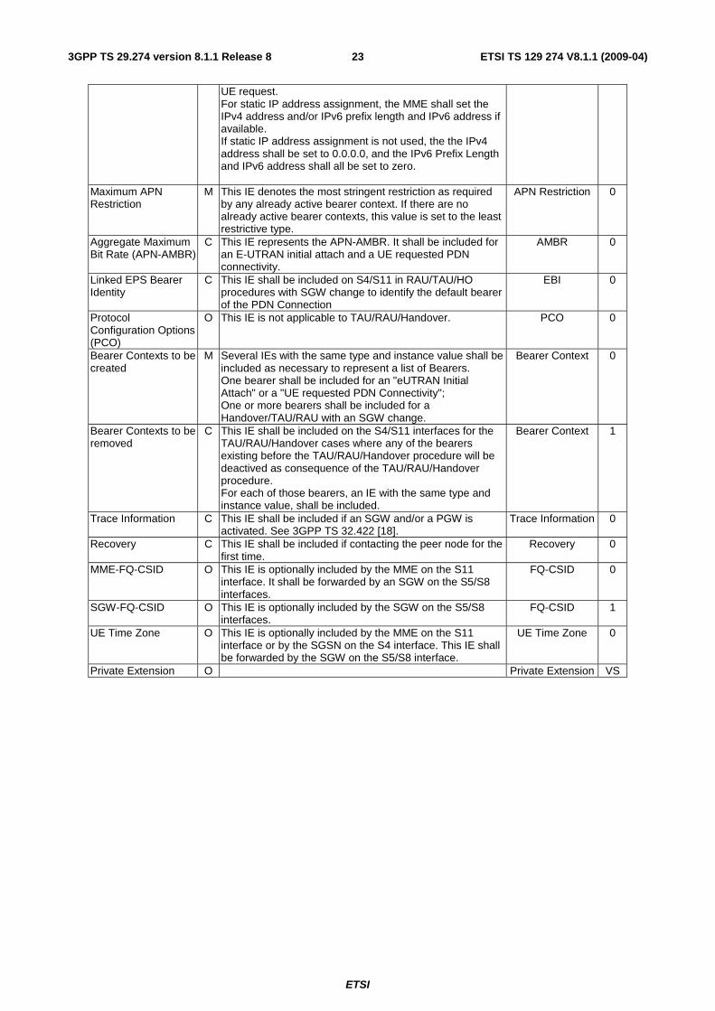
Maximum APN Restriction
M This IE denotes the most stringent restriction as required by any already active bearer context. If there are no already active bearer contexts, this value is set to the least restrictive type.
APN Restriction 0
Aggregate Maximum Bit Rate (APN-AMBR)
C This IE represents the APN-AMBR. It shall be included for an E-UTRAN initial attach and a UE requested PDN connectivity.
AMBR 0
Linked EPS Bearer Identity
C This IE shall be included on S4/S11 in RAU/TAU/HO procedures with SGW change to identify the default bearer of the PDN Connection
EBI 0
Protocol Configuration Options (PCO)
O This IE is not applicable to TAU/RAU/Handover. PCO 0
Bearer Contexts to be created
M Several IEs with the same type and instance value shall be included as necessary to represent a list of Bearers. One bearer shall be included for an "eUTRAN Initial Attach" or a "UE requested PDN Connectivity"; One or more bearers shall be included for a Handover/TAU/RAU with an SGW change.
Bearer Context 0
Bearer Contexts to be removed
C This IE shall be included on the S4/S11 interfaces for the TAU/RAU/Handover cases where any of the bearers existing before the TAU/RAU/Handover procedure will be deactived as consequence of the TAU/RAU/Handover procedure. For each of those bearers, an IE with the same type and instance value, shall be included.
Bearer Context 1
Trace Information C This IE shall be included if an SGW and/or a PGW is activated. See 3GPP TS 32.422 [18].
Trace Information 0
Recovery C This IE shall be included if contacting the peer node for the first time.
Recovery 0
MME-FQ-CSID O This IE is optionally included by the MME on the S11 interface. It shall be forwarded by an SGW on the S5/S8 interfaces.
FQ-CSID 0
SGW-FQ-CSID O This IE is optionally included by the SGW on the S5/S8 interfaces.
FQ-CSID 1
UE Time Zone O This IE is optionally included by the MME on the S11 interface or by the SGSN on the S4 interface. This IE shall be forwarded by the SGW on the S5/S8 interface.
UE Time Zone 0
Private Extension O Private Extension VS

ETSI
ETSI TS 129 274 V8.1.1 (2009-04) 243GPP TS 29.274 version 8.1.1 Release 8
Table 7.2.1-2: Bearer Context to be created within Create Session Request
Octet 1 Bearer Context IE Type = 93 (decimal) Octets 2 and 3 Length = n Octet 4 Spare and Instance fields
Information elements
P Condition / Comment IE Type Ins.
EPS Bearer ID M EBI 0 UL TFT O Bearer TFT 0 DL TFT O Bearer TFT 1 S1-U eNodeB F-TEID C This IE shall be included on the S11 interface for an
eUTRAN handover/TAU. F-TEID 0
S4-U SGSN F-TEID C This IE shall be included on the S4 interface if the S4-U interface is used.
F-TEID 1
S5/8-U SGW F-TEID C This IE shall be included on the S5/S8 interface for an "eUTRAN Initial Attach" or a "UE Requested PDN Connectivity".
F-TEID 2
S5/8-U PGW F-TEID C This IE shall be included on the S4 and S11 interfaces for the TAU/RAU/Handover cases when the GTP-based S5/S8 is used.
F-TEID 3
Bearer Level QoS M Bearer QoS 0 Charging Characteristics
C This IE shall be included according to 3GPP TS 32.251 [8] Charging Characteristics
0
Charging ID C This IE shall be included on the S11/S4 interfaces for the TAU/RAU/Handover cases.
Charging ID 0
Bearer Flags O Applicable flags are: • PPC (Prohibit Payload Compression)
Bearer Flags 0
Table 7.2.1-3: Bearer Context to be removed within Create Session Request
Octet 1 Bearer Context IE Type = 93 (decimal) Octets 2 and 3 Length = n Octet 4 Spare and Instance fields
Information elements
P Condition / Comment IE Type Ins.
EPS Bearer ID M EBI 0 S4-U SGSN F-TEID C This IE shall be sent on the S4 interface if the S4-U
interface is used. F-TEID 0
7.2.2 Create Session Response
The Create Session Response message shall be sent on the S11 interface by the SGW to the MME, and on the S5/S8 interface by the PGW to the SGW as part of the procedures:
- E-UTRAN Initial Attach
- UE requested PDN connectivity
The message shall also be sent on the S11 interface by the SGW to the MME as part of the procedures:
- Tracking Area Update procedure with SGW change
- S1/X2-based handover with SGW change
- UTRAN Iu mode to E-UTRAN Inter RAT handover with SGW change
- GERAN A/Gb mode to E-UTRAN Inter RAT handover with SGW change
- 3G Gn/Gp SGSN to MME combined hard handover and SRNS relocation procedure
- Gn/Gp SGSN to MME Tracking Area Update procedure
and on the S4 interface by the SGW to the SGSN as part of the procedures:

ETSI
ETSI TS 129 274 V8.1.1 (2009-04) 253GPP TS 29.274 version 8.1.1 Release 8
- Routing Area Update with MME interaction and with SGW change
- E-UTRAN to UTRAN Iu mode Inter RAT handover with SGW change
- E-UTRAN to GERAN A/Gb mode Inter RAT handover with SGW change
- Serving RNS relocation
- Combined hard handover and SRNS relocation
- Combined Cell / URA update and SRNS relocation
- Enhanced serving RNS relocation with SGW relocation
- PDP Context activation
If handling of default bearer fails, then cause at the message level shall be a failure cause.

ETSI
ETSI TS 129 274 V8.1.1 (2009-04) 263GPP TS 29.274 version 8.1.1 Release 8
Table 7.2.2-1: Information Elements in a Create Session Response
Information elements
P Condition / Comment IE Type Ins.
Cause M Cause 0 BCM C This IE shall be included if this message is part of the
procedure PDP Context Activation using the S4 interface. Bearer Control
Mode 0
Change Reporting Action
C This IE shall be sent on the S4 interface if the MS Info Change Reporting mechanism is to be used for this subscriber in the SGSN.
Change Reporting Action
0
Sender F-TEID for Control Plane
C This IE shall be sent on the S11/S4 interfaces. For the S5/S8 interfaces it is not needed because its content would be identical to the IE PGW S5/S8 Address for Control Plane or PMIP.
F-TEID 0
PGW S5/S8 Address for Control Plane or PMIP
C This IE shall include the TEID in the GTP based S5/S8 case and the GRE key in the PMIP based S5/S8 case.
F-TEID 1
PDN Address Allocation (PAA)
C This IE shall be included for the E-UTRAN initial attach and the UE requested PDN connectivity.
PAA 0
APN Restriction M This IE denotes the restriction on the combination of types of APN for the APN associated with this EPS bearer Context.
APN Restriction 0
Aggregate Maximum Bit Rate (APN-AMBR)
C This IE represents the APN-AMBR. It shall be included if the received APN-AMBR has been modified by the PCRF.
AMBR 0
Linked EPS Bearer Identity
C This IE shall be sent on S4 or S11 when the UE moves from a Gn/Gp SGSN to the S4 SGSN or MME to identify the default bearer the PGW selects for the PDN Connection.
EBI 0
Protocol Configuration Options (PCO)
O This IE is not applicable for TAU/RAU/Handover. PCO 0
Bearer Contexts created
M EPS bearers corresponding to Bearer Contexts sent in request message. Several IEs with the same type and instance value may be included as necessary to represent a list of Bearers. One bearer shall be included for "eUTRAN Initial Attach" or "UE Requested PDN Connectivity". One or more created bearers shall be included for a Handover/TAU with an SGW change.
Bearer Context 0
Bearer Contexts marked for removal
C EPS bearers corresponding to Bearer Contexts to be removed that were sent in the Create Session Request message. For each of those bearers an IE with the same type and instance value shall be included.
Bearer Context 1
Recovery C This IE shall be included if contacting the peer for the first time
Recovery 0
PGW-FQ-CSID O This IE is optionally included by the PGW on the S5/S8 interfaces. It shall be forwarded by the SGW on the S11 interface.
FQ-CSID 0
SGW-FQ-CSID O This IE is optionally included by the SGW on the S11 interface.
FQ-CSID 1
Private Extension O Private Extension VS

ETSI
ETSI TS 129 274 V8.1.1 (2009-04) 273GPP TS 29.274 version 8.1.1 Release 8
Table 7.2.2-2: Bearer Context Created within Create Session Response
Octets 1 Bearer Context IE Type = 93 (decimal) Octets 2 and 3 Length = n Octets 4 Spare and Instance fields
Information elements
P Condition / Comment IE Type Ins.
EPS Bearer ID M EBI 0 Cause M This IE shall indicate if the bearer handling was successful,
and if not, it gives information on the reason. Cause 0
UL TFT O Bearer TFT 0 DL TFT O Bearer TFT 1 S1-U SGW F-TEID C This IE shall be included on the S11 interface if the S1-U
interface is used. F-TEID 0
S4-U SGW F-TEID C This IE shall be included on the S4 interface if the S4-U interface is used.
F-TEID 1
S5/8-U PGW F-TEID C This IE shall be included for an "eUTRAN Initial Attach" or a "UE Requested PDN Connectivity".
F-TEID 2
S12 SGW F-TEID C This IE shall be included on the S4 interface if the S12 interface is used.
F-TEID 3
Bearer Level QoS C This IE shall be included if the received QoS parameters have been modified.
Bearer QoS 0
Charging Id C This IE shall be included for an E-UTRAN initial attach and a UE requested PDN connectivity.
Charging Id 0
Bearer Flags O Applicable flags are: • PPC (Prohibit Payload Compression)
Bearer Flags 0
Table 7.2.2-3: Bearer Context marked for removal within a Create Session Response
Octet 1 Bearer Context IE Type = 93 (decimal) Octets 2 and 3 Length = n Octet 4 Spare and Instance fields
Information elements
P Condition / Comment IE Type Ins.
EPS Bearer ID M EBI 0 Cause M This IE shall indicate if the bearer handling was successful,
and if not, gives the information on the reason. Cause 0
7.2.3 Create Bearer Request
The Create Bearer Request message shall be sent on the S5/S8 interface by the PGW to the SGW and on the S11 interface by the SGW to the MME as part of the Dedicated Bearer Activation procedure.
The message shall also be sent on the S5/S8 interface by the PGW to the SGW and on the S4 interface by the SGW to the SGSN as part of the Secondary PDP Context Activation procedure or the Network Requested Secondary PDP Context Activation procedure.

ETSI
ETSI TS 129 274 V8.1.1 (2009-04) 283GPP TS 29.274 version 8.1.1 Release 8
Table 7.2.3-1: Information Elements in a Create Bearer Request
Information elements
P Condition / Comment IE Type Ins.
Procedure Transaction Id (PTI)
C This IE shall be sent when the procedure was initiated by a UE Requested Bearer Resource Modification Procedure and Secondary PDP Context Activation Procedure. The PTI shall be the same as the one used in the corresponding Bearer Resource Command.
PTI 0
Linked Bearer Identity (LBI)
M This IE shall be used to identify the PDN connection. EBI 0
APN Aggregate Maximum Bit Rate (APN-AMBR)
C This IE shall be included when the P-GW initiates a create bearer procedure for policy updates due to the creation of non-GBR flows.
AMBR 0
Protocol Configuration Options (PCO)
O PCO 0
Bearer Contexts M Several IEs with this type and instance values shall be included as necessary to represent a list of Bearers.
Bearer Context 0
PGW-FQ-CSID O This IE is optionally included by the PGW on the S5/S8 interfaces. It shall be forwarded by the SGW on the S11 interface.
FQ-CSID 0
SGW-FQ-CSID O This IE is optionally included by the SGW on the S11 interface.
FQ-CSID 1
Change Reporting Action
C This IE shall be included with the appropriate Action field If the location Change Reporting mechanism is to be started or stopped for this subscriber in the SGSN/MME.
Change Reporting Action
0
Private Extension O Private Extension VS
Table 7.2.3-2: Bearer Context within Create Bearer Request
Octets 1 Bearer Context IE Type = 93 (decimal) Octets 2 and 3 Length = n Octets 4 Spare and Instance fields
Information elements
P Condition / Comment IE Type Ins.
EPS Bearer ID M This IE shall be set to 0. EBI 0 UL TFT M Bearer TFT 0 DL TFT C This IE shall be sent for PMIP based S5/S8 interfaces. Bearer TFT 1 S1-U SGW F-TEID C This IE shall be sent on the S11 interface if the S1-U
interface is used. F-TEID 0
S5/8-U PGW F-TEID C This IE shall be sent on the S4, S5/S8 and S11 interfaces. F-TEID 1 S12 SGW F-TEID C This IE shall be sent on the S4 interface if the S12
interface is used. F-TEID 2
S4-U SGW F-TEID C This IE shall be sent on the S4 interface if the S4-U interface is used.
F-TEID 3
Bearer Level QoS M Bearer QoS 0 Charging Characteristics
C This IE shall be included according to 3GPP TS 32.251 [8]. Charging Characteristics
0
Charging Id M Charging Id 0 Bearer Flags O Applicable flags are:
• PPC (Prohibit Payload Compression) Bearer Flags 0
7.2.4 Create Bearer Response
The Create Bearer Response message shall be sent on the S5/S8 interface by the SGW to the PGW, and on the S11 interface by the MME to the SGW as part of the Dedicated Bearer Activation procedure.
The message shall also be sent on the S5/S8 interface by the SGW to the PGW and on the S4 interface by the SGSN to the SGW as part of Secondary PDP Context Activation procedure or the Network Requested Secondary PDP Context Activation procedure.
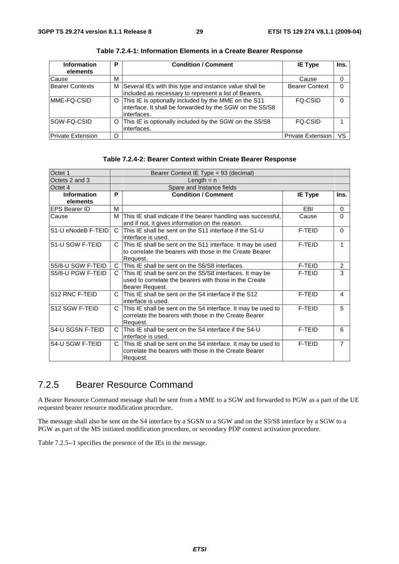
ETSI
ETSI TS 129 274 V8.1.1 (2009-04) 293GPP TS 29.274 version 8.1.1 Release 8
Table 7.2.4-1: Information Elements in a Create Bearer Response
Information elements
P Condition / Comment IE Type Ins.
Cause M Cause 0 Bearer Contexts M Several IEs with this type and instance value shall be
included as necessary to represent a list of Bearers. Bearer Context 0
MME-FQ-CSID O This IE is optionally included by the MME on the S11 interface. It shall be forwarded by the SGW on the S5/S8 interfaces.
FQ-CSID 0
SGW-FQ-CSID O This IE is optionally included by the SGW on the S5/S8 interfaces.
FQ-CSID 1
Private Extension O Private Extension VS
Table 7.2.4-2: Bearer Context within Create Bearer Response
Octet 1 Bearer Context IE Type = 93 (decimal) Octets 2 and 3 Length = n Octet 4 Spare and Instance fields
Information elements
P Condition / Comment IE Type Ins.
EPS Bearer ID M EBI 0 Cause M This IE shall indicate if the bearer handling was successful,
and if not, it gives information on the reason. Cause 0
S1-U eNodeB F-TEID C This IE shall be sent on the S11 interface if the S1-U interface is used.
F-TEID 0
S1-U SGW F-TEID C This IE shall be sent on the S11 interface. It may be used to correlate the bearers with those in the Create Bearer Request.
F-TEID 1
S5/8-U SGW F-TEID C This IE shall be sent on the S5/S8 interfaces. F-TEID 2 S5/8-U PGW F-TEID C This IE shall be sent on the S5/S8 interfaces. It may be
used to correlate the bearers with those in the Create Bearer Request.
F-TEID 3
S12 RNC F-TEID C This IE shall be sent on the S4 interface if the S12 interface is used.
F-TEID 4
S12 SGW F-TEID C This IE shall be sent on the S4 interface. It may be used to correlate the bearers with those in the Create Bearer Request.
F-TEID 5
S4-U SGSN F-TEID C This IE shall be sent on the S4 interface if the S4-U interface is used.
F-TEID 6
S4-U SGW F-TEID C This IE shall be sent on the S4 interface. It may be used to correlate the bearers with those in the Create Bearer Request.
F-TEID 7
7.2.5 Bearer Resource Command
A Bearer Resource Command message shall be sent from a MME to a SGW and forwarded to PGW as a part of the UE requested bearer resource modification procedure.
The message shall also be sent on the S4 interface by a SGSN to a SGW and on the S5/S8 interface by a SGW to a PGW as part of the MS initiated modification procedure, or secondary PDP context activation procedure.
Table 7.2.5--1 specifies the presence of the IEs in the message.

ETSI
ETSI TS 129 274 V8.1.1 (2009-04) 303GPP TS 29.274 version 8.1.1 Release 8
Table 7.2.5-1: Information Elements in a Bearer Resource Command
Information elements
P Condition / Comment IE Type Ins.
Linked EPS Bearer ID (LBI)
M EBI 0
Procedure Transaction Id (PTI)
M PTI 0
Flow Quality of Service (Flow QoS)
C This IE shall not be included for a Bearer resource release. Flow QoS 0
Traffic Aggregate Description (TAD)
M The TAD consists of the description of the packet filter(s) for a traffic flow aggregate.
TAD 0
RAT Type C This IE shall be included for MS initiated PDP Context modification procedure and Secondary PDP context activation procedure.
RAT Type 0
Serving Network O This IE may be included in the MS initiated modification procedure.
Serving Network 0
User Location Information(ULI)
O This IE may be included in the MS initiated modification procedure.
ULI 0
EPS Bearer ID C This IE indicates the EPS Bearer that needs to be modified, it shall be included for MS initiated PDP Context modification procedure
EBI 1
Indication Flags O Applicable flags: • Change Reporting Support Indication: this flag
may be included in the MS initiated modification procedure.
• Direct Tunnel Flag: this flag may be included in the MS initiated modification procedure.
Indication 0
S4-U SGSN F-TEID C This IE shall be included on the S4 interface when direct tunnel is not established in the MS initiated modification procedure
F-TEID 0
S12 RNC F-TEID C This IE shall be included on the S4 interface when direct tunnel flag is set to 1 in the MS initiated modification procedure if
F-TEID 1
Protocol Configuration Options (PCO)
O PCO 0
Private Extension O None Private Extension VS
7.2.6 Bearer Resource Failure Indication
A Bearer Resource Failure Indication shall be sent by the PGW to an SGW and forwarded to the MME to indicate failure of the UE requested bearer resource modification procedure.
The message shall also be sent by a PGW to an SGW and forwarded to an SGSN as part of the failure of an MS initiated modification procedure or secondary PDP context activation procedure.
Table 7.2.6-1 specifies the presence of the IEs in the message.
Possible Cause values are:
- "No resources available".
- "No memory available".
- "Missing or unknown APN".
- "User authentication failed".
- "System failure".
- "Semantic error in the TAD operation".
- "Syntactic error in the TAD operation".
- "Semantic errors in packet filter(s)".

ETSI
ETSI TS 129 274 V8.1.1 (2009-04) 313GPP TS 29.274 version 8.1.1 Release 8
- "Syntactic errors in packet filter(s)".
- "Mandatory IE incorrect".
- "Mandatory IE missing".
- "Optional IE incorrect".
- "Invalid message format".
- "APN access denied – no subscription".
- "Collision with network initiated request".
Table 7.2.6-1: Information Elements in a Bearer Resource Failure Indication
Information elements
P Condition / Comment IE Type Ins.
Cause M Cause 0 Linked EPS Bearer ID M EBI 0 Procedure Transaction ID (PTI)
M PTI 0
Recovery O Recovery 0 Private Extension O Private Extension VS
7.2.7 Modify Bearer Request
The Modify Bearer Request message shall only be sent on the S11 interface by the MME to the SGW and on the S5/S8 interfaces by the SGW to the PGW as part of the procedures:
- E-UTRAN Tracking Area Update without SGW Change
- UE triggered Service Request
- S1-based Handover
- UTRAN Iu mode to E-UTRAN Inter RAT handover
- GERAN A/Gb mode to E-UTRAN Inter RAT handover
- E-UTRAN Initial Attach
- UE requested PDN connectivity
- 3G SGSN to MME combined hard handover and SRNS relocation procedure
It shall also only be sent on the S4 interface by the SGSN to the SGW and on the S5/S8 interfaces by the SGW to the PGW as part of the procedures:
- Routeing Area Update with MME interaction and without SGW change
- Routeing Area Update with MME interaction and with SGW change
- E-UTRAN to UTRAN Iu mode Inter RAT handover
- E-UTRAN to GERAN A/Gb mode Inter RAT handover
- Inter SGSN Routeing Area Update Procedure and Combined Inter SGSN RA / LA Update to S4 SGSNs
- Combined RA / LA Update in the Case of Inter SGSN RA Update Procedure
- Iu mode RA Update Procedure
- Serving RNS Relocation Procedure
- Combined Hard Handover and SRNS Relocation Procedure

ETSI
ETSI TS 129 274 V8.1.1 (2009-04) 323GPP TS 29.274 version 8.1.1 Release 8
- Combined Cell / URA Update and SRNS Relocation Procedure
- Enhanced Serving RNS Relocation without SGW relocation
- UE Initiated Service Request Procedure
- Iu mode to A/Gb mode Intra SGSN Change
- A/Gb mode to Iu mode Intra SGSN Change
- Iu mode to A/Gb mode Inter-SGSN Change
- A/Gb mode to Iu mode Inter-SGSN Change
- Paging Response with no established user plane on S4
- PDP Context Activation Procedure
only on the S4 interface by the SGSN to the SGW as part of the procedures:
- READY to STANDBY transition within the network
- RAB Assignment Procedure
on the S11 interface by the MME to the SGW as part of:
- X2-based handover without SGW relocation
and only on the S5/S8 interfaces by the SGW to the PGW as part of the procedures:
- Tracking Area Update procedure with SGW change
- X2 based handover with SGW relocation
- Gn/Gp SGSN to MME Tracking Area Update
- Enhanced Serving RNS Relocation with SGW relocation

ETSI
ETSI TS 129 274 V8.1.1 (2009-04) 333GPP TS 29.274 version 8.1.1 Release 8
Table 7.2.7-1: Information Elements in a Modify Bearer Request
Information elements
P Condition / Comment IE Type Ins.
ME Identity (MEI) C This IE shall be sent on the S5/S8 interfaces for the Gn/Gp SGSN to MME TAU.
MEI 0
User Location Info (ULI)
O This IE may be included if the ULI has changed since the last update
ULI 0
Serving Network C This IE shall be sent for a TAU with an associated MME change. It is sent for a RAU with an MME interaction.
Serving Network 0
RAT Type C This IE shall be sent on the S11 interface for a TAU with an MME change, UE triggered Service Request or an I-RAT Handover. This IE shall be sent on the S5/S8 interface for achange of RAT type. This IE shall be sent on the S4 interface for aRAU with MME interaction, a RAU with an SGSN change, a UE Initiated Service Request or an I-RAT Handover.
RAT Type 0
Indication Flags C Applicable flags are: • ISRAI: This flag shall be set when used on the
S11 interface for a TAU without an MME change and for an IRAT handover. This flag shall be used on the S4 interface for a RAU with an MME interaction
• Handover Indication: This flag shall be set for an E-UTRAN Initial Attach or for a UE Requested PDN Connectivity change, if the UE comes from a non-3GPP access.
• Direct Tunnel Flag: This flag shall be used on the S4 interface and set to 1 if Direct Tunnel is used.
• Change Reporting support Indication: shall be used on S4/S11, S5/S8 and set if the SGSN/MME supports location Info Change Reporting.
Indication 0
Sender F-TEID for Control Plane
C This IE shall be sent on the S11 and S4 interfaces for a TAU/RAU/Handover without any SGW change. This IE shall be sent on the S5 and S8 interfaces for a TAU/RAU/Handover with a SGW change.
F-TEID 0
Aggregate Maximum Bit Rate (APN-AMBR)
C The APN-AMBR shall be sent for a 3G SGSN to MME combined hard handover or an SRNS relocation procedure.
AMBR 0
Delay Downlink Packet Notification Request
C This IE shall be sent on the S11 interface for a UE triggered Service Request.
Delay Value 0
Bearer Contexts to be modified
M Several IEs with the same type and instance value shall be included as necessary to represent a list of Bearers to be modified
Bearer Context 0
Bearer Contexts to be removed
C This IE shall be included on the S4 and S11 interfaces for the TAU/RAU/Handover and Service Request procedures where any of the bearers existing before the TAU/RAU/Handover procedure and Service Request procedures will be deactivated as consequence of the TAU/RAU/Handover procedure and Service Request procedures. For each of those bearers, an IE with the same type and instance value, shall be included.
Bearer Context 1
Recovery C This IE shall be included if contacting the peer for the first time
Recovery 0
UE Time Zone O This IE is optionally included by the MME on the S11 interface or by the SGSN on the S4 interface. This IE shall be forwarded by the SGW on the S5/S8 interface.
UE Time Zone 0
MME-FQ-CSID O Optionally included by MME on S11. Shall be forwarded by SGW on S5/S8.
FQ-CSID 0
SGW-FQ-CSID O Optionally included by SGW on S5/S8. FQ-CSID 1 Private Extension O Private Extension VS

ETSI
ETSI TS 129 274 V8.1.1 (2009-04) 343GPP TS 29.274 version 8.1.1 Release 8
Table 7.2.7-2: Bearer Context to be modified within Modify Bearer Request
Octets 1 Bearer Context IE Type = 93 (decimal) Octets 2 and 3 Length = n Octets 4 Spare and Instance fields
Information elements
P Condition / Comment IE Type Ins.
EPS Bearer ID M EBI 0 S1 eNodeB F-TEID C This IE shall be sent on the S11 interface if the S1-U is
being used: • for an eUTRAN initial attach • a UE triggered Service Request • in all handover cases.
F-TEID 0
S5/8-U SGW F-TEID C This IE shall be sent on the S5/S8 interfaces for a Handover or a TAU/RAU with a SGW change.
F-TEID 1
S12 RNC F-TEID C This IE shall be included if the message is sent on the S4 interface if the S12 interface is being used.
F-TEID 2
S4-U SGSN F-TEID C This IE shall be included if the message is sent on the S4 interface, if S4-U is being used.
F-TEID 3
Bearer Level QoS C This IE shall be included if the message is sent on the S11 interafce for a TAU without any SGW change.
Bearer QoS 0
Charging Characteristics
C This IE shall be included according to 3GPP TS 32.251 [8] Charging Characteristics
0
Table 7.2.7-3: Bearer Context to be removed within Modify Bearer Request
Octets 1 Bearer Context IE Type = 93 (decimal) Octets 2 and 3 Length = n Octets 4 Spare and Instance fields
Information elements
P Condition / Comment IE Type Ins.
EPS Bearer ID M EBI 0 .
7.2.8 Modify Bearer Response
The Modify Bearer Request message shall be sent on the S11 interface by the SGW to the MME and on the S5/S8 interfaces by the PGW to the SGW as part of the procedures:
- E-UTRAN Tracking Area Update without SGW Change
- UE triggered Service Request
- S1-based Handover- UTRAN Iu mode to E-UTRAN Inter RAT handover
- GERAN A/Gb mode to E-UTRAN Inter RAT handover
- E-UTRAN Initial Attach
- UE requested PDN connectivity
- 3G SGSN to MME combined hard handover and SRNS relocation procedure
It shall also be sent on the S4 interface by the SGW to the SGSN and on the S5/S8 interfaces by the PGW to the SGW as part of the procedures:
- Routeing Area Update with MME interaction and without SGW change
- Routeing Area Update with MME interaction and with SGW change
- E-UTRAN to UTRAN Iu mode Inter RAT handover
- E-UTRAN to GERAN A/Gb mode Inter RAT handover
- Inter SGSN Routeing Area Update Procedure and Combined Inter SGSN RA / LA Update to S4 SGSNs

ETSI
ETSI TS 129 274 V8.1.1 (2009-04) 353GPP TS 29.274 version 8.1.1 Release 8
- Combined RA / LA Update in the Case of Inter SGSN RA Update Procedure
- Iu mode RA Update Procedure
- Serving RNS Relocation Procedure
- Combined Hard Handover and SRNS Relocation Procedure
- Combined Cell / URA Update and SRNS Relocation Procedure
- Enhanced Serving RNS Relocation without SGW relocation
- UE Initiated Service Request Procedure
- Iu mode to A/Gb mode Intra SGSN Change
- A/Gb mode to Iu mode Intra SGSN Change
- Iu mode to A/Gb mode Inter-SGSN Change
- A/Gb mode to Iu mode Inter-SGSN Change
- Paging Response with no established user plane on S4
- PDP Context Activation Procedure
on the S11 interface by the SGW to the MME as part of:
on the S4 interface by the SGSN to the SGW as part of:
- READY to STANDBY transition within the network
- RAB Assignment Procedure
and on the S5/S8 interfaces by the PGW to the SGW as part of:
- Tracking Area Update procedure with SGW change
- X2 based handover with SGW relocation
- Gn/Gp SGSN to MME Tracking Area Update
- Enhanced Serving RNS Relocation with SGW relocation
If handling of default bearer fails, then Cause at the message level shall be a failure cause.

ETSI
ETSI TS 129 274 V8.1.1 (2009-04) 363GPP TS 29.274 version 8.1.1 Release 8
Table 7.2.8-1: Information Elements in a Modify Bearer Response
Information elements
P Condition / Comment IE Type Ins.
Cause M Cause 0 MSISDN C This IE shall be included by the PGW if it is stored in its UE
context MSISDN 0
Linked EPS Bearer Identity
C This IE shall be sent on S5/S8 when the UE moves from a Gn/Gp SGSN to the S4 SGSN or MME to identify the default bearer the PGW selects for the PDN Connection.
EBI 0
Protocol Configuration Options (PCO)
C This IE shall be used for an Inter RAT handover from the UTRAN or GERAN to the E-UTRAN.
PCO 0
Bearer Contexts modified
M EPS bearers corresponding to Bearer Contexts to be modified that were sent in Modify Bearer Request message. Several IEs with the same type and instance value shall be included as necessary to represent a list of the Bearers which are modified.
Bearer Context 0
Bearer Contexts marked for removal
C EPS bearers corresponding to Bearer Contexts to be removed sent in the Modify Bearer Request message. Shall be included if request message contained Bearer Contexts to be removed. For each of those bearers an IE with the same type and instance value shall be included.
Bearer Context 1
Change Reporting Action
C This IE shall be included with the appropriate Action field If the location Change Reporting mechanism is to be started or stopped for this subscriber in the SGSN/MME.
Change Reporting Action
0
PGW-FQ-CSID O Optionally included by PGW on S5/S8. Shall be forwarded by SGW on S11.
FQ-CSID 0
SGW-FQ-CSID O Optionally included by SGW on S11. FQ-CSID 1 Recovery C This IE shall be included if contacting the peer for the first
time. Recovery 0
Private Extension O Private Extension VS
Table 7.2.8-2: Bearer Context modified within Modify Bearer Response
Octets 1 Bearer Context IE Type = 93 (decimal) Octets 2 and 3 Length = n Octets 4 Spare and Instance fields
Information elements
P Condition / Comment IE Type Ins.
EPS Bearer ID M EBI 0 Cause M This IE shall indicate if the bearer handling was successful,
and if not, gives information on the reason. Cause 0
S1 SGW F-TEID C This IE shall be used on the S11 interface, if the S1 interface is used. See NOTE 1
F-TEID 0
S12 SGW F-TEID C This IE shall be included on the S4 interface if the S12 interface is being used. See NOTE 1
F-TEID 1
S4-U SGW F-TEID C This IE shall be present if used on the S4 interface if the S4-U interface is being used. See NOTE 1
F-TEID 2
NOTE 1: The SGW shall not change its F-TEID for a given interface during the Handover and Service Request procedure. Whether SGW F-TEID is the same for S1-U, S4-U or S12 is FFS.
Table 7.2.8-3: Bearer Context marked for removal within Modify Bearer Response
Octet 1 Bearer Context IE Type = 93 (decimal) Octets 2 and 3 Length = n Octet 4 Spare and Instance fields
Information elements
P Condition / Comment IE Type Ins.
EPS Bearer ID M EBI 0 Cause M This IE shall indicate if the bearer handling was successful,
and if not, gives information on the reason. Cause 0

ETSI
ETSI TS 129 274 V8.1.1 (2009-04) 373GPP TS 29.274 version 8.1.1 Release 8
7.2.9 Delete Session Request and Delete Bearer Request
7.2.9.1 Delete Session Request
A Delete Session Request message shall be sent on the S11 interface by the MME to the SGW and on the S5/S8 interface by the SGW to the PGW as part of the procedures:
- EUTRAN Initial Attach
- UE, HSS or MME Initiated Detach
- UE or MME Requested PDN Disconnection
It shall also be sent on the S4 interface by the SGSN to the SGW, and on the S5/S8 interface by the SGW to the PGW as part of
- MS, HLR or SGSN initiated detach procedure
- Combined GPRS/IMSI Attach
- MS and SGSN Initiated Default Bearer Deactivation Procedure using S4
On the S11 interface by the MME to the SGW as part of the procedures:
- Tracking Area Update with SGW Change
- S1 Based Handover with SGW Change
- X2 Based Handover with SGW Relocation
- E-UTRAN to UTRAN Iu mode Inter RAT handover with SGW change
- E-UTRAN to GERAN A/Gb mode Inter RAT handover with SGW change
- Inter RATwith SGW change handover cancel
- MME to 3G Gn/Gp SGSN combined hard handover and SRNS relocation procedure
- MME to SGSN Routing Area Update
- E-UTRAN to Gn/Gp SGSN Inter RAT handover
And on the S4 interface by the SGSN to the SGW as part of
- Enhanced Serving RNS Relocation without SGW relocation using S4
- Routing Area Update with SGW change
- SGSN to MME Tracking Area Update
- Serving RNS relocation with SGW change
- UTRAN Iu mode to E-UTRAN Inter RAT handover with SGW change
- GERAN A/Gb mode to E-UTRAN Inter RAT handover with SGW change
If there are any procedure collisions, the Delete Session Request shall have precedence over any other Tunnel Management message.
Table 7.2.9.1-1 specifies the presence of the IEs in the message.
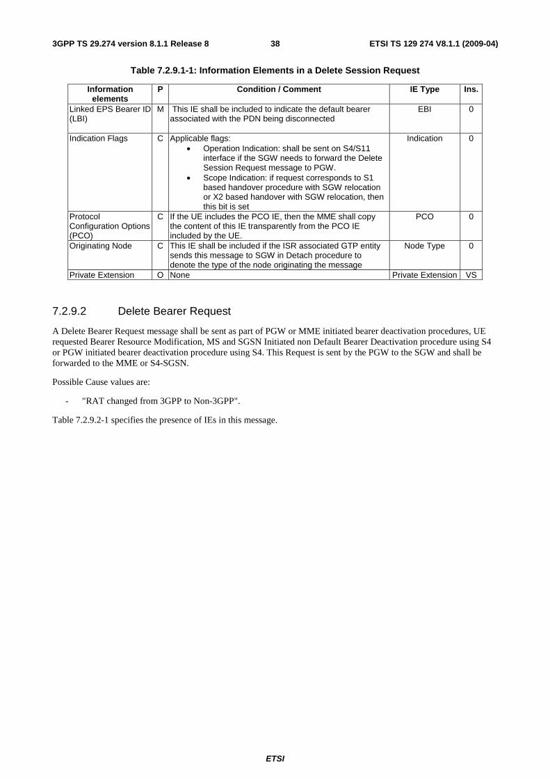
ETSI
ETSI TS 129 274 V8.1.1 (2009-04) 383GPP TS 29.274 version 8.1.1 Release 8
Table 7.2.9.1-1: Information Elements in a Delete Session Request
Information elements
P Condition / Comment IE Type Ins.
Linked EPS Bearer ID (LBI)
M This IE shall be included to indicate the default bearer associated with the PDN being disconnected
EBI 0
Indication Flags C Applicable flags: • Operation Indication: shall be sent on S4/S11
interface if the SGW needs to forward the Delete Session Request message to PGW.
• Scope Indication: if request corresponds to S1 based handover procedure with SGW relocation or X2 based handover with SGW relocation, then this bit is set
Indication 0
Protocol Configuration Options (PCO)
C If the UE includes the PCO IE, then the MME shall copy the content of this IE transparently from the PCO IE included by the UE.
PCO 0
Originating Node C This IE shall be included if the ISR associated GTP entity sends this message to SGW in Detach procedure to denote the type of the node originating the message
Node Type 0
Private Extension O None Private Extension VS
7.2.9.2 Delete Bearer Request
A Delete Bearer Request message shall be sent as part of PGW or MME initiated bearer deactivation procedures, UE requested Bearer Resource Modification, MS and SGSN Initiated non Default Bearer Deactivation procedure using S4 or PGW initiated bearer deactivation procedure using S4. This Request is sent by the PGW to the SGW and shall be forwarded to the MME or S4-SGSN.
Possible Cause values are:
- "RAT changed from 3GPP to Non-3GPP".
Table 7.2.9.2-1 specifies the presence of IEs in this message.
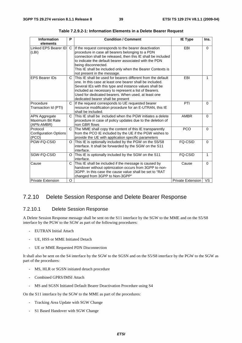
ETSI
ETSI TS 129 274 V8.1.1 (2009-04) 393GPP TS 29.274 version 8.1.1 Release 8
Table 7.2.9.2-1: Information Elements in a Delete Bearer Request
Information elements
P Condition / Comment IE Type Ins.
Linked EPS Bearer ID (LBI)
C If the request corresponds to the bearer deactivation procedure in case all bearers belonging to a PDN connection shall be released, then this IE shall be included to indicate the default bearer associated with the PDN being disconnected. This IE shall be included only when the Bearer Contexts is not present in the message.
EBI 0
EPS Bearer IDs C This IE shall be used for bearers different from the default one. In this case at least one bearer shall be included. Several IEs with this type and instance values shall be included as necessary to represent a list of Bearers. Used for dedicated bearers. When used, at least one dedicated bearer shall be present
EBI 1
Procedure Transaction Id (PTI)
C If the request corresponds to UE requested bearer resource modification procedure for an E-UTRAN, this IE shall be included.
PTI 0
APN Aggregate Maximum Bit Rate (APN-AMBR)
C This IE shall be included when the PGW initiates a delete procedure in case of policy updates due to the deletion of non GBR flows
AMBR 0
Protocol Configuration Options (PCO)
C The MME shall copy the content of this IE transparently from the PCO IE included by the UE if the PGW wishes to provide the UE with application specific parameters
PCO 0
PGW-FQ-CSID O This IE is optionally included by the PGW on the S5/S8 interface. It shall be forwarded by the SGW on the S11 interface.
FQ-CSID 0
SGW-FQ-CSID O This IE is optionally included by the SGW on the S11 interface.
FQ-CSID 1
Cause C This IE shall be included if the message is caused by handover without optimization occurs from 3GPP to non-3GPP. In this case the cause value shall be set to “RAT changed from 3GPP to Non-3GPP"
Cause 0
Private Extension O Private Extension VS
7.2.10 Delete Session Response and Delete Bearer Response
7.2.10.1 Delete Session Response
A Delete Session Response message shall be sent on the S11 interface by the SGW to the MME and on the S5/S8 interface by the PGW to the SGW as part of the following procedures:
- EUTRAN Initial Attach
- UE, HSS or MME Initiated Detach
- UE or MME Requested PDN Disconnection
It shall also be sent on the S4 interface by the SGW to the SGSN and on the S5/S8 interface by the PGW to the SGW as part of the procedures:
- MS, HLR or SGSN initiated detach procedure
- Combined GPRS/IMSI Attach
- MS and SGSN Initiated Default Bearer Deactivation Procedure using S4
On the S11 interface by the SGW to the MME as part of the procedures:
- Tracking Area Update with SGW Change
- S1 Based Handover with SGW Change

ETSI
ETSI TS 129 274 V8.1.1 (2009-04) 403GPP TS 29.274 version 8.1.1 Release 8
- X2 Based Handover with SGW Relocation
- E-UTRAN to UTRAN Iu mode Inter RAT handover with SGW change
- E-UTRAN to GERAN A/Gb mode Inter RAT handover with SGW change
- Inter RAT with SGW change handover cancel
- MME to 3G Gn/Gp SGSN combined hard handover and SRNS relocation procedure
- MME to SGSN Routing Area Update
- E-UTRAN to Gn/Gp SGSN Inter RAT handover
And on the S4 interface by the SGW to the SGSN as part of the procedures:
- Enhanced Serving RNS Relocation with SGW relocation using S4
- Routing Area Update with SGW change
- SGSN to MME Tracking Area Update
- Serving RNS relocation with SGW change
- UTRAN Iu mode to E-UTRAN Inter RAT handover with SGW change
- GERAN A/Gb mode to E-UTRAN Inter RAT handover with SGW change
The sending entity shall include Cause IE in the Delete Session Response message. The IE indicates if the peer has deleted the bearer, or not.
Possible Cause values are:
- "Request accepted".
- "Context not found".
- "Mandatory IE incorrect".
- "Mandatory IE missing".
- "Optional IE incorrect".
- "Invalid message format".
- "Unexpected repeated IE"
Table 7.2.10.1-1 specifies the presence of the IEs in the message.
Table 7.2.10.1-1: Information Elements in a Delete Session Response
Information elements
P Condition / Comment IE Type Ins.
Cause M Cause 0 Recovery C This IE shall be included If contacting the peer for the first
time Recovery 0
Protocol Configuration Options (PCO)
C The MME shall copy the content of this IE transparently from the PCO IE included by the UE if the PGW wishes to provide the UE with application specific parameters
PCO 0
Private Extension O Private Extension VS
7.2.10.2 Delete Bearer Response
The Delete Bearer Response shall be sent as a response of Delete Bearer Request.
Possible Cause values are:

ETSI
ETSI TS 129 274 V8.1.1 (2009-04) 413GPP TS 29.274 version 8.1.1 Release 8
- "Request accepted".
- "Request accepted partially".
- "Request rejected".
- "Context not found".
- "Mandatory IE incorrect".
- "Mandatory IE missing".
- "System failure".
- "Optional IE incorrect".
- "Invalid message format".
- "Unexpected repeated IE".
Table 7.2.10.2-1: Information Elements in Delete Bearer Response
Information elements
P Condition / Comment IE Type Ins.
Cause M Cause 0 Linked EPS Bearer ID (LBI)
C If the response corresponds to the bearer deactivation procedure in case all the bearers associated with the default bearer of a PDN connection shall be released, this IE shall be included to indicate the default bearer associated with the PDN being disconnected.
EBI 0
Bearer Contexts C It shall be used for bearers different from default one. In this case at least one bearer shall be included. Several IEs with this type and instance values shall be included as necessary to represent a list of Bearers. Used for dedicated bearers. When used, at least one dedicated bearer shall be present.
Bearer Context 0
Recovery C This IE shall be included if contacting the peer for the first time
Recovery 0
MME-FQ-CSID O This IE is optionally included by MME the on S11 interface. It shall be forwarded by the SGW on S5/S8 interface.
FQ-CSID 0
SGW-FQ-CSID O This IE is optionally included by the SGW on the S5/S8 interface.
FQ-CSID 1
Private Extension O Private Extension VS
Table 7.2.10.2-2: Bearer Context within Delete Bearer Response
Octet 1 Bearer Context IE Type = 93 (decimal) Octets 2 and 3 Length = n Octet 4 Spare and Instance fields
Information elements
P Condition / Comment IE Type Ins.
EPS Bearer ID M EBI 0 Cause M This IE shall indicate if the bearer handling was successful,
and if not, gives information on the reason. Cause 0
7.2.11 Downlink Data Notification messages
7.2.11.1 Downlink Data Notification
A Downlink Data Notification message shall be sent on the S11 interface by the SGW to the MME as a part of the network triggered service request procedure.

ETSI
ETSI TS 129 274 V8.1.1 (2009-04) 423GPP TS 29.274 version 8.1.1 Release 8
The message shall also be sent on the S4 interface by the SGW to the SGSN as part of Paging with no established user plane on S4, SGW triggered paging with S4.
Table 7.2.11.1-1 specifies the presence of the IEs in the message.
Table 7.2.11.1-1: Information Elements in a Downlink Data Notification
Information elements
P Condition / Comment IE Type Ins.
Private Extension O Private Extension VS
7.2.11.2 Downlink Data Notification Acknowledgement
A Downlink Data Notification Acknowledgement shall be sent from a MME/SGSN to a SGW in response to Downlink Data Notification with an indication of success, or failure when MME/SGSN has reachability or abnormal conditions.
Possible Cause values are:
- "Request accepted".
- "Unable to page UE".
- "Invalid message format".
- "Optional IE incorrect ".
Table 7.2.11.2-1 specifies the presence of the IEs in the message.
Table 7.2.11.2-1: Information Elements in a Downlink Data Notification Acknowledgement
Information elements
P Condition / Comment IE Type Ins.
Cause M Cause 0 Data Notification Delay
C The MME/SGSN shall include an adaptive delay indication to the SGW to delay the number of Data Notification indications, if the rate of Downlink Data Notification event occurence in the MME/SGSN becomes significant (as configured by the operator) and the MME/SGSN's load exceeds an operator configured value.
Delay Value 0
Recovery C This IE shall be included if contacting the peer for the first time
Recovery 0
Private Extension O Private Extension VS
7.2.11.3 Downlink Data Notification Failure Indication
A Downlink Data Notification Failure indication shall be sent from an MME/SGSN to a SGW indicating that the UE did not respond to paging. It shall also be sent in the case that the UE responded to the page with a Service Request but that the MME has rejected the request by sending a Service Reject to the UE because the requested service is not supported.
Possible Cause values are:
- "UE not responding".
- "Service denied".
Table 7.2.11.3-1 specifies the presence of the IEs in the message.

ETSI
ETSI TS 129 274 V8.1.1 (2009-04) 433GPP TS 29.274 version 8.1.1 Release 8
Table 7.2.11.3-1: Information Elements in a Downlink Data Notification Failure Indication
Information elements
P Condition / Comment IE Type Ins.
Cause M Cause 0 Private Extension O Private Extension VS
7.2.12 Delete Indirect Data Forwarding Tunnel Request
The Delete Indirect Data Forwarding Tunnel Request message is sent on the S11 interface by the MME to the SGW as part of the following procedures:
- S1-based handover
- UTRAN Iu mode to E-UTRAN Inter RAT handover
- GERAN A/Gb mode to E-UTRAN Inter RAT handover
This message is also sent on the S4 interface by the SGSN to the SGW as part of the procedure:
- E-UTRAN to UTRAN Iu mode Inter RAT handover
Table 7.2.12-1: Information Element in Delete Indirect Data Forwarding Tunnel Request
Information elements
P Condition / Comment IE Type Ins.
Private Extension O Vendor or operator specific information Private Extension VS
7.2.13 Delete Indirect Data Forwarding Tunnel Response
The Delete Indirect Data Forwarding Tunnel Response message is sent on the S11 interface by the SGW to the MME as part of the following procedures:
- S1-based handover
- UTRAN Iu mode to E-UTRAN Inter RAT handover
- GERAN A/Gb mode to E-UTRAN Inter RAT handover
This message is also sent on the S4 interface by the SGW to the SGSN as part of the procedure:
- E-UTRAN to UTRAN Iu mode Inter RAT handover
Table 7.2.13-1: Information Element in Delete Indirect Data Forwarding Tunnel Response
Information elements
P Condition / Comment IE Type Ins.
Private Extension O Vendor or operator specific information Private Extension VS
7.2.14 Modify Bearer Command and Failure Indication
7.2.14.1 Modify Bearer Command
The Modify Bearer Command shall be sent on the S11 interface by the MME to the SGW and on the S5/S8 interface by the SGW to the PGW as part of the HSS Initiated Subscribed QoS Modification procedure.
It shall also be sent on the S4 interface by the SGSN to the SGW and on the S5/S8 interface by the SGW to the PGW as part of the HSS Initiated subscribed QoS modification.

ETSI
ETSI TS 129 274 V8.1.1 (2009-04) 443GPP TS 29.274 version 8.1.1 Release 8
Table 7.2.14.1-1: Information Elements in a Modify Bearer Command
Information elements
P Condition / Comment IE Type Ins.
APN-Aggregate Maximum Bit Rate (APN-AMBR)
M This IE shall contain the modified APN-AMBR value received by the MME/SGSN from the HSS.
AMBR 0
Bearer Contexts M Several IEs with this type and instance values shall be included as necessary to represent a list of Bearers
Bearer Context 0
Private Extension O Private Extension VS
Table 7.2.14.1-2: Bearer Context within Modify Bearer Command
Octet 1 Bearer Context IE Type = 93 (decimal) Octets 2 and 3 Length = n Octet 4 Spare and Instance fields
Information elements
P Condition / Comment IE Type Ins.
EPS Bearer ID M This IE shall contain the bearer that has been modified. EBI 0 Bearer Level QoS C Mandatory if other parameters than the APN-AMBR have
been changed Bearer QoS 0
7.2.14.2 Modify Bearer Failure Indication
The Modify Bearer Failure Indication shall be sent on the S5/S8 interface by the PGW to the SGW and on the S11 interface by the SGW to the MME as part of failure of HSS Initiated Subscribed QoS Modification procedure.
It shall also be sent on the S5/S8 interface by the PGW to the SGW and on the S4 interface by the SGW to the SGSN as part of failure of HSS Initiated subscribed QoS modification.
Cause IE indicates that an EPS bearer has not been updated in the PGW.
Possible Cause values are:
- "Context not found"
- "No resources available".
- "No memory available".
- "System failure".
- "Mandatory IE incorrect".
- "Mandatory IE missing".
- "Optional IE incorrect".
- "Invalid message format".
- "Unexpected repeated IE"
Table 7.2.14.2-1: Information Elements in a Modify Bearer Failure Indication
Information elements
P Condition / Comment IE Type Ins.
Cause M Cause 0 Bearer Context M Several IEs with this type and instance values shall be
included as necessary to represent a list of Bearers Bearer Context 0
Recovery C This IE shall be included if contacting the peer for the first time
Recovery 0
Private Extension O Private Extension VS

ETSI
ETSI TS 129 274 V8.1.1 (2009-04) 453GPP TS 29.274 version 8.1.1 Release 8
Table 7.2.14.2-2: Bearer Context within Modify Bearer Failure Indication
Octet 1 Bearer Context IE Type = 93 (decimal) Octets 2 and 3 Length = n Octet 4 Spare and Instance fields
Information elements
P Condition / Comment IE Type Ins.
EPS Bearer ID M This IE shall contain the bearers that have failed. EBI 0 Cause M This IE shall Indicate if the bearer handling was successful,
and if not, gives information on the reason. Cause 0
7.2.15 Update Bearer Request
For GTP based S5/S8, the Update Bearer Request shall be sent by the PGW to the SGW and forwarded to the MME as part of the following procedures:
- PGW Initiated Bearer Modification with Bearer QoS Update
- HSS Initiated Subscribed QoS Modification
- PGW Initiated Bearer Modification without Bearer QoS Update
- UE Request Bearer Resource Modification procedure
The message shall also be sent on the S5/S8 interface by the PGW to the SGW and on the S4 interface by the SGW to the SGSN as part of the following procedures:
- PGW Initiated EPS Bearer Modification
- Execution part of MS-Initiated EPS Bearer Modification
- SGSN-Initiated EPS Bearer Modification Procedure using S4
For PMIP based S5/S8, the Update Bearer Request shall be sent on the S11 interface by the SGW to the MME and on the S4 interface by the SGW to the SGSN.
Table 7.2.15-1 specifies the presence requirements and the conditions of the IEs in the message.

ETSI
ETSI TS 129 274 V8.1.1 (2009-04) 463GPP TS 29.274 version 8.1.1 Release 8
Table 7.2.15-1: Information Elements in an Update Bearer Request
Information elements
P Condition / Comment IE Type Ins.
IMSI M IMSI 0 Bearer Contexts M This IE shall contain contexts related to bearers that need
QoS/TFT modification. Several IEs with this type and instance values shall be included as necessary to represent a list of Bearers.
Bearer Context 0
Procedure Transaction Id (PTI)
C If the request corresponds to UE requested bearer resource modification procedure for an E-UTRAN or MS initiated EPS bearer modification procedure, this IE shall be included. PTI shall be the same as the one used in the corresponding Bearer Resource Command
PTI 0
Protocol Configuration Options (PCO)
C PGW shall include Protocol Configuration Options (PCO) IE, if available.
PCO 0
Aggregate Maximum Bit Rate (APN-AMBR)
M APN-AMBR AMBR 0
Trace Information C Trace Reference, Trace Type, Trigger Id, OMC Identity. Included if SGW and/or PGW is activated.
Trace Information 0
Change Reporting Action
C This IE shall be included with the appropriate Action field If the location Change Reporting mechanism is to be started or stopped for this subscriber in the SGSN/MME.
Change Reporting Action
0
PGW-FQ-CSID O Optionally included by PGW on S5/S8. Shall be forwarded by SGW on S11.
FQ-CSID 0
SGW-FQ-CSID O Optionally included by SGW on S11. FQ-CSID 1 Private Extension O Private Extension VS
Table 7.2.15-2: Bearer Context within Update Bearer Request
Octet 1 Bearer Context IE Type = 93 (decimal) Octets 2 and 3 Length = n Octet 4 Spare and Instance fields
Information elements
P Condition / Comment IE Type Ins.
EPS Bearer ID M EBI 0 UL TFT O This IE shall be included if message relates to Bearer
Modification and TFT change or if PMIP based S5/S8 Bearer TFT 0
DL TFT O PMIP based S5/S8 only Bearer TFT 1 Bearer Level QoS C This IE shall be included if QoS modification is requested Bearer QoS 0 Charging Characteristics
C This IE shall be included according to TS 32.251. Charging Characteristics
0
Bearer Flags O Applicable flags: PPC (Prohibit Payload Compression)
Bearer Flags 0
7.2.16 Update Bearer Response
An Update Bearer Response shall be sent from a MME/SGSN to a SGW and forwarded to the PGW as a response to an Update Bearer Request message.
Table 7.2.16-1 specifies the presence requirements and the conditions of the IEs in the message.
Cause IE indicates if an EPS bearer has been modifed in the MME/SGSN or not. The EPS Bearer has not been modified in the MME if the Cause IE value differs from "Request accepted" or "Request accepted partially". Possible Cause values are:
- "Request accepted".
- "Request accepted partially"
- "Request rejected"

ETSI
ETSI TS 129 274 V8.1.1 (2009-04) 473GPP TS 29.274 version 8.1.1 Release 8
- "Context not found"
- "Mandatory IE incorrect".
- "Mandatory IE missing".
- "System failure".
- "Semantic error in the TFT operation".
- "Syntactic error in the TFT operation".
- "Semantic errors in packet filter(s)".
- "Syntactic errors in packet filter(s)".
- "Optional IE incorrect".
- "Invalid message format".
- "Unexpected repeated IE"
Table 7.2.16-1: Information Elements in an Update Bearer Response
Information elements
P Condition / Comment IE Type Ins.
Cause M Cause 0 Bearer Contexts M This IE shall contain contexts related to bearers for which
QoS/TFT modification was requested. Several IEs with this type and instance values shall be included as necessary to represent a list of Bearers
Bearer Context 0
Protocol Configuration Options (PCO)
C MME/SGSN shall include PCO IE if such information was received from the PGW. This IE shall be included if the Cause IE contains the value "Request accepted".
PCO 0
Recovery C This IE shall be included if contacting the peer for the first time
Recovery 0
MME-FQ-CSID O Optionally included by MME on S11. Shall be forwarded by SGW on S5/S8.
FQ-CSID 0
SGW-FQ-CSID O Optionally included by SGW on S11. FQ-CSID 1 Private Extension O Private Extension VS
Table 7.2.16-2: Bearer Context within Update Bearer Response
Octet 1 Bearer Context IE Type = 93 (decimal) Octets 2 and 3 Length = n Octet 4 Spare and Instance fields
Information elements
P Condition / Comment IE Type Ins.
EPS Bearer ID M EBI 0 Cause M This IE Indicates if the bearer handling was successful,
and if not, gives information on the reason. Cause 0
7.2.17 Delete Bearer Command and Failure Indication
7.2.17.1 Delete Bearer Command
A Delete Bearer Command message shall be sent on the S11 interface by the MME to the SGW and on the S5/S8 interface by the SGW to the PGW as a part of the eNodeB requested bearer release or MME-Initiated Dedicated Bearer Deactivation procedure.
The message shall also be sent on the S4 interface by the SGSN to the SGW and on the S5/S8 interface by the SGW to the PGW as part of the MS and SGSN Initiated non Default Bearer Deactivation procedure using S4.

ETSI
ETSI TS 129 274 V8.1.1 (2009-04) 483GPP TS 29.274 version 8.1.1 Release 8
Table 7.2.17.1-1: Information Elements in Delete Bearer Command
Information elements
P Condition / Comment IE Type Ins.
Bearer Contexts M This IE shall be used to indicate dedicated bearers. When used, at least one dedicated bearer shall be present. Several IEs with this type and instance values shall be included as necessary to represent a list of Bearers
Bearer Context 0
Private Extension O Private Extension VS
Table 7.2.17.1-2: Bearer Context within Delete Bearer Command
Octet 1 Bearer Context IE Type = 93 (decimal) Octets 2 and 3 Length = n Octet 4 Spare and Instance fields
Information elements
P Condition / Comment IE Type Ins.
EPS Bearer ID M EBI 0 Protocol Configuration Option (PCO)
O None PCO 0
7.2.17.2 Delete Bearer Failure Indication
A Delete Bearer Failure Indication shall be sent on the S5/S8 interface by the PGW to the SGW and on the S11 interface by the SGW to the MME as part of failure of eNodeB requested bearer release or MME Initiated Dedicated Bearer Deactivation procedure.
The message shall also be sent on the S5/S8 interface by the PGW to the SGW and on the S4 interface by the SGW to the SGSN as part of the MS and SGSN Initiated non Default Bearer Deactivation procedure using S4.
Cause IE indicates that an EPS bearer has not been deleted in the PGW.
Possible Cause values are:
- "Context not found"
- "Mandatory IE incorrect".
- "Mandatory IE missing".
- "System failure".
- "Optional IE incorrect".
- "Invalid message format".
- "Unexpected repeated IE"
Table 7.2.17.2-1: Information Elements in a Delete Bearer Failure Indication
Information elements
P Condition / Comment IE Type Ins.
Cause M Cause 0 Bearer Context M This IE shall contain the list of failed bearers. Bearer Context 0 Recovery C This IE shall be included If contacting the peer for the first
time. Recovery 0
Private Extension O Private Extension VS
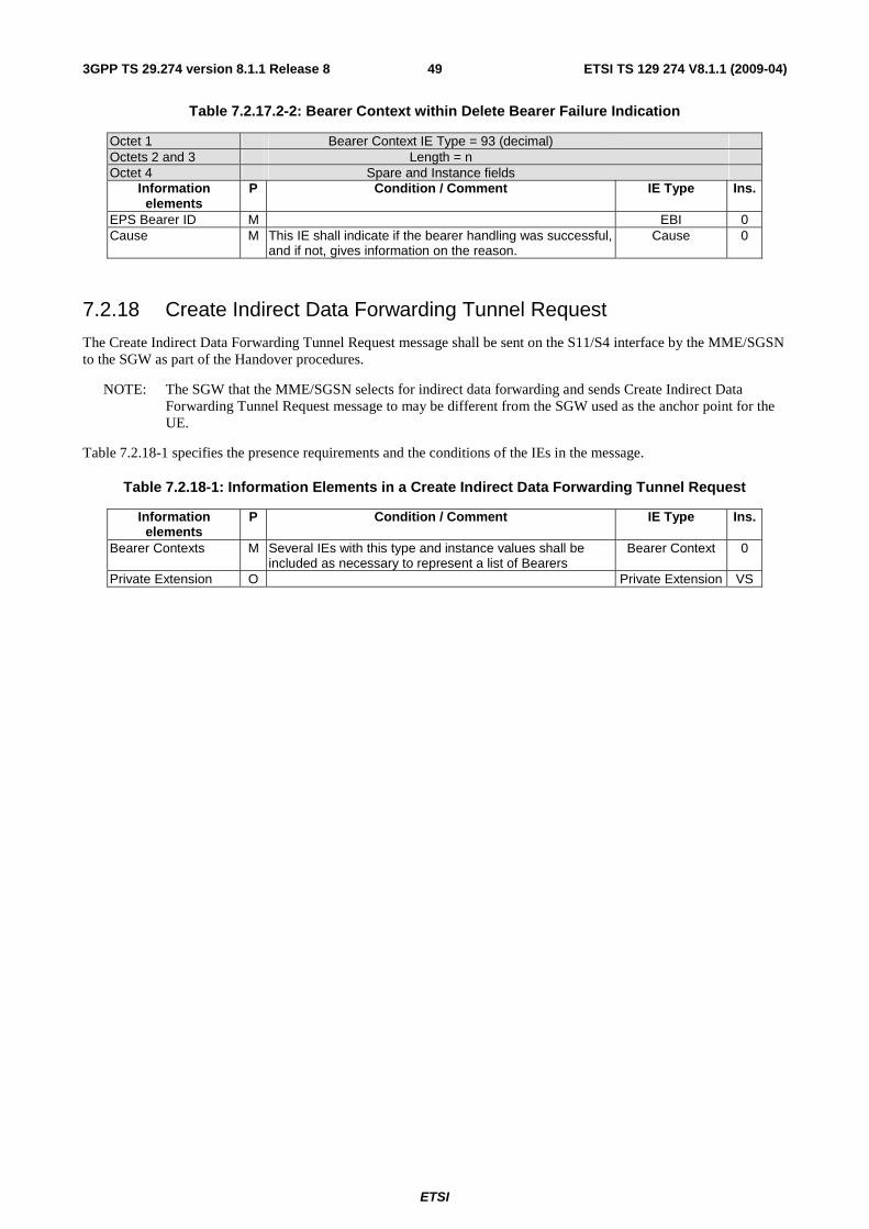
ETSI
ETSI TS 129 274 V8.1.1 (2009-04) 493GPP TS 29.274 version 8.1.1 Release 8
Table 7.2.17.2-2: Bearer Context within Delete Bearer Failure Indication
Octet 1 Bearer Context IE Type = 93 (decimal) Octets 2 and 3 Length = n Octet 4 Spare and Instance fields
Information elements
P Condition / Comment IE Type Ins.
EPS Bearer ID M EBI 0 Cause M This IE shall indicate if the bearer handling was successful,
and if not, gives information on the reason. Cause 0
7.2.18 Create Indirect Data Forwarding Tunnel Request
The Create Indirect Data Forwarding Tunnel Request message shall be sent on the S11/S4 interface by the MME/SGSN to the SGW as part of the Handover procedures.
NOTE: The SGW that the MME/SGSN selects for indirect data forwarding and sends Create Indirect Data Forwarding Tunnel Request message to may be different from the SGW used as the anchor point for the UE.
Table 7.2.18-1 specifies the presence requirements and the conditions of the IEs in the message.
Table 7.2.18-1: Information Elements in a Create Indirect Data Forwarding Tunnel Request
Information elements
P Condition / Comment IE Type Ins.
Bearer Contexts M Several IEs with this type and instance values shall be included as necessary to represent a list of Bearers
Bearer Context 0
Private Extension O Private Extension VS

ETSI
ETSI TS 129 274 V8.1.1 (2009-04) 503GPP TS 29.274 version 8.1.1 Release 8
Table 7.2.18-2: Bearer Context within Create Indirect Data Forwarding Tunnel Request
Octet 1 Bearer Context IE Type = 93 (decimal) Octets 2 and 3 Length = n Octet 4 Spare and Instance fields
Information elements
P Condition / Comment IE Type Ins.
EPS Bearer ID M EBI 0 eNodeB F-TEID for data forwarding
C Target eNodeB F-TEID. This IE shall be present in the message sent from the target MME to the target SGW, or shall be included in the message sent from the source SGSN/MME to the source SGW if the eNodeB F-TEID for data forwarding is included in the Forward Relocation Response message.
F-TEID 0
SGW F-TEID for data forwarding
C Target SGW F-TEID This IE shall be present in the message sent from the source MME/SGSN to the source SGW if SGW F-TEID for data forwarding is included in the Forward Relocation Response message. This F-TEID is assigned by the SGW that the target MME/SGSN selects for indirect data forwarding.
F-TEID 1
SGSN F-TEID for data forwarding
C Target SGSN F-TEID This IE shall be present in the message sent from the target SGSN to the target SGW in E-UTRAN to GERAN inter RAT handover with SGW relocation procedure, or shall be included in the message sent from the source MME to the source SGW if the SGSN F-TEID for data forwarding is included in the Forwarding Relocation Response message.
F-TEID 2
RNC F-TEID for data forwarding
C Target RNC F-TEID This IE shall be present in the message sent from the target SGSN to the target SGW in E-UTRAN to UTRAN inter RAT handover with SGW relocation procedure, or shall be included in the message sent from the source MME to the source SGW if the RNC F-TEID for data forwarding is included in the Forwarding Relocation Response message.
F-TEID 3
7.2.19 Create Indirect Data Forwarding Tunnel Response
A Create Indirect Data Forwarding Tunnel Response message shall be sent by the SGW to the MME/SGSN as a response to a Create Indirect Data Forwarding Tunnel Request message.
Table 7.2.19-1 specifies the presence requirements and the conditions of the IEs in the message.
The Cause value indicates if the Indirect Data Forwarding Tunnels has been created in the SGW or not. Indirect Data Forwarding Tunnels have not been created in the SGW if the Cause differs from "Request accepted". Possible Cause values are:
- "Request Accepted".
- "No resources available".
- "System failure".
- "Mandatory IE incorrect".
- "Mandatory IE missing".
- "Optional IE incorrect".
- "Invalid message format".
Only the Cause IE shall be included in the response if the Cause IE contains another value than "Request accepted".

ETSI
ETSI TS 129 274 V8.1.1 (2009-04) 513GPP TS 29.274 version 8.1.1 Release 8
Table 7.2.19-1: Information Elements in a Create Indirect Data Forwarding Tunnel Response
Information elements
P Condition / Comment IE Type Ins.
Cause M Cause 0 Bearer Contexts M Several IEs with this type and instance values shall be
included as necessary to represent a list of Bearers Bearer Context 0
Private Extension O Private Extension VS
Table 7.2.19-2: Bearer Context within Create Indirect Data Forwarding Tunnel Response
Octet 1 Bearer Context IE Type = 93 (decimal) Octets 2 and 3 Length = n Octet 4 Spare and Instance fields
Information elements
P Condition / Comment IE Type Ins.
EPS Bearer ID M EBI 0 Cause M This IE shall indicate if the tunnel setup was successful,
and if not, gives information on the reason. Cause 0
S1-U SGW F-TEID C This IE shall be included in the response sent from the source SGW to the source MME.
F-TEID 0
S12 SGW F-TEID C S12 usage only. This IE shall be included in the response sent from the source SGW to the source SGSN.
F-TEID 1
S4-U SGW F-TEID C S4-U usage only. This IE shall be included in the response sent from the source SGW to the source SGSN.
F-TEID 2
SGW F-TEID for data forwarding
C This IE shall be included in the response message sent from the target SGW to the target MME/SGSN.
F-TEID 3
7.2.20 Update Bearer Complete
The Update Bearer Complete message is sent on S4 by the SGW to the SGSN as part of the MS or SGSN initiated modification procedure.
Table 7.2.20-1 specifies the presence of the IEs in the message.
Table 7.2.20-1: Information Elements in an Update Bearer Complete
Information elements
P Condition / Comment IE Type Ins.
Cause M None Cause 0 Bearer Contexts M Several IEs with this type and instance values shall be
included as necessary to represent a list of Bearers Bearer Context 0
Private Extension O None Private Extension VS
Table 7.2.20-2: Bearer Context within Update Bearer Complete
Octet 1 Bearer Context IE Type = 93 (decimal) Octets 2 and 3 Length = n Octet 4 Spare and Instance fields
Information elements
P Condition / Comment IE Type Ins.
EPS Bearer ID M None EBI 0 Cause M Indicates if the bearer handling was successful, and if not,
gives information on the reason. Cause 0

ETSI
ETSI TS 129 274 V8.1.1 (2009-04) 523GPP TS 29.274 version 8.1.1 Release 8
7.2.21 Release Access Bearers Request
The Release Access Bearers Request message shall sent on the S11 interface by the MME to the SGW as part of the S1 release procedure.
The message shall also be sent on the S4 interface by the SGSN to the SGW as part of the procedures:
- RAB release using S4
- Iu Release using S4
Table 7.2.21-1: Information Element in Release Access Bearers Request
Information elements
P Condition / Comment IE Type Ins.
List of RABs C Shall be present on S4 when this message is used to release a subset of all active RABs according to the RAB release procedure using S4. Several IEs with this type and instance values shall be included as necessary to represent a list of RABs to be released.
EBI 0
Private Extension O Vendor or operator specific information Private Extension VS
7.2.22 Release Access Bearers Response
The Release Access Bearers Response message is sent on the S11 interface by the SGW to the MME as part of the S1 release procedure.
The message shall also be sent on the S4 interface by the SGW to the SGSN as part of the procedures:
- RAB release using S4
- Iu Release using S4
Table 7.2.22-1: Information Element in Release Access Bearers Response
Information elements
P Condition / Comment IE Type Ins.
Cause M None Cause 0 Private Extension O Vendor or operator specific information Private Extension VS
7.2.23 Stop Paging Indication
A Stop Paging Indication message shall be sent on the S11/S4 interface by the SGW to the MME/SGSN as a part of the network triggered service request procedure.
Table 7.2.23-1 specifies the presence of the IEs in the message.
Table 7.2.23-1: Information Elements in a Stop Paging Indication
Information elements
P Condition / Comment IE Type Ins.
Private Extension O Private Extension VS

ETSI
ETSI TS 129 274 V8.1.1 (2009-04) 533GPP TS 29.274 version 8.1.1 Release 8
7.3 Mobility Management Messages
7.3.1 Forward Relocation Request
A Forward Relocation Request message shall be sent from the source MME to the target MME over S10 interface as part of S1-based handover relocation procedure from the source MME to the target SGSN, or from the source SGSN to the target MME over S3 interface as part of Inter RAT handover and combined hard handover and SRNS relocation procedures, or from source SGSN to the target SGSN over S16 interface as part of SRNS Relocation and PS handover procedures.
Table 7.3.1-1 specifies the presence requirements and conditions of the IEs in the message.

ETSI
ETSI TS 129 274 V8.1.1 (2009-04) 543GPP TS 29.274 version 8.1.1 Release 8
Table 7.3.1-1: Information Elements in a Forward Relocation Request
Information elements
P Condition / Comment IE Type Ins.
IMSI M IMSI 0 Sender's F-TEID for Control Plane
M This IE specifies the address and the tunnel for control plane message which is chosen by the source MME/SGSN.
F-TEID 0
MME/SGSN UE EPS PDN Connections
M Several IEs with this type and instance values shall be included as necessary to represent a list of PDN Connections
PDN Connection 0
SGW S11/S4 IP Address and TEID for Control Plane
M F-TEID 1
SGW node name C This IE shall be included if the source MME or SGSN has the source SGW FQDN.
FQDN 0
MME/SGSN UE MM Context
M None MM Context 0
Indication C This IE shall be included if either one of the DFI flag and ISRSI flag is set. DFI flag is set if direct forwarding is supported. DFI flag shall not be set if the message is used for SRNS relocation procedure. ISRSI flag is set if the source MME/SGSN is capable to establish ISR for the UE or if the ISR is activated, the source MME/SGSN then indicate the target SGSN/MME to maintain ISR for the UE in the inter RAT handover procedures.
Indication 0
E-UTRAN Transparent Container
C This IE shall be included if the message is used for UTRAN/GERAN to E-UTRAN inter RAT handover procedure, intra RAT handover procedure and 3G SGSN to MME combined hard handover and SRNS relocation procedure.
F-Container 0
UTRAN Transparent Container
C This IE shall be included if the message is used for PS handover to UTRAN Iu mode procedures, SRNS relocation procedure and E-TURAN to UTRAN inter RAT handover procedure.
F-Container 1
Target Identification C This IE shall be included if the message is used for SRNS relocation procedure and handover to UTRAN/E-UTRAN procedures.
Target Identification
0
HRPD access node S101 IP address
C This IE shall be included only if the HRPD pre registration was performed at the source MME
IP-Address 0
1xIWS S102 IP address
C This IE shall be included only if the 1xRTT CS fallback pre registration was performed at the source MME
IP-Address 0
RAN Cause C This IE is the information from the source eNodeB, the source MME shall include this IE in the message.
F-Cause 0
RANAP Cause C This IE is the information from the source RNC, the source SGSN shall include this IE in the message.
F-Cause 1
BSS Container C This IE shall be included if the message is used for PS handover to GERAN A/Gb mode and E-UTRAN to GERAN A/Gb mode inter RAT handover procedure.
F-Container 0
Source Identification C This IE shall be included if the message is used for PS handover to GERAN A/Gb mode and E-UTRAN to GERAN A/Gb mode inter RAT handover procedure.
Source Identification
0
BSSGP Cause C This IE is the information from source BSS, the source SGSN shall include this IE in the message.
F-Cause 2
Selected PLMN ID O The Selected PLMN ID IE indicates the core network operator selected for the UE in a shared network. The old SGSN shall include this IE if the selected PLMN identity is available.
Selected PLMN ID
0
Recovery C If contacting the peer for the first time Recovery 0 Trace Information C This IE shall be included when session trace is active for
this IMSI/IMEI. Trace Information 0
Private Extension O Private Extension VS
The PDN Connection grouped IE shall be coded as depicted in Table 7.3.1-2.

ETSI
ETSI TS 129 274 V8.1.1 (2009-04) 553GPP TS 29.274 version 8.1.1 Release 8
Table 7.3.1-2: MME/SGSN UE EPS PDN Connections within Forward Relocation Request
Octet 1 PDN Connection IE Type = 109 (decimal) Octets 2 and 3 Length = n Octet 4 Spare and Instance fields
Information elements
P Condition / Comment IE Type Instance
APN M APN 0 IPv4 Address C This IE shall not be included if no IPv4 Address is
assigned. IP Address 0
IPv6 Address C This IE shall not be included if no IPv6 Address is assigned.
IP Address 1
PGW S5/S8 IP Address and TEID for Control Plane
C This IE shall only be included for GTP based S5/S8 F-TEID 0
PGW node name C This IE shall be included if the source MME or SGSN has the PGW FQDN.
FQDN 0
Bearer Contexts C Several IEs with this type and instance values may be included as necessary to represent a list of Bearers.
Bearer Context
0
Aggregate Maximum Bit Rate (APN-AMBR)
C This IE shall be included if the dynamic APN-AMBR is available on the source MME/SGSN for this PDN connection.
AMBR 0
The Bearer Context grouped IE shall be coded as depicted in Table 7.3.1-3.
Table 7.3.1-3: Bearer Context within MME/SGSN UE EPS PDN Connections within Forward Relocation Request
Octet 1 Bearer Context IE Type = 93 Octets 2 and 3 Length = n Octet 4 Spare and Instance fields
Information elements
P Condition / Comment IE Type Instance
EPS Bearer ID M EBI 0 UL TFT C This IE shall be present if an Uplink TFT is defined for this
bearer. Bearer TFT 0
DL TFT C This IE shall be present if a Downlink TFT is defined for this bearer.
Bearer TFT 1
SGW S1/S4/S12 IP Address and TEID for user plane
M F-TEID 0
PGW S5/S8 IP Address and TEID for user plane
C This IE shall be present for GTP based S5/S8 F-TEID 1
Bearer Level QoS M Bearer Level QoS
0
Charging characteristics
M Charging characterist
ics
0
Container O Packet Flow ID, Radio Priority, SAPI, PS Handover XID Parameters may be included
F-Container
0
7.3.2 Forward Relocation Response
A Forward Relocation Response message shall be sent as a response to Forward Relocation Request during S1-based handover procedure, Inter RAT handover procedures, SRNS Relocation procedure and PS handover procedures.
Table 7.3.2-1 specifies the presence requirements and conditions of the IEs in the message.
Cause IE indicates if the relocation has been accepted, or not. The relocation has not been accepted by the target MME/SGSN if the Cause IE value differs from "Request accepted". Possible Cause values are:
- "Request accepted".

ETSI
ETSI TS 129 274 V8.1.1 (2009-04) 563GPP TS 29.274 version 8.1.1 Release 8
- "System failure".
- "Mandatory IE incorrect".
- "Mandatory IE missing".
- "Optional IE incorrect".
- "No resources available".
- "Invalid message format".
- "Relocation failure".
Table 7.3.2-1: Information Elements in a Forward Relocation Response
Information elements
P Condition / Comment IE Type Ins.
Cause M Cause 0 Sender's F-TEID for Control Plane
C If the Cause IE contains the value "Request accepted", the target MME/SGSN shall include this IE in Forward Relocation Response message.
F-TEID 0
Indication C This IE shall be included if the target MME/SGSN has selected a new SGW. This IE shall not be included if the message is used for SRNS relocation procedure. SGWCI flag is set to indicate Serving GW change.
Indication 0
List of Set-up Bearers C The list of set-up Bearers IE contains the EPS bearer Identifiers of the Bearers that were successfully allocated in the target system during a handover procedure. This IE shall be included if the Cause IE contains the value "Request accepted". Several IEs with this type and instance values shall be included as necessary to represent a list of Bearers.
Bearer Context 0
List of Set-up RABs C The list of set-up RABs IE contains the RAB Identifiers of the RABs that were successfully allocated in the target system. This IE shall be included if the Cause IE contains the value "Request accepted". Several IEs with this type and instance values shall be included as necessary to represent a list of Bearers.
Bearer Context 1
List of Set-up PFCs O The list of set-up PFCs IE contains the Packet Flow Identifies of the PFCs that were successfully allocated in the target system during a PS handover to/from GERAN or inter RAT handover to/from GERAN. If the Cause IE contains the value "Request accepted", this IE is included.
Bearer Context 2
eNodeB Cause
C If the Cause IE contains the value "Request accepted", this IE is mandatory if cause value is contained in S1-AP message.
F-Cause 0
RANAP Cause C If the Cause IE contains the value "Request accepted", this IE is mandatory if cause value is contained in RANAP message.
F-Cause 1
E-UTRAN Transparent Container
O This IE contains the radio-related and core network information for handover to E-UTRAN. If the Cause IE contains the value "Request accepted", this IE is included.
F-Container 0
UTRAN Transparent Container
O This IE contains the radio-related and core network information for handover to UTRAN. If the Cause IE contains the value "Request accepted", this IE is included.
F-Container 1
BSS Container O This IE contains the radio-related and core network information for handover to GERAN. If the Cause IE contains the value "Request accepted", this IE is included.
F-Container 2
BSSGP Cause O For handover to GERAN, if a cause value is received from the Target BSC, the BSSGP Cause IE shall be included and shall be sent to the cause value received from the target BSC.
F-Cause 2
Private Extension O None Private Extension VS
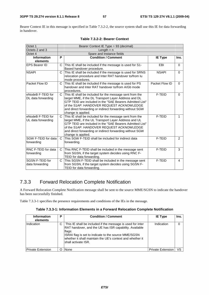
ETSI
ETSI TS 129 274 V8.1.1 (2009-04) 573GPP TS 29.274 version 8.1.1 Release 8
Bearer Context IE in this message is specified in Table 7.3.2-2, the source system shall use this IE for data forwarding in handover.
Table 7.3.2-2: Bearer Context
Octet 1 Bearer Context IE Type = 93 (decimal) Octets 2 and 3 Length = n Octet 4 Spare and Instance fields
Information elements
P Condition / Comment IE Type Ins.
EPS Bearer ID C This IE shall be included if the message is used for S1-Based handover procedure.
EBI 0
NSAPI C This IE shall be included if the message is used for SRNS relocation procedure and Inter RAT handover to/from Iu mode procedures.
NSAPI 0
Packet Flow ID C This IE shall be included if the message is used for PS handover and Inter RAT handover to/from A/Gb mode procedures.
Packet Flow ID 0
eNodeB F-TEID for DL data forwarding
C This IE shall be included for the message sent from the target MME, if the DL Transport Layer Address and DL GTP TEID are included in the "SAE Bearers Admitted List" of the S1AP: HANDOVER REQUEST ACKNOWLEDGE and direct forwarding or indirect forwarding without SGW change is applied.
F-TEID 0
eNodeB F-TEID for UL data forwarding
C This IE shall be included for the message sent from the target MME, if the UL Transport Layer Address and UL GTP TEID are included in the "SAE Bearers Admitted List" of the S1AP: HANDOVER REQUEST ACKNOWLEDGE and direct forwarding or indirect forwarding without SGW change is applied.
F-TEID 1
SGW F-TEID for data forwarding
C This SGW F-TEID shall be included for indirect data forwarding.
F-TEID 2
RNC F-TEID for data forwarding
C This RNC F-TEID shall be included in the message sent from SGSN, if the target system decides using RNC F-TEID for data forwarding.
F-TEID 3
SGSN F-TEID for data forwarding
C This SGSN F-TEID shall be included in the message sent from SGSN, if the target system decides using SGSN F-TEID for data forwarding.
F-TEID 4
7.3.3 Forward Relocation Complete Notification
A Forward Relocation Complete Notification message shall be sent to the source MME/SGSN to indicate the handover has been successfully finished.
Table 7.3.3-1 specifies the presence requirements and conditions of the IEs in the message.
Table 7.3.3-1: Information Elements in a Forward Relocation Complete Notification
Information elements
P Condition / Comment IE Type Ins.
Indication C This IE shall be included if the message is used for inter RAT handover, and the UE has ISR capability. Available flags: ISRAI flag is set to indicate to the source MME/SGSN whether it shall maintain the UE's context and whether it shall activate ISR.
Indication 0
Private Extension O None Private Extension VS

ETSI
ETSI TS 129 274 V8.1.1 (2009-04) 583GPP TS 29.274 version 8.1.1 Release 8
7.3.4 Forward Relocation Complete Acknowledge
A Forward Relocation Complete Acknowledge message shall be sent as a response to Forward Relocation Complete Notification during inter eNodeB handover with MME relocation procedure.
Table 7.3.4-1 specifies the presence requirements and conditions of the IEs in the message.
Table 7.3.4-1: Information Elements in a Forward Relocation Complete Acknowledge
Information elements
P Condition / Comment IE Type Ins.
Cause M None Cause 0 Recovery O None Recovery 0 Private Extension O None Private Extension VS
7.3.5 Context Request
The new MME/SGSN shall send the Context Request message to the old MME/SGSN on S3/S16/S10 interface as a part of TAU/RAU procedure to get the MM and EPS bearer Contexts for the UE.
If the sending node is a MME, it shall include in the Context Request message:
- the GUTI IE and Complete TAU Request Message IE if the GUTI received from UE indicates the old node is a MME.
- the RAI IE, P-TMSI IE and P-TMSI Signature IE if the GUTI received from UE indicates the old node is an SGSN.
Editor's note: It is FFS if other means than GUTI could be needed to identify the old nodes.
If the sending node is an SGSN, it shall include RAI IE, P-TMSI IE and P-TMSI Signature IE in the Context Request message.
The new MME differentiates the type of the old node from the most significant bit of the MME group id in GUTI. The value 0 indicates that the old node is an SGSN, the GUTI shall be mapped to RAI and P-TMSI by the new MME; and the value 1 indicates the old node is a MME, the new MME include GUTI IE and Complete TAU Request Message IE in the Context Request message. The Mapping between temporary and area identities is defined in 3GPP TS 23.003 [2].
The GUTI IE shall not coexist with any of the RAI IE, P-TMSI IE and P-TMSI Signature IE in a Context Request message. If this occurs, the receiving node shall return a corresponding cause value in the response message.
Table 7.3.5-1 specifies the presence requirements and conditions of the IEs in the message.

ETSI
ETSI TS 129 274 V8.1.1 (2009-04) 593GPP TS 29.274 version 8.1.1 Release 8
Table 7.3.5-1: Information Elements in a Context Request
Information elements
P Condition / Comment IE Type Ins.
IMSI C IMSI shall be included if the MS Validated value indicates "YES".
IMSI 0
GUTI C The New MME shall include this IE over S10 interface. GUTI 0 Routeing Area Identity(RAI)
C This IE shall be included over S3/S16 interface, if the GUTI indicates the old node is an SGSN, the new MME maps this IE from GUTI.
ULI for RAI 0
Packet TMSI(P-TMSI) C This IE shall be included over S3/S16 interface, if the GUTI indicates the old node is an SGSN, the new MME maps this IE from GUTI.
P-TMSI 0
P-TMSI Signature C This IE shall be included over S3/S16 interface, if the GUTI indicates the old node is an SGSN, the new MME maps this IE from GUTI.
P-TMSI Signature 0
Complete TAU request message
C The new MME shall include this IE, and the old MME may use this IE for integrity check.
Complete Request Message
0
S3/S16/S10 Address and TEID for Control Plane
C This IE specifies the address and the tunnel for control plane message which is chosen by the new MME/SGSN.
F-TEID 0
UDP Source Port Number
C If an SGSN within the same SGSN pool as the old SGSN receives this message, the SGSN shall include the UDP Source Port number of the received message in this optional parameter if this IE is not present and relay the message to the old SGSN. The old SGSN shall use this UDP port as the UDP destination port of the Context Response message.
Port Number 0
RAT Type C The RAT Type indicates the Radio Access Technology which is used in the new system.
RAT Type 0
HRPD access node S101 IP address
C This IE shall be included only if the HRPD pre registration was performed at the old MME
IP-Address 0
1xIWS S102 IP address
C This IE shall be included only if the 1xRTT CS fallback pre registration was performed at the old MME
IP-Address 0
MS Validated O The MS Validated indicates that the new system has successfully authenticated the UE, IMSI shall be included if the MS Validated value indicates "YES".
MS Validated 0
Hop Counter O If an SGSN within the same SGSN pool with the old SGSN receives this message, the SGSN shall decrement the Hop Counter if this IE is present in the received message; otherwise may include a Hop Counter with a value of max-1, and relay the message to the old SGSN.
Hop Counter 0
Private Extension O Private Extension VS
7.3.6 Context Response
A Context Response message shall be sent as a response to a previous Context Request message during TAU/RAU procedure.
Possible Cause values are:
- "Request Accepted"
- "IMSI not known"
- "System failure"
- "Mandatory IE incorrect"
- "Mandatory IE missing"
- "Optional IE incorrect"
- "Invalid message format"
- "P-TMSI Signature mismatch"

ETSI
ETSI TS 129 274 V8.1.1 (2009-04) 603GPP TS 29.274 version 8.1.1 Release 8
- "User authentication failed"
Table 7.3.6-1 specifies the presence requirements and conditions of the IEs in the message.
Table 7.3.6-1: Information Elements in a Context Response
Information elements
P Condition / Comment IE Type Ins.
Cause M Cause 0 IMSI C IMSI 0 MME/SGSN UE MM Context
C MM Context 0
MME/SGSN UE EPS PDN Connections
C This IE shall be included if there is at least a PDN connection for this UE on the sending MME/SGSN. Several IEs with this type and instance values shall be included as necessary to represent a list of PDN Connections.
PDN Connection 0
Sender F-TEID for Control Plane
C This IE specifies the address and the tunnel for control plane message which is chosen by the old MME/SGSN.
F-TEID 0
SGW S11/S4 IP Address and TEID for Control Plane
C This IE shall be included if a SGW is being used by the UE.
F-TEID 1
SGW node name C This IE shall be included if the source MME or SGSN has the source SGW FQDN.
FQDN 0
ISRSI C This IE shall be included if the Cause IE value indicates "Request accepted" and the old system has the ISR capability.
Indication 0
Trace Information C This IE shall be included when session trace is active for this IMSI/IMEI.
Trace Information 0
Private Extension O Private Extension VS
Table 7.3.6-2: MME/SGSN UE EPS PDN Connections within Context Response
Octet 1 PDN Connection IE Type = 109 (decimal) Octets 2 and 3 Length = n Octet 4 Spare and Instance fields
Information elements
P Condition / Comment IE Type Instance
APN M APN 0 IPv4 Address C This IE shall not ne included if no IPv4 Address is
assigned. IP Address 0
IPv6 Address C This IE shall not be included if no IPv6 Address is assigned.
IP Address 1
PGW S5/S8 IP Address and TEID for Control Plane
C This IE shall only be included for GTP based S5/S8. F-TEID 0
PGW node name C This IE shall be included if the source MME or SGSN has the PGW FQDN.
FQDN 0
Bearer Contexts M Several IEs with this type and instance values may be included as necessary to represent a list of Bearers.
Bearer Context
0
Aggregate Maximum Bit Rate (APN-AMBR)
C This IE shall be included if the dynamic APN-AMBR is available on the source MME/SGSN for this PDN connection.
AMBR 0
The Bearer Context shall be coded as depicted in Table 7.3.6-3.
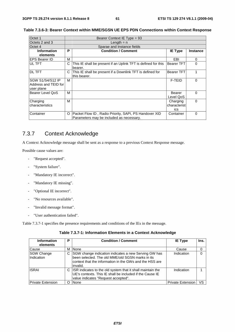
ETSI
ETSI TS 129 274 V8.1.1 (2009-04) 613GPP TS 29.274 version 8.1.1 Release 8
Table 7.3.6-3: Bearer Context within MME/SGSN UE EPS PDN Connections within Context Response
Octet 1 Bearer Context IE Type = 93 Octets 2 and 3 Length = n Octet 4 Sparae and Instance fields
Information elements
P Condition / Comment IE Type Instance
EPS Bearer ID M EBI 0 UL TFT C This IE shall be present if an Uplink TFT is defined for this
bearer. Bearer TFT 0
DL TFT C This IE shall be present if a Downlink TFT is defined for this bearer.
Bearer TFT 1
SGW S1/S4/S12 IP Address and TEID for user plane
M F-TEID 0
Bearer Level QoS M Bearer Level QoS
0
Charging characteristics
M Charging characterist
ics
0
Container O Packet Flow ID , Radio Priority, SAPI, PS Handover XID Parameters may be included as necessary.
Container 0
7.3.7 Context Acknowledge
A Context Acknowledge message shall be sent as a response to a previous Context Response message.
Possible cause values are:
- "Request accepted".
- "System failure".
- "Mandatory IE incorrect".
- "Mandatory IE missing".
- "Optional IE incorrect".
- "No resources available".
- "Invalid message format".
- "User authentication failed".
Table 7.3.7-1 specifies the presence requirements and conditions of the IEs in the message.
Table 7.3.7-1: Information Elements in a Context Acknowledge
Information elements
P Condition / Comment IE Type Ins.
Cause M None Cause 0 SGW Change Indication
C SGW change indication indicates a new Serving GW has been selected. The old MME/old SGSN marks in its context that the information in the GWs and the HSS are invalid.
Indication 0
ISRAI C ISR indicates to the old system that it shall maintain the UE's contexts. This IE shall be included if the Cause IE value indicates "Request accepted".
Indication 1
Private Extension O None Private Extension VS

ETSI
ETSI TS 129 274 V8.1.1 (2009-04) 623GPP TS 29.274 version 8.1.1 Release 8
7.3.8 Identification Request
If the UE identifies itself with temporary identity and it has changed SGSN/MME since detach in Attach procedure, the new MME/SGSN shall send an Identification Request message to the old SGSN/MME over S3, S16 or S10 interface to request IMSI.
Table 7.3.8-1 specifies the presence requirements and conditions of the IEs in the message.
If the sending node is a MME, it shall include in the Identification Request message:
• the GUTI IE and Complete Attach Request Message IE if the GUTI received from UE indicates the old node is a MME.
• the RAI IE, P-TMSI IE and P-TMSI Signature IE if the GUTI received from UE indicates the old node is an SGSN.
Editor's note: It is FFS if other means than GUTI could be needed to identify the old nodes.
If the sending node is an SGSN, it shall include RAI IE, P-TMSI IE and P-TMSI Signature IE in the Identification Request message.
The new MME differentiates the type of the old node from the most significant bit of the MME group id in GUTI. The value 0 indicates that the old node is an SGSN, the GUTI shall be mapped to RAI and P-TMSI by the new MME; and the value 1 indicates the old node is a MME, the new MME include GUTI IE and Complete Attach Request Message IE in the Identification Request message. The Mapping between temporary and area identities is defined in 3GPP TS 23.003 [2].
The GUTI IE shall not coexist with any of the RAI IE, P-TMSI IE and P-TMSI Signature IE in an Identification Request message. If this occurs, the receiving node shall return a corresponding cause value in the response message.
Table 7.3.8-1: Information Elements in an Identification Request
Information elements
P Condition / Comment IE Type Ins.
GUTI C The new MME shall include this IE over S10 interface. GUTI 0 Routeing Area Identity(RAI)
C This IE shall be included over S3/S16 interface, if the GUTI received from the UE indicates the old node is an SGSN, the new MME maps this IE from GUTI.
ULI for RAI 0
Packet TMSI(P-TMSI) C This IE shall be included over S3/S16 interface, if the GUTI received from the UE indicates the old node is an SGSN, the new MME maps this IE from GUTI.
P-TMSI 0
P-TMSI Signature C This IE shall be included over S3/S16 interface, if the GUTI received from the UE indicates the old node is an SGSN, the new MME maps this IE from GUTI.
P-TMSI Signature 0
Complete Attach Request Message
C The new MME shall include this IE over S10 interface, and the old MME may use this IE for integrity check.
Complete Request Message
0
Address for Control Plane
O If an SGSN within the same SGSN pool with the old SGSN receives this message, the SGSN shall include the old IP address of the received message in this optional parameter if this IE is not present and relay the message to the old SGSN.
IP Address 0
UDP Source Port Number
C If an SGSN within the same SGSN pool as the old SGSN receives this message, the SGSN shall include the UDP Source Port number of the received message in this optional parameter if this IE is not present and relay the message to the old SGSN. The old SGSN shall use this UDP port as the UDP destination port of the Identification Response message.
Port Number 0
Hop Counter O If an SGSN within the same SGSN pool with the old SGSN receives this message, the SGSN shall decrement the Hop Counter if this IE is present in the received message; otherwise may include a Hop Counter with a value of max-1, and relay the message to the old SGSN.
Hop Counter 0
Private Extension O None Private Extension VS

ETSI
ETSI TS 129 274 V8.1.1 (2009-04) 633GPP TS 29.274 version 8.1.1 Release 8
7.3.9 Identification Response
The old SGSN/MME shall send an Identification Response message to the new MME/SGSN as a response to a previous Identification Request message over S3/S10/S16 interface.
Table 7.3.9-1 specifies the presence requirements and conditions of the IEs in the message.
For Intra Domain Connection of RAN Nodes to Multiple CN Nodes, if an old SGSN within an SGSN pool receives an Identification Request message that contains the optional parameter Address for Control Plane, the old SGSN shall use this address as destination IP address of the Identification Response message.
Possible Cause values are:
- "Request accepted"
- "IMSI not known"
- "System failure"
- "Mandatory IE incorrect"
- "Mandatory IE missing"
- "Optional IE incorrect"
- "Invalid Message format"
- "P-TMSI Signature mismatch"
- "User authentication failed"
Only the Cause information element shall be included in the response if the Cause contains another value than "Request accepted".
Table 7.3.9-1: Information Elements in an Identification Response
Information elements
P Condition / Comment IE Type Ins.
Cause M Cause 0 IMSI C This IE is mandatory if the Cause contains the value
"Request accepted". IMSI 0
MME/SGSN UE MM Context
C This IE shall be included if Attach Request is integrity protected
MM Context 0
Private Extension O Private Extension VS
7.3.10 Forward Access Context Notification
A Forward Access Context Notification message shall be sent from the Old SGSN to the New SGSN over the S16 interface to forward the RNC contexts to the target system, or sent from the Old MME to the New MME over the S10 interface to forward the RNC/eNodeB contexts to the target system.
When the old SGSN receives the RANAP message Forward SRNS Context, the old SGSN shall send a Forward Access Context Notification message to the new SGSN. The new SGSN shall forward the message to the target RNC using the corresponding RANAP message.
When the old SGSN receives a BSSGP message PS handover Required and the acknowledged peer-to-peer LLC operation is used for the Bearer Context or when "delivery order" is set in the Bearer Context QoS profile, the old SGSN shall send a Forward Access Context Notification message with the PDU Number IE to the new SGSN. The new SGSN shall forward the message to the target RNC/ target BSS using the corresponding RANAP message only for PS handover to Iu mode.
When the old SGSN receives a BSSGP message PS handover Required from source BSS/RNC for PS handover to A/Gb mode, the value part of RAB Context IE shall be empty according to its defined minimum length.

ETSI
ETSI TS 129 274 V8.1.1 (2009-04) 643GPP TS 29.274 version 8.1.1 Release 8
Table 7.3.10-1 specifics the presence requirements and conditions of the IEs in the message.
Table 7.3.10-1: Information Elements in a Forward Access Context Notification
Information elements
P Condition / Comment IE Type Ins.
RAB Contexts C This IE shall be included for S16 only. Several IEs with this type and instance values shall be included as necessary to represent a list of Bearers. For each RAB context in the received RANAP message, the old SGSN shall include this IE in the message.
RAB Context 0
Source RNC PDCP context Info
O If available, the old SGSN shall include an Source RNC PDCP context info in the message.
Source RNC PDCP context
Info
0
PDU Numbers O This IE only applies to S16. The old SGSN shall include this IE in the message if the acknowledged peer-to-peer LLC operation is used for the Bearer Context or when "delivery order" is set in the Bearer Context QoS profile in A/Gb mode to Iu/A/Gb mode PS handover.
PDU Numbers 0
E-UTRAN Transparent Container
C This IE shall be included over S10 to contain the eNodeB Status Transfer Transparent Container IE specified in S1-AP.
F-Container 0
Private Extension O Private Extension VS
7.3.11 Forward Access Context Acknowledge
A Forward Access Context Acknowledge message shall be sent to the old SGSN as a response to Forward SRNS Context Notification.
Possible Cause values are:
- "Request Accepted".
- "Mandatory IE incorrect".
- "Mandatory IE missing".
- "Optional IE incorrect".
- "Invalid message format".
Table 7.3.11-1 specifics the presence requirements and conditions of the IEs in the message.
Table 7.3.11-1: Information Elements in a Forward Access Context Acknowledge
Information elements
P Condition / Comment IE Type Ins.
Cause M Cause 0 Private Extension O Private Extension VS
7.3.12 Detach Notification
A Detach Notification message shall be sent from an MME to the associated SGSN, or from an SGSN to the associated MME as a part of Detach procedure if the ISR is activated between the MME and SGSN for the UE.
Possible Cause values are:
- "Local Detach".
- "Complete Detach".

ETSI
ETSI TS 129 274 V8.1.1 (2009-04) 653GPP TS 29.274 version 8.1.1 Release 8
"Local Detach" indicates that this detach is local to the MME/SGSN and so the associated SGSN/MME registration where the ISR is activated shall not be detached. The MME/SGSN that receives this message including this Cause value of "Local Detach" only deactivates the ISR. This Cause value shall be included in the procedures:
- MME/SGSN-initiated Detach Procedure in case of implicit detach.
- HSS-initiated Detach Procedure.
"Complete Detach" indicates both the MME registration and the SGSN registration that the ISR is activated for, shall be detached. This "Complete Detach" Cause value shall be included in the procedures:
- UE-initiated Detach Procedure.
- MME/SGSN-initiated Detach Procedure in case of explicit detach.
Table 7.3.12-1 specifics the presence of the IEs in the message.
Table 7.3.12-1: Information Elements in a Detach Notification
Information elements
P Condition / Comment IE Type Ins.
IMSI M None IMSI 0 Cause M None Cause 0 Private Extension O None Private Extension VS
Editor's notes: It is FFS whether there is more Information Element for this message.
7.3.13 Detach Acknowledge
A Detach Acknowledge message shall be sent as a response to a Detach Notification message during Detach procedure.
Possible Cause values are:
- "Request accepted".
- "IMSI not known".
- "System failure".
- "Mandatory IE incorrect".
- "Mandatory IE missing".
- "Optional IE incorrect".
- "Invalid Message format"
Editor's note: Other potential Cause values are FFS.
Table 7.3.13-1 specifics the presence of the IEs in the message.
Table 7.3.13-1: Information Elements in a Detach Acknowledge
Information elements
P Condition / Comment IE Type Ins.
Cause M None Cause 0 Recovery O None Recovery 0 Private Extension O None Private Extension VS
Editor's notes: It is FFS whether there is more Information Element for this message.

ETSI
ETSI TS 129 274 V8.1.1 (2009-04) 663GPP TS 29.274 version 8.1.1 Release 8
7.3.14 Change Notification Request
The Change Notification Request message is sent on the S4 interface by the SGSN to the SGW and on the S5/S8 interface by the SGW to the PGW as part of location dependent charging related procedures.
The TEID value used in this message shall be zero.
Table 7.3.14-1: Information Element in Change Notification Request
Information elements
P Condition / Comment IE Type Ins.
IMSI M None IMSI 0 RAT Type M None RAT Type 0 User Location Information (ULI)
C The SGSN shall include the User Location Information IE if the MS is located in a RAT Type of GERAN, UTRAN or GAN and shall include the CGI, SAI or RAI in the "Geographic Location" field depending on whether the MS is in a cell, a service or a routing area respectively.
ULI 0
PGW S5/S8 GTP-C IP Address
C This IE shall be sent on S4. IP Address 0
Private Extension O Vendor or operator specific information Private Extension VS
7.3.15 Change Notification Response
The Change Notification Request message is sent on the S4 interface by the SGW to the SGSN and on the S5/S8 interface by the PGW to the SGW as part of location dependent charging related procedures to acknowledge the receipt of a Change Notification Request.
The Cause value indicates whether or not the Change Notification Request was received correctly. Possible Cause values are:
- "Request accepted".
- "Request accepted partially".
- "Request rejected".
- "Invalid message format".
- "IMSI not known".
- "Mandatory IE incorrect".
- "Mandatory IE missing".
- "Optional IE incorrect".
- "System failure".
The TEID value used in this message shall be zero.
If the IMSI is unknown for the receiving GTP-C entity, then the message shall be silently discarded and no further processing of the IEs shall continue.
If the received Change Notification Response contains a Cause value of "IMSI not known", then the Change Reporting mechanism shall be stopped in the receiving SGSN for all Bearers associated with the IMSI received and the PGW from which the "IMSI not known" was occurred. The SGSN shall then initiate PDN disconnection for all of these PDN Connections associated with the PGW.
If the location Change Reporting mechanism is to be stopped for this subscriber in the SGSN, then the PGW shall include the Change Reporting Action IE in the message and shall set the value of the Action field appropriately.

ETSI
ETSI TS 129 274 V8.1.1 (2009-04) 673GPP TS 29.274 version 8.1.1 Release 8
Table 7.3.15-1: Information Element in Change Notification Response
Information elements
P Condition / Comment IE Type Ins.
IMSI M None IMSI 0 Cause M None Cause 0 Change Reporting Action
C This IE shall be included with the appropriate Action field If the location Change Reporting mechanism is to be started or stopped for this subscriber in the SGSN/MME.
Change Reporting Action
0
Private Extension O Vendor or operator specific information Private Extension VS
7.3.16 Relocation Cancel Request
A Relocation Cancel Request message shall be sent from the source MME/SGSN to the target MME/SGSN on S3/S10/S16 interface as part of the Inter RAT handover Cancel procedure and on the S16 interface as part of the SRNS Relocation Cancel Procedure.Table 7.3.16-1 specifics the presence of the IEs in the message.
Table 7.3.16-1: Information Elements in Relocation Cancel Request
Information elements
P Condition / Comment IE Type Ins.
IMSI M IMSI 0 RANAP Cause C This IE shall be present in the case of SRNS relocation
cancel procedure. It shall contain the cause value received from the source RNC in the Relocation Cancel message received over the Iu interface.
F-Cause 0
Private Extension O Private Extension VS
7.3.17 Relocation Cancel Response
A Relocation Cancel Response message shall be sent as a response to a previous Relocation Cancel Request message during the Inter RAT handover Cancel procedure or the SRNS Relocation Cancel Procedure.
Possible Cause values are:
- "Request Accepted".
- "IMSI not known".
- "System failure".
- "Mandatory IE incorrect".
- "Mandatory IE missing".
- "Optional IE incorrect".
- "Invalid message format".
Table 7.3.17-1 specifics the presence of the IEs in the message.
Table 7.3.17-1: Information Elements in Relocation Cancel Response
Information elements
P Condition / Comment IE Type Ins.
Cause M Cause 0 Private Extension O Private Extension VS

ETSI
ETSI TS 129 274 V8.1.1 (2009-04) 683GPP TS 29.274 version 8.1.1 Release 8
7.3.18 Configuration Transfer Tunnel
A Configuration Transfer Tunnel message shall be used to tunnel eNodeB Configuration Transfer messages from a source MME to a target MME over the S10 interface. The purpose of the eNodeB Direct Configuration Transfer is to transfer information from an eNodeB to another eNodeB in unacknowledged mode (see 3GPP TS 36.413 [10]).
Table 7.3.18-1 specifies the presence requirements and conditions of the IEs in the message.
Table 7.3.18-1: Information Elements in a Configuration Transfer Tunnel Message
Information elements
P Condition / Comment IE Type Ins.
E-UTRAN Transparent Container
M This IE shall contain the SON transfer IE.
F-Container 0
Target eNodeB ID M This IE shall contain the ID of the target eNodeB Target Identification
0
7.3.19 RAN Information Relay
The RAN Information Relay message shall be sent on S3 interface between SGSN and MME to transfer the RAN information received by an SGSN from BSS or RNS (GERAN Iu mode) or by an MME from eNodeB. The procedures are specified in 3GPP TS 23.401 [3].
This IE shall also be sent on S16 interface to transfer the RAN information between GERAN or GERAN Iu mode and UTRAN.
For handling of protocol errors the RAN Information Relay message is treated as a Response message.
Table 7.3.19-1 specifies the presence requirements and conditions of the IEs in the message.
Table 7.3.19-1: Information Elements in a RAN Information Relay
Information elements
P Condition / Comment IE Type Ins.
RAN Transparent Container
M All information elements from the RIM messages, starting from and including the BSSGP "PDU type", shall be contained within the RAN Transparent Container and forwarded to the destination MME/SGSN in the RAN Information Relay message.
F-Container 0
RIM Routing Address C This IE shall be included if the RIM Routing Address information is included in the message sent from the source RAN node This IE identifies the destination RAN node where the RAN Information needs to be relayed to. It contains the destination RNC Identity when the source is E-UTRAN/UTRAN and the target is GERAN Iu mode or the destination Cell Identity when the source is E-UTRAN/UTRAN and the target is GERAN or the destination global eNodeB ID when the source is GERAN and the target is E-UTRAN.
Target Identification
0
Private Extension O None Private Extension VS
7.4 CS Fallback related messages
7.4.1 Suspend Notification
The Suspend Notification message shall be sent on the S11 interface by the MME to the SGW as part of the CS fallback from E-UTRAN access to UTRAN/GERAN CS domain access related procedures.

ETSI
ETSI TS 129 274 V8.1.1 (2009-04) 693GPP TS 29.274 version 8.1.1 Release 8
Table 7.4.1-1: Information Element in Suspend Notification
Information elements
P Condition / Comment IE Type Ins.
IMSI M IMSI 0 Private Extension O Private Extension VS
7.4.2 Suspend Acknowledge
The Suspend Acknowledge message shall be sent on the S11 interface by the SGW to the MME as part of the CS fallback from E-UTRAN access to UTRAN/GERAN CS domain access related procedures.
Table 7.4.2-1: Information Element in Suspend Acknowledge
Information elements
P Condition / Comment IE Type Ins.
IMSI M IMSI 0 Private Extension O Private Extension VS
7.4.3 Resume Notification
The Resume Notification message shall be sent on the S11 interface by the MME to the SGW as part of the resume procedure returning from CS fallback to E-UTRAN.
Table 7.4.3-1: Information Element in Resume Notification
Information elements
P Condition / Comment IE Type Ins.
IMSI M IMSI 0 Private Extension O Private Extension VS
7.4.4 Resume Acknowledge
The Resume Acknowledge message shall be sent on the S11 interface by the SGW to the MME as part of the resume procedure returning from CS fallback to E-UTRAN.
Table 7.4.4-1: Information Element in Resume Acknowledge
Information elements
P Condition / Comment IE Type Ins.
IMSI M IMSI 0 Private Extension O Private Extension VS
7.4.5 CS Paging Indication
The CS Paging Indication shall be sent on the S3 interface by the MME to the associated SGSN when ISR is activated as part of mobile terminated CS services. The MME gets the related information from SGsAP-PAGING-REQUEST message as specified in 3GPP TS29.118 [21].Table 7.4.5-1 specifies the presence requirements and the conditions of the IEs in the message.

ETSI
ETSI TS 129 274 V8.1.1 (2009-04) 703GPP TS 29.274 version 8.1.1 Release 8
Table 7.4.5-1: Information Element in CS Paging Indication
Information elements
P Condition / Comment IE Type Ins.
IMSI M IMSI 0 VLR Number M FFS 0 TMSI O TMSI 0 Location area identifier
O ULI 0
Global CN-Id O Global CN-Id 0 Channel needed O Channel needed 0 eMLPP Priority O eMLPP Priority 0
7.5 Non-3GPP access related messages
7.5.1 Create Forwarding Tunnel Request
A Create Forwarding Tunnel Request message shall be sent by a MME to a Serving GW as a part of the MME configures resources for indirect data forwarding during active handover procedure from E-UTRAN to CDMA 2000 HRPD access.
Table 7.5.1-1 specifies the presence requirements and the conditions of the IEs in the message.
Table 7.5.1-1: Information Elements in a Create Forwarding Tunnel Request
Information elements
P Condition / Comment IE Type Ins.
S103 PDN Data Forwarding Info
M The MME shall include the forwarding Infomation for all PDN connections of the UE requesting data forwarding towards the HSGW in the message as S103 PDN Data Forwarding Info information elements. The Serving GW shall forward downlink data to the HSGW via the GRE tunnel identified by the HSGW Address and HSGW GRE Key included in this information element when it receives downlink data forwarded from the eNodeB belonging to the corresponding EPS bearers of the PDN connection.
S103PDF 0
7.5.2 Create Forwarding Tunnel Response
A Create Forwarding Tunnel Response message shall be sent by a Serving GW to a MME as a response to a Create Forwarding Tunnel Request message.
Table 7.5.2-1 specifies the presence requirements and the conditions of the IEs in the message.
The Cause value indicates if Data Forwarding Resources has been created in the Serving GW or not. Data Forwarding Resources have not been created in the Serving GW if the Cause differs from "Request accepted". Possible Cause values are:
- "Request Accepted".
- "No resources available".
- "System failure".
- "Mandatory IE incorrect".
- "Mandatory IE missing".
- "Optional IE incorrect".
- "Invalid message format".

ETSI
ETSI TS 129 274 V8.1.1 (2009-04) 713GPP TS 29.274 version 8.1.1 Release 8
Only the Cause IE shall be included in the response if the Cause IE contains another value than "Request accepted".
Table 7.5.2-1: Information Elements in a Create Forwarding Tunnel Response
Information elements
P Condition / Comment IE Type Ins.
Cause M None Cause 0 S1-U Data Forwarding Info
C S1-U Data Forwarding Info shall be included in the message if the Cause contains the value "Request accepted". For each EPS bearer requesting data forwarding which is included in the S103 PDN Data Forwarding Info fields of corresponding Create Forwarding Tunnel Request message, the Serving GW shall assign a Serving GW S1-U Address and Serving GW S1-U TEID pair and included it in the response message as S1-U Data Forwarding Info information element. The eNodeB shall forward downlink data of the EPS bearer to the Serving GW via the GTP-U tunnel identified by the Serving GW S1-U Address and Serving GW S1-U TEID.
S1UDF 0
7.6 Reliable Delivery of Signalling Messages For each triplet of local IP address, local UDP port and remote peer's IP address a GTP entity maintains a queue with signalling messages to be sent to that peer. The message at the front of the queue, if it is a request for which a response has been defined, shall be sent with a Sequence Number, and shall be held in a list until a response is received. The same provision is applicable to notification messages with an associated acknowledge message. The Sequence Number shall be unique for each outstanding request message sourced from the same IP/UDP endpoint. A node running GTP may have several outstanding requests while waiting for responses. A single request shall be answered with a single response, regardless whether it is per UE, per APN, or per bearer. A request / response pair of messages shall have the same sequence number.
The Sequence Number shall be unique for each outstanding notification message sourced from the same IP/UDP endpoint. A node running GTP may have several outstanding notifications while waiting for acknowledge messages. A single notification shall be answered with a single acknowledge, regardless whether it is per UE, per APN, or per bearer. A notification / acknowledge pair of messages shall have the same sequence number.
In the specific case of GTP Command Messages which do not have an explicit response, but which trigger a Request Message, the sequence number used by Command Message shall be the same for all three messages: the Command, the triggered Request and the corresponding Response messages.
A sequence number used for a Command Message and its associated messages shall have the most significant bit set to 1. A sequence number used for a Request Message not triggered by a Command Message shall have the most significant bit set to 0.
This setting of the most significant bit of the sequence number is done to avoid potential clashes between the sequence number selected for a Command Message, and the sequence number selected by a GTP peer for a Request Message which was not triggered by a Command Message.
A timer shall be started when a signalling request message (for which a response has been defined) is sent. A signalling message request or response has probably been lost if a response has not been received before the timer expires.
A timer shall be started when a notification message (for which an acknowledge messages has been defined) is sent. A notification or acknowledge message has probably been lost if a response has not been received before the timer expires.
A timer shall be started when a command message is sent. A command or request message has probably been lost if a request has not been received before the timer expires.
Once a timer expires, the request is then retransmitted if the total number of request attempts is less than N3-REQUESTS times. T3-RESPONSE timer and N3-REQUESTS counter setting is implementation dependent. That is, the timers and counters may be configurable per procedure. Multileg communications (e.g. Create Session Requests and Responses) however require longer timer values and possibly a higher number of retransmission attempts compared to single leg communication.

ETSI
ETSI TS 129 274 V8.1.1 (2009-04) 723GPP TS 29.274 version 8.1.1 Release 8
All received request messages shall be responded to and all response messages associated with a certain request shall always include the same information. Duplicated response messages shall be discarded. A response message without a matching outstanding request should be considered as a duplicate.
If a GTPv2 node is not successful with the transfer of a non-Echo signalling message, e.g. a Create Bearer Context Request message, it shall inform the upper layer of the unsuccessful transfer so that the controlling upper entity may take the necessary measures.
7.7 Error Handling
7.7.1 Protocol Errors
A protocol error is defined as a message or an Information Element received from a peer entity with unknown type, or if it is unexpected, or if it has an erroneous content.
The term silently discarded is used in the following subclauses to mean that the receiving GTP entity's implementation shall discard such a message without further processing, or that the receiving GTP entity discards such an IE and continues processing the message. The conditions for the receiving GTP entity to silently discard an IE are specified in the subsequent subclauses.
The handling of unknown, unexpected or erroneous GTP messages and IEs shall provide for the forward compatibility of GTP. Therefore, the sending GTP entity shall be able to safely include in a message a new conditional or an optional IE. Such an IE may also have a new type value. Any legacy receiving GTP entity shall, however, silently discard such an IE and continue processing the message.
If a protocol error is detected by the receiving GTP entity, it should log the event including the erroneous message and should include the error in a statistical counter.
An information element with "Mandatory" in the "Presence requirement" column of a message definition shall always be present in that message.
An information element with "Conditional" in the "Presence requirement" column of a message definition shall be sent when the conditions detailed in the "Presence requirement" are met.
The Version Not Supported Indication message shall be considered as Response for the purpose of this subclause.
The receiving GTP entity shall apply the error handling specified in the subsequent subclauses in decreasing priority.
If the received erroneous message is a response to a pending GTP request message, the GTP transaction layer shall stop retransmissions and notify the GTP application layer of the error even if the response is silently discarded.
7.7.2 Different GTP Versions
If a GTP entity receives a message of an unsupported GTP version, it shall return a Version Not Supported Indication message and discard the received message.
7.7.3 GTP Message of Invalid Length
If a GTP entity receives a message, which is too short to contain the respective GTPv2 header, the GTP-PDU shall be silently discarded.
Apart from a piggybacked GTP message, if a GTP entity receives a Request message of a length that is different from the value specified in the Length field of the GTP header, then the receiving GTP entity should log the error and shall send the Response message with Cause IE value set to "Invalid Length". Piggybacked message is identified by P flag set to 1 in the received GTP message header.
If a GTP entity receives a Response message of a length that is different from the value specified in the Length field of the GTP header, then the receiving GTP entity should log the error and shall silently discard the message.

ETSI
ETSI TS 129 274 V8.1.1 (2009-04) 733GPP TS 29.274 version 8.1.1 Release 8
7.7.4 Unknown GTP Message
If a GTP entity receives a message with an unknown Message Type value, it shall silently discard the message.
7.7.5 Unexpected GTP Message
If a GTP entity receives an unexpected initial message (see subclause 4.3 "Protocol stack"), it shall be silently discard the message and shall log an error.
If a GTP entity receives an unexpected triggered message (see subclause 4.3 "Protocol stack"), it shall discard the message and may log an error.
7.7.6 Missing Information Elements
A GTP entity shall check if all mandatory IEs are present in the received Request message. If one or more mandatory information elements are missing, the GTP entity should log the error and shall send a Response message with Cause IE value set to "Mandatory IE missing" together with the type value of the missing mandatory IE.
If a GTP entity receives a Response message with Cause IE value set to "Mandatory IE missing", it shall notify its upper layer.
A GTP entity shall check if all mandatory IEs are present in the received Response message. If one or more mandatory information elements are missing, the GTP entity shall notify the upper layer and should log the error.
A GTP entity shall check if conditional information elements are present in the received message, if possible (i.e. if the receiving entity has sufficient information available to check if the respective conditions were met).
When possible, a GTP entity shall check if all conditional IEs are present in the received Request message. If one or more conditional information elements are missing, GTP entity should log the error and shall send a Response message with Cause IE value set to "Conditional IE missing" together with the type value of the missing conditional IE.
When possible, a GTP entity shall check if all conditional IEs are present in the received Response message. If one or more conditional information elements are missing, GTP entity shall notify the upper layer and should log the error.
Absence of an optional information element shall not trigger any of the error handling processes.
7.7.7 Invalid Length Information Element
An information element has invalid length when the actual length of the IE is different from the value of the Length field in the IE header.
If a GTP message contains more than one information elements and one or more of them have invalid length, the receiving GTP entity can detect which of the IEs have invalid length only in the following cases:
- If the Length value in the IE header is greater than the overall length of the message;
- If the invalid length IE is the last one in the message.
Other Length field handling cases are specified below:
- If the received value of the Length field in the fixed length IE is greater than that expected by the fixed number of octets, then the extra octets shall be discarded.
- If the received value of the Length field in the fixed length IE is less than that expected by the fixed number of octets, this shall be considered an error, IE shall be discarded and an appropriate error response shall be returned to the sender.
- If the received value of the Length field in the extendable length IE is greater than that expected by the fixed number of octets preceding the extended field(s), then the extra unknown octets shall be discarded.
- If the received value of the Length field in the extendable length IE is less than that expected by the fixed number of octets preceding the extended field(s), this shall be considered an error, IE shall be discarded and an appropriate error response shall be returned to the sender.

ETSI
ETSI TS 129 274 V8.1.1 (2009-04) 743GPP TS 29.274 version 8.1.1 Release 8
7.7.8 Semantically incorrect Information Element
The receiver of a GTP signalling message Request including a mandatory or a verifiable conditional information element with a semantically invalid Value shall discard the request, should log the error, and shall send a response with Cause set to "Mandatory IE incorrect" together with a type value of the offending IE.
The receiver of a GTP signalling message Response including a mandatory or a checkable conditional information element with a semantically invalid Value shall notify the upper layer that a message with this sequence number has been received and should log the error. ""If a GTP entity receives an information element with a value which is shown as reserved, it shall treat that information element as invalid and should log the error. It shall send a response with Cause set to "Reserved Message Value Received" together with a type value of the offending message.
The principle is: the use of reserved values invokes error handling; the use of spare values can be silently discarded and so in the case of IEs with spare values used, processing shall be continued ignoring the spare values.
The receiver of a GTP signalling message including an optional information element with a Value that is not in the range defined for this information element value shall discard this IE, but shall treat the rest of the message as if this IE was absent and continue processing. The receiver shall not check the content of an information element field that is defined as 'spare".
All semantically incorrect optional information elements in a GTP signalling message shall be treated as not present in the message.
7.7.9 Unknown or unexpected Information Element
The receiver of a GTP message including an unexpected information element with known Type value, but with the instance value that is not defined for this message shall discard the IE and log an error. The receiver shall process the message.
An information element with a Type value which is defined in section 8.1 of the present specification but whose Instance Value is not expected in the received GTP signalling message according to the grammar defined in section 7.1 to 7.5 of the present specification shall be silently discarded (skipped) and the rest of the message processed as if this information element was not present.
NOTE: An Information Element in an encoded GTPv2 message or grouped IE is identified by the pair of IE Type and Instance value.
7.7.10 Repeated Information Elements
An Information Element is repeated if there is more than one IE with the same IE Type and Instance in the scope of the GTP message (scope of the grouped IE). Such an IE is a member in a list.
If an information element is repeated in a GTP signalling message in which repetition of the information element is not specified, only the contents of the information element appearing first shall be handled and all subsequent repetitions of the information element shall be ignored. When repetition of information elements is specified, only the contents of specified repeated information elements shall be handled and all subsequent repetitions of the information element shall be ignored.
7.8 Path Failure Restoration and Recovery procedures are specified generally in 3GPP TS 23.007 [17] and a path failure may initiate recovery procedures.
Path failure is detected only by using Echo Request / Response messages in the following way. A peer's IP address specific counter shall be reset each time an Echo Response message is received from that peer's IP address and incremented when the T3-RESPONSE timer expires for an Echo Request message sent to that peer's IP address. The path shall be considered to be down if the counter exceeds N3-REQUESTS. In this case, the GTP entity may notify the Operation and Maintenance network element. GTP shall also notify the upper layer of the path failure, so that PDN connections or PDP contexts associated with this peer's IP address may be deleted.

ETSI
ETSI TS 129 274 V8.1.1 (2009-04) 753GPP TS 29.274 version 8.1.1 Release 8
7.9 Restoration and Recovery Restoration and Recovery procedures are specified in 3GPP TS 23.007 [17].
7.9.1 Delete PDN Connection Set Request
This message is sent on S5, S8, or S11 interfaces. The message sent by MME shall be forwarded by the SGW to PGW. The message sent by the PGW shall be forwarded by SGW to MME.A node sends this message when a partial failure affects a set of its PDN connections for which CSID has been previously assigned. The receiving node identifies the set of PDN connections associated with the FQ-CSID from its PDN connection table, and marks them for deletion. As covered in 3GPP TS 23.007 [17] a MME, SGW or PGW that experiences a partial fault and sends a Delete PDN Connection Set Request to each of its immediate neighboring peers need not do any further recovery actions towards any peer for the PDN connections identified by the FQ-CSID.
Table 7.9.1-1: Information Elements in a Delete PDN Connection Set Request
Information elements
P Condition / Comment IE Type Ins.
MME-FQ-CSID C Shall be included when a MME reports a partial fault. More than one FQ-CSID may appear
FQ-CSID 0
SGW-FQ-CSID C Shall be included when a SGW reports a partial fault. More than one FQ-CSID may appear
FQ-CSID 1
PGW-FQ-CSID C Shalll be included when a PGW reports a partial fault. More than one FQ-CSID may appear
FQ-CSID 2
Private Extension O None Private Extension VS
TEID of 0 shall be used for the Delete PDN Connection Set Request. A GTPv2 entity shall be able to accept and process any Delete PDN Connection Set Request on any S5, S8 or S11 control plane interface.
The SGW shall "relay" the Delete PDN Connection Set Request it receives from a MME to the PGW and from a PGW to a MME as stated in 3GPP TS 23.007 [17].
Only one type of FQ-CSID shall be included in each Delete PDN Connection Set Request, A mix of different types, such as SGW-FQ-CSID and PGW-FQ-CSID shall not be used. A combined node, such as a collocated PGW/SGW, shall send separate Delete PDN Connection Set Request for the PGW role and one for the SGW role if a partial fault impacts more than one role.
7.9.2 Delete PDN Connection Set Response
This message is sent as a response to the Delete PDN Connection Set Request.
Table 7.9.2: Information Elements in a Delete PDN Connection Set Response
Information elements
P Condition / Comment IE Type Ins.
Cause M Cause 0 Private Extension O None Private Extension VS
TEID of 0 shall be used for the Delete PDN Connection Set Response.
The following Cause values are defined:
- "Success"
- "Request rejected"
"Success" indicates the receiving node was capable of storing a CSID value for each PDN connection for the type of node (MME,SGW or PGW) in the Delete PDN Connection Set Request and has marked, or will mark immediately, the PDN connections for deletion as per 3GPP TS 23.007 [17]. "Success" shall be returned even if there are no PDN connections that match.

ETSI
ETSI TS 129 274 V8.1.1 (2009-04) 763GPP TS 29.274 version 8.1.1 Release 8
"Request rejected" shall be used when the receiver of the Delete PDN Connection Set Request is not capable of storing at least one CSID value per PDN connection for the type of node (MME, SGW or PGW) received in the Delete PDN Connection Set Request.
The SGW shall not "relay" the Delete PDN Connection Set Response and shall respond to the Delete PDN Connection Set Request independently without waiting for replies.
7.10 Fallback to GTPv1 mechanism An EPC entity shall assume that each GTP processing node that it is about to communicate with is GTPv2 capable, i.e. before the first GTP tunnel is setup for a given UE/node, the EPC node shall always send a version 2 (GTPv2) message to a peer node.
A GTPv2 entity shall fallback to GTPv1 only if:
- a "Version Not Supported" message in GTPv1 format as specified in 3GPP TS 29.060 [4] is received from the peer node;
- Fallback to GTPv1 shall not occur on already established GTP tunnels without change of the peer nodes of the communication bearer.
7.11 Fallback to GTPv0 Fallback from GTPv2 to GTPv0 shall not be supported. Therefore, GTPv2 entity should not listen to the well-known GTPv0 port 3386. If GTPv2 entity listens to the GTPv0 port, the entity shall silently discard any received GTPv0 message.
7.12 Trace Management Messages
7.12.1 Trace Session Activation
The Trace Session Activation message shall be sent on S11 by the MME to the SGW, and on S5/S8 by the SGW to the PGW when session trace is activated for a particular IMSI or IMEI for a UE that is attached and active or attached and idle.
Table 7.12.1-1 specifies the presence of the IEs in the message.
Table 7.12.1-1: Information Elements in a Trace Session Activation
Information elements
P Condition / Comment IE Type Ins.
IMSI M IMSI 0 Trace Information M Trace Information 0 ME Identity (MEI) C The MME shall include the ME Identity (MEI) IE, if
available. MEI 0
7.12.2 Trace Session Deactivation
The Trace Session Deactivation message shall be sent on S11 by the MME to the SGW, and on S5/S8 by the SGW to the PGW when session trace is deactivated for a particular IMSI or IMEI for a UE that is attached and active or attached and idle.
Table 7.12.2-1 specifies the presence of the IEs in the message.

ETSI
ETSI TS 129 274 V8.1.1 (2009-04) 773GPP TS 29.274 version 8.1.1 Release 8
Table 7.12.2-1: Information Elements in a Trace Session Deactivation Request
Information elements
P Condition / Comment IE Type Ins.
Trace Reference M Trace Reference 0
8 GTP-C Information Elements
8.1 Information Element Types A GTP control plane (signalling) message may contain several information elements. In order to have forward compatible type definitions for the GTPv2 information elements, all of them shall be TLIV (Type, Length, Instance, Value) coded. GTPv2 information element type values are specified in the Table 8.1-1. The last column of this table indicates whether the information element is:
- Fixed Length: the IE has a fixed set of fields, and a fixed number of octets.
- Variable Length: the IE has a fixed set of fields, and has a variable number of octets. For example, the last octets may be numbered similar to "5 to (n+4)". In this example, if the value of the length field, n, is 0, then the last field is not present.
- Extendable: the IE has a variable number of fields, and has a variable number of octets. The last fields are typically specified with the statement: "These octet(s) is/are present only if explicitly specified".
In order to improve the efficiency of troubleshooting, it is recommended that the information elements should be arranged in the signalling messages as well as in the grouped IEs, according to the order the information elements are listed in the message definition table or grouped IE definition table in section 7. However the receiving entity shall be prepared to handle the messages with information elements in any order.
Within information elements, certain fields may be described as spare. These bits shall be transmitted with the value set to 0. To allow for future features, the receiver shall not evaluate these bits. GTPv2-C information elements that have similar semantics in GTPv1-C shall be converted into GTPv1-C format, as specified in TS 29.060 [4], before sending them to pre-R8 SGSN.

ETSI
ETSI TS 129 274 V8.1.1 (2009-04) 783GPP TS 29.274 version 8.1.1 Release 8
Table 8.1-1: Information Element types for GTPv2
IE Type value (Decimal)
Information elements Comment / Reference
0 Reserved 1 International Mobile Subscriber Identity (IMSI) Variable Length / 8.3 2 Cause Variable Length / 8.4 3 Recovery (Restart Counter) Variable Length / 8.5
4 to 50 Reserved for S101 interface Extendable / See 3GPP TS 29.276 [14] 51 to 70 Reserved for Sv interface Extendable / See 3GPP TS 29.280 [15]
71 Access Point Name (APN) Variable Length / 8.6 72 Aggregate Maximum Bit Rate (AMBR) Fixed Length / 8.7 73 EPS Bearer ID (EBI) Extendable / 8.8 74 IP Address Variable Length / 8.9 75 Mobile Equipment Identity (MEI) Variable Length / 8.10 76 MSISDN Variable Length / 8.11 77 Indication Extendable / 8.12 78 Protocol Configuration Options (PCO) Variable Length / 8.13 79 PDN Address Allocation (PAA) Variable Length / 8.14 80 Bearer Level Quality of Service (Bearer QoS) Variable Length / 8.15 81 Flow Quality of Service (Flow QoS) Extendable / 8.16 82 RAT Type Extendable / 8.17 83 Serving Network Extendable / 8.18 84 EPS Bearer Level Traffic Flow Template (Bearer TFT) Variable Length / 8.19 85 Traffic Aggregation Description (TAD) Variable Length / 8.20 86 User Location Info (ULI) Variable Length / 8.21 87 Fully Qualified Tunnel Endpoint Identifier (F-TEID) Extendable / 8.22 88 TMSI Variable Length / 8.23 89 Global CN-Id Variable Length / 8.24 90 S103 PDN Data Forwarding Info (S103PDF) Variable Length / 8.25 91 S1-U Data Forwarding Info (S1UDF) Variable Length/ 8.26 92 Delay Value Extendable / 8.27 93 Bearer Context Extendable / 8.28 94 Charging ID Extendable / 8.29 95 Charging Characteristics Extendable / 8.30 96 Trace Information Extendable / 8.31 97 Bearer Flags Extendable / 8.32 98 Paging Cause Variable Length / 8.33 99 PDN Type Extendable / 8.34
100 Procedure Transaction ID Extendable / 8.35 101 DRX Parameter Variable Length/ 8.36 102 UE Network Capability Variable Length / 8.37 103 MM Context (GSM Key and Triplets) Variable Length / 8.38 104 MM Context (UMTS Key, Used Cipher and Quintuplets) Variable Length / 8.38 105 MM Context (GSM Key, Used Cipher and Quintuplets) Variable Length / 8.38 106 MM Context (UMTS Key and Quintuplets) Variable Length / 8.38 107 MM Context (EPS Security Context, Quadruplets and Quintuplets) Variable Length / 8.38 108 MM Context (UMTS Key, Quadruplets and Quintuplets) Variable Length / 8.38 109 PDN Connection Extendable / 8.39 110 PDU Numbers Extendable / 8.40 111 P-TMSI Variable Length / 8.41 112 P-TMSI Signature Variable Length / 8.42 113 Hop Counter Extendable / 8.43 114 UE Time Zone Variable Length / 8.44 115 Trace Reference Fixed Length / 8.45 116 Complete Request Message Variable Length / 8.46 117 GUTI Variable Length / 8.47 118 F-Container Variable Length / 8.48 119 F-Cause Variable Length / 8.49 120 Selected PLMN ID Variable Length / 8.50 121 Target Identification Variable Length / 8.51 122 NSAPI Extendable / 8.52 123 Packet Flow ID Variable Length / 853 124 RAB Context Fixed Length / 8.54 125 Source RNC PDCP Context Info Variable Length / 8.55 126 UDP Source Port Number Extendable / 8.56 127 APN Restriction Extendable / 8.57 128 Selection Mode Extendable / 8.58 129 Source Identification Variable Length / 8.50 130 Bearer Control Mode Extendable / 8.60 131 Change Reporting Action Variable Length / 8.61 132 Fully Qualified PDN Connection Set Identifier (FQ-CSID) Variable Length / 8.62 133 Channel needed Extendable / 8.63

ETSI
ETSI TS 129 274 V8.1.1 (2009-04) 793GPP TS 29.274 version 8.1.1 Release 8
IE Type value (Decimal)
Information elements Comment / Reference
134 eMLPP Priority Extendable / 8.64 135 Node Type Extendable / 8.65 136 Fully Qualified Domain Name (FQDN) Variable Length / 8.66
137 to 254 Spare. For future use. FFS 255 Private Extension Variable Length / 8.67
8.2 Information Element Format Figure 8.2-1 depicts the format of an information element.
Bits Octets 8 7 6 5 4 3 2 1 1 Type = xxx (decimal) 2 to3 Length = n 4 Spare Instance 5 to (n+4) IE specific data or content of a grouped IE
Figure 8.2-1: Information Element Format
An IE has the following mandatory fields:
- Type field: This field indicates the type of Information Element. The valid values of the IE type are defined in clause 8.1.
- Length: This field contains the length of the information element excluding the first four octets, which are common for all information elements (Type, Length and the contents of octet 4) and is denoted "n" in Figure 8.2-1. For all the length fields, bit 8 of the lowest numbered octet is the most significant bit and bit 1 of the highest numbered octet is the least significant bit.
- Instance: This field shall be used to differentiate amongst different parameters in one specific message which use the same information element type (see also subclause 6.1.4 "Information Element Instance").
An IE is said to be TLIV (Type, Length, Instance, Value) encoded.
8.3 International Mobile Subscriber Identity (IMSI) International Mobile Subscriber Identity (IMSI) is transferred via GTP tunnels. The sending entity copies the value part of the IMSI into the Value field of the IMSI IE. IMSI is defined in 3GPP TS 23.003 [2].
Bits Octets 8 7 6 5 4 3 2 1 1 Type = 1 (decimal) 2 to 3 Length = n 4 Spare Instance 5 Number digit 2 Number digit 1 6 Number digit 4 Number digit 3 … … … n+4 Number digit m Number digit m-1
Figure 8.3-1: IMSI
Octets 5 to (n+4) represent the IMSI value in international number format as described in ITU-T Rec E.164 [25], encoded as TBCD digits, i.e. digits from 0 through 9 are encoded "0000" to "1001". When there is an odd number of digits, bits 8 to 5 of the last octet are encoded with the filler "1111". The maximum number of digits is 15.
8.4 Cause Cause IE is coded as depicted in Figure 8.4-1.

ETSI
ETSI TS 129 274 V8.1.1 (2009-04) 803GPP TS 29.274 version 8.1.1 Release 8
. Bits Octets 8 7 6 5 4 3 2 1 1 Type = 2 (decimal) 2 to 3 Length = n 4 Spare Instance 5 Cause value 6 Spare OI 7 to (n+4) binary copy of the offending IE
Figure 8.4-1: Cause
The following bits within Octet 5 indicate:
- Bits 8 to 2: Spare, for future use and set to zero
- Bit 1 – OI (Originating Indication): If this bit is set to 1, it indicates that the corresponding error cause is originated by the remote node (i.e., the MME to a PGW, or the PGW to a MME). This bit is set to 0 to denote that the corresponding error cause is originated by the node sending the message. The OI should be set to 1 by the SGW when the SGW relay a response message with cause value from the MME to the PGW or from the PGW to the MME.
The Cause value shall be included in the response message. In a response message, the Cause value indicates the acceptance or the rejection of the corresponding request message. The Cause value shall indicate the explicit reason for the rejection.
If the rejection is due to a faulty IE, the offending IE shall be included within an additional field, as a binary copy of the faulty IE that caused the rejection. In this case, the value of "n" shall be greater than "2". Otherwise, the value of "n" is equal to "2".
The Cause may also be included in the request message. In a request message, the Cause value indicates the reason for the request.
"Request accepted" is returned when the GTPv2 entity has accepted a control plane request.

ETSI
ETSI TS 129 274 V8.1.1 (2009-04) 813GPP TS 29.274 version 8.1.1 Release 8
Table 8.4-1: Cause values
Message Type Cause value (decimal)
Meaning
0 Reserved. Shall not be sent and if received the Cause shall be treated as an invalid IE
1 Paging Cause 2 Local Detach 3 Complete Detach 4 RAT changed from 3GPP to Non-3GPP
Request
5 to 15 Spare. This value range is reserved for Cause values in a request message 16 Request accepted 17 Request accepted partially 18 New PDN type due to network preference 19 New PDN type due to single address bearer only
Acceptance Response
20 to -63 Spare. This value range is reserved for Cause values in acceptance response message
64 Context Non Existent/Found 65 Invalid Message Format 66 Version not supported by next peer 67 Invalid length 68 Service not supported 69 Mandatory IE incorrect 70 Mandatory IE missing 71 Optional IE incorrect 72 System failure 73 No resources available 74 Semantic error in the TFT operation 75 Syntactic error in the TFT operation 76 Semantic errors in packet filter(s) 77 Syntactic errors in packet filter(s) 78 Missing or unknown APN 79 Unexpected repeated IE 80 GRE key not found 81 Reallocation failure 82 Denied in RAT 83 Preferred PDN type not supported 84 All dynamic addresses are occupied 85 UE context without TFT already activated 86 Protocol type not supported 87 UE not responding 88 UE refuses 89 Service denied 90 Unable to page UE 91 No memory available 92 User authentication failed 93 APN access denied – no subscription 94 Request rejected 95 P-TMSI Signature mismatch 96 IMSI not known 97 Semantic error in the TAD operation 98 Syntactic error in the TAD operation 99 Reserved Message Value Received
100 PGW not responding 101 Collision with network initiated request
102 to 219 Spare. This value range is reserved for Cause values in rejection response message
Rejection Response
220 to 255 Reserved for 3GPP Specific PMIPv6 Error Codes as defined in 3GPP TS 29.275 [26]
8.5 Recovery (Restart Counter) Recovery IE is coded as depicted in Figure 8.5-1.

ETSI
ETSI TS 129 274 V8.1.1 (2009-04) 823GPP TS 29.274 version 8.1.1 Release 8
In Release 8 of GTPv2 spec (TS 29.274v8.0.0) n = 1. That is, the overall length of the IE is 4 octets. In future releases of the spec additional octets may be specified. The legacy receiving entity simply ignores the unknown octets.
. Bits Octets 8 7 6 5 4 3 2 1 1 Type = 3 (decimal) 2 to 3 Length = n 4 Spare Instance 5 to (n+4) Recovery (Restart Counter)
Figure 8.5-1: Recovery (Restart Counter)
8.6 Access Point Name (APN) Access Point Name (APN) is transferred via GTP tunnels. The sending entity copies the value part of the APN into the Value field of the APN IE.
Editor's note: APN will be defined in 3GPP TS 23.003 [2].
Bits Octets 8 7 6 5 4 3 2 1 1 Type = 71 (decimal) 2 to 3 Length = n 4 Spare Instance 5 to (n+4) Access Point Name (APN)
Figure 8.6-1: Access Point Name (APN)
8.7 Aggregate Maximum Bit Rate (AMBR) Aggregate Maximum Bit Rate (AMBR) is transferred via GTP tunnels. The sending entity copies the value part of the AMBR into the Value field of the AMBR (APN-AMBR) IE.
AMBR is defined in clause 9.9.4.2 of 3GPP TS 24.301 [23], but shall be formatted as shown in Figure 8.7-1 as Unsigned32 binary integer values in Kbps .
Bits Octets 8 7 6 5 4 3 2 1 1 Type = 72 (decimal) 2 to 3 Length = 8 4 Spare Instance 5 to 8 APN-AMBR for uplink 9 to 12 APN-AMBR for downlink
Figure 8.7-1: Aggregate Maximum Bit Rate (AMBR)
8.8 EPS Bearer ID (EBI) EPS Bearer ID (EBI) is coded as depicted in Figure 8.8-1.
In the first release of GTPv2 spec (TS 29.274v8.0.0) n = 1 and all spare bits in Octet 4 are set to 0. That is, the overall length of the IE is 4 octets. In future releases of the spec additional octets may be specified and new semantic for the spare bits may be defined. The legacy receiving entity simply ignores the unknown octets and values in the spare bits.

ETSI
ETSI TS 129 274 V8.1.1 (2009-04) 833GPP TS 29.274 version 8.1.1 Release 8
Bits Octets 8 7 6 5 4 3 2 1 1 Type = 73 (decimal) 2 to 3 Length = n 4 Spare Instance 5 Spare (all bits set to 0) EPS Bearer ID (EBI) 6 to (n+4) These octet(s) is/are present only if explicitly specified
Figure 8.8-1: EPS Bearer ID (EBI)
8.9 IP Address IP Address is coded as depicted in Figure 8.9-1. The Length field may have only two values (4 or 16) that determine if the Value field contains IPv4 or IPv6 address.
Bits Octets 8 7 6 5 4 3 2 1 1 Type = 74 (decimal) 2 to 3 Length = n 4 Spare Instance 5 to (n+4) IPv4 or IPv6 Address
Figure 8.9-1: IP address
8.10 Mobile Equipment Identity (MEI) Mobile Equipment Identity (MEI) is transferred via GTP tunnels. The sending entity copies the value part of the MEI into the Value field of the MEI IE. MEI is defined in 3GPP TS 23.003 [2].
Editor's note: MEI coding will be defined in TS 24.301.
Bits Octets 8 7 6 5 4 3 2 1 1 Type = 75 (decimal) 2 to 3 Length = n 4 Spare Instance 5 to (n+4) Mobile Equipment (ME) Identity
Figure 8.10-1: Mobile Equipment (ME) Identity (MEI)
8.11 MSISDN MSISDN is transferred via GTP tunnels. The sending entity copies the value part of the MSISDN into the Value field of the MSISDN IE. MSISDN is defined in 3GPP TS 23.003 [2].
Bits Octets 8 7 6 5 4 3 2 1 1 Type = 76 (decimal) 2 to 3 Length = n 4 Spare Instance 5 Number digit 2 Number digit 1 6 Number digit 4 Number digit 3 … … … n+4 Number digit m Number digit m-1
Figure 8.11-1: MSISDN
Octets 5 to (n+4) represent the MSISDN value is in international number format as described in ITU-T Rec E.164 [25],encoded as TBCD digits, i.e. digits from 0 through 9 are encoded "0000" to "1001". When there is an odd number of digits, bits 8 to 5 of the last octet are encoded with the filler "1111".
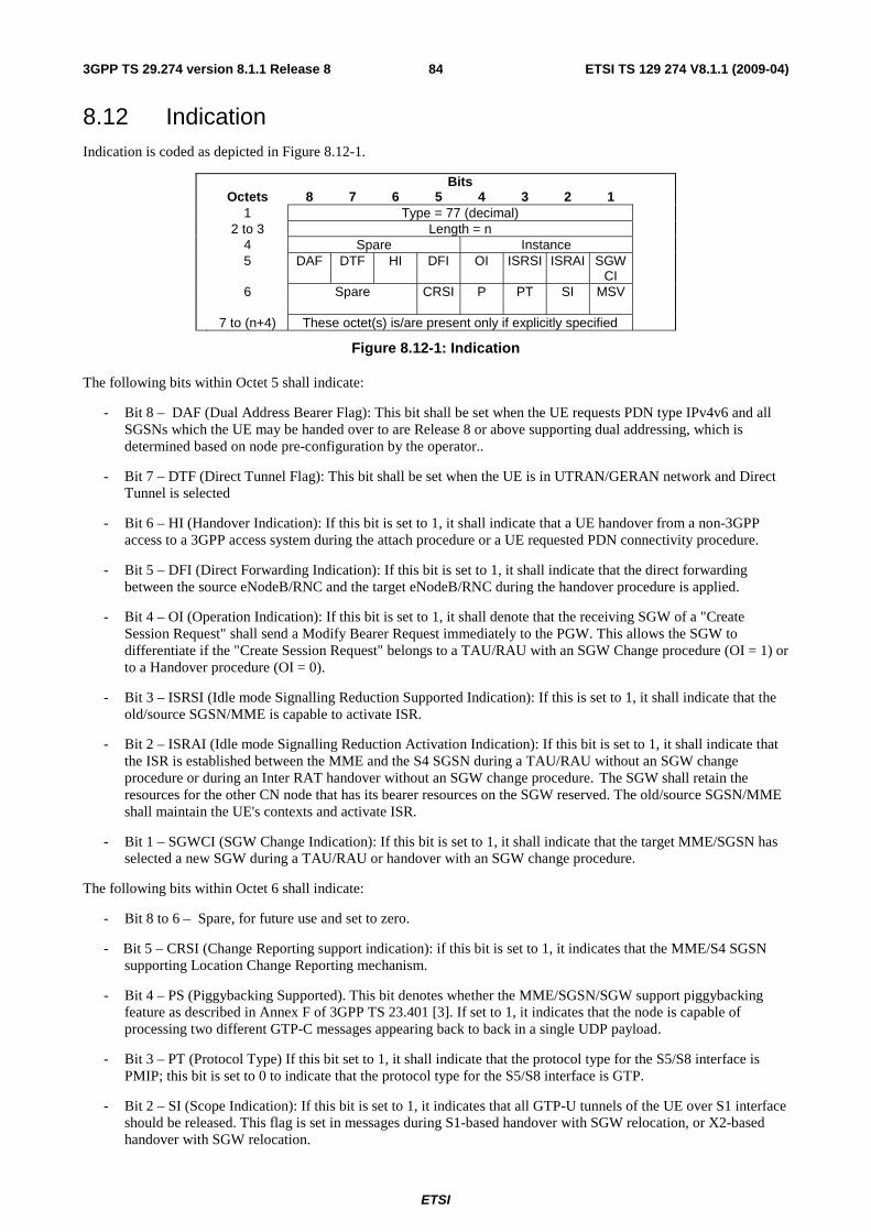
ETSI
ETSI TS 129 274 V8.1.1 (2009-04) 843GPP TS 29.274 version 8.1.1 Release 8
8.12 Indication Indication is coded as depicted in Figure 8.12-1.
Bits Octets 8 7 6 5 4 3 2 1 1 Type = 77 (decimal) 2 to 3 Length = n 4 Spare Instance 5 DAF DTF HI DFI OI ISRSI ISRAI SGW
CI
6 Spare
CRSI P PT SI MSV
7 to (n+4) These octet(s) is/are present only if explicitly specified
Figure 8.12-1: Indication
The following bits within Octet 5 shall indicate:
- Bit 8 – DAF (Dual Address Bearer Flag): This bit shall be set when the UE requests PDN type IPv4v6 and all SGSNs which the UE may be handed over to are Release 8 or above supporting dual addressing, which is determined based on node pre-configuration by the operator..
- Bit 7 – DTF (Direct Tunnel Flag): This bit shall be set when the UE is in UTRAN/GERAN network and Direct Tunnel is selected
- Bit 6 – HI (Handover Indication): If this bit is set to 1, it shall indicate that a UE handover from a non-3GPP access to a 3GPP access system during the attach procedure or a UE requested PDN connectivity procedure.
- Bit 5 – DFI (Direct Forwarding Indication): If this bit is set to 1, it shall indicate that the direct forwarding between the source eNodeB/RNC and the target eNodeB/RNC during the handover procedure is applied.
- Bit 4 – OI (Operation Indication): If this bit is set to 1, it shall denote that the receiving SGW of a "Create Session Request" shall send a Modify Bearer Request immediately to the PGW. This allows the SGW to differentiate if the "Create Session Request" belongs to a TAU/RAU with an SGW Change procedure (OI = 1) or to a Handover procedure (OI = 0).
- Bit 3 – ISRSI (Idle mode Signalling Reduction Supported Indication): If this is set to 1, it shall indicate that the old/source SGSN/MME is capable to activate ISR.
- Bit 2 – ISRAI (Idle mode Signalling Reduction Activation Indication): If this bit is set to 1, it shall indicate that the ISR is established between the MME and the S4 SGSN during a TAU/RAU without an SGW change procedure or during an Inter RAT handover without an SGW change procedure. The SGW shall retain the resources for the other CN node that has its bearer resources on the SGW reserved. The old/source SGSN/MME shall maintain the UE's contexts and activate ISR.
- Bit 1 – SGWCI (SGW Change Indication): If this bit is set to 1, it shall indicate that the target MME/SGSN has selected a new SGW during a TAU/RAU or handover with an SGW change procedure.
The following bits within Octet 6 shall indicate:
- Bit 8 to 6 – Spare, for future use and set to zero.
- Bit 5 – CRSI (Change Reporting support indication): if this bit is set to 1, it indicates that the MME/S4 SGSN supporting Location Change Reporting mechanism.
- Bit 4 – PS (Piggybacking Supported). This bit denotes whether the MME/SGSN/SGW support piggybacking feature as described in Annex F of 3GPP TS 23.401 [3]. If set to 1, it indicates that the node is capable of processing two different GTP-C messages appearing back to back in a single UDP payload.
- Bit 3 – PT (Protocol Type) If this bit set to 1, it shall indicate that the protocol type for the S5/S8 interface is PMIP; this bit is set to 0 to indicate that the protocol type for the S5/S8 interface is GTP.
- Bit 2 – SI (Scope Indication): If this bit is set to 1, it indicates that all GTP-U tunnels of the UE over S1 interface should be released. This flag is set in messages during S1-based handover with SGW relocation, or X2-based handover with SGW relocation.

ETSI
ETSI TS 129 274 V8.1.1 (2009-04) 853GPP TS 29.274 version 8.1.1 Release 8
- Bit 1 – MSV (MS Validated): If this bit is set to 1, it shall indicate that the new MME/SGSN has successfully authenticated the UE.
8.13 Protocol Configuration Options (PCO) Protocol Configuration Options (PCO) is transferred via GTP tunnels. The sending entity copies the value part of the PCO into the Value field of the PCO IE.
Editor's note: PCO will be defined in 3GPP TS 23.003 and its coding in TS 24.301.
Bits Octets 8 7 6 5 4 3 2 1 1 Type = 78 (decimal) 2 to 3 Length = n 4 Spare Instance 5 to (n+4) Protocol Configuration Options (PCO)
Figure 8.13-1: Protocol Configuration Options (PCO)
8.14 PDN Address Allocation (PAA) The PDN Address Allocation is coded as depicted in Figure 8.14-1.
NOTE: In Rel 8, Prefix length has a fixed value of /64.
Bits Octets 8 7 6 5 4 3 2 1 1 Type = 79 (decimal) 2 to 3 Length = n 4 Spare Instance 5 Spare PDN Type 6 to (n+4) PDN Address and Prefix
Figure 8.14-1: PDN Address Allocation (PAA)
Table 8.14-1: PDN Address Allocation
PDN type value (octet 5) Bits 3 2 1 0 0 1 IPv4 0 1 0 IPv6 0 1 1 IPv4/IPv6 Bits 8-4 of octet 5 are spare and shall be coded as zero. PDN Address and Prefix (octet 6 to n+4) If PDN type value indicates IPv4, an IPv4 address is present in the PDN Address and Prefix from octet 6 to octet 9. Bit 8 of octet 6 represents the most significant bit of the IPv4 address and bit 1 of octet 9 the least significant bit. If PDN type value indicates IPv6, octet 6 contains the IPv6 Prefix Length. Octets 7 through 22 contain an IPv6 address. Bit 8 of octet 7 represents the most significant bit of the IPv6 address and bit 1 of octet 22 the least significant bit. If PDN type value indicates IPv4/IPv6, octet 6 contains the IPv6 Prefix Length. Octets 7 through 22 contain an IPv6 address. Bit 8 of octet 7 represents the most significant bit of the IPv6 address and bit 1 of octet 22 the least significant bit. Octets 23 through 26 contain an IPv4 address. Bit 8 of octet 23 represents the most significant bit of the IPv4 address and bit 1 of octet 26 the least significant bit.

ETSI
ETSI TS 129 274 V8.1.1 (2009-04) 863GPP TS 29.274 version 8.1.1 Release 8
8.15 Bearer Quality of Service (Bearer QoS) Bearer Quality of Service (Bearer QoS) is transferred via GTP tunnels. The sending entity copies the value part of the Bearer l QoS into the Value field of the Bearer QoS IE.
Bits Octets 8 7 6 5 4 3 2 1 1 Type = 80 (decimal) 2-3 Length = n 4 Spare Instance 5 ARP 6 Label (QCI) 7 to 11 Maximum bit rate for uplink 12 to 16 Maximum bit rate for downlink 17 to 21 Guaranteed bit rate for uplink 22 to 26 Guaranteed bit rate for downlink 27 to (n+4) These octet(s) is/are present only if explicitly specified
Figure 8.15-1: Bearer Level Quality of Service (Bearer QoS)
ARP shall be specified in 3GPP TS 36.413 [10].
QCI, Maximum bit rate for uplink, Maximum bit rate for downlink, Guaranteed bit rate for uplink and Guaranteed bit rate for downlink are specified in 3GPP TS 36.413 [10]
The MBR and GBR are encoded as bits per second. For non-GBR bearers, both the UL/DL MBR and GBR should be set to zero.
NOTE: The encoding in 3GPP TS 24.301 [23] is different from the encoding here.
8.16 Flow Quality of Service (Flow QoS) Flow Quality of Service (Flow QoS) is transferred via GTP tunnels. The sending entity copies the value part of the
Flow QoS into the Value field of the Flow QoS IE.
Bits Octets 8 7 6 5 4 3 2 1 1 Type = 81 (decimal) 2 to 3 Length = n 4 Spare Instance 5 Label (QCI) 6 to 10 Maximum bit rate for uplink 11 to 15 Maximum bit rate for downlink 16 to 20 Guaranteed bit rate for uplink 21 to 25 Guaranteed bit rate for downlink 26 to (n+4) These octet(s) is/are present only if explicitly specified
Figure 8.16-1: Flow Quality of Service (Flow QoS)
QCI, Maximum bit rate for uplink, Maximum bit rate for downlink, Guaranteed bit rate for uplink and Guaranteed bit rate for downlink are specified in 3GPP TS 36.413 [10].
The MBR and GBR are encoded as bits per second. For non-GBR bearers, both the UL/DL MBR and GBR should be set to zero.
NOTE: The encoding in 3GPP TS 24.301 [23] is different from the encoding here.
8.17 RAT Type RAT Type is coded as depicted in Figure 8.17-1.

ETSI
ETSI TS 129 274 V8.1.1 (2009-04) 873GPP TS 29.274 version 8.1.1 Release 8
Bits Octets 8 7 6 5 4 3 2 1 1 Type = 82 (decimal) 2 to 3 Length = 1 4 Spare Instance 5 RAT Type 6 to (n+4) These octet(s) is/are present only if explicitly specified
Figure 8.17-1: RAT Type
Editor's note: RAT Type value range 1-255 is sufficient and extensions are not necessary.
Table 8.17-1: RAT Type values
RAT Types Values (Decimal) <reserved> 0
UTRAN 1 GERAN 2 WLAN 3 GAN 4
HSPA Evolution 5 EUTRAN 6 <spare> 7-255
Editor's note: Spare values 7-255 will be used for other RAT Type definitions (e.g. other non-3GPP accesses).
8.18 Serving Network Serving Network is coded as depicted in Figure 8.18-1.
Bits Octets 8 7 6 5 4 3 2 1 1 Type = 83 (decimal) 2 to 3 Length = n 4 Spare Instance 5 MCC digit 2 MCC digit 1 6 MNC digit 3 MCC digit 3 7 MNC digit 2 MNC digit 1 8 to (n+4) These octet(s) is/are present only if explicitly specified
Figure 8.18-1: Serving Network
If an Administration decides to include only two digits in the MNC, then bits 5 to 8 of octet 6 are coded as "1111".
8.19 EPS Bearer Level Traffic Flow Template (Bearer TFT) EPS Bearer Level Traffic Flow Template (Bearer TFT) is transferred via GTP tunnels. The sending entity copies the value part of the EPS Bearer Level TFT into the Value field of the EPS Bearer Level TFT IE.
Editor's note: EPS Bearer Level TFT will be defined in 3GPP TS 23.003 and its coding in TS 24.301.
Editor's note: It is FFS whether it needs two separate IE types for EPS Bearer Level TFT and SDF Level TFT.
Bits Octets 8 7 6 5 4 3 2 1 1 Type = 84 (decimal) 2 to 3 Length = n 4 Spare Instance 5 to (n+4) EPS Bearer Level Traffic Flow Template (TFT)
Figure 8.19-1: EPS Bearer Level Traffic Flow Template (Bearer TFT)

ETSI
ETSI TS 129 274 V8.1.1 (2009-04) 883GPP TS 29.274 version 8.1.1 Release 8
8.20 Traffic Aggregate Description (TAD) The Traffic Aggregate Description IE is coded as depicted in Figure 8.20-1. The detailed coding of Traffic Aggregate Description is specified in 3GPP TS 24.008 [5] , clause 10.5.6.12, beginning with octet 3..
Bits Octets 8 7 6 5 4 3 2 1 1 Type = 85 (Decimal) 2 to 3 Length = n 4 Spare Instance 5 to (n+4) Traffic Aggregate Description
Figure 8.20-1 Traffic Aggregate Description
8.21 User Location Info (ULI) User Location Info (ULI) is coded as depicted in Figure 8.21-1.
Bits Octets 8 7 6 5 4 3 2 1 1 Type = 86 (decimal) 2 to 3 Length = n 4 Spare Instance 5 Spare ECGI TAI RAI SAI CGI CGI SAI RAI TAI x to (n+4) ECGI
Figure 8.21-1: User Location Info
The flags ECGI, TAI, RAI, SAI and CGI in octet 5 indicate if the corresponding fields are present in the IE or not. If one of these flags is set to "0", the corresponding field is not present at all. The respective identities are defined in 3GPP TS 23.003 [2].
The following subclauses specify the coding of the different identities.
For each identity, if an Administration decides to include only two digits in the MNC, then bits 5 to 8 of octet 7 are coded as "1111".
8.21.1 CGI field
The coding of CGI (Cell Global Identifier) is depicted in Figure 8.21.1-1.
Bits Octets 8 7 6 5 4 3 2 1 1 Type = 86 (decimal) 2 to 3 Length = n 4 Spare Instance 5 Spare ECGI TAI RAI SAI CGI 6 MCC digit 2 MCC digit 1 7 MNC digit 3 MCC digit 3 8 MNC digit 2 MNC digit 1 9 to 10 Location Area Code (LAC) 11 to 12 Cell Identity (CI)
Figure 8.21.1-1: CGI
The Location Area Code (LAC) consists of 2 octets. Bit 8 of Octet 9 is the most significant bit and bit 1 of Octet 10 the least significant bit. The coding of the location area code is the responsibility of each administration. Coding using full hexadecimal representation shall be used.

ETSI
ETSI TS 129 274 V8.1.1 (2009-04) 893GPP TS 29.274 version 8.1.1 Release 8
The Cell Identity (CI) consists of 2 octets. Bit 8 of Octet 11 is the most significant bit and bit 1 of Octet 12 the least significant bit. The coding of the cell identity is the responsibility of each administration. Coding using full hexadecimal representation shall be used.
8.21.2 SAI field
The coding of SAI (Service Area Identifier) is depicted in Figure 8.21.2-1.
Bits Octets 8 7 6 5 4 3 2 1 1 Type = 86 (decimal) 2 to 3 Length = n 4 Spare Instance 5 Spare ECGI TAI RAI SAI CGI 6 MCC digit 2 MCC digit 1 7 MNC digit 3 MCC digit 3 8 MNC digit 2 MNC digit 1 9 to 10 Location Area Code (LAC) 11 to 12 Service Area Code (SAC)
Figure 8.21.2-1: SAI
The Location Area Code (LAC) consists of 2 octets. Bit 8 of Octet 9 is the most significant bit and bit 1 of Octet 10 the least significant bit. The coding of the location area code is the responsibility of each administration. Coding using full hexadecimal representation shall be used.
The Service Area Code (SAC) consists of 2 octets. Bit 8 of Octet 11 is the most significant bit and bit 1 of Octet 12 the least significant bit. The SAC is defined by the operator. See 3GPP TS 23.003 [2] section 12.5 for more information.
8.21.3 RAI field
The coding of RAI (Routing Area Identity) is depicted in Figure 8.21.3-1
Bits Octets 8 7 6 5 4 3 2 1 1 Type = 86 (decimal) 2 to 3 Length = n 4 Spare Instance 5 Spare ECGI TAI RAI SAI CGI 6 MCC digit 2 MCC digit 1 7 MNC digit 3 MCC digit 3 8 MNC digit 2 MNC digit 1 9 to 10 Location Area Code (LAC) 11 to 12 Routing Area Code (RAC)
Figure 8.21.3-1: RAI
The Location Area Code (LAC) consists of 2 octets. Bit 8 of Octet 9 is the most significant bit and bit 1 of Octet 10 the least significant bit. The coding of the location area code is the responsibility of each administration. Coding using full hexadecimal representation shall be used.
The Routing Area Code (RAC) consists of 2 octets. Only Octet 11 contains the RAC. Octet 12 is coded as all 1's (11111111). The RAC is defined by the operator.
8.21.4 TAI field
The coding of TAI (Tracking Area Identity) is depicted in Figure 8.21.4-1..

ETSI
ETSI TS 129 274 V8.1.1 (2009-04) 903GPP TS 29.274 version 8.1.1 Release 8
Bits Octets 8 7 6 5 4 3 2 1 1 Type = 86 (decimal) 2 to 3 Length = n 4 Spare Instance 5 Spare ECGI TAI RAI SAI CGI 6 MCC digit 2 MCC digit 1 7 MNC digit 3 MCC digit 3 8 MNC digit 2 MNC digit 1 9 to 10 Tracking Area Code (TAC)
Figure 8.21.4-1: TAI
The Tracking Area Code (TAC) consists of 2 octets. Bit 8 of Octet 9 is the most significant bit and bit 1 of Octet 10 the least significant bit. The coding of the tracking area code is the responsibility of each administration. Coding using full hexadecimal representation shall be used.
8.21.5 ECGI field
The coding of ECGI (E-UTRAN Cell Global Identifier) is depicted in Figure 8.21.5-1.
Bits Octets 8 7 6 5 4 3 2 1 1 Type = 86 (decimal) 2 to 3 Length = n 4 Spare Instance 5 Spare ECGI TAI RAI SAI CGI 6 MCC digit 2 MCC digit 1 7 MNC digit 3 MCC digit 3 8 MNC digit 2 MNC digit 1 9 Spare ECI 10 to 11 ECI (E-UTRAN Cell Identifier)
Figure 8.21.5-1: ECGI
The E-UTRAN Cell Identifier (ECI) consists of 28 bits. Bit 4 of octet 10 is the most significant bit and bit 1 of Octet 11 the least significant bit. The coding of the E-UTRAN cell identifier is the responsibility of each administration. Coding using full hexadecimal representation shall be used.
8.22 Fully Qualified TEID (F-TEID) Fully Qualified Tunnel Endpoint Identifier (F-TEID) is coded as depicted in Figure 8.22-1.
Bits Octets 8 7 6 5 4 3 2 1 1 Type = 87 (decimal) 2to 3 Length = n 4 Spare Instance 5 V4 V6 Spare Interface type 6 to 9 TEID / GRE Key m to (m+3) IPv4 address p to (p+15) IPv6 address k to (n+4) These octet(s) is/are present only if explicitly specified
Figure 8.22-1: Fully Qualified Tunnel Endpoint Identifier (F-TEID)
The following flags are coded within Octet 5:
- Bit 8 – V4: If this bit is set to "1", then IPv4 address field exists in the F-TEID, otherwise the IPv4 address field is not present at all.
- Bit 7 – V6: If this bit is set to "1", then IPv6 address field exists in the F-TEID, otherwise the IPv6 address field is not present at all.

ETSI
ETSI TS 129 274 V8.1.1 (2009-04) 913GPP TS 29.274 version 8.1.1 Release 8
At least one of V4 and V6 must be set to "1", and both may be set to "1".
- Bit 6 – Spare, shall be set to zero by the sender and ignored by the receiver.
- Bit 5 to Bit 1 – Interface Type: This 5 bit wide integer can take the following values representing interface type and endpoint:.
0 S1-U eNodeB GTP-U interface
1 S1-U SGW GTP-U interface
2 S12 RNC GTP-U interface
3 S12 SGW GTP-U interface
4 S5/S8 SGW GTP-U interface
5 S5/S8 PGW GTP-U interface
6 S5/S8 SGW GTP-C interface
7 S5/S8 PGW GTP-C interface
8 S5/S8 SGW PMIPv6 interface (the 32 bit GRE key is encoded in 32 bit TEID field and since alternate CoA is not used the control plane and user plane addresses are the same for PMIPv6)
9 S5/S8 PGW PMIPv6 interface (the 32 bit GRE key is encoded in 32 bit TEID field and the control plane and user plane addresses are the same for PMIPv6)
10 S11 MME GTP-C interface
11 S11/S4 SGW GTP-C interface
12 S10 MME GTP-C interface
13 S3 MME GTP-C interface
14 S3 SGSN GTP-C interface
15 S4 SGSN GTP-U interface
16 S4 SGW GTP-U interface
17 S4 SGSN GTP-C interface
18 S16 SGSN GTP-C interface
19 eNodeB GTP-U interface for DL data forwarding
20 eNodeB GTP-U interface for UL data forwarding
21 RNC GTP-U interface for data forwarding
22 SGSN GTP-U interface for data forwarding
23 SGW GTP-U interface for data forwarding
Other values of "Interface Type" are spare and reserved for future use
8.23 TMSI The TMSI, unambiguously associated with a given UE and Location area, is given by:

ETSI
ETSI TS 129 274 V8.1.1 (2009-04) 923GPP TS 29.274 version 8.1.1 Release 8
Bits Octets 8 7 6 5 4 3 2 1 1 Type = 88 (decimal) 2 to 3 Length = n 4 Spare Instance 5 to (n+4) TMSI
The TMSI is defined in 3GPP TS 23.003 [2].
Figure 8.23-1: TMSI
8.24 Global CN-Id The Global CN-Id is coded as depicted in Figure 8.24-1.
Bits Octets 8 7 6 5 4 3 2 1 1 Type = 89 (decimal) 2 to 3 Length = n 4 Spare Instance 5 MCC digit 2 MCC digit 1 6 MNC digit 3 MCC digit 3 7 MNC digit 2 MNC digit 1 8 to (n+4) CN-Id
The CN-Id is defined in 3GPP TS 23.003 [2].
Figure 8.24-1: Global CN-Id
If an Administration decides to include only two digits in the MNC, then bits 5 to 8 of octet 6 are coded as "1111".
8.25 S103 PDN Data Forwarding Info (S103PDF) The HSGWAddress and GRE Key identify a GRE Tunnel towards a HSGW over S103 interface for a specific PDN connection of the UE. The EPS Bearer IDs specify the EPS Bearers which require data forwarding that belonging to this PDN connection. The number of EPS bearer Ids included is specified by the value of EPS Bearer ID Number.
The spare bits indicate unused bits, which shall be set to 0 by the sending side and which shall not be evaluated by the receiving side.
Bits Octets 8 7 6 5 4 3 2 1 1 Type = 90 (decimal) 2 to 3 Length = n 4 Spare Instance 5 HSGW Address for forwarding Length = m 6 to (m+5) HSGW Address for forwarding [4..16] (m+6)- to
(m+9) GRE Key
(m+10) EPS Bearer ID Number = k (m+11) to
(m+10+k) Spare EPS Bearer ID
Figure 8.25-1: S103 PDN Data Forwarding Info
8.26 S1-U Data Forwarding (S1UDF) The Serving GW Address and Serving GW S1-U TEID consisit the S1-U Tunnel information allocated by the Serving GW for an EPS Bearer identified by the EPS Bearer ID which requires data forwarding during active handover from E-UTRAN Access to cdma2000 HRPD Access.
The spare bits indicate unused bits, which shall be set to 0 by the sending side and which shall not be evaluated by the receiving side.

ETSI
ETSI TS 129 274 V8.1.1 (2009-04) 933GPP TS 29.274 version 8.1.1 Release 8
Bits Octets 8 7 6 5 4 3 2 1 1 Type = 91 (decimal) 2 to 3 Length = n 4 Spare Instance 5 Spare EPS Bearer ID 6 Serving GW Address Length = m 7 to (m+6) These octet(s) is/are present only if explicitly specified (m+7) to
(m+10) Serving GW S1-U TEID
Figure 8.26-1: S1-U Data Forwarding Info
8.27 Delay Value Delay Value is coded as depicted in Figure 8.27-1.
Bits Octets 8 7 6 5 4 3 2 1 1 Type = 92 (decimal) 2 to 3 Length = n 4 Spare Instance 5 Delay Value in integer multiples of 50 millisecs, or zero 6 to (n+4) These octet(s) is/are present only if explicitly specified
Figure 8.27-1: Delay Value
Delay Value is set to zero in order to clear a previously set delay condition.
8.28 Bearer Context Bearer Context is a grouped IE containing a number of other IEs. Which of those IEs are mandatory, optional or conditional and the conditions that apply are GTP message specific, and described in the corresponding subclause under clause 7.
Bearer Context may be repeated within a message with exactly the same Type and Instance values to represent a list of Bearer Contexts.
Bearer Context is coded as depicted in Table 8.28-1.
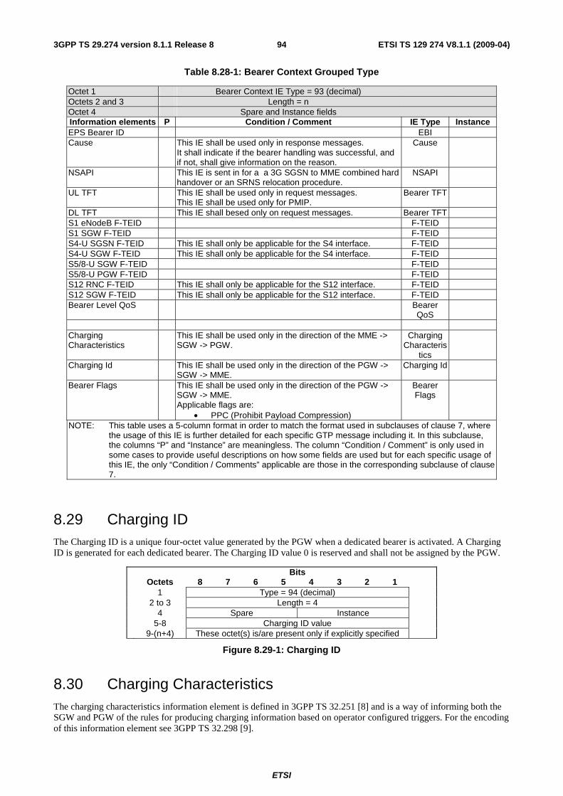
ETSI
ETSI TS 129 274 V8.1.1 (2009-04) 943GPP TS 29.274 version 8.1.1 Release 8
Table 8.28-1: Bearer Context Grouped Type
Octet 1 Bearer Context IE Type = 93 (decimal) Octets 2 and 3 Length = n Octet 4 Spare and Instance fields Information elements P Condition / Comment IE Type Instance EPS Bearer ID EBI Cause This IE shall be used only in response messages.
It shall indicate if the bearer handling was successful, and if not, shall give information on the reason.
Cause
NSAPI This IE is sent in for a a 3G SGSN to MME combined hard handover or an SRNS relocation procedure.
NSAPI
UL TFT This IE shall be used only in request messages. This IE shall be used only for PMIP.
Bearer TFT
DL TFT This IE shall besed only on request messages. Bearer TFT S1 eNodeB F-TEID F-TEID S1 SGW F-TEID F-TEID S4-U SGSN F-TEID This IE shall only be applicable for the S4 interface. F-TEID S4-U SGW F-TEID This IE shall only be applicable for the S4 interface. F-TEID S5/8-U SGW F-TEID F-TEID S5/8-U PGW F-TEID F-TEID S12 RNC F-TEID This IE shall only be applicable for the S12 interface. F-TEID S12 SGW F-TEID This IE shall only be applicable for the S12 interface. F-TEID Bearer Level QoS Bearer
QoS
Charging Characteristics
This IE shall be used only in the direction of the MME -> SGW -> PGW.
Charging Characteris
tics
Charging Id This IE shall be used only in the direction of the PGW -> SGW -> MME.
Charging Id
Bearer Flags This IE shall be used only in the direction of the PGW -> SGW -> MME. Applicable flags are:
• PPC (Prohibit Payload Compression)
Bearer Flags
NOTE: This table uses a 5-column format in order to match the format used in subclauses of clause 7, where the usage of this IE is further detailed for each specific GTP message including it. In this subclause, the columns “P” and “Instance” are meaningless. The column “Condition / Comment” is only used in some cases to provide useful descriptions on how some fields are used but for each specific usage of this IE, the only “Condition / Comments” applicable are those in the corresponding subclause of clause 7.
8.29 Charging ID The Charging ID is a unique four-octet value generated by the PGW when a dedicated bearer is activated. A Charging ID is generated for each dedicated bearer. The Charging ID value 0 is reserved and shall not be assigned by the PGW.
Bits Octets 8 7 6 5 4 3 2 1 1 Type = 94 (decimal) 2 to 3 Length = 4 4 Spare Instance 5-8 Charging ID value 9-(n+4) These octet(s) is/are present only if explicitly specified
Figure 8.29-1: Charging ID
8.30 Charging Characteristics The charging characteristics information element is defined in 3GPP TS 32.251 [8] and is a way of informing both the SGW and PGW of the rules for producing charging information based on operator configured triggers. For the encoding of this information element see 3GPP TS 32.298 [9].
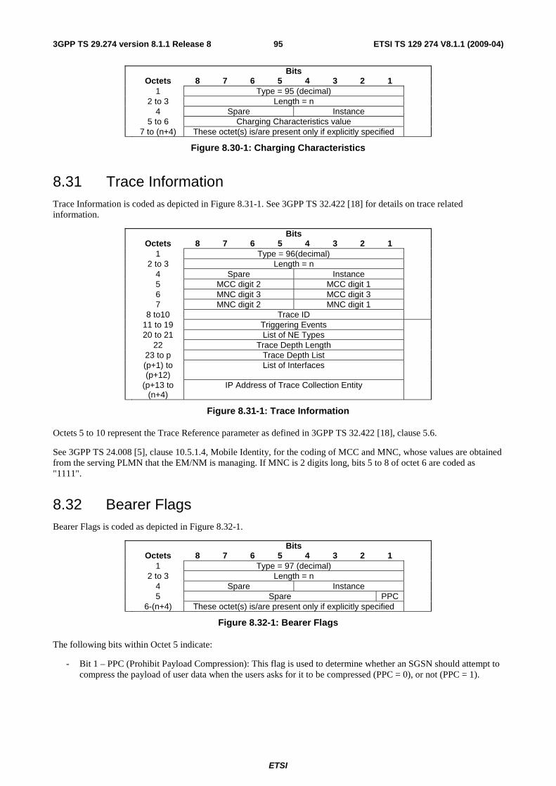
ETSI
ETSI TS 129 274 V8.1.1 (2009-04) 953GPP TS 29.274 version 8.1.1 Release 8
Bits Octets 8 7 6 5 4 3 2 1 1 Type = 95 (decimal) 2 to 3 Length = n 4 Spare Instance 5 to 6 Charging Characteristics value 7 to (n+4) These octet(s) is/are present only if explicitly specified
Figure 8.30-1: Charging Characteristics
8.31 Trace Information Trace Information is coded as depicted in Figure 8.31-1. See 3GPP TS 32.422 [18] for details on trace related information.
Bits Octets 8 7 6 5 4 3 2 1 1 Type = 96(decimal) 2 to 3 Length = n 4 Spare Instance 5 MCC digit 2 MCC digit 1 6 MNC digit 3 MCC digit 3 7 MNC digit 2 MNC digit 1 8 to10 Trace ID 11 to 19 Triggering Events 20 to 21 List of NE Types 22 Trace Depth Length 23 to p Trace Depth List (p+1) to
(p+12) List of Interfaces
(p+13 to (n+4)
IP Address of Trace Collection Entity
Figure 8.31-1: Trace Information
Octets 5 to 10 represent the Trace Reference parameter as defined in 3GPP TS 32.422 [18], clause 5.6.
See 3GPP TS 24.008 [5], clause 10.5.1.4, Mobile Identity, for the coding of MCC and MNC, whose values are obtained from the serving PLMN that the EM/NM is managing. If MNC is 2 digits long, bits 5 to 8 of octet 6 are coded as "1111".
8.32 Bearer Flags Bearer Flags is coded as depicted in Figure 8.32-1.
Bits Octets 8 7 6 5 4 3 2 1 1 Type = 97 (decimal) 2 to 3 Length = n 4 Spare Instance 5 Spare PPC 6-(n+4) These octet(s) is/are present only if explicitly specified
Figure 8.32-1: Bearer Flags
The following bits within Octet 5 indicate:
- Bit 1 – PPC (Prohibit Payload Compression): This flag is used to determine whether an SGSN should attempt to compress the payload of user data when the users asks for it to be compressed (PPC = 0), or not (PPC = 1).

ETSI
ETSI TS 129 274 V8.1.1 (2009-04) 963GPP TS 29.274 version 8.1.1 Release 8
8.33 Paging Cause Paging Cause is transferred from the SGW to MME across S11 so it can then be passed to the eNodeB over S1AP in the Paging message as specified in 3GPP TS 36.413 [10].
The Paging Cause is coded as shown in Figure 8.33-1.
Bits Octets 8 7 6 5 4 3 2 1 1 Type = 98 (decimal) 2 to 3 Length = n 4 Spare Instance 5 to (n+4) Paging Cause value
Figure 8.33-1: Paging Cause
8.34 PDN Type The PDN Type is coded as depicted in Figure 8.34-1.
Bits Octets 8 7 6 5 4 3 2 1 1 Type = 99 (decimal) 2 to 3 Length = n 4 Spare Instance 5 Spare PDN Type 6 to n+4) These octet(s) is/are present only if explicitly specified
Figure 8.34-1: PDN Type
Table 8.34-1: PDN Type
PDN type value (octet 5) Bits 3 2 1 0 0 1 IPv4 0 1 0 IPv6 0 1 1 IPv4/IPv6 Bits 8-4 of octet 5 are spare and shall be coded as zero.
8.35 Procedure Transaction ID (PTI) Procedure Transaction Id is coded as depicted in Figure 8.35-1.
Bits Octets 8 7 6 5 4 3 2 1 1 Type = 100 (decimal) 2 to 3 Length = n 4 Spare Instance 5 Procedure Transaction ID 6 to (n+4) These octet(s) is/are present only if explicitly specified
Figure 8.35-1: Procedure Transaction ID
8.36 DRX Parameter DRX Parameter indicates whether the UE use DRX mode or not, this parameter is coded as depicted in Figure 839-1.

ETSI
ETSI TS 129 274 V8.1.1 (2009-04) 973GPP TS 29.274 version 8.1.1 Release 8
Bits Octets 8 7 6 5 4 3 2 1 1 Type = 101 (decimal) 2 to 3 Length = n 4 Spare Instance 5 to (n+4) DRX Parameter
Figure 8.36-1: DRX Parameter
8.37 UE Network Capability UE Network Capability is coded as depicted in Figure 8.37-1. Actual coding of the UE Network Capability field is defined in 3GPP TS 24.301 [23].
Bits Octets 8 7 6 5 4 3 2 1 1 Type = 102 (decimal) 2 to 3 Length = n 4 Spare Instance 5 to (n+4) UE Network Capability
Figure 8.37-1: UE Network Capability
8.38 MM Context The MM Context information element contains the Mobility Management, UE security parameters that are necessary to transfer over S3/S16/S10 interface.
All Spare bits are set to zeros by the sender and ignored by the receiver. Spare bits in MM Context IE shall be set to 1's before sending MM Context IE to pre-R8 SGSN.
Security Mode indicates the type of security keys (GSM/UMTS/EPS) and Authentication Vectors (quadruplets /quintuplets/triplets) that are passed to the new MME/SGSN.
The DRX parameter coding is specified in clause 9.9.3.34 of 3GPP TS 24.008 [5]. If DRXI (DRX Indicator), bit 4 of octet 5, is set to "1", then the DRX parameter field is present, otherwise its octets are not present.
Uplink/downlink Subscribed UE AMBR (Aggregate Maximum Bit Rate) is coded as Unsigned32 integer values in Kbps for all non-GBR bearers according to the subscription of the user.
Uplink/downlink Used UE AMBR (Aggregate Maximum Bit Rate) is coded as Unsigned32 integer values in Kbps for all non-GBR bearers currently being used by the UE.
The Mobile Equipment Identity (MEI) is equal to either the IMEI or the IMEISV as specified in clause 10.5.1.4 of 3GPP TS 24.008 [5]. As defined in clause 6.2 of 3GPP TS 23.003 [2], IMEI is 15 BCD digits and IMEISV is 16 BCD digits.
The UE Network Capability coding is specified in clause 9.9.3.34 of 3GPP TS 24.301 [23]. If Length of UE Network Caapability is zero, then the UE Network Capability parameter shall not be present.
The MS Network Capability coding is specified in clause 10.5.5.12 of 3GPP TS 24.008 [5]. If Length of MS Network Caapability is zero, then the MS Network Capability parameter shall not be present.
Used Cipher indicates the GSM ciphering algorithm that is in use.
Used NAS Cipher indicates the EPS ciphering algorithm that is in use.
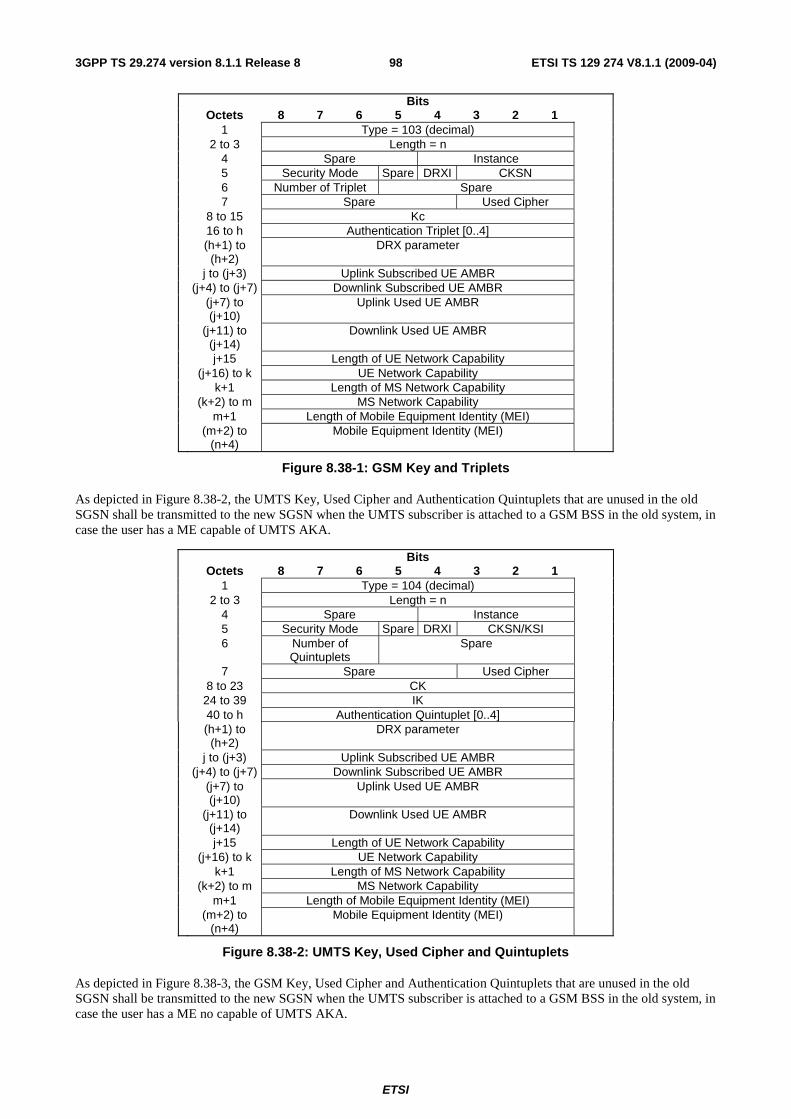
ETSI
ETSI TS 129 274 V8.1.1 (2009-04) 983GPP TS 29.274 version 8.1.1 Release 8
Bits Octets 8 7 6 5 4 3 2 1 1 Type = 103 (decimal) 2 to 3 Length = n 4 Spare Instance 5 Security Mode Spare DRXI CKSN 6 Number of Triplet Spare 7 Spare Used Cipher 8 to 15 Kc 16 to h Authentication Triplet [0..4] (h+1) to
(h+2) DRX parameter
j to (j+3) Uplink Subscribed UE AMBR (j+4) to (j+7) Downlink Subscribed UE AMBR (j+7) to
(j+10) Uplink Used UE AMBR
(j+11) to (j+14)
Downlink Used UE AMBR
j+15 Length of UE Network Capability (j+16) to k UE Network Capability k+1 Length of MS Network Capability (k+2) to m MS Network Capability m+1 Length of Mobile Equipment Identity (MEI) (m+2) to
(n+4) Mobile Equipment Identity (MEI)
Figure 8.38-1: GSM Key and Triplets
As depicted in Figure 8.38-2, the UMTS Key, Used Cipher and Authentication Quintuplets that are unused in the old SGSN shall be transmitted to the new SGSN when the UMTS subscriber is attached to a GSM BSS in the old system, in case the user has a ME capable of UMTS AKA.
Bits Octets 8 7 6 5 4 3 2 1 1 Type = 104 (decimal) 2 to 3 Length = n 4 Spare Instance 5 Security Mode Spare DRXI CKSN/KSI 6 Number of
Quintuplets Spare
7 Spare Used Cipher 8 to 23 CK 24 to 39 IK 40 to h Authentication Quintuplet [0..4] (h+1) to
(h+2) DRX parameter
j to (j+3) Uplink Subscribed UE AMBR (j+4) to (j+7) Downlink Subscribed UE AMBR (j+7) to
(j+10) Uplink Used UE AMBR
(j+11) to (j+14)
Downlink Used UE AMBR
j+15 Length of UE Network Capability (j+16) to k UE Network Capability k+1 Length of MS Network Capability (k+2) to m MS Network Capability m+1 Length of Mobile Equipment Identity (MEI) (m+2) to
(n+4) Mobile Equipment Identity (MEI)
Figure 8.38-2: UMTS Key, Used Cipher and Quintuplets
As depicted in Figure 8.38-3, the GSM Key, Used Cipher and Authentication Quintuplets that are unused in the old SGSN shall be transmitted to the new SGSN when the UMTS subscriber is attached to a GSM BSS in the old system, in case the user has a ME no capable of UMTS AKA.

ETSI
ETSI TS 129 274 V8.1.1 (2009-04) 993GPP TS 29.274 version 8.1.1 Release 8
Bits Octets 8 7 6 5 4 3 2 1 1 Type = 105 (decimal) 2 to 3 Length = n 4 Spare Instance 5 Security Mode Spare DRXI CKSN/KSI 6 Number of
Quintuplets Spare
7 Spare Used Cipher 8 to 15 Kc 16 to h Authentication Quintuplets [0..4] (h+1) to
(h+2) DRX parameter
j to (j+3) Uplink Subscribed UE AMBR (j+4) to (j+7) Downlink Subscribed UE AMBR (j+7) to
(j+10) Uplink Used UE AMBR
(j+11) to (j+14)
Downlink Used UE AMBR
j+15 Length of UE Network Capability (j+16) to k UE Network Capability k+1 Length of MS Network Capability (k+2) to m MS Network Capability m+1 Length of Mobile Equipment Identity (MEI) (m+2) to
(n+4) Mobile Equipment Identity (MEI)
Figure 8.38-3: GSM Key, Used Cipher and Quintuplets
As depicted in Figure 8.38-4, the UMTS Key, KSI and unused Authentication Quintuplets in the old SGSN shall be transmitted to the new SGSN/MME when the UMTS subscriber is attached to UTRAN in the old system.
Bits Octets 8 7 6 5 4 3 2 1 1 Type = 106 (decimal) 2 to 3 Length = n 4 Spare Instance 5 Security Mode Spare DRXI KSI 6 Number of
Quintuplets Spare
7 Spare 8 to 23 CK 24 to 39 IK 40 to h Authentication Quintuplet [0..4] (h+1) to
(h+2) DRX parameter
j to (j+3) Uplink Subscribed UE AMBR (j+4) to (j+7) Downlink Subscribed UE AMBR (j+7) to
(j+10) Uplink Used UE AMBR
(j+11) to (j+14)
Downlink Used UE AMBR
j+15 Length of UE Network Capability (j+16) to k UE Network Capability k+1 Length of MS Network Capability (k+2) to m MS Network Capability m+1 Length of Mobile Equipment Identity (MEI) (m+2) to
(n+4) Mobile Equipment Identity (MEI)
Figure 8.38-4: UMTS Key and Quintuplets
As depicted in Figure 8.38-5, the EPS Security Context, unused Authentication Quadruplets in the old MME shall be transmitted to the new MME. And the Authentication Quintuplets may also be transmitted to the new MME if the old MME has the Authentication Quintuplets for this UE.

ETSI
ETSI TS 129 274 V8.1.1 (2009-04) 1003GPP TS 29.274 version 8.1.1 Release 8
Bits Octets 8 7 6 5 4 3 2 1 1 Type = 107 (decimal) 2 to 3 Length = n 4 Spare Instance 5 Security Mode NHI DRXI KSIASME 6 Number of
Quintuplets Number of Quadruplet
Spare
7 Spare Used NAS integrity protection algorithm
Used NAS Cipher
8 to 10 NAS Downlink Count 11 to 13 NAS Uplink Count 14 to 45 KASME 46 to g Authentication Quadruplet [0..4] (g+1) to h Authentication Quintuplet [0..4] (h+1) to
(h+2) DRX parameter
p to (p+31) NH p+32 Spare NCC j to (j+3) Uplink Subscribed UE AMBR (j+4) to (j+7) Downlink Subscribed UE AMBR (j+7) to
(j+10) Uplink Used UE AMBR
(j+11) to (j+14)
Downlink Used UE AMBR
j+15 Length of UE Network Capability (j+16) to k UE Network Capability k+1 Length of MS Network Capability (k+2) to m MS Network Capability m+1 Length of Mobile Equipment Identity (MEI) (m+2) to
(n+4) Mobile Equipment Identity (MEI)
Figure 8.38-5: EPS Security Context, Quadruplets and Quintuplets
If NHI (Next Hop Indicator), bit 5 of octet 5, is set to "1", then the optional parameters NH (Next Hop) and NCC (Next Hop Chaining Count) are both present, otherwise their octets are not present.
NAS integrity protection algorithm shall be specified in 3GPP TS 24.301 [23].
As depicted in Figure 8.43-6, if the old MME has Authentication Quintuplets for this UE, the old MME will derive CK" and IK" from KASME and transmit the CK", IK", KSIASME and Authentication Quintuplets to the new SGSN, the Authentication Quadruplets may also be transmitted to the new SGSN.
Editor's Notes: the old SGSN/MME may delivery both Authentication Quadruplets and Authentication Quintuplets it holds to the peer combo node to optimize the procedure, the details need more clarification

ETSI
ETSI TS 129 274 V8.1.1 (2009-04) 1013GPP TS 29.274 version 8.1.1 Release 8
Bits Octets 8 7 6 5 4 3 2 1 1 Type = 108 (decimal) 2 to 3 Length = n 4 Spare Instance 5 Security Mode Spare DRXI KSIASME 6 Number of
Quintuplets Number of Quadruplet
Spare
7 Spare 8 to 23 CK 24 to 39 IK 40 to g Authentication Quadruplet [0..4] (g+1) to h Authentication Quintuplet [0..4] (h+1) to
(h+2) DRX parameter
j to (j+3) Uplink Subscribed UE AMBR (j+4) to (j+7) Downlink Subscribed UE AMBR (j+7) to
(j+10) Uplink Used UE AMBR
(j+11) to (j+14)
Downlink Used UE AMBR
j+15 Length of UE Network Capability (j+16) to k UE Network Capability k+1 Length of MS Network Capability (k+2) to m MS Network Capability m+1 Length of Mobile Equipment Identity (MEI) (m+2) to
(n+4) Mobile Equipment Identity (MEI)
Figure 8.38-6: UMTS Key, Quadruplets and Quintuplets
Table 8.38-1: Security Mode Values
Security Type Value (Decimal) GSM Key and Triplets 0 UMTS Key, Used Cipher and Quintuplets 1 GSM Key, Used Cipher and Quintuplets 2 UMTS Key and Quintuplets 3 EPS Security Context, Quadruplets and Quintuplets 4 UMTS Key, Quadruplets and Quintuplets 5
Table 8.38-2: Used NAS Cipher Values
Cipher Algorithm Value (Decimal) No ciphering 0 128-EEA1 1 128-EEA2 2
Table 8.38-3: Used Cipher Values
Cipher Algorithm Value (Decimal) No ciphering 0
GEA/1 1 GEA/2 2 GEA/3 3 GEA/4 4 GEA/5 5 GEA/6 6 GEA/7 7

ETSI
ETSI TS 129 274 V8.1.1 (2009-04) 1023GPP TS 29.274 version 8.1.1 Release 8
8.39 PDN Connection The PDN connection is a grouped IE containing a number of other IEs and shall be coded as depicted in Table 8.39-1. The APN IE directly follows octet 4.
The PDN Connection IE may be repeated within a message with exactly the same Type and Instance values to represent a list.
Table 8.39-1: PDN Connection Grouped Type
Octet 1 PDN Connection IE Type = 109 (decimal) Octets 2 and 3 Length = n Octet 4 Spare and Instance fields
Information elements
P Condition / Comment IE Type Instance
APN APN IPv4 Address This IE shall not be present if an IPv4 Address is not
assigned. IP Address
IPv6 Address This IE shall not be present if an IPv6 Address is not assigned
IP Address
Linked EPS Bearer Identity
This IE shall be included to identify the default bearer of the PDN Connection
EBI
PGW S5/S8 IP Address and TEID for Control Plane
This IE shall only be Included for GTP based S5/S8 F-TEID
PGW node name Includes the PGW FQDN FQDN Bearer Contexts Several IEs with these type and instance values may be
included as necessary to represent a list of Bearers. Bearer Context
Aggregate Maximum Bit Rate (APN-AMBR)
Includes the APN-AMBR. AMBR
NOTE: This table uses a 5-column format in order to match the format used in subclauses of clause 7, where the usage of this IE is further detailed for each specific GTP message including it. In this subclause, the columns “P” and “Instance” are meaningless. The column “Condition / Comment” is only used in some cases to provide useful descriptions on how some fields are used but for each specific usage of this IE, the only “Condition / Comments” applicable are those in the corresponding subclause of clause 7.
The Bearer Context shall be coded as depicted in Table 8.39-2.

ETSI
ETSI TS 129 274 V8.1.1 (2009-04) 1033GPP TS 29.274 version 8.1.1 Release 8
Table 8.39-2: Bearer Context in PDN Connection Grouped Type
Ocett 1 Bearer Context IE Type = 93 (decimal) Octets 2 and 3 Length = n Octet 4 Spare and Instance fields
Information elements
P Condition / Comment IE Type Instance
EPS Bearer ID EBI UL TFT Bearer TFT DL TFT Bearer TFT SGW S1/S4/S12 IP Address and TEID for user plane
F-TEID
PGW S5/S8 IP Address and TEID for user plane
This IE shall only be included for GTP based S5/S8 interfaces.
F-TEID
Bearer Level QoS Bearer QoS
Charging characteristics
Charging characterist
ics
Container The Packet Flow ID , Radio Priority, SAPI, PS Handover XID Parameters may be included as necessary.
Container
NOTE: This table uses a 5-column format in order to match the format used in subclauses of clause 7, where the usage of this IE is further detailed for each specific GTP message including it. In this subclause, the columns “P” and “Instance” are meaningless. The column “Condition / Comment” is only used in some cases to provide useful descriptions on how some fields are used but for each specific usage of this IE, the only “Condition / Comments” applicable are those in the corresponding subclause of clause 7.
8.40 PDU Numbers The PDU Numbers information element contains the sequence number status corresponding to a Bearer context in the old SGSN. This information element shall be sent only when acknowledged peer-to-peer LLC operation is used for the Bearer context or when the "delivery order" QoS attribute is set in the Bearer context QoS profile.
NSAPI identifies the Bearer context for which the PDU Number IE is intended.
DL GTP-U Sequence Number is the number for the next downlink GTP-U T-PDU to be sent to the UE when "delivery order" is set.
UL GTP-U Sequence Number is the number for the next uplink GTP-U T-PDU to be tunnelled to the S-GW when "delivery order" is set.
The Send N-PDU Number is used only when acknowledged peer-to-peer LLC operation is used for the Bearer context. Send N-PDU Number is the N-PDU number to be assigned by SNDCP to the next down link N-PDU received from the S-GW.
The Receive N-PDU Number is used only when acknowledged peer-to-peer LLC operation is used for the Bearer context. The Receive N-PDU Number is the N-PDU number expected by SNDCP from the next up link N-PDU to be received from the UE.
The PDU Number IE will be repeated for each Bearer Context for which this IE is required.
PDU Numbers IE is coded as depicted in Figure 8.40-1.

ETSI
ETSI TS 129 274 V8.1.1 (2009-04) 1043GPP TS 29.274 version 8.1.1 Release 8
Bits Octets 8 7 6 5 4 3 2 1
1 Type = 110 (decimal) 2 to 3 Length = n
4 Spare Instance 5 Spare(0 0 0 0) NSAPI
6-7 DL GTP-U Sequence Number 8-9 UL GTP-U Sequence Number
10-11 Send N-PDU Number 12-13 Receive N-PDU Number
14 to (n+4) These octet(s) is/are present only if explicitly specified
Figure 8.40-1: PDU Numbers
8.41 Packet TMSI (P-TMSI) The P-TMSI, unambiguously associated with a given UE and routeing area, is given by:
Bits Octets 8 7 6 5 4 3 2 1 1 Type = 111 (decimal) 2 to 3 Length = n 4 Spare Instance 5 to (n+4) Packet TMSI (P-TMSI)
The P-TMSI is defined in 3GPP TS 23.003 [2].
Figure 8.41-1: Packet TMSI (P-TMSI)
8.42 P-TMSI Signature The P-TMSI Signature information element is provided by the UE in the Routeing Area Update Request and Attach Request messages to the SGSN, or is provided by the MME that is mapped from GUTI in the Identification Request and Context Request messages to the old SGSN for identification checking purposes. The content and the coding of the P-TMSI Signature information element are defined in 3GPP TS 24.008 [5].
Bits Octets 8 7 6 5 4 3 2 1 1 Type = 112 (decimal) 2 to 3 Length = n 4 Spare Instance 5 to (n+4) P-TMSI Signature
Figure 8.42-1: P-TMSI Signature
8.43 Hop Counter Where Intra Domain Connection of RAN Nodes to Multiple CN Node is applied, the Hop Counter may be used to prevent endless loops when relaying Identification Request messages and Context Request messages. The maximum value is operator specific and shall not be lower than 1.
Bits Octets 8 7 6 5 4 3 2 1 1 Type = 113 (decimal) 2 to 3 Length = n 4 Spare Instance 5 Hop Counter 6 to (n+4) These octet(s) is/are present only if explicitly specified
Figure 8.43-1: Hop Counter

ETSI
ETSI TS 129 274 V8.1.1 (2009-04) 1053GPP TS 29.274 version 8.1.1 Release 8
8.44 UE Time Zone UE Time Zone is used to indicate the offset between universal time and local time in steps of 15 minutes of where the UE currently resides. The "Time Zone" field uses the same format as the "Time Zone" IE in 3GPP TS 24.008 [5].
UE Time Zone is coded as this is depicted in Figure 8.44-1.
The spare bits indicate unused bits, which shall be set to 0 by the sending side and which shall not be evaluated by the receiving side.
Bits Octets 8 7 6 5 4 3 2 1 1 Type = 114 (decimal) 2 to 3 Length = n 4 Spare Instance 5 Time Zone 6 Spare Daylight
Saving Time
7 to (n+4) These octet(s) is/are present only if explicitly specified
Figure 8.44-1: UE Time Zone
Table 8.44-2 Possible values for the "Daylight Saving Time" field and their meanings.
Value (binary) Daylight Saving Time Bit 2 Bit 1
No adjustment for Daylight Saving Time 0 0 +1 hour adjustment for Daylight Saving Time 0 1 +2 hours adjustment for Daylight Saving Time 1 0 Spare 1 1
8.45 Trace Reference Trace Reference shall be coded as depicted in Figure 8.45-1. See 3GPP TS 32.422 [18], clause 5.6, for the definition of Trace Reference.
See 3GPP TS 24.008 [5], clause 10.5.1.4, Mobile Identity, for the coding of MCC and MNC, whose values are obtained from the serving PLMN that the EM/NM is managing. If MNC is 2 digits long, bits 5 to 8 of octet 6 are coded as "1111".
Bits Octets 8 7 6 5 4 3 2 1 1 Type = 115 (decimal) 2 to 3 Length = 6 4 Spare Instance 5 MCC digit 2 MCC digit 1 6 MNC digit 3 MCC digit 3 7 MNC digit 2 MNC digit 1 8 to10 Trace ID
Figure 8.45-1: Trace Reference
8.46 Complete Request Message The Complete Request Message is coded as depicted in Figure 8.46-1.

ETSI
ETSI TS 129 274 V8.1.1 (2009-04) 1063GPP TS 29.274 version 8.1.1 Release 8
Bits Octets 8 7 6 5 4 3 2 1 1 Type = 116 (decimal) 2 to 3 Length = n 4 Spare Instance 5 Complete Request Message Type 6- to (n+4) Complete Request Message
Figure 8.46-1: Complete Request Message
Complete Request Message type values are specified in Table 8.46-1.
Table 8.46-1: Complete Request Message type values and their meanings
Location Types Values (Decimal) Complete Attach Request Message 0 Complete TAU Request Message 1
<spare> 2-255
8.47 GUTI The GUTI is coded as depicted in Figure 8.47-1.
Bits Octets 8 7 6 5 4 3 2 1 1 Type = 117 (decimal) 2 to 3 Length = n 4 Spare Instance 5 MCC digit 2 MCC digit1 6 MNC digit3 MCC digit3 7 MNC digit2 MNC digit1 8 to 9 MME Group ID 10 MME Code 11 to (n+4) M-TMSI
Figure 8.47-1: GUTI
If an Administration decides to include only two digits in the MNC, then bits 5 to 8 of octet 3 are coded as "1111".
8.48 Fully Qualified Container (F-Container) Fully Qualified Container (F-TEID) is coded as depicted in Figure 8.48-1.
All Spare bits are set to zeros by the sender and ignored by the receiver. Spare bits in F-Container IE shall be set to 1's before sending F-Container to pre-R8 SGSN.
Bits Octets 8 7 6 5 4 3 2 1 1 Type = 118 (decimal) 2 to 3 Length = n 4 Spare Instance 5 Spare Container Type 6 to (n+4) F-Container field
Figure 8.48-1: Full Qualified Container(F-Container)
The Container Type is coded as below:
- If this field is set to 1, then the F-Container field present the UTRAN transparent container.
- If this field is set to 2, then the F-Container field present the BSS container.
- If this field is set to 3, then the F-Container field present the E-UTRAN transparent container.

ETSI
ETSI TS 129 274 V8.1.1 (2009-04) 1073GPP TS 29.274 version 8.1.1 Release 8
8.49 Fully Qualified Cause (F-Cause) Fully Qualified Cause (F- Cause) is coded as depicted in Figure 8.49-1.
Bits Octets 8 7 6 5 4 3 2 1 1 Type = 119 (decimal) 2 to 3 Length = n 4 Spare Instance 5 to (n+4) F-Cause field
Figure 8.49-1: Full Qualified Cause (F-Cause)
8.50 Selected PLMN ID The Selected PLMN ID IE contains the core network operator selected for tne UE in a shared network. Octets 5-7 shall be encoded as the content part of the "Selected PLMN Identity" parameter in 3GPP TS 36.413 [10].
Bits Octets 8 7 6 5 4 3 2 1 1 Type = 120 (decimal) 2 to 3 Length = n 4 Spare Instance 5 to (n+4) Selected PLMN ID
Figure 8.50-1: Selected PLMN ID
8.51 Target Identification The Target Identification information element is coded as depicted in Figure 8.51-1. It contains the identification of a target RNC or a target eNodeB.
Bits Octets 8 7 6 5 4 3 2 1 1 Type = 121 (decimal) 2 to 3 Length = n 4 Spare Instance 5 Target Type 6 to (n+4) Target ID
Figure 8.51-1: Target Identification
Target Type values are specified in Table 8.51-1.
The Target Type is RNC ID for SRNS relocation procedure and handover to UTRAN.
The Target Type is eNodeB ID for handover to E-UTRAN.
Table 8.51-1: Target Type values and their meanings
Target Types Values (Decimal) RNC ID 0
eNodeB ID 1 Cell Identifier 2
<spare> 3 to 255
8.52 NSAPI The NSAPI information element contains an NSAPI identifying a PDP Context.

ETSI
ETSI TS 129 274 V8.1.1 (2009-04) 1083GPP TS 29.274 version 8.1.1 Release 8
All Spare bits are set to zeros by the sender and ignored by the receiver. Spare bits in F-Container IE shall be set to 1's before sending F-Container to pre-R8 SGSN.
Bits Octets 8 7 6 5 4 3 2 1 1 Type = 122 (decimal) 2 to 3 Length = n 4 Spare Instance 5 Spare NSAPI 6 to (n+4) These octet(s) is/are present only if explicitly specified
Figure 8.52-1: NSAPI
8.53 Packet Flow ID The Packet Flow Id information element contains the packet flow identifier assigned to a PDP context as identified by NSAPI.
The spare bits 8 to 5 in octet 5 indicate unused bits, which shall be set to 0 by the sending side and which shall not be evaluated by the receiving side.
Bits Octets 8 7 6 5 4 3 2 1 1 Type = 123 (decimal) 2 to 3 Length = n 4 Spare Instance 5 Spare NSAPI 6 to (n+4) Packet Flow ID
Figure 8.53-1: Packet Flow ID
8.54 RAB Context The RAB Context shall be coded as is depicted in Figure 8.54-1.
Bits Octets 8 7 6 5 4 3 2 1 1 Type = 124 (decimal) 2 to 3 Length = 8 4 Spare Instance 5 Spare NSAPI 6 to 7 DL GTP-U Sequence Number 8 to 9 UL GTP-U Sequence Number 9 to 10 DL PDCP Sequence Number 11 to 12 UL PDCP Sequence Number
Figure 8.54-1: RAB Context
The RAB Context IE may be repeated within a message with exactly the same Type and Instance to represent a list.
The RAB context information element contains sequence number status for one RAB in RNC, which corresponds to one PDP context. The RAB contexts are transferred between the RNCs via the SGSNs at inter SGSN hard handover.
NSAPI identifies the PDP context and the associated RAB for which the RAB context IE is intended.
DL GTP-U Sequence Number is the number for the next downlink GTP-U T-PDU to be sent to the UE.
UL GTP-U Sequence Number is the number for the next uplink GTP-U T-PDU to be tunnelled to the SGW.
DL PDCP Sequence Number is the number for the next downlink PDCP-PDU to be sent to the UE.
UL PDCP Sequence Number is the number for the next uplink PDCP-PDU to be received from the UE.

ETSI
ETSI TS 129 274 V8.1.1 (2009-04) 1093GPP TS 29.274 version 8.1.1 Release 8
8.55 Source RNC PDCP context info The purpose of the Source RNC PDCP context info IE is to transfer RNC PDCP context information from a source RNC to a target RNC during an SRNS relocation.
Bits Octets 8 7 6 5 4 3 2 1 1 Type = 125 (decimal) 2 to 3 Length = n 4 Spare Instance 5 to (n+4) RRC Container
Figure 8.55-1: Source RNC PDCP context info
8.56 UDP Source Port Number UDP Source Port Number is coded as depicted in Figure 8.56-1.
Bits Octets 8 7 6 5 4 3 2 1 1 Type = 126 (decimal) 2 to 3 Length = 2 4 Spare Instance 5 to 6 UDP Source Port Number 7 to (n+4) These octet(s) is/are present only if explicitly specified
Figure 8.56-1: UDP Source Port Number
8.57 APN Restriction The APN Restriction information element contains an unsigned integer value indicating the level of restriction imposed on EPS Bearer Contexts created to the associated APN.
The APN Restriction IE is coded as depicted in Figure 8.57-1:
Bits Octets 8 7 6 5 4 3 2 1 1 Type = 127 (decimal) 2 to 3 Length = n 4 Spare Instance 5 Restriction Type value 6 to (n+4) These octet(s) is/are present only if explicitly specified
Figure 8.57-1: APN Restriction Type Information Element
An APN Restriction value may be configured for each APN in the PGW. It is used to determine, on a per UE basis, whether it is allowed to establish EPS bearers to other APNs.
Table 8.57-1: Valid Combinations of APN Restriction
Maximum APN
Restriction Value
Type of APN Application Example APN Restriction Value allowed to be established
0 No Existing Contexts or Restriction All
1 Public-1 MMS 1, 2, 3 2 Public-2 Internet 1, 2 3 Private-1 Corporate (e.g. who use
MMS) 1
4 Private-2 Corporate (e.g. who do not use MMS)
None

ETSI
ETSI TS 129 274 V8.1.1 (2009-04) 1103GPP TS 29.274 version 8.1.1 Release 8
Editor's Note: The actual application examples and combination of APN Restriction for EPS is FFS.
8.58 Selection Mode The Selection mode information element indicates the origin of the APN in the message.
Bits Octets 8 7 6 5 4 3 2 1 1 Type = 128 (decimal) 2 to 3 Length = n 4 Spare Instance 5 Spare
Selec. Mode
Figure 8.58-1: Selection Mode Information Element
Table 8.58-1: Selection Mode ValuesSelection mode value Value (Decimal)
MS or network provided APN, subscribed verified 0 MS provided APN, subscription not verified 1 Network provided APN, subscription not verified 2 For future use. Shall not be sent. If received, shall be interpreted as the value "2". 3
8.59 Source Identification The Source Identification information element is coded as depicted in Figure 8.59-1.
Bits Octets 8 7 6 5 4 3 2 1 1 Type = 129 (decimal) 2 to 3 Length = n 4 Spare Instance 5 to 12 Target Cell ID 13 Source Type 14 to (n+4) Source ID
Figure 8.59-1: Source Identification
Source Type values are specified in Table 8.59-1.
The Source Type is Cell ID for PS handover from GERAN A/Gb mode.
The Source Type is RNC ID for PS handover from GERAN Iu mode or for inter-RAT handover from UTRAN.
The Source Type is eNodeB ID handover from E-UTRAN to GERAN A/Gb mode.
Table 8.59-1: Source Type values and their meanings
Source Types Values (Decimal) Cell ID 0 RNC ID 1
eNodeB ID 2 <spare> 3-255
8.60 Bearer Control Mode Bearer Control Mode is coded as depicted in Figure 8.60-1.

ETSI
ETSI TS 129 274 V8.1.1 (2009-04) 1113GPP TS 29.274 version 8.1.1 Release 8
Bits Octets 8 7 6 5 4 3 2 1 1 Type = 130 (decimal) 2 to 3 Length = n 4 Spare Instance 5 Bearer Control Mode 6 to (n+4) These octet(s) is/are present only if explicitly specified
Figure 8.60-1: Bearer Control Mode
Valid codes for the Bearer Control Mode octet are:
- 0 (Selected Bearer Control Mode – "MS_only");
- 1 (Selected Bearer Control Mode – "Network_only");
- 2 (Selected Bearer Control Mode – "MS/NW").
All other values are spare.
8.61 Change Reporting Action Change Reporting Action IE is coded as depicted in Figure 8.61-1.
Bits Octets 8 7 6 5 4 3 2 1 1 Type = 131 (decimal) 2 to 3 Length = n 4 Spare Instance 5 to (n+4) Action
Figure 8.61-1: Change Reporting Action
Table 8.61-1: Action valuesAction Value (Decimal)
Stop Reporting 0 Start Reporting CGI/SAI 1
Start Reporting RAI 2 <spare> 3-255
8.62 Fully qualified PDN Connection Set Identifier (FQ-CSID) A fully qualified PDN Connection Set Identifier (FQ-CSID) identifies a set of PDN connections belonging to an arbitrary number of UEs on a MME, SGW or PGW. The FQ-CSID is used on S5, S8 and S11 interfaces.
The size of CSID is two octets. The FQ-CSID is coded as follows:

ETSI
ETSI TS 129 274 V8.1.1 (2009-04) 1123GPP TS 29.274 version 8.1.1 Release 8
Bits Octets 8 7 6 5 4 3 2 1 1 Type = 132 (decimal) 2 to -3 Length = n 4 Spare Instance 5 Node-ID Type Number of CSIDs= m 6 to p Node-ID (p+1) to
(p+2) First PDN Connection Set Identifier (CSID)
(p+3) to (p+4)
Second PDN Connection Set Identifier (CSID)
... ... q to q+1 m"th PDN Connection Set Identifier (CSID) (q+2) to
(n+4) These octet(s) is/are present only if explicitly specified
Figure 8.62-1: FQ-CSID
Where Node-ID Type values are:
0 indicates that Node-ID is a global unicast IPv4 address and p = 9.
1 indicates that Node-ID is a global unicast IPv6 address and p = 21.
2 indicates that Node-ID is a 4 octets long field with a 32 bit value stored in network order, and p= 9. The coding of the field is specified below:
- Most significant 20 bits are the binary encoded value of (MCC * 1000 + MNC).
- Least significant 12 bits is a 12 bit integer assigned by an operator to an MME, SGW or PGW.Other values of Node-ID Type are reserved.
Values of Number of CSID other than 1 are only employed in the Delete PDN Connection Set Request and Response.
The node that creates the FQ-CSID, (i.e. MME for MME FQ-CSID, SGW for SGW FQ-CSID, and PGW for PGW FQ-CSID), is responsible for making sure the Node-ID is globally unique and the CSID value is unique within that node.
See 3GPP TS 23.007 [17] for further details on the CSID and what specific requirements are placed on the PGW, SGW and MME.
8.63 Channel needed The Channel needed shall be coded as depicted in Figure 8.63-1. Channel needed is coded as the IEI part and the value part of the Channel Needed IE defined in 3GPP TS 44.018[28]
Bits Octets 8 7 6 5 4 3 2 1 1 Type = 133 (decimal) 2 to 3 Length = n 4 Spare Instance 5 to (n+4) Channel Needed
Figure 8.63-1: Channel needed
8.64 eMLPP Priority The eMLPP-Priority shall be coded as depicted in Figure 8.64-1. The eMLPP Priority is coded as the value part of the eMLPP-Priority IE defined in 3GPP TS 48.008 [29] (not including 3GPP TS 48.008 IEI and 3GPP TS 48.008 [29] length indicator).

ETSI
ETSI TS 129 274 V8.1.1 (2009-04) 1133GPP TS 29.274 version 8.1.1 Release 8
Bits Octets 8 7 6 5 4 3 2 1 1 Type = 134 (decimal) 2 to 3 Length = n 4 Spare Instance 5 to (n+4) eMLPP-Priority
Figure 8.64-1: eMLPP Priority
8.65 Node Type Node Type is coded as this is depicted in Figure 8.65-1.
Bits Octets 8 7 6 5 4 3 2 1 1 Type = 135 (decimal) 2-3 Length = 1 (decimal) 4 Spare Instance 5 Node Type 6-(n+4) These octet(s) is/are present only if explicitly specified
Figure 8.65-1: Node Type
Node type values are specified in Table 8.65-1.
Table 8. 65-1: Node Type values
Node Types Values (Decimal) MME 0 SGSN 1
<spare> 2-255
8.66 Fully Qualified Domain Name (FQDN) Fully Qualified Domain Name (FQDN) is coded as depicted in Figure 8.66-1. Its encoding is specified in 3GPP TS 23.003 [2].
Bits Octets 8 7 6 5 4 3 2 1 1 Type = 136 (decimal) 2 to 3 Length = n 4 Spare Instance 5 to (n+4) FQDN
Figure 8.66-1: Fully Qualified Domain Name (FQDN)
8.67 Private Extension Private Extension is coded as depicted in Figure 8.Figure 8.67-1.
Enterprise ID can be found at IANA web site (http://www.iana.org/assignments/enterprise-numbers).
Bits Octets 8 7 6 5 4 3 2 1 1 Type = 255 (decimal) 2 to 3 Length = n 4 Spare Instance 5 to 6 Enterprise ID 7 to (n+4) Proprietary value
Figure 8.67-1. Private Extension

ETSI
ETSI TS 129 274 V8.1.1 (2009-04) 1143GPP TS 29.274 version 8.1.1 Release 8
9 Security GTPv2-C communications shall be protected according to security mechanisms defined in 3GPP TS 33.210 [24].
10 IP - The Networking Technology used by GTP
10.1 IP Version GTPv2 entities shall support both versions of the Internet Protocol, version 4 (IPv4) as defined by IETF RFC 791 [6], and version 6 (IPv6) as defined by IETF RFC 2460 [16].
10.2 IP Fragmentation It is specified here how the fragmentation mechanism shall work with GTP-C.
Fragmentation should be avoided if possible. Examples of fragmentation drawbacks are:
- Fragmentation is inefficient, since the complete IP header is duplicated in each fragment.
- If one fragment is lost, the complete packet has to be discarded. The reason is that no selective retransmission of fragments is possible.
Path MTU discovery should be used, especially if GTPv2-C message is encapsulated with IPv6 header. The application should find out the path MTU, and thereby utilise more efficient fragmentation mechanisms.

ETSI
ETSI TS 129 274 V8.1.1 (2009-04) 1153GPP TS 29.274 version 8.1.1 Release 8
Annex A (informative): Change History
Date TSG # TSG Doc CT4 Doc CR Rev Cat Subject/Comment Old New 2008-12 CT#42 CP-080717 V2.0.0 approved in CT#42 2.0.0 8.0.0
2009-03 CT#43 C4-090922 0001 2 C Delete Indirect Data Forwarding Tunnel Request/Respons 8.0.0 8.1.0
2009-03 CT#43 C4-090520 0003 1 C Relocation Cancel Req/Res 8.0.0 8.1.0 2009-03 CT#43 C4-090834 0004 2 C Path Failure 8.0.0 8.1.0 2009-03 CT#43 C4-090878 0005 4 F Sections 1 through 6 Editorial Clean-up 8.0.0 8.1.0
2009-03 CT#43 C4-090879 0006 2 C Delete Session and Delete Bearer messages 8.0.0 8.1.0
2009-03 CT#43 C4-090902 0008 2 C Update User Plane messages 8.0.0 8.1.0
2009-03 CT#43 C4-090880 0017 2 B Cleanup in path management and bearer command messages 8.0.0 8.1.0
2009-03 CT#43 C4-090526 0018 1 C Create Session/Bearer Messages 8.0.0 8.1.0 2009-03 CT#43 C4-090901 0019 2 C Modify Bearer messages 8.0.0 8.1.0 2009-03 CT#43 C4-090991 0020 2 C IEs in CSFB related messages 8.0.0 8.1.0 2009-03 CT#43 C4-090570 0021 1 C Command Messages 8.0.0 8.1.0 2009-03 CT#43 C4-090939 0022 3 C Data Forwarding Info 8.0.0 8.1.0 2009-03 CT#43 C4-090970 0023 3 C Delete Bearer message 8.0.0 8.1.0 2009-03 CT#43 C4-090941 0024 2 C Delete Session messages 8.0.0 8.1.0 2009-03 CT#43 C4-090574 0025 1 F Downlink Data Notification 8.0.0 8.1.0 2009-03 CT#43 C4-090942 0026 2 F Update Bearer messages 8.0.0 8.1.0 2009-03 CT#43 C4-090952 0027 2 C Secondary PDP Activation 8.0.0 8.1.0 2009-03 CT#43 C4-090874 0028 2 C Stop Paging 8.0.0 8.1.0 2009-03 CT#43 C4-090577 0030 1 F EPS Bearer Contexts Prioritization 8.0.0 8.1.0 2009-03 CT#43 C4-090875 0032 2 F Linked EPS Bearer ID 8.0.0 8.1.0 2009-03 CT#43 C4-090578 0034 1 F AMBR IE encoding 8.0.0 8.1.0 2009-03 CT#43 C4-090157 0035 - F Authentication Failure Cause Code 8.0.0 8.1.0 2009-03 CT#43 C4-090580 0040 1 F Forward SRNS Context Notification 8.0.0 8.1.0 2009-03 CT#43 C4-090581 0041 1 F F-TEID IE clarification 8.0.0 8.1.0
2009-03 CT#43 CP-090214 - 0042 3 F
Incorporates CR0015r2 (C4-090978) into C4-090942r2 (C4-090943) and revised to CP-090214
2009-03 CT#43 C4-090583 0043 1 F Identification Response algorithm information 8.0.0 8.1.0
2009-03 CT#43 C4-090798 0044 2 F IE Type ordering 8.0.0 8.1.0 2009-03 CT#43 C4-090945 0045 2 F Indication IE corrections 8.0.0 8.1.0 2009-03 CT#43 C4-090588 0048 1 F MM Context enhancements 8.0.0 8.1.0 2009-03 CT#43 C4-090590 0050 1 F Removal of Bearer ID List IE 8.0.0 8.1.0 2009-03 CT#43 C4-090591 0051 1 F Remove unused IP Address IEs 8.0.0 8.1.0 2009-03 CT#43 C4-090592 0052 1 F Selection Mode bits 8.0.0 8.1.0 2009-03 CT#43 C4-090593 0053 1 F Corrections to Trace Information IE 8.0.0 8.1.0
2009-03 CT#43 C4-090946 0054 2 F Trace Information IE to be included in S11 and S5/S8 messages 8.0.0 8.1.0
2009-03 CT#43 C4-090947 0055 3 F Trace Session Activation/Deactivation when UE is attached 8.0.0 8.1.0
2009-03 CT#43 C4-090691 0059 1 B New UE Time Zone IE Type 8.0.0 8.1.0
2009-03 CT#43 C4-090692 0060 1 C Release Access Bearers Request/Response 8.0.0 8.1.0
2009-03 CT#43 CP-090256 C4-090935 0061 3 B Piggybacking of Dedicated Bearer Messages 8.0.0 8.1.0
2009-03 CT#43 C4-090933 0063 4 C Finalizing GTPv2 Error Handling clause 8.0.0 8.1.0 2009-03 CT#43 C4-090598 0064 1 F GTPv2 clause 9 and 10 cleanup 8.0.0 8.1.0 2009-03 CT#43 C4-090977 0066 4 B RAN Information Relay message 8.0.0 8.1.0 2009-03 CT#43 C4-090975 0067 2 F Bearer QoS encoding 8.0.0 8.1.0 2009-03 CT#43 C4-090694 0068 1 F Modify Bearer Response 8.0.0 8.1.0 2009-03 CT#43 C4-090932 0075 3 C Location Change Reporting 8.0.0 8.1.0 2009-03 CT#43 C4-090976 0077 2 F Cleanup on Cause Values 8.0.0 8.1.0 2009-03 CT#43 C4-090811 0080 1 F Non-3GPP Requests in GTPv2 8.0.0 8.1.0 2009-03 CT#43 C4-090938 0082 3 F Support of IP address retrieval for ANRF 8.0.0 8.1.0
2009-03 CT#43 C4-090814 0083 1 F Support for error response for conflicting resource request 8.0.0 8.1.0
2009-03 CT#43 C4-090817 0085 1 F Clarification of Target ID vs Cell ID 8.0.0 8.1.0 2009-03 CT#43 C4-090936 0089 2 F TEID Value of the GTP header 8.0.0 8.1.0
2009-03 CT#43 C4-090826 0093 3 B Header for the Format of the GTPv2-C message 8.0.0 8.1.0

ETSI
ETSI TS 129 274 V8.1.1 (2009-04) 1163GPP TS 29.274 version 8.1.1 Release 8
Date TSG # TSG Doc CT4 Doc CR Rev Cat Subject/Comment Old New
2009-03 CT#43 C4-090871 0094 3 C Finalization of Partial fault handling in GTPv2 8.0.0 8.1.0
2009-03 CT#43 C4-090822 0095 1 F MSISDN encoding 8.0.0 8.1.0 2009-03 CT#43 C4-090823 0096 1 F IMSI encoding 8.0.0 8.1.0 2009-03 CT#43 C4-090829 0097 1 C PMIP error code reservation 8.0.0 8.1.0
2009-03 CT#43 C4-090549 0098 - F Removal of Comprehension Required from messages 7.3.1 to 7.3.13 8.0.0 8.1.0
2009-03 CT#43 C4-090550 0099 - F Cause value for PGW not responding 8.0.0 8.1.0 2009-03 CT#43 C4-090551 0100 - F Traffic Aggregate Description IE encoding 8.0.0 8.1.0 2009-03 CT#43 C4-090980 0101 3 F Protocol Stack 8.0.0 8.1.0 2009-03 CT#43 C4-090831 0102 1 C Reliable delivery for EPC 8.0.0 8.1.0
2009-03 CT#43 C4-090915 0104 - F Removal of reservation for message types of GTP-U 8.0.0 8.1.0
2009-03 CT#43 CP-090239 - 0105 1 F Essential correction to grouped IE type coding 8.0.0 8.1.0
2009-03 Some of the table formats corrected 8.1.0 8.1.1

ETSI
ETSI TS 129 274 V8.1.1 (2009-04) 1173GPP TS 29.274 version 8.1.1 Release 8
History
Document history
V8.0.0 January 2009 Publication
V8.1.1 April 2009 Publication