tsubaki zip chain actuator · zip chain actuator tervo reducer for servo motors ・ pneumatic...
TRANSCRIPT
Meshing chain linear motion
ZIP CHAIN ACTUATORTSUBAKI
ZIP CHAIN ACTUATORZIP CHAIN REVOLUTION
ZIP CHAIN ACTUATOR
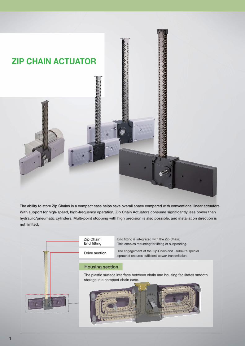
The ability to store Zip Chains in a compact case helps save overall space compared with conventional linear actuators.
With support for high-speed, high-frequency operation, Zip Chain Actuators consume significantly less power than
hydraulic/pneumatic cylinders. Multi-point stopping with high precision is also possible, and installation direction is
not limited.
Housing section
Zip ChainEnd fitting
The plastic surface interface between chain and housing facilitates smooth
storage in a compact chain case.
End fitting is integrated with the Zip Chain.
This enables mounting for lifting or suspending.
The engagement of the Zip Chain and Tsubaki’s special
sprocket ensures sufficient power transmission.Drive section
ACTUATOR
Zip Chains in a compact case helps save overall space compareredd wiwithth ccononvev ntional linear a tctctuauauauatototoorrs.
1
Features
Product lineup
ZIP CHAIN ACTUATOR
TERVO reducer
for servo motors
・ Pneumatic cylinder
・ Hydraulic cylinderStroke: 2,000 mm
Reduced space
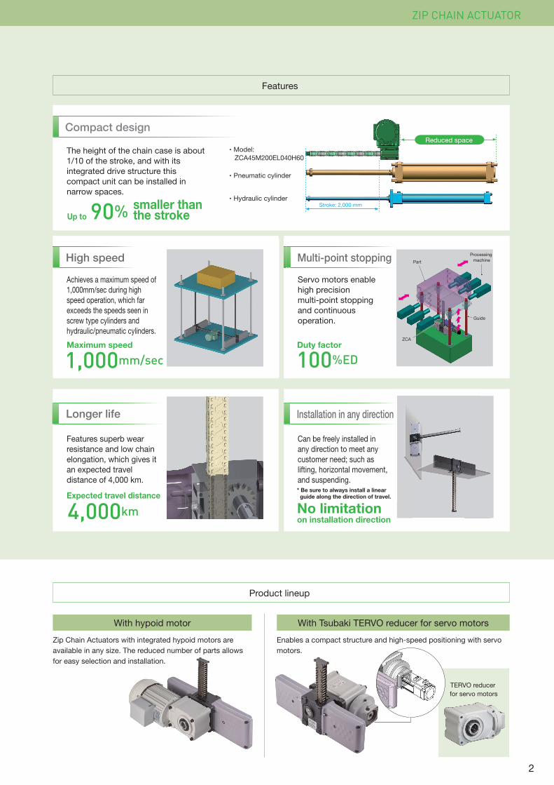
The height of the chain case is about
1/10 of the stroke, and with its
integrated drive structure this
compact unit can be installed in
narrow spaces.
Achieves a maximum speed of
1,000mm/sec during high
speed operation, which far
exceeds the speeds seen in
screw type cylinders and
hydraulic/pneumatic cylinders.
Features superb wear
resistance and low chain
elongation, which gives it
an expected travel
distance of 4,000 km.
Can be freely installed in
any direction to meet any
customer need; such as
lifting, horizontal movement,
and suspending.
Servo motors enable
high precision
multi-point stopping
and continuous
operation.
High speed
Installation in any direction
1,000mm/sec 100%ED
90%
With hypoid motor With Tsubaki TERVO reducer for servo motors
Enables a compact structure and high-speed positioning with servo
motors.
Zip Chain Actuators with integrated hypoid motors are
available in any size. The reduced number of parts allows
for easy selection and installation.
Multi-point stopping
Longer life
Compact design
・ Model:
ZCA45M200EL040H60
Up to
Duty factor
4,000kmExpected travel distance
No limitation
on installation direction
Maximum speed
smaller than the stroke
ZCA
Guide
Processing
machinePart
d of
n
ers.
sec
* Be sure to always install a linear guide along the direction of travel.
2
Pallet transfer
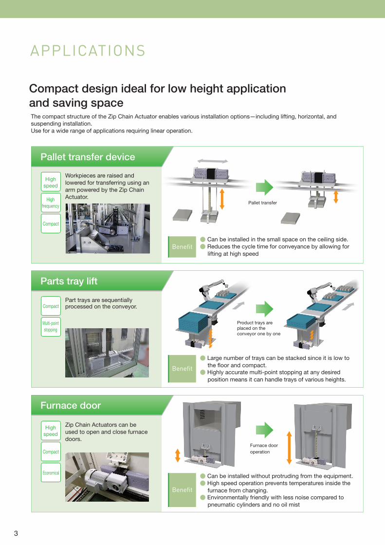
APPLICATIONS
Compact design ideal for low height application
and saving space
Pallet transfer device
Workpieces are raised and
lowered for transferring using an
arm powered by the Zip Chain
Actuator.
Benefit
Parts tray lift
Benefit
Benefit
Furnace door
Furnace door
operation
Product trays are placed on the conveyor one by one
The compact structure of the Zip Chain Actuator enables various installation options—including lifting, horizontal, and
suspending installation.
Use for a wide range of applications requiring linear operation.
Part trays are sequentially processed on the conveyor.
Zip Chain Actuators can be
used to open and close furnace
doors.
High
speed
High
frequency
Compact
Compact
Multi-point
stopping
High
speed
Compact
Economical
● Can be installed in the small space on the ceiling side.
● Reduces the cycle time for conveyance by allowing for
lifting at high speed
● Large number of trays can be stacked since it is low to
the floor and compact.
● Highly accurate multi-point stopping at any desired
position means it can handle trays of various heights.
● Can be installed without protruding from the equipment.
● High speed operation prevents temperatures inside the
furnace from changing.
● Environmentally friendly with less noise compared to
pneumatic cylinders and no oil mist
3
Benefit
Benefit
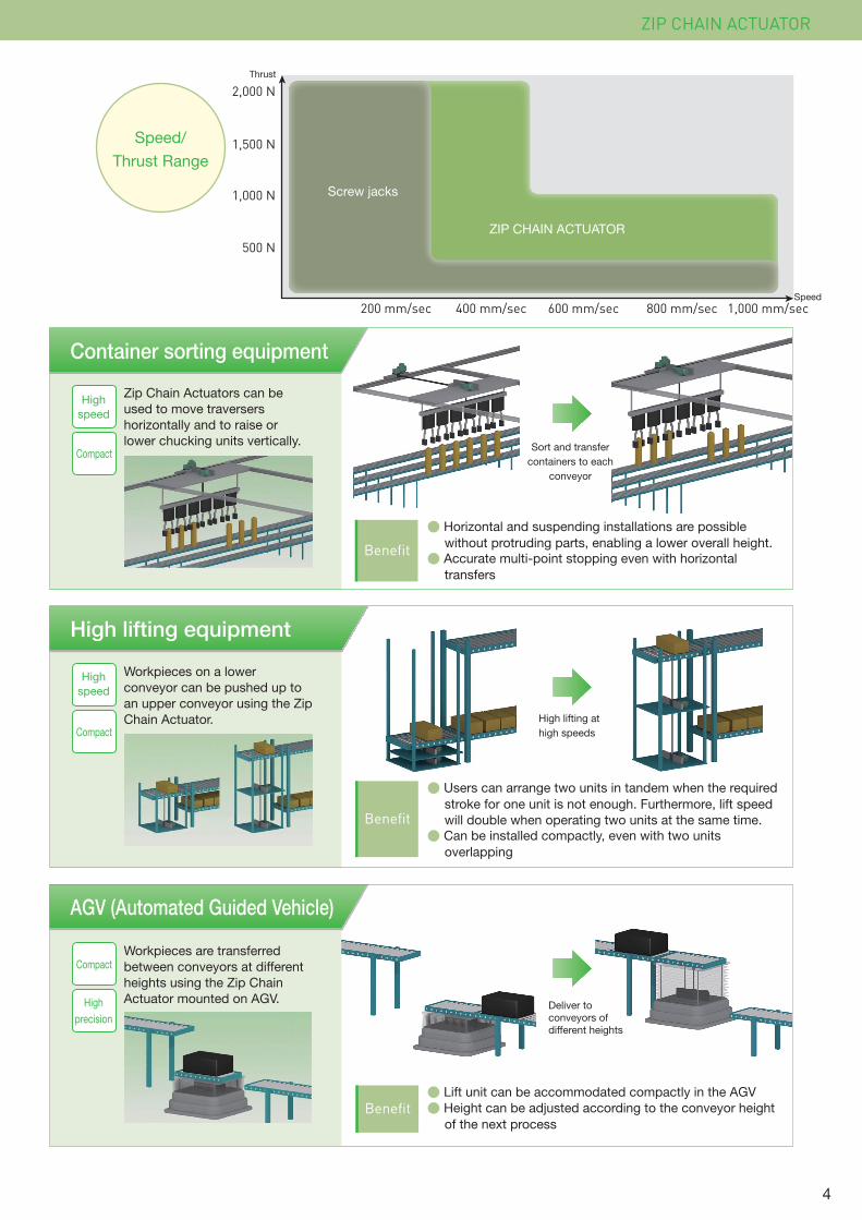
Container sorting equipment
High lifting equipment
High lifting at
high speeds
AGV (Automated Guided Vehicle)
Benefit
Deliver to conveyors of different heights
ZIP CHAIN ACTUATOR
Workpieces on a lower
conveyor can be pushed up to
an upper conveyor using the Zip
Chain Actuator.
Workpieces are transferred
between conveyors at different
heights using the Zip Chain
Actuator mounted on AGV.
High
speed
Compact
High
speed
Compact
Compact
High
precision
2,000 N
1,500 N
1,000 N
500 N
1,000 mm/sec400 mm/sec200 mm/sec 600 mm/sec 800 mm/secSpeed
Thrust
ZIP CHAIN ACTUATOR
Screw jacks
Zip Chain Actuators can be
used to move traversers
horizontally and to raise or
lower chucking units vertically.Sort and transfer
containers to each
conveyor
Speed/
Thrust Range
● Users can arrange two units in tandem when the required
stroke for one unit is not enough. Furthermore, lift speed
will double when operating two units at the same time.
● Can be installed compactly, even with two units
overlapping
● Lift unit can be accommodated compactly in the AGV
● Height can be adjusted according to the conveyor height
of the next process
● Horizontal and suspending installations are possible
without protruding parts, enabling a lower overall height.
● Accurate multi-point stopping even with horizontal
transfers
4
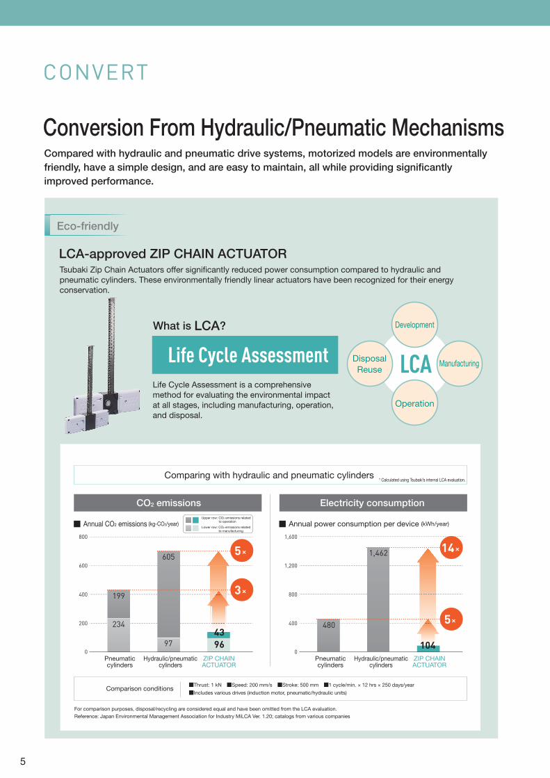
Eco-friendly
LCA-approved ZIP CHAIN ACTUATORTsubaki Zip Chain Actuators offer significantly reduced power consumption compared to hydraulic and
pneumatic cylinders. These environmentally friendly linear actuators have been recognized for their energy
conservation.
Life Cycle Assessment is a comprehensive
method for evaluating the environmental impact
at all stages, including manufacturing, operation,
and disposal.
CONVERT
Conversion From Hydraulic/Pneumatic MechanismsCompared with hydraulic and pneumatic drive systems, motorized models are environmentally
friendly, have a simple design, and are easy to maintain, all while providing significantly
improved performance.
Upper row: CO2 emissions related to operation
Lower row: CO2 emissions related to manufacturing
Comparing with hydraulic and pneumatic cylinders
Hydraulic/pneumaticcylinders
Pneumaticcylinders
Comparison conditions■Thrust: 1 kN ■Speed: 200 mm/s ■Stroke: 500 mm ■1 cycle/min. × 12 hrs × 250 days/year ■Includes various drives (induction motor, pneumatic/hydraulic units)
For comparison purposes, disposal/recycling are considered equal and have been omitted from the LCA evaluation.
Reference: Japan Environmental Management Association for Industry MiLCA Ver. 1.20; catalogs from various companies
ZIP CHAINACTUATOR
Hydraulic/pneumaticcylinders
Pneumaticcylinders
ZIP CHAINACTUATOR
CO2 emissions Electricity consumption
■ Annual CO2 emissions (kg-CO2/year) ■ Annual power consumption per device (kWh/year)
* Calculated using Tsubaki’s internal LCA evaluation.
0
200 234
97
480
1,462
1044396
605
199400
600
800
0
400
800
1,200
1,600
LCA
Development
Operation
Disposal
ReuseManufacturing
434343
3×
5×
10441101044
5×
14×
What is LCA?
Life Cycle Assessment
5
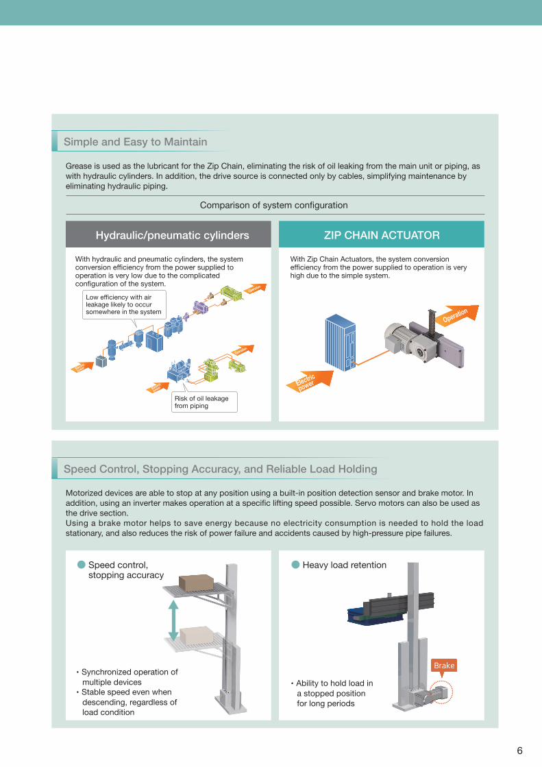
Simple and Easy to Maintain
Grease is used as the lubricant for the Zip Chain, eliminating the risk of oil leaking from the main unit or piping, as
with hydraulic cylinders. In addition, the drive source is connected only by cables, simplifying maintenance by
eliminating hydraulic piping.
Motorized devices are able to stop at any position using a built-in position detection sensor and brake motor. In
addition, using an inverter makes operation at a specific lifting speed possible. Servo motors can also be used as
the drive section.
Using a brake motor helps to save energy because no electricity consumption is needed to hold the load
stationary, and also reduces the risk of power failure and accidents caused by high-pressure pipe failures.
Speed Control, Stopping Accuracy, and Reliable Load Holding
Comparison of system configuration
Hydraulic/pneumatic cylinders ZIP CHAIN ACTUATOR
Operation
Electric
powerElectric
power
With Zip Chain Actuators, the system conversion efficiency from the power supplied to operation is very high due to the simple system.
With hydraulic and pneumatic cylinders, the system conversion efficiency from the power supplied to operation is very low due to the complicated configuration of the system.
● Speed control, stopping accuracy
● Heavy load retention
Low efficiency with air leakage likely to occur somewhere in the system
Risk of oil leakage from piping
・ Synchronized operation of
multiple devices
・ Stable speed even when
descending, regardless of
load condition
・ Ability to hold load in
a stopped position
for long periods
Brake
d retention
d load in
osition
ds
Brakera
Operation
Electric
power
Operation
6

7
Even during high-speed operation, the chains mesh together
smoothly, and ZCA can achieve speeds of 1,000 mm/sec. Even
during high-frequency operation, heat generation is minimized,
no duty factor restrictions are applied, and continuous
operation is possible.
Speed/frequency
Chains stored individually in the chain cases creates an
impressive, space-saving design, where conventional system
requires certain space according to the stroke length.
Compact Footprint
A compressive load is constantly
applied to the lifter, ensuring
highly precise positioning.
Stopping accuracy
Chains coupled together smoothly
for low-noise operation.
Low noise
Zip Chains offer excellent wear
resistance with no elongation of
chains used in power transmission
or transportation, ensuring a long
service life and excellent
maintainability.
Durability
ZIP CHAIN ACTUATOR
Screw jacks Hydraulic/pneumatic mechanisms
Compact storage is possible even
with long strokes, making
transportation and installation
easy.
Ease of use
Tsubaki Zip Chain Products
See page 8
ctTsubaki Zip Chain Produ
ZIP CHAIN ACTUATOR
Comparing Conventional Linear Motion Mechanisms
Compared with screw jacks and hydraulic/pneumatic mechanisms, Zip Chain Actuators offer incredibly superior performance.
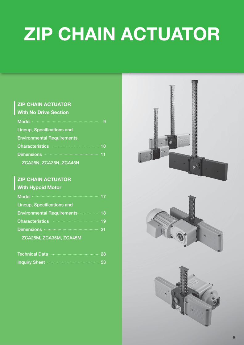
ZIP CHAIN ACTUATOR
ZIP CHAIN ACTUATOR With No Drive Section
Model 9
Lineup, Specifications and
Environmental Requirements,
Characteristics 10
Dimensions 11
ZCA25N, ZCA35N, ZCA45N
ZIP CHAIN ACTUATOR With Hypoid Motor
Model 17
Lineup, Specifications and
Environmental Requirements 18
Characteristics 19
Dimensions 21
ZCA25M, ZCA35M, ZCA45M
Technical Data 28
Inquiry Sheet 53
8
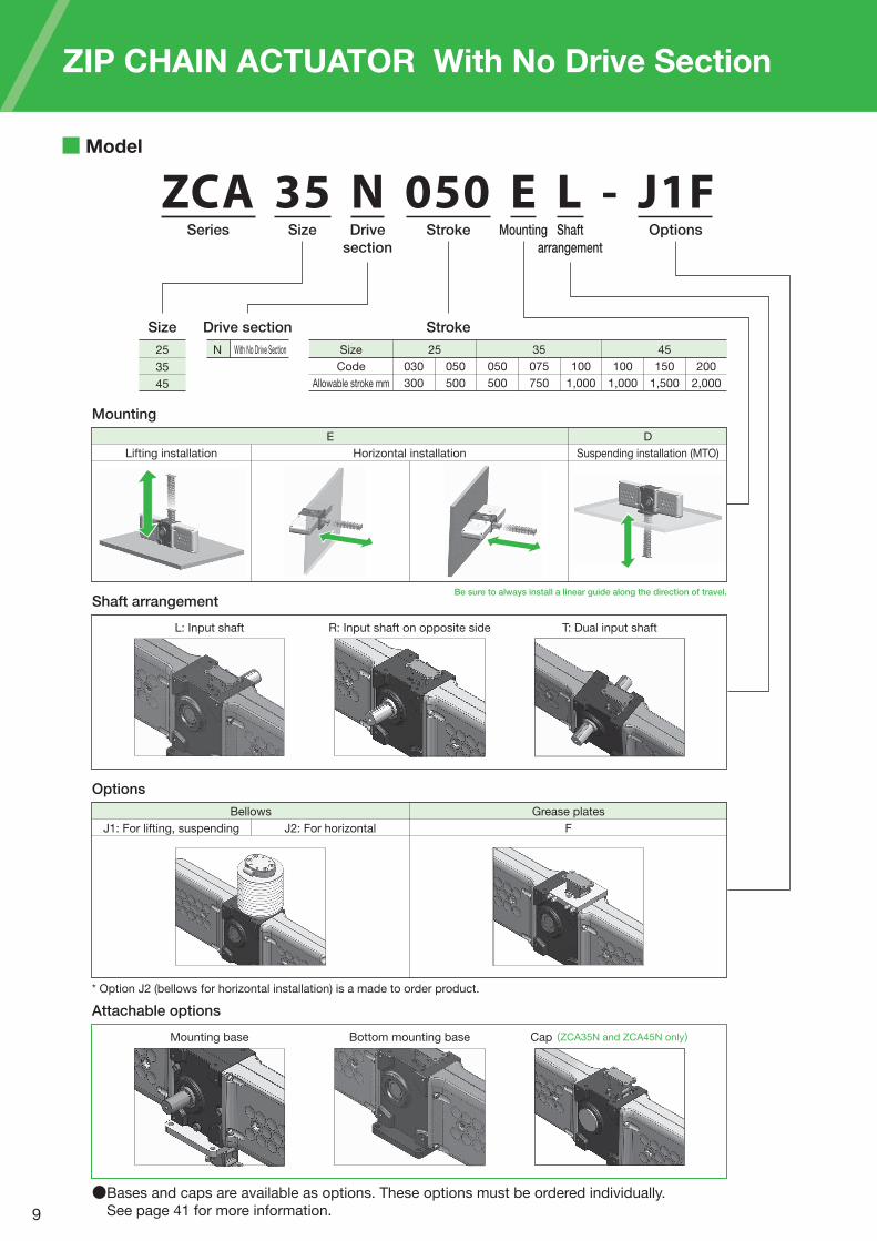
ZCA 35 N 050 E L - J1FSeries Size Drive
section
Stroke Mounting Shaft
arrangement
Options
Model
Lifting installation
E D
Horizontal installation Suspending installation (MTO)
Mounting
Be sure to always install a linear guide along the direction of travel.
Size
25
35
45
Drive section
N With No Drive Section Size
Code
Allowable stroke mm
25
030
300
050
500
050
500
075
750
100
1,000
100
1,000
150
1,500
200
2,000
35 45
Stroke
R: Input shaft on opposite sideL: Input shaft T: Dual input shaft
Bellows Grease plates
Shaft arrangement
Bottom mounting baseMounting base Cap (ZCA35N and ZCA45N only)
J1: For lifting, suspending J2: For horizontal F
Options
Attachable options
●Bases and caps are available as options. These options must be ordered individually.
See page 41 for more information.
ZIP CHAIN ACTUATOR With No Drive Section
* Option J2 (bellows for horizontal installation) is a made to order product.
9
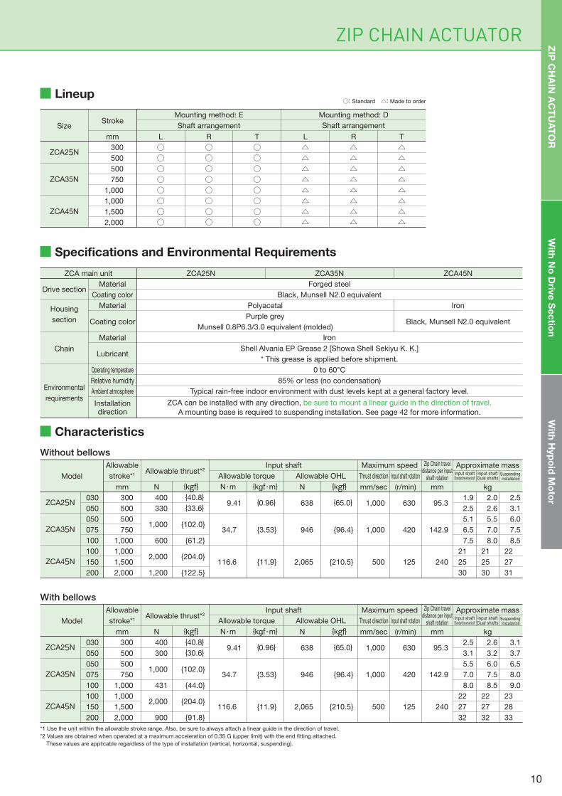
Lineup
Specifications and Environmental Requirements
Drive section
Housing
section
Chain
Environmental
requirements
Material
Coating color
Material
Coating color
Material
Lubricant
Operating temperature
Relative humidity
Ambient atmosphere
Installationdirection
ZCA25NZCA main unit ZCA35N ZCA45N
Forged steel
Black, Munsell N2.0 equivalent
Iron
Shell Alvania EP Grease 2 [Showa Shell Sekiyu K. K.]
* This grease is applied before shipment.
0 to 60°C
85% or less (no condensation)
Typical rain-free indoor environment with dust levels kept at a general factory level.
ZCA can be installed with any direction, be sure to mount a linear guide in the direction of travel.
A mounting base is required to suspending installation. See page 42 for more information.
Polyacetal
Purple grey
Munsell 0.8P6.3/3.0 equivalent (molded)
Iron
Black, Munsell N2.0 equivalent
Without bellows
SizeStroke
mm
Mounting method: E Mounting method: D
Shaft arrangement
L R T L R T
○○○○○○○○
300
500
500
750
1,000
1,000
1,500
2,000
ZCA25N
ZCA35N
ZCA45N
○○○○○○○○
○○○○○○○○
△△△△△△△△
△△△△△△△△
△△△△△△△△
Shaft arrangement
030
050
300
500
400
330
{40.8}{33.6} 9.41 {0.96} 638 {65.0} 1,000 630 95.3
1.9
2.5
2.0
2.6
2.5
3.1ZCA25N
050
075
100
500
750
1,000
1,000
600
{102.0}
{61.2}
34.7 {3.53} 946 {96.4} 1,000 420 142.9
5.1
6.5
7.5
5.5
7.0
8.0
6.0
7.5
8.5
ZCA35N
100
150
200
1,000
1,500
2,000
2,000
1,200
{204.0}
{122.5}
116.6 {11.9} 2,065 {210.5} 500 125 240
21
25
30
21
25
30
22
27
31
ZCA45N
With bellows
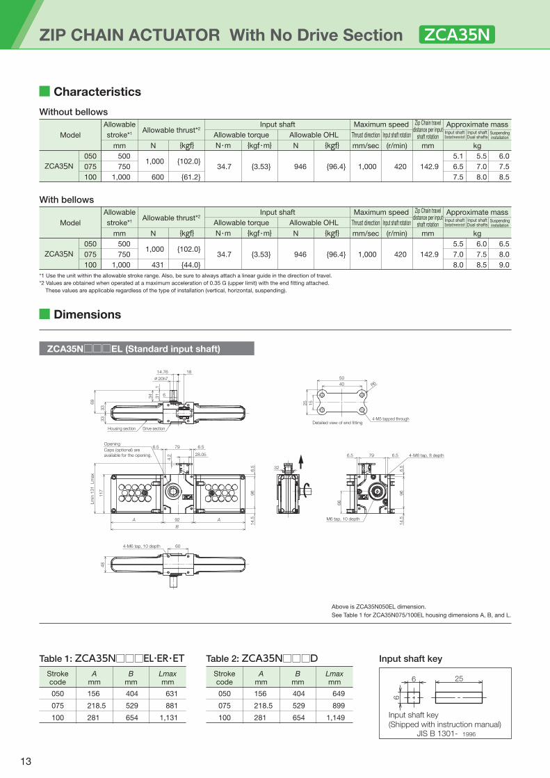
Characteristics
ZIP CHAIN ACTUATOR ZIP
CH
AIN
AC
TU
AT
OR
With
No
Driv
e S
ec
tion
With
Hyp
oid
Mo
tor
○: Standard △: Made to order
Model
Allowable
stroke*1
mm
Input shaft Maximum speed Zip Chain traveldistance per input
shaft rotation
Approximate mass
Allowable torque Allowable OHL Thrust direction Input shaft rotationAllowable thrust*2
N {kgf} N・m {kgf・m} N {kgf} mm/sec (r/min) mm kg
Input shaftStandard/reverse shaft
Input shaftDual shafts
Suspending installation
030
050
300
500
400
300
{40.8}{30.6} 9.41 {0.96} 638 {65.0} 1,000 630 95.3
2.5
3.1
2.6
3.2
3.1
3.7ZCA25N
050
075
100
500
750
1,000
1,000
431
{102.0}
{44.0}
34.7 {3.53} 946 {96.4} 1,000 420 142.9
5.5
7.0
8.0
6.0
7.5
8.5
6.5
8.0
9.0
ZCA35N
100
150
200
1,000
1,500
2,000
2,000
900
{204.0}
{91.8}
116.6 {11.9} 2,065 {210.5} 500 125 240
22
27
32
22
27
32
23
28
33
ZCA45N
*1 Use the unit within the allowable stroke range. Also, be sure to always attach a linear guide in the direction of travel.
*2 Values are obtained when operated at a maximum acceleration of 0.35 G (upper limit) with the end fitting attached.
These values are applicable regardless of the type of installation (vertical, horizontal, suspending).
Model
Allowable
stroke*1
mm
Input shaft Maximum speed Zip Chain traveldistance per input
shaft rotation
Approximate mass
Allowable torque Allowable OHL Thrust direction Input shaft rotationAllowable thrust*2
N {kgf} N・m {kgf・m} N {kgf} mm/sec (r/min) mm kg
Input shaftStandard/reverse shaft
Input shaftDual shafts
Suspending installation
10
030
050
300
500
400
300
{40.8}{30.6} 9.41 {0.96} 638 {65.0} 1,000 630 95.3
2.5
3.1
2.6
3.2
3.1
3.7ZCA25N
030
050
300
500
400
330
{40.8}{33.6} 9.41 {0.96} 638 {65.0} 1,000 630 95.3
1.9
2.5
2.0
2.6
2.5
3.1ZCA25N
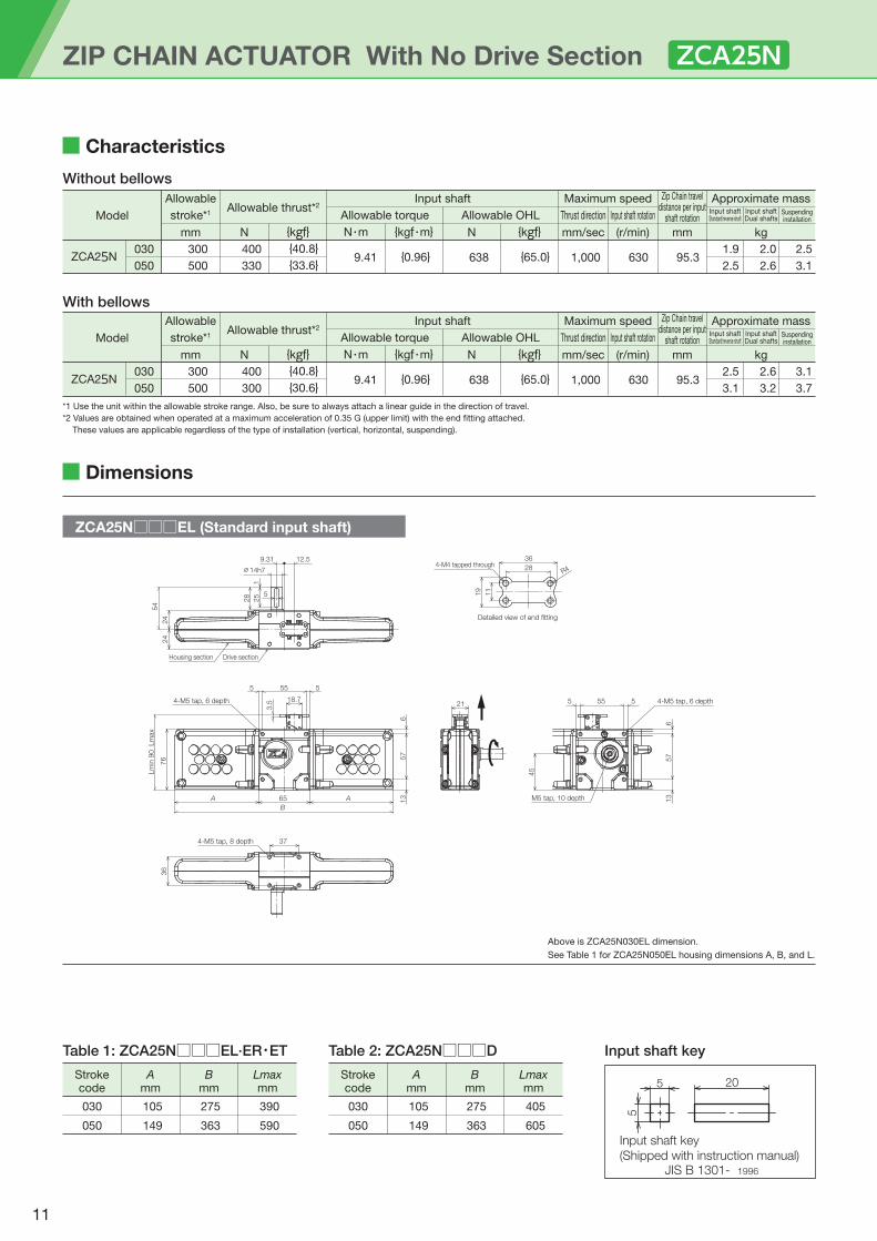
ZCA25N□□□EL (Standard input shaft)
ZIP CHAIN ACTUATOR With No Drive Section
Dimensions
Characteristics
Table 1: ZCA25N□□□EL·ER・ET Input shaft key
Detailed view of end fitting
28
11
19
36
R44-M4 tapped through
Drive sectionHousing section
9.31
24
25
28
54
24
5
12.5
1
∅14h7
37
36
4-M5 tap, 8 depth
4-M5 tap, 6 depth
6
57
13
5 55 5
65A
18.7
Lm
in 9
0 Lm
ax
76
A
3.5
B
21
6
M5 tap, 10 depth
555 5
57
4-M5 tap, 6 depth
13
45
Above is ZCA25N030EL dimension.
See Table 1 for ZCA25N050EL housing dimensions A, B, and L.
030 105 275 390
050 149 363 590
Bmm
Lmaxmm
Amm
Strokecode
030 105 275 405
050 149 363 605
Bmm
Lmaxmm
Amm
Strokecode
Table 2: ZCA25N□□□D
ZCA25N
Without bellows
With bellows
*1 Use the unit within the allowable stroke range. Also, be sure to always attach a linear guide in the direction of travel.
*2 Values are obtained when operated at a maximum acceleration of 0.35 G (upper limit) with the end fitting attached.
These values are applicable regardless of the type of installation (vertical, horizontal, suspending).
Input shaft key
(Shipped with instruction manual)JIS B 1301- 1996
5
5 20
Model
Allowable
stroke*1
mm
Input shaft Maximum speed Zip Chain traveldistance per input
shaft rotation
Approximate mass
Allowable torque Allowable OHL Thrust direction Input shaft rotationAllowable thrust*2
N {kgf} N・m {kgf・m} N {kgf} mm/sec (r/min) mm kg
Input shaftStandard/reverse shaft
Input shaftDual shafts
Suspendinginstallation
11
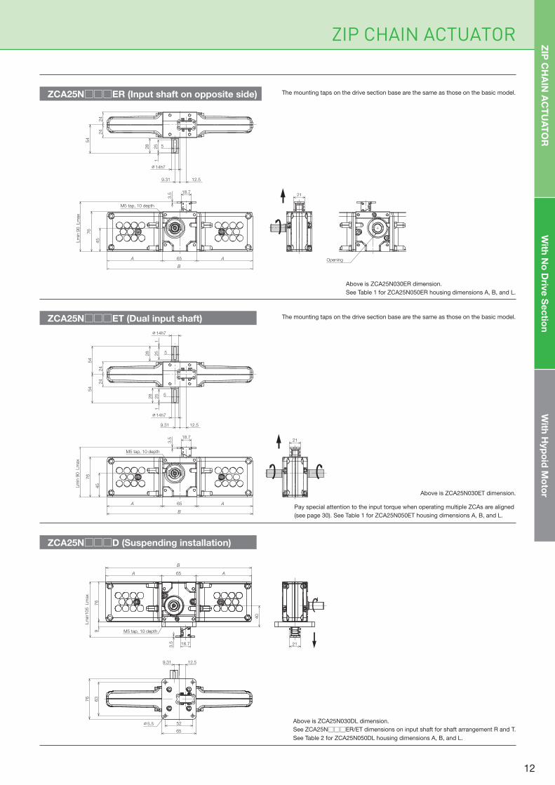
ZIP CHAIN ACTUATOR
Above is ZCA25N030ER dimension.
See Table 1 for ZCA25N050ER housing dimensions A, B, and L.
Above is ZCA25N030DL dimension.
See ZCA25N□□□ER/ET dimensions on input shaft for shaft arrangement R and T.
See Table 2 for ZCA25N050DL housing dimensions A, B, and L.
Pay special attention to the input torque when operating multiple ZCAs are aligned
(see page 30). See Table 1 for ZCA25N050ET housing dimensions A, B, and L.
The mounting taps on the drive section base are the same as those on the basic model.
The mounting taps on the drive section base are the same as those on the basic model.
Above is ZCA25N030ET dimension.
ZCA25N□□□ER (Input shaft on opposite side)
ZCA25N□□□ET (Dual input shaft)
ZCA25N□□□D (Suspending installation)
18.7
3.5
Lm
in 9
0 Lm
ax
76
A 65 A
B
M5 tap, 10 depth
45
125
28
54
24
24
9.31 12.5
5
∅14h7
5
25
28
1
∅14h7
54
18.7
3.5
Lm
in 9
0 Lm
ax
76
A 65 A
B
M5 tap, 10 depth
45
125
28
54
24
24
9.31 12.5
5
∅14h7
Opening
21
21
With
No
Driv
e S
ec
tion
With
Hyp
oid
Mo
tor
ZIP
CH
AIN
AC
TU
AT
OR
21
76
9
40
Lm
in105 Lm
ax
M5 tap, 10 depth
A 65 A
B
18.7
3.5
52
65
∅5.5
63
76
9.31 12.5
12
050
075
100
500
750
1,000
1,000
431
{102.0}
{44.0}
34.7 {3.53} 946 {96.4} 1,000 420 142.9
5.5
7.0
8.0
6.0
7.5
8.5
6.5
8.0
9.0
ZCA35N
050
075
100
500
750
1,000
1,000
600
{102.0}
{61.2}
34.7 {3.53} 946 {96.4} 1,000 420 142.9
5.1
6.5
7.5
5.5
7.0
8.0
6.0
7.5
8.5
ZCA35N
Characteristics
79
14.5
96
6.5
6.56.5
66
4-M6 tap, 8 depth
M6 tap, 10 depth
14.5
96
6.5
79 6.56.5Opening
Caps (optional) are
available for the opening.
117
28.05
92
Lm
in 1
31 Lm
ax
4.2
AA
B
Detailed view of end fitting
15
4-M5 tapped through
25
40
50
R5
32
604-M6 tap, 10 depth
48
Drive sectionHousing section
14.76
33
6
18
31
34
69
1
33
∅20h7
ZCA35N□□□EL (Standard input shaft)
Model
Allowable
stroke*1
mm
Input shaft Maximum speed Zip Chain traveldistance per input
shaft rotation
Approximate mass
Allowable torque Allowable OHL Thrust direction Input shaft rotationAllowable thrust*2
N {kgf} N・m {kgf・m} N {kgf} mm/sec (r/min) mm kg
Input shaftStandard/reverse shaft
Input shaftDual shafts
Suspendinginstallation
*1 Use the unit within the allowable stroke range. Also, be sure to always attach a linear guide in the direction of travel.
*2 Values are obtained when operated at a maximum acceleration of 0.35 G (upper limit) with the end fitting attached.
These values are applicable regardless of the type of installation (vertical, horizontal, suspending).
Without bellows
With bellows
Dimensions
Table 1: ZCA35N□□□EL·ER・ET Input shaft key
050 156 404 631
075 218.5 529 881
100 281 654 1,131
Bmm
Lmaxmm
Amm
Strokecode
050 156 404 649
075 218.5 529 899
100 281 654 1,149
Bmm
Lmaxmm
Amm
Strokecode
Table 2: ZCA35N□□□D
6
6 25
Input shaft key
(Shipped with instruction manual)JIS B 1301- 1996
ZIP CHAIN ACTUATOR With No Drive Section ZCA35N
Model
Allowable
stroke*1
mm
Input shaft Maximum speed Zip Chain traveldistance per input
shaft rotation
Approximate mass
Allowable torque Allowable OHL Thrust direction Input shaft rotationAllowable thrust*2
N {kgf} N・m {kgf・m} N {kgf} mm/sec (r/min) mm kg
Input shaftStandard/reverse shaft
Input shaftDual shafts
Suspendinginstallation
Above is ZCA35N050EL dimension.
See Table 1 for ZCA35N075/100EL housing dimensions A, B, and L.
13
ZIP CHAIN ACTUATOR
32
Caps (optional)
are available for
the opening.
Opening
M6 tap, 10 depth
92
Lm
in 1
31 Lm
ax
28.05
117
4.2
66
AA
B
33
33
69
631
34
14.76
1
18
∅20h7
32
Same for opposite side
92
28.05
A
M6 tap, 10 depth
66
117
Lm
in 1
31 Lm
ax
A
4.2
B
14.76 18
34
33
33
69
69
6
131
31 6
1
34
∅20h7
∅20h7
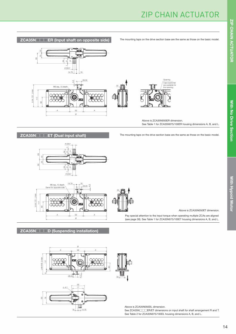
Above is ZCA35N050ER dimension.
See Table 1 for ZCA35N075/100ER housing dimensions A, B, and L.
The mounting taps on the drive section base are the same as those on the basic model.
The mounting taps on the drive section base are the same as those on the basic model.
Above is ZCA35N050ET dimension.
ZCA35N□□□ER (Input shaft on opposite side)
ZCA35N□□□ET (Dual input shaft)
ZCA35N□□□D (Suspending installation)
Above is ZCA35N050DL dimension.
See ZCA35N□□□ER/ET dimensions on input shaft for shaft arrangement R and T.
See Table 2 for ZCA35N075/100DL housing dimensions A, B, and L.
Pay special attention to the input torque when operating multiple ZCAs are aligned
(see page 30). See Table 1 for ZCA35N075/100ET housing dimensions A, B, and L.
With
No
Driv
e S
ec
tion
With
Hyp
oid
Mo
tor
ZIP
CH
AIN
AC
TU
AT
OR
Lm
in149 Lm
ax
9117
60
A 92 A
B
28.05
4.2
77
78
93
92
4-∅7
14.7618
32
14
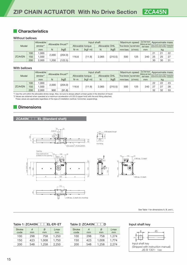
ZCA45N□□□EL (Standard shaft)
See Table 1 for dimensions A, B, and L.
100
150
200
1,000
1,500
2,000
2,000
900
{204.0}
{91.8}
116.6 {11.9} 2,065 {210.5} 500 125 240
22
27
32
22
27
32
23
28
33
ZCA45N
100
150
200
1,000
1,500
2,000
2,000
1,200
{204.0}
{122.5}
116.6 {11.9} 2,065 {210.5} 500 125 240
21
25
30
21
25
30
22
27
31
ZCA45N
42.3
110
10 142 10
M6 tap, 10 depth
4-M8 tap, 12 depth
178
10
10
10 142 10
178
10
10
Opening
Caps (optional) are
available for the opening.47
A A
B
162
Lm
in 2
50/L
max
198
184
7
28
12
110
64
4-M8 tap, 12 depth (for mounting)
2233
8
∅25 h7
100
43
43
55
53
1
52.4
Drive section Housing section
54
54
4-M8 tapped through
∅70
End fitting
Characteristics
Without bellows
With bellows
Model
Allowable
stroke*1
mm
Input shaft Maximum speed Zip Chain traveldistance per input
shaft rotation
Approximate mass
Allowable torque Allowable OHL Thrust direction Input shaft rotationAllowable thrust*2
N {kgf} N・m {kgf・m} N {kgf} mm/sec (r/min) mm kg
Input shaftStandard/reverse shaft
Input shaftDual shafts
Suspendinginstallation
*1 Use the unit within the allowable stroke range. Also, be sure to always attach a linear guide in the direction of travel.
*2 Values are obtained when operated at a maximum acceleration of 0.35 G (upper limit) with the end fitting attached.
These values are applicable regardless of the type of installation (vertical, horizontal, suspending).
Dimensions
Table 1: ZCA45N□□□EL·ER・ET Input shaft key
100 298 758 1,250 150 423 1,008 1,750 200 548 1,258 2,250
Bmm
Lmaxmm
Amm
Strokecode
100 298 758 1,274 150 423 1,008 1,774 200 548 1,258 2,274
Bmm
Lmaxmm
Amm
Strokecode
Table 2: ZCA45N□□□D
7
8 45
Input shaft key
(Shipped with instruction manual)JIS B 1301- 1996
ZIP CHAIN ACTUATOR With No Drive Section ZCA45N
15
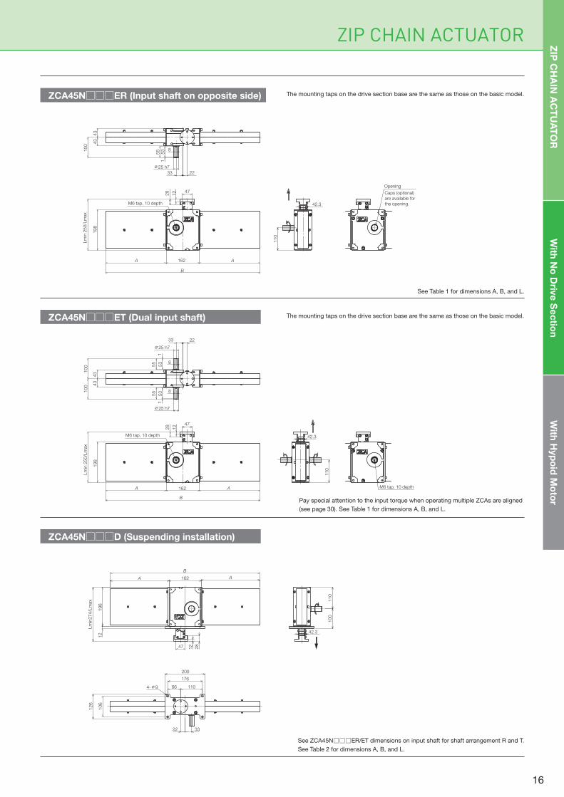
The mounting taps on the drive section base are the same as those on the basic model.
The mounting taps on the drive section base are the same as those on the basic model.ZCA45N□□□ET (Dual input shaft)
ZCA45N□□□D (Suspending installation)
See Table 1 for dimensions A, B, and L.
Pay special attention to the input torque when operating multiple ZCAs are aligned
(see page 30). See Table 1 for dimensions A, B, and L.
ZCA45N□□□ER (Input shaft on opposite side)
See ZCA45N□□□ER/ET dimensions on input shaft for shaft arrangement R and T.
See Table 2 for dimensions A, B, and L.
ZIP CHAIN ACTUATOR
Opening
Caps (optional)
are available for
the opening.42.3
110
2233
8
∅25 h7
100
43
43
55
53
1
A 162 A
B
47
28
198
12
Lm
in 2
50/L
max
M6 tap, 10 depth
A 162 A
B
47
28
198
12
Lm
in 2
50/L
max
M6 tap, 10 depth
M6 tap, 10 depth
42.3
110
2233
8
8
∅25 h7
100
100 4
343
55
53
1
∅25 h7
55
53
1
ZIP
CH
AIN
AC
TU
AT
OR
With
No
Driv
e S
ec
tion
With
Hyp
oid
Mo
tor
198
12
Lm
in274/L
max
47 12
28
A 162 A
B
66 110
200
176
106
126
4-∅9
3322
100
110
42.3
16
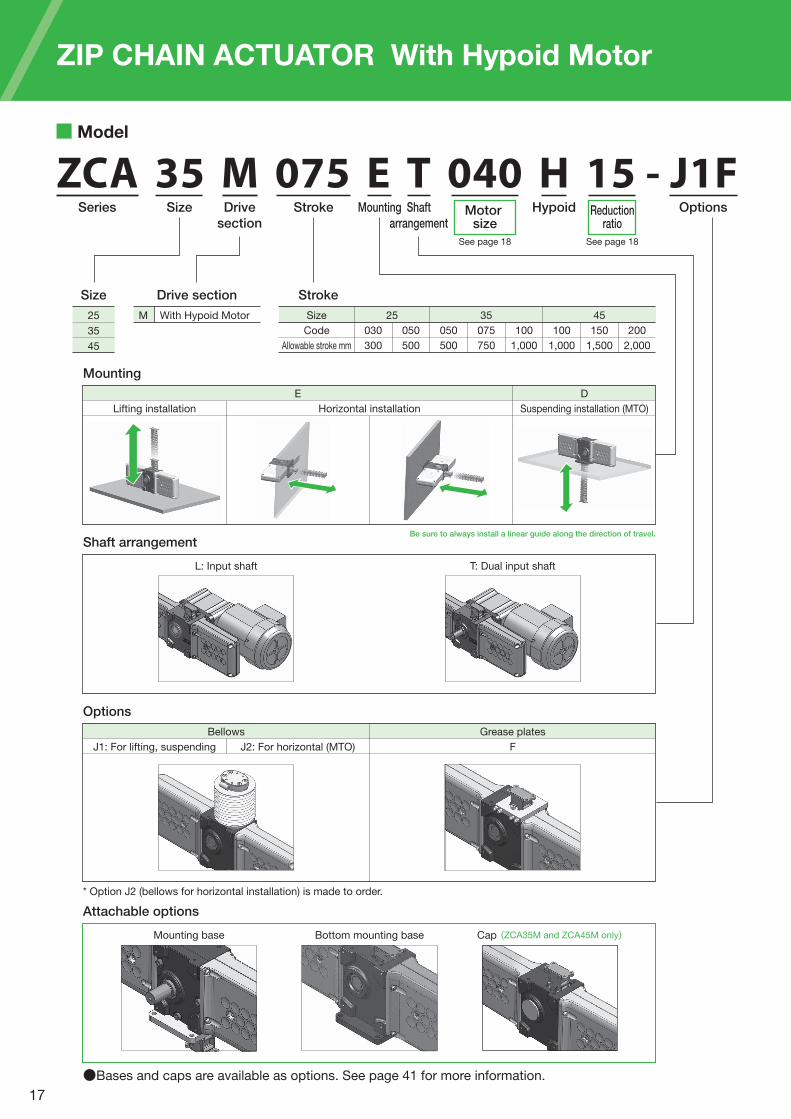
ZCA 35 M 075 E T 040 H 15 - J1FSeries Size Drive
section
Stroke Mounting Shaft
arrangement
OptionsHypoid
Model
Drive section
M With Hypoid Motor
E D
Mounting
Be sure to always install a linear guide along the direction of travel.
Size
25
35
45
Size
Code
Allowable stroke mm
25
030
300
050
500
050
500
075
750
100
1,000
100
1,000
150
1,500
200
2,000
35 45
Stroke
L: Input shaft T: Dual input shaft
Bellows Grease plates
Shaft arrangement
J1: For lifting, suspending J2: For horizontal (MTO) F
Options
Motor size
Reductionratio
See page 18 See page 18
Lifting installation Horizontal installation Suspending installation (MTO)
Bottom mounting baseMounting base Cap (ZCA35M and ZCA45M only)
Attachable options
●Bases and caps are available as options. See page 41 for more information.
* Option J2 (bellows for horizontal installation) is made to order.
ZIP CHAIN ACTUATOR With Hypoid Motor
17
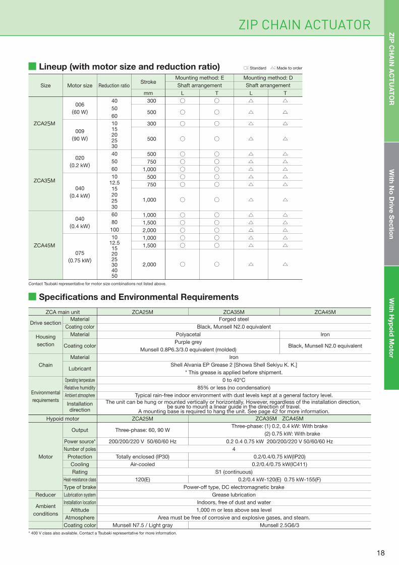
Lineup (with motor size and reduction ratio)
ZIP CHAIN ACTUATOR
Size Motor size Reduction ratioStroke
mm
Mounting method: E Mounting method: D
Shaft arrangement
L T L T
○
○
○
○
○○○○○
○
○○○○○
○
300
500
300
500
500
750
1,000
500
750
1,000
1,000
1,500
2,000
1,000
1,500
2,000
006
(60 W)
009
(90 W)
020
(0.2 kW)
040
(0.4 kW)
040
(0.4 kW)
075
(0.75 kW)
ZCA25M
ZCA35M
ZCA45M
40
50
60
1015202530
40
50
60
1012.515202530
60
80
100
1012.5152025304050
○
○
○
○
○○○○○
○
○○○○○
○
△
△
△
△
△△△△△
△
△△△△△
△
△
△
△
△
△△△△△
△
△△△△△
△
Shaft arrangement
○: Standard △: Made to order
Specifications and Environmental Requirements
ZCA25MZCA main unit ZCA35M ZCA45M
Motor
Reducer
Ambient
conditions
Output
Power source*
Number of poles
Protection
Cooling
Rating
Heat-resistance class
Type of brake
Lubrication system
Installation location
Altitude
Atmosphere
Coating color
ZCA25MHypoid motor ZCA35M ZCA45M
Three-phase: (1) 0.2, 0.4 kW: With brake
(2) 0.75 kW: With brake
0.2 0.4 0.75 kW 200/200/220 V 50/60/60 Hz
Three-phase: 60, 90 W
200/200/220 V 50/60/60 Hz
0.2/0.4/0.75 kW(IP20)
0.2/0.4/0.75 kW(IC411)
Totally enclosed (IP30)
Air-cooled
0.2/0.4 kW-120(E) 0.75 kW-155(F)120(E)
Munsell 2.5G6/3Munsell N7.5 / Light gray
4
S1 (continuous)
Power-off type, DC electromagnetic brake
Grease lubrication
Indoors, free of dust and water
1,000 m or less above sea level
Area must be free of corrosive and explosive gases, and steam.
Contact Tsubaki representative for motor size combinations not listed above.
* 400 V class also available. Contact a Tsubaki representative for more information.
ZIP
CH
AIN
AC
TU
AT
OR
With
No
Driv
e S
ec
tion
With
Hyp
oid
Mo
tor
Drive section
Housing
section
Chain
Environmental
requirements
Material
Coating color
Material
Coating color
Material
Lubricant
Operating temperature
Relative humidity
Ambient atmosphere
Installationdirection
Forged steel
Black, Munsell N2.0 equivalent
Iron
Shell Alvania EP Grease 2 [Showa Shell Sekiyu K. K.]
* This grease is applied before shipment.
0 to 40°C
85% or less (no condensation)
Typical rain-free indoor environment with dust levels kept at a general factory level.
The unit can be hung or mounted vertically or horizontally. However, regardless of the installation direction, be sure to mount a linear guide in the direction of travel.
A mounting base is required to hang the unit. See page 42 for more information.
Polyacetal
Purple grey
Munsell 0.8P6.3/3.0 equivalent (molded)
Iron
Black, Munsell N2.0 equivalent
18

500
750
1,000
020
(0.2 kW)
040
(0.4 kW)
020
(0.2 kW)
040
(0.4 kW)
020
(0.2 kW)
040
(0.4 kW)
40
50
60
10
12.5
15
20
25
30
40
50
60
10
12.5
15
20
25
30
40
50
60
10
12.5
15
20
25
30
*1,000
*1,000
*1,000
617
794
941
*1,000
*1,000
*1,000
*1,000
*1,000
*1,000
617
794
941
*1,000
*1,000
*1,000
*600
*600
*600
*600
*600
*600
*600
*600
*600
*102.0
*102.0
*102.0
63.0
81.0
96.0
*102.0
*102.0
*102.0
*102.0
*102.0
*102.0
63.0
81.0
96.0
*102.0
*102.0
*102.0
*61.2
*61.2
*61.2
*61.2
*61.2
*61.2
*61.2
*61.2
*61.2
91
73
61
365
292
243
183
146
122
91
73
61
365
292
243
183
146
122
91
73
61
365
292
243
183
146
122
110
88
73
438
351
292
219
175
146
110
88
73
438
351
292
219
175
146
110
88
73
438
351
292
219
175
146
10
8
7
3
8
10
10
10
10
10
8
7
3
8
10
10
10
10
10
8
7
3
8
10
10
10
10
10
10
8
5
10
10
10
10
10
10
10
8
5
10
10
10
10
10
10
10
8
5
10
10
10
10
10
14
14
14
18
18
18
18
18
18
15
15
15
19
19
19
19
19
19
16
16
16
20
20
20
20
20
20
14
14
14
18
18
18
18
18
18
15.5
15.5
15.5
19.5
19.5
19.5
19.5
19.5
19.5
16
16
16
20
20
20
20
20
20
15.5
15.5
15.5
19.5
19.5
19.5
19.5
19.5
19.5
16.5
16.5
16.5
21
21
21
21
21
21
17.5
17.5
17.5
21.5
21.5
21.5
21.5
21.5
21.5
ZCA35 M
ZIP CHAIN ACTUATOR With Hypoid Motor
300
500
006
(60 W)
009
(90 W)
006
(60 W)
009
(90 W)
40
50
60
10
15
20
25
30
40
50
60
10
15
20
25
30
*400
*400
*400
166
274
382
*400
*400
*330
*330
*330
166
274
*330
*330
*330
*40.8
*40.8
*40.8
17.0
28.0
39.0
*40.8
*40.8
*33.6
*33.6
*33.6
17.0
28.0
*33.6
*33.6
*33.6
60
48
40
243
162
122
97
82
60
48
40
243
162
122
97
82
73
58
48
292
195
145
117
97
73
58
48
292
195
145
117
97
10
9
8
10
10
10
10
10
10
9
8
10
10
10
10
10
10
10
9
10
10
10
10
10
10
10
9
10
10
10
10
10
10
10
10
10.5
10.5
10.5
10.5
10.5
10.5
10.5
10.5
11
11
11
11
11
10
10
10
10.5
10.5
10.5
10.5
10.5
10.5
10.5
10.5
11
11
11
11
11
11
11
11
11.5
11.5
11.5
11.5
11.5
11.5
11.5
11.5
12
12
12
12
12
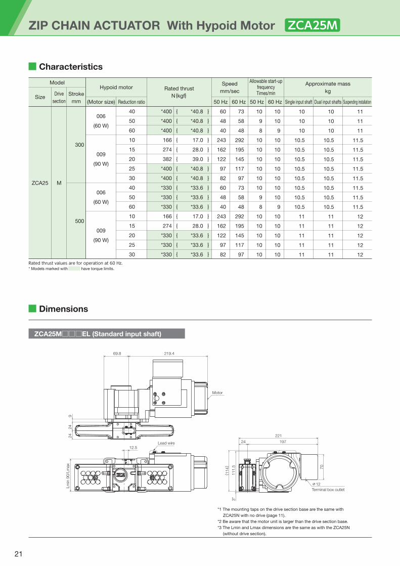
ZCA25 M
Characteristics
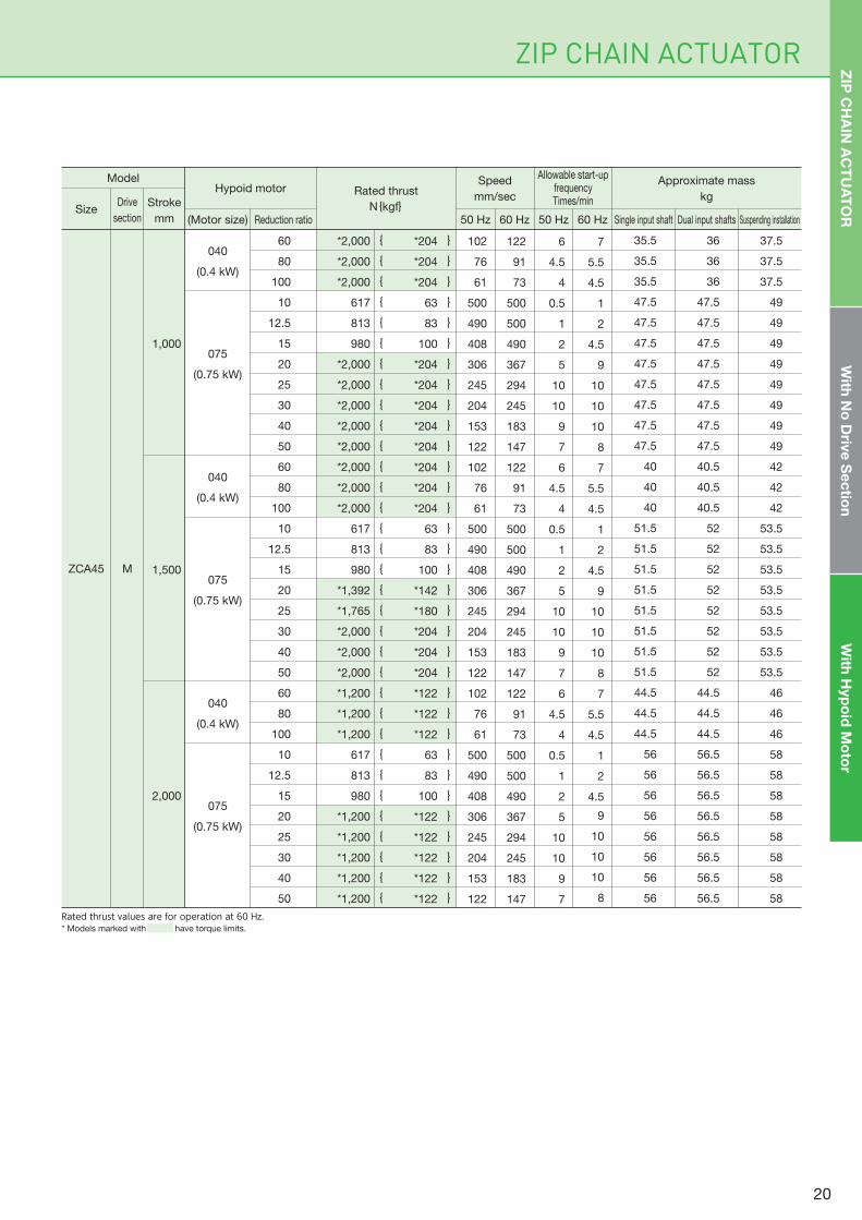
Model
SizeDrive
section
Stroke
mm (Motor size)
Rated thrust
N{kgf}
Approximate mass
kg
Speed
mm/secHypoid motor
Reduction ratio 50 Hz 60 Hz
Allowable start-upfrequencyTimes/min
50 Hz 60 Hz Single input shaft Dual input shafts Suspending installation
{{{{{{{{{{{{{{{{{{{{{{{{{{{
}}}}}}}}}}}}}}}}}}}}}}}}}}}
{{{{{{{{{{{{{{{{
}}}}}}}}}}}}}}}}
Rated thrust values are for operation at 60 Hz.* Models marked with have torque limits.
19
35.5
35.5
35.5
47.5
47.5
47.5
47.5
47.5
47.5
47.5
47.5
40
40
40
51.5
51.5
51.5
51.5
51.5
51.5
51.5
51.5
44.5
44.5
44.5
56
56
56
56
56
56
56
56
36
36
36
47.5
47.5
47.5
47.5
47.5
47.5
47.5
47.5
40.5
40.5
40.5
52
52
52
52
52
52
52
52
44.5
44.5
44.5
56.5
56.5
56.5
56.5
56.5
56.5
56.5
56.5
37.5
37.5
37.5
49
49
49
49
49
49
49
49
42
42
42
53.5
53.5
53.5
53.5
53.5
53.5
53.5
53.5
46
46
46
58
58
58
58
58
58
58
58
040
(0.4 kW)
075
(0.75 kW)
040
(0.4 kW)
075
(0.75 kW)
040
(0.4 kW)
075
(0.75 kW)
60
80
100
10
12.5
15
20
25
30
40
50
60
80
100
10
12.5
15
20
25
30
40
50
60
80
100
10
12.5
15
20
25
30
40
50
1,000
1,500
2,000
*2,000
*2,000
*2,000
617
813
980
*2,000
*2,000
*2,000
*2,000
*2,000
*2,000
*2,000
*2,000
617
813
980
*1,392
*1,765
*2,000
*2,000
*2,000
*1,200
*1,200
*1,200
617
813
980
*1,200
*1,200
*1,200
*1,200
*1,200
*204
*204
*204
63
83
100
*204
*204
*204
*204
*204
*204
*204
*204
63
83
100
*142
*180
*204
*204
*204
*122
*122
*122
63
83
100
*122
*122
*122
*122
*122
102
76
61
500
490
408
306
245
204
153
122
102
76
61
500
490
408
306
245
204
153
122
102
76
61
500
490
408
306
245
204
153
122
122
91
73
500
500
490
367
294
245
183
147
122
91
73
500
500
490
367
294
245
183
147
122
91
73
500
500
490
367
294
245
183
147
6
4.5
4
0.5
1
2
5
10
10
9
7
6
4.5
4
0.5
1
2
5
10
10
9
7
6
4.5
4
0.5
1
2
5
10
10
9
7
7
5.5
4.5
1
2
4.5
9
10
10
10
8
7
5.5
4.5
1
2
4.5
9
10
10
10
8
7
5.5
4.5
1
2
4.5
9
10
10
10
8
ZCA45 M
ZIP CHAIN ACTUATOR
Model
SizeDrive
section
Stroke
mm (Motor size)
Rated thrust
N{kgf}
Approximate mass
kg
Speed
mm/secHypoid motor
Reduction ratio 50 Hz 60 Hz
Allowable start-upfrequencyTimes/min
50 Hz 60 Hz Single input shaft Dual input shafts Suspending installation
{{{{{{{{{{{{{{{{{{{{{{{{{{{{{{{{{
}}}}}}}}}}}}}}}}}}}}}}}}}}}}}}}}}
Rated thrust values are for operation at 60 Hz.* Models marked with have torque limits.
ZIP
CH
AIN
AC
TU
AT
OR
With
No
Driv
e S
ec
tion
With
Hyp
oid
Mo
tor
20
Characteristics
ZIP CHAIN ACTUATOR With Hypoid Motor ZCA25M
ZCA25M□□□EL (Standard input shaft)
Dimensions
*1 The mounting taps on the drive section base are the same with
ZCA25N with no drive (page 11).
*2 Be aware that the motor unit is larger than the drive section base.
*3 The Lmin and Lmax dimensions are the same as with the ZCA25N
(without drive section).
(114)
Motor
24
24
69.8
9
219.4
Lead wire
Lm
in 9
0/L
max
12.5
∅12
Terminal box outlet
197
221
111.5
24
3*
70
300
500
006
(60 W)
009
(90 W)
006
(60 W)
009
(90 W)
40
50
60
10
15
20
25
30
40
50
60
10
15
20
25
30
*400
*400
*400
166
274
382
*400
*400
*330
*330
*330
166
274
*330
*330
*330
*40.8
*40.8
*40.8
17.0
28.0
39.0
*40.8
*40.8
*33.6
*33.6
*33.6
17.0
28.0
*33.6
*33.6
*33.6
60
48
40
243
162
122
97
82
60
48
40
243
162
122
97
82
73
58
48
292
195
145
117
97
73
58
48
292
195
145
117
97
10
9
8
10
10
10
10
10
10
9
8
10
10
10
10
10
10
10
9
10
10
10
10
10
10
10
9
10
10
10
10
10
10
10
10
10.5
10.5
10.5
10.5
10.5
10.5
10.5
10.5
11
11
11
11
11
10
10
10
10.5
10.5
10.5
10.5
10.5
10.5
10.5
10.5
11
11
11
11
11
11
11
11
11.5
11.5
11.5
11.5
11.5
11.5
11.5
11.5
12
12
12
12
12
ZCA25 M
{{{{{{{{{{{{{{{{
}}}}}}}}}}}}}}}}
Rated thrust values are for operation at 60 Hz.* Models marked with have torque limits.
Model
SizeDrive
section
Stroke
mm (Motor size)
Rated thrust
N{kgf}
Approximate mass
kg
Speed
mm/secHypoid motor
Reduction ratio 50 Hz 60 Hz
Allowable start-upfrequencyTimes/min
50 Hz 60 Hz Single input shaft Dual input shafts Suspending installation
21
ZIP CHAIN ACTUATOR
ZCA25M□□□D (Suspending installation)
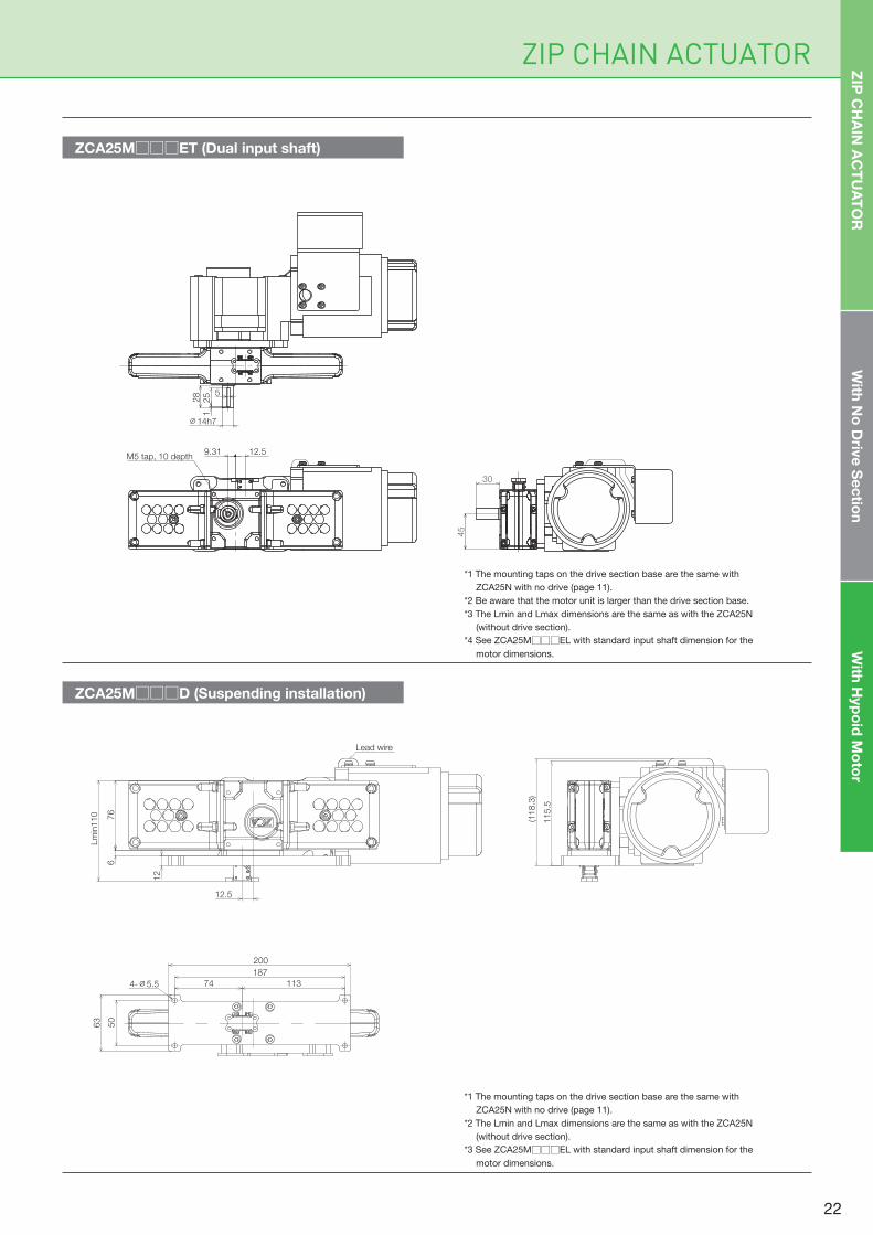
ZCA25M□□□ET (Dual input shaft)
*1 The mounting taps on the drive section base are the same with
ZCA25N with no drive (page 11).
*2 The Lmin and Lmax dimensions are the same as with the ZCA25N
(without drive section).
*3 See ZCA25M□□□EL with standard input shaft dimension for the
motor dimensions.
*1 The mounting taps on the drive section base are the same with
ZCA25N with no drive (page 11).
*2 Be aware that the motor unit is larger than the drive section base.
*3 The Lmin and Lmax dimensions are the same as with the ZCA25N
(without drive section).
*4 See ZCA25M□□□EL with standard input shaft dimension for the
motor dimensions.
5
25
1
∅14h7
28
M5 tap, 10 depth12.59.31
30
45
ZIP
CH
AIN
AC
TU
AT
OR
With
No
Driv
e S
ec
tion
With
Hyp
oid
Mo
tor
Lm
in110
676
12.5
12
Lead wire
74 113
187
200
4-∅5.5
50
63
(118.3
)
115.5
22
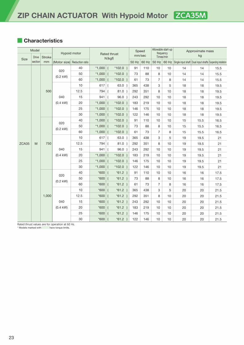
Characteristics
500
750
1,000
020
(0.2 kW)
040
(0.4 kW)
020
(0.2 kW)
040
(0.4 kW)
020
(0.2 kW)
040
(0.4 kW)
40
50
60
10
12.5
15
20
25
30
40
50
60
10
12.5
15
20
25
30
40
50
60
10
12.5
15
20
25
30
*1,000
*1,000
*1,000
617
794
941
*1,000
*1,000
*1,000
*1,000
*1,000
*1,000
617
794
941
*1,000
*1,000
*1,000
*600
*600
*600
*600
*600
*600
*600
*600
*600
*102.0
*102.0
*102.0
63.0
81.0
96.0
*102.0
*102.0
*102.0
*102.0
*102.0
*102.0
63.0
81.0
96.0
*102.0
*102.0
*102.0
*61.2
*61.2
*61.2
*61.2
*61.2
*61.2
*61.2
*61.2
*61.2
91
73
61
365
292
243
183
146
122
91
73
61
365
292
243
183
146
122
91
73
61
365
292
243
183
146
122
110
88
73
438
351
292
219
175
146
110
88
73
438
351
292
219
175
146
110
88
73
438
351
292
219
175
146
10
8
7
3
8
10
10
10
10
10
8
7
3
8
10
10
10
10
10
8
7
3
8
10
10
10
10
10
10
8
5
10
10
10
10
10
10
10
8
5
10
10
10
10
10
10
10
8
5
10
10
10
10
10
14
14
14
18
18
18
18
18
18
15
15
15
19
19
19
19
19
19
16
16
16
20
20
20
20
20
20
14
14
14
18
18
18
18
18
18
15.5
15.5
15.5
19.5
19.5
19.5
19.5
19.5
19.5
16
16
16
20
20
20
20
20
20
15.5
15.5
15.5
19.5
19.5
19.5
19.5
19.5
19.5
16.5
16.5
16.5
21
21
21
21
21
21
17.5
17.5
17.5
21.5
21.5
21.5
21.5
21.5
21.5
ZCA35 M
{{{{{{{{{{{{{{{{{{{{{{{{{{{
}}}}}}}}}}}}}}}}}}}}}}}}}}}
Rated thrust values are for operation at 60 Hz.* Models marked with have torque limits.
ZIP CHAIN ACTUATOR With Hypoid Motor ZCA35M
Model
SizeDrive
section
Stroke
mm (Motor size)
Rated thrust
N{kgf}
Approximate mass
kg
Speed
mm/secHypoid motor
Reduction ratio 50 Hz 60 Hz
Allowable start-upfrequencyTimes/min
50 Hz 60 Hz Single input shaft Dual input shafts Suspending installation
23
ZIP CHAIN ACTUATOR
ZCA35M□□□D (Suspending installation)
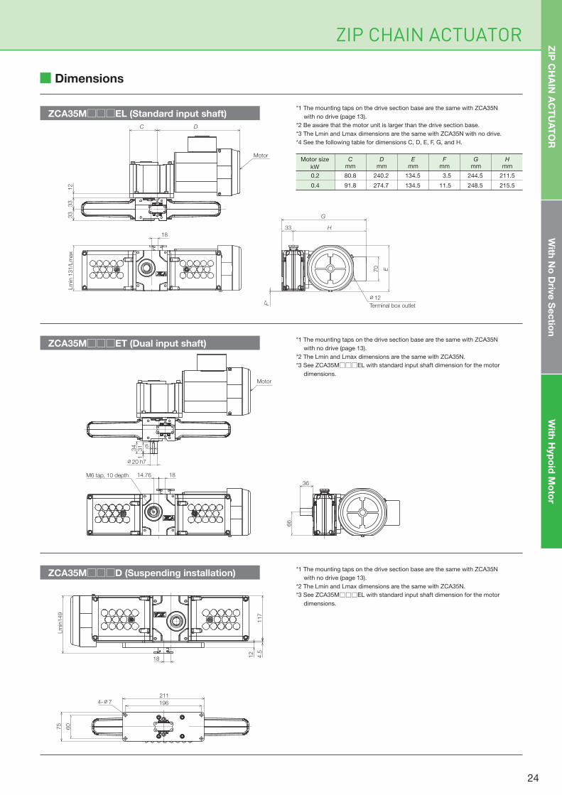
ZCA35M□□□EL (Standard input shaft)
Motor
33
33
12
DC
Lm
in 1
31/L
max
18
Terminal box outlet
33 H
G
70
F*
E
∅12
ZCA35M□□□ET (Dual input shaft)
*1 The mounting taps on the drive section base are the same with ZCA35N
with no drive (page 13).
*2 The Lmin and Lmax dimensions are the same with ZCA35N.
*3 See ZCA35M□□□EL with standard input shaft dimension for the motor
dimensions.
*1 The mounting taps on the drive section base are the same with ZCA35N
with no drive (page 13).
*2 The Lmin and Lmax dimensions are the same with ZCA35N.
*3 See ZCA35M□□□EL with standard input shaft dimension for the motor
dimensions.
*1 The mounting taps on the drive section base are the same with ZCA35N
with no drive (page 13).
*2 Be aware that the motor unit is larger than the drive section base.
*3 The Lmin and Lmax dimensions are the same with ZCA35N with no drive.
*4 See the following table for dimensions C, D, E, F, G, and H.
1814.76M6 tap, 10 depth
34 6
31
1
∅20 h7
Motor
36
66
0.2 80.8 240.2 134.5 3.5 244.5 211.5
0.4 91.8 274.7 134.5 11.5 248.5 215.5
Motor size
kW
Dmm
Emm
Fmm
Gmm
Hmm
Cmm
Dimensions
ZIP
CH
AIN
AC
TU
AT
OR
With
No
Driv
e S
ec
tion
With
Hyp
oid
Mo
tor
117
Lm
in149
18 4.5
12
75
60
211
1964-∅7
24

Characteristics
35.5
35.5
35.5
47.5
47.5
47.5
47.5
47.5
47.5
47.5
47.5
40
40
40
51.5
51.5
51.5
51.5
51.5
51.5
51.5
51.5
44.5
44.5
44.5
56
56
56
56
56
56
56
56
36
36
36
47.5
47.5
47.5
47.5
47.5
47.5
47.5
47.5
40.5
40.5
40.5
52
52
52
52
52
52
52
52
44.5
44.5
44.5
56.5
56.5
56.5
56.5
56.5
56.5
56.5
56.5
37.5
37.5
37.5
49
49
49
49
49
49
49
49
42
42
42
53.5
53.5
53.5
53.5
53.5
53.5
53.5
53.5
46
46
46
58
58
58
58
58
58
58
58
040
(0.4 kW)
075
(0.75 kW)
040
(0.4 kW)
075
(0.75 kW)
040
(0.4 kW)
075
(0.75 kW)
60
80
100
10
12.5
15
20
25
30
40
50
60
80
100
10
12.5
15
20
25
30
40
50
60
80
100
10
12.5
15
20
25
30
40
50
1,000
1,500
2,000
*2,000
*2,000
*2,000
617
813
980
*2,000
*2,000
*2,000
*2,000
*2,000
*2,000
*2,000
*2,000
617
813
980
*1,392
*1,765
*2,000
*2,000
*2,000
*1,200
*1,200
*1,200
617
813
980
*1,200
*1,200
*1,200
*1,200
*1,200
*204
*204
*204
63
83
100
*204
*204
*204
*204
*204
*204
*204
*204
63
83
100
*142
*180
*204
*204
*204
*122
*122
*122
63
83
100
*122
*122
*122
*122
*122
102
76
61
500
490
408
306
245
204
153
122
102
76
61
500
490
408
306
245
204
153
122
102
76
61
500
490
408
306
245
204
153
122
122
91
73
500
500
490
367
294
245
183
147
122
91
73
500
500
490
367
294
245
183
147
122
91
73
500
500
490
367
294
245
183
147
6
4.5
4
0.5
1
2
5
10
10
9
7
6
4.5
4
0.5
1
2
5
10
10
9
7
6
4.5
4
0.5
1
2
5
10
10
9
7
7
5.5
4.5
1
2
4.5
9
10
10
10
8
7
5.5
4.5
1
2
4.5
9
10
10
10
8
7
5.5
4.5
1
2
4.5
9
10
10
10
8
ZCA45 M
{{{{{{{{{{{{{{{{{{{{{{{{{{{{{{{{{
}}}}}}}}}}}}}}}}}}}}}}}}}}}}}}}}}
Rated thrust values are for operation at 60 Hz.* Models marked with have torque limits.
ZIP CHAIN ACTUATOR With Hypoid Motor ZCA45M
Model
SizeDrive
section
Stroke
mm (Motor size)
Rated thrust
N{kgf}
Approximate mass
kg
Speed
mm/secHypoid motor
Reduction ratio 50 Hz 60 Hz
Allowable start-upfrequencyTimes/min
50 Hz 60 Hz Single input shaft Dual input shafts Suspending installation
25
ZIP CHAIN ACTUATOR
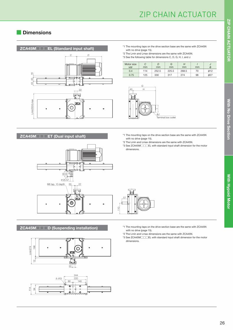
ZCA45M□□□D (Suspending installation)
0.4 114 252.5 225.5 268.5 70 φ12
0.75 125 330 317 274 98 φ27
Motor size
kW
Dmm
Gmm
Hmm
Imm
Jφ
Cmm
ZCA45M□□□ET (Dual input shaft)
ZCA45M□□□EL (Standard input shaft)*1 The mounting taps on the drive section base are the same with ZCA45N
with no drive (page 15).
*2 The Lmin and Lmax dimensions are the same with ZCA45N.
*3 See the following table for dimensions C, D, G, H, I, and J.
*1 The mounting taps on the drive section base are the same with ZCA45N
with no drive (page 15).
*2 The Lmin and Lmax dimensions are the same with ZCA45N.
*3 See ZCA45M□□□EL with standard input shaft dimension for the motor
dimensions.
*1 The mounting taps on the drive section base are the same with ZCA45N
with no drive (page 15).
*2 The Lmin and Lmax dimensions are the same with ZCA45N.
*3 See ZCA45M□□□EL with standard input shaft dimension for the motor
dimensions.
22
Lm
in250/L
max
C D
43
43
16
G
43 H
I
φJTerminal box outlet
2233M6 tap, 10 depth
8
53
155
∅25 h7
57
110
Dimensions
ZIP
CH
AIN
AC
TU
AT
OR
With
No
Driv
e S
ec
tion
With
Hyp
oid
Mo
tor
Lm
in274
198
12
22
80 140
220
244
94
114
4-∅9
26

M E M O
27
ZIP CHAIN ACTUATOR
Technical Data
Product Selection 29
Hypoid Motor 33
Options 39
Grease Plate, Bellows, Cap,
Mounting Base, Global Series
Q & A 47
Handling 49
28

(1) Machine used with the unit ··············Machine structure, number of ZCAs to be used, operating environment, etc.
(2) Load····················································Load characteristics, load/workpiece mass, drive source, drive system, etc.
(3) Installation type ·································Mounting direction (lifting, horizontal, suspending), linear guide system
(4) Operating speed ·······························Speed required for ZCA operation(5) Stroke ·················································Actual stroke to be used
ZIP CHAIN ACTUATOR Technical Data and Product Selection
Selection Chart
Selection Procedure
Product Selection
The chart to the right
presents the relationship
between stroke and
basic capacity.
Select a suitable model
by confirming the
required thrust per ZCA
and stroke in the chart.
If more detailed exam-
ination is necessary,
check if the selection
suits the application
using the calculations
shown below.
ZCA45N150
00
500
1,000
1,200
1,500
2,000
500 1,000 1,500 2,000
Stroke mm
Basic
cap
acity N
ZCA45N100
ZCA45N200
ZCA35N050 ZCA35N075
ZCA35N100
ZCA25N030
ZCA25N050
Table 1 — Service factor Sf
Table 2 — Load-sharing factor
Consider the characteristics of the load,
refer to the service factor (Table 1), and
then calculate the design load (Fs).
Design load Fs N {kgf} =
Required thrust P N {kgf} × Service
factor Sf
1. Calculate the design load Fs
Obtain the thrust required per unit (Fs1) from the design load (Fs).If multiple units are operated simultaneously, calculate Fs1 by referring to the load-sharing factor (Table 2).Thrust per ZCA Fs1 N {kgf}= Design load Fs N {kgf} / (No. of units simultaneously operated × Load-sharing factor Fg)
Consult the model list to confirm that the thrust per unit Fs1 is below the basic capacity of ZCA.When deciding the stroke, ensure some allowance with the actual stroke to be used.[When model without drive section is selected] Consult the model list and provisionally select a model according to the thrust per unit and allowable stroke. Proceed to item 5 and subsequent items.[When model with hypoid motor is selected] Consult the model list and provisionally select a model that satisfies the requirements for the thrust per unit, the operating speed of chain, and allowable stroke. Proceed to item 9 and subsequent items. Refer to the lineup with a hypoid motor (page 19).
2. Calculate the thrust required per unit Fs1
3. Select model either with no drive section or with hypoid motor
4. Provisionally select the model
Calculate the required input rotation speed from the operating speed.
N = V × 60/K, N: Input rotation speed r/min, V: Operating speed mm/sec, K: Zip Chain travel distance per input shaft
rotation mm (Table 3)
6. Check required input rotation speed
Confirm that the operating speed does not exceed the predetermined maximum speed.
5. Check maximum speed
Application exampleLoad characteristics Service factor
1.0 to 1.3
1.3 to 1.5
Smooth motion with no impact
Load inertia: low
Operation with light impact
Load inertia: medium
Switching a conveyor
direction
Transfer equipment
Raising and lowering lifters
1No. of units operated simultaneously 2
1.0 0.834
0.69Load-sharing factor Fg
29
ZIP CHAIN ACTUATOR
Table 4 — Transmission element factor (f) Table 5 — Load position factor (Lf)
Table 6 — Allowable overhang load
Table 3 — Performance sheet
X
A
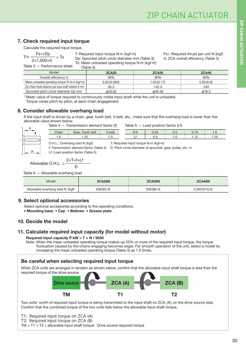
* Mean value of torque required to continuously rotate input shaft while the unit is unloaded.
Torque varies pitch by pitch, at each chain engagement.
7. Check required input torque
If the input shaft is driven by a chain, gear, tooth belt, V-belt, etc., make sure that the overhang load is lower than the allowable value shown below.
O.H.L.: Overhang load N {kgf}
f: Transmission element factor (Table 4)
Lf: Load position factor (Table 5)
T: Required input torque N·m {kgf·m}
D: Pitch circle diameter of sprocket, gear, pulley, etc. m
8. Consider allowable overhang load
Select optional accessories according to the operating conditions.
• Mounting base • Cap • Bellows • Grease plate
9. Select optional accessories
10. Decide the model
Required input capacity P kW = T × N / 9550Note: When the mean unloaded operating torque makes up 25% or more of the required input torque, the torque
fluctuation caused by the chains engaging becomes larger. For smooth operation of the unit, select a model by increasing the mean unloaded operating torque (Table 3) as 1.5 times.
11. Calculate required input capacity (for model without motor)
Be careful when selecting required input torque
Gear, Tooth beltChain V-belt
1.51.0 1.25
X/A
Lf
0.25
0.9
0.5
1.0
0.75
1.15
1.0
1.25
Model
Allowable overhang load N {kgf}
ZCA25N
638{65.0} 946{96.4} 2,065{210.5}
ZCA35N ZCA45N
Model
90%0.62{0.063}
95.3
φ30.92
90%1.63{0.17}
142.9
φ46.48
Overall efficiency η* Mean unloaded operating torque To N·m {kgf·m}
Zip Chain travel distance per input shaft rotation K mm
Sprocket pitch circle diameter Dp mm
ZCA25
90%5.85{0.6}
240
φ78.0
ZCA45ZCA35
2×T×f×LfAllowable O.H.L. ≥ ―――――― D
Fs1×DpT= ―――――― + To 2×1,000×η
Calculate the required input torque.
T: Required input torque N·m {kgf·m} Fs1: Required thrust per unit N {kgf}
Dp: Sprocket pitch circle diameter mm (Table 3) η: ZCA overall efficiency (Table 3)To: Mean unloaded operating torque N·m {kgf·m}
(Table 3)
When ZCA units are arranged in tandem as shown below, confirm that the allowable input shaft torque is less than the
required torque of the drive source.
Two units’ worth of required input torque is being transmitted to the input shaft on ZCA (A) on the drive source side.
Confirm that the combined torque of the two units falls below the allowable input shaft torque.
T1: Required input torque on ZCA (A)T2: Required input torque on ZCA (B)TM = T1 + T2 < allowable input shaft torque: Drive source required torque
TM T1 T2
Drive source ZCA (A) ZCA (B)
ZIP
CH
AIN
AC
TU
AT
OR
30
ZIP CHAIN ACTUATOR Technical Data and Product Selection
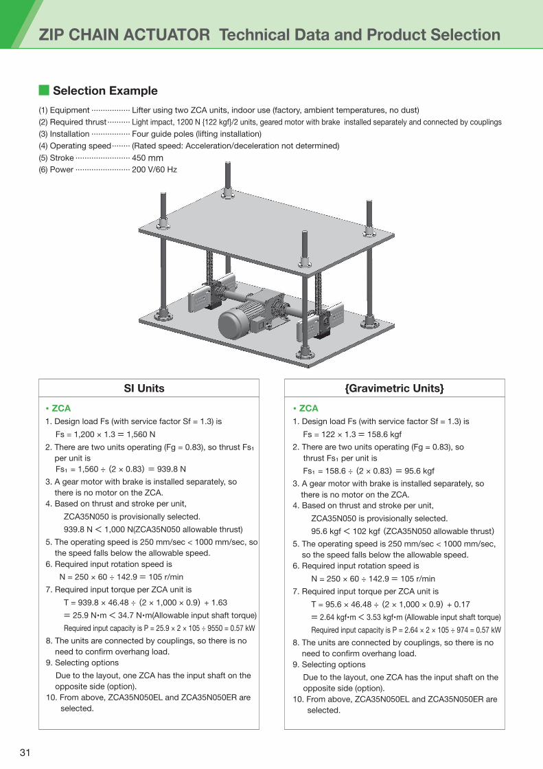
Selection Example
(1) Equipment ················· Lifter using two ZCA units, indoor use (factory, ambient temperatures, no dust)
(2) Required thrust·········· Light impact, 1200 N {122 kgf}/2 units, geared motor with brake installed separately and connected by couplings
(3) Installation ················· Four guide poles (lifting installation)
(4) Operating speed········ (Rated speed: Acceleration/deceleration not determined)
(5) Stroke ························ 450 mm(6) Power ························ 200 V/60 Hz
SI Units {Gravimetric Units}
・ ZCA
1. Design load Fs (with service factor Sf = 1.3) is
Fs = 1,200 × 1.3 = 1,560 N
2. There are two units operating (Fg = 0.83), so thrust Fs₁ per unit is Fs₁ = 1,560 ÷ (2 × 0.83) = 939.8 N
3. A gear motor with brake is installed separately, so
there is no motor on the ZCA.
4. Based on thrust and stroke per unit,
ZCA35N050 is provisionally selected.
939.8 N < 1,000 N(ZCA35N050 allowable thrust)
5. The operating speed is 250 mm/sec < 1000 mm/sec, so
the speed falls below the allowable speed.
6. Required input rotation speed is N = 250 × 60 ÷ 142.9 = 105 r/min
7. Required input torque per ZCA unit is
T = 939.8 × 46.48 ÷ (2 × 1,000 × 0.9) + 1.63
= 25.9 N・m < 34.7 N・m(Allowable input shaft torque)
Required input capacity is P = 25.9 × 2 × 105 ÷ 9550 = 0.57 kW
8. The units are connected by couplings, so there is no
need to confirm overhang load.
9. Selecting options
Due to the layout, one ZCA has the input shaft on the
opposite side (option).
10. From above, ZCA35N050EL and ZCA35N050ER are
selected.
・ ZCA
1. Design load Fs (with service factor Sf = 1.3) is
Fs = 122 × 1.3 = 158.6 kgf
2. There are two units operating (Fg = 0.83), so
thrust Fs₁ per unit is Fs₁ = 158.6 ÷ (2 × 0.83) = 95.6 kgf
3. A gear motor with brake is installed separately, so
there is no motor on the ZCA.
4. Based on thrust and stroke per unit,
ZCA35N050 is provisionally selected.
95.6 kgf < 102 kgf (ZCA35N050 allowable thrust)5. The operating speed is 250 mm/sec < 1000 mm/sec,
so the speed falls below the allowable speed.
6. Required input rotation speed is
N = 250 × 60 ÷ 142.9 = 105 r/min
7. Required input torque per ZCA unit is
T = 95.6 × 46.48 ÷ (2 × 1,000 × 0.9) + 0.17
= 2.64 kgf・m < 3.53 kgf・m (Allowable input shaft torque)
Required input capacity is P = 2.64 × 2 × 105 ÷ 974 = 0.57 kW
8. The units are connected by couplings, so there is no
need to confirm overhang load.
9. Selecting options
Due to the layout, one ZCA has the input shaft on the
opposite side (option).
10. From above, ZCA35N050EL and ZCA35N050ER are
selected.
31
ZIP CHAIN ACTUATOR
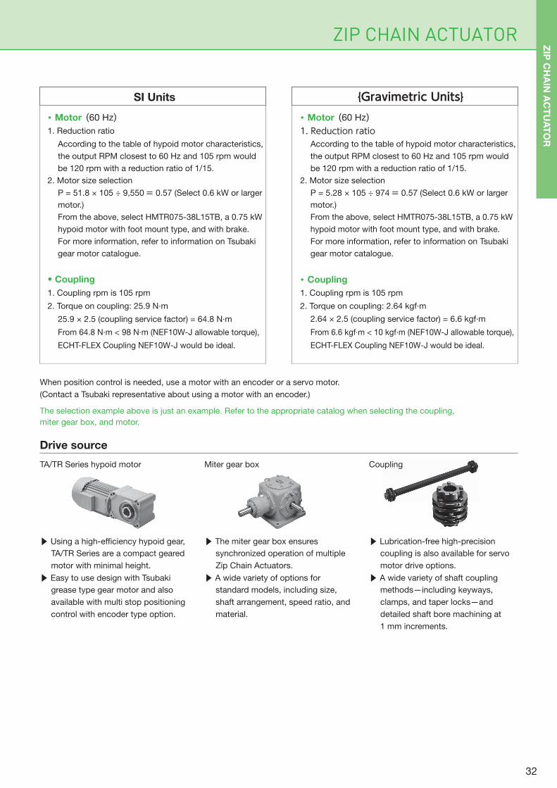
When position control is needed, use a motor with an encoder or a servo motor.
(Contact a Tsubaki representative about using a motor with an encoder.)
SI Units {Gravimetric Units}
The selection example above is just an example. Refer to the appropriate catalog when selecting the coupling,
miter gear box, and motor.
Drive source
TA/TR Series hypoid motor Miter gear box Coupling
・ Motor (60 Hz)1. Reduction ratio
According to the table of hypoid motor characteristics,
the output RPM closest to 60 Hz and 105 rpm would
be 120 rpm with a reduction ratio of 1/15.
2. Motor size selection
P = 51.8 × 10⁵ ÷ 9,550 = 0.57 (Select 0.6 kW or larger
motor.)
From the above, select HMTR075-38L15TB, a 0.75 kW
hypoid motor with foot mount type, and with brake.
For more information, refer to information on Tsubaki
gear motor catalogue.
• Coupling
1. Coupling rpm is 105 rpm
2. Torque on coupling: 25.9 N·m
25.9 × 2.5 (coupling service factor) = 64.8 N·m
From 64.8 N·m < 98 N·m (NEF10W-J allowable torque),
ECHT-FLEX Coupling NEF10W-J would be ideal.
・ Motor (60 Hz)1. Reduction ratio
According to the table of hypoid motor characteristics,
the output RPM closest to 60 Hz and 105 rpm would
be 120 rpm with a reduction ratio of 1/15.
2. Motor size selection
P = 5.28 × 10⁵ ÷ 974 = 0.57 (Select 0.6 kW or larger
motor.)
From the above, select HMTR075-38L15TB, a 0.75 kW
hypoid motor with foot mount type, and with brake.
For more information, refer to information on Tsubaki
gear motor catalogue.
・ Coupling
1. Coupling rpm is 105 rpm
2. Torque on coupling: 2.64 kgf·m
2.64 × 2.5 (coupling service factor) = 6.6 kgf·m
From 6.6 kgf·m < 10 kgf·m (NEF10W-J allowable torque),
ECHT-FLEX Coupling NEF10W-J would be ideal.
▶ Using a high-efficiency hypoid gear,
TA/TR Series are a compact geared
motor with minimal height.
▶ Easy to use design with Tsubaki
grease type gear motor and also
available with multi stop positioning
control with encoder type option.
▶ The miter gear box ensures
synchronized operation of multiple
Zip Chain Actuators.
▶ A wide variety of options for
standard models, including size,
shaft arrangement, speed ratio, and
material.
▶ Lubrication-free high-precision
coupling is also available for servo
motor drive options.
▶ A wide variety of shaft coupling
methods—including keyways,
clamps, and taper locks—and
detailed shaft bore machining at
1 mm increments.
ZIP
CH
AIN
AC
TU
AT
OR
32
P 83
A ∅12
70
319.5
C
A
27
P
B∅27
12.5
83
70
47
DC rectifier
Cover
135
98
51
∅27
ZIP CHAIN ACTUATOR Technical Data・Hypoid motor
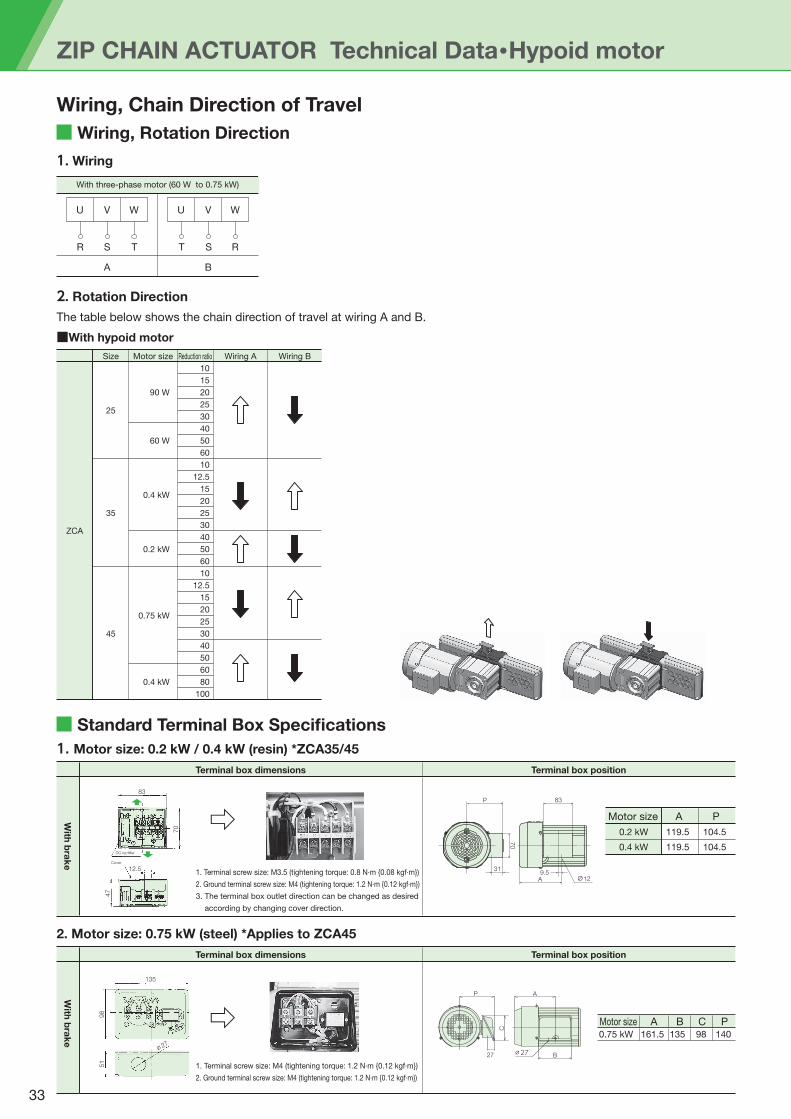
Wiring, Rotation Direction
Wiring, Chain Direction of Travel
Standard Terminal Box Specifications
2. Rotation Direction
The table below shows the chain direction of travel at wiring A and B.
1. Wiring
VU
R
A
T
W VU
TS S
B
R
W
With three-phase motor (60 W to 0.75 kW)
1. Motor size: 0.2 kW / 0.4 kW (resin) *ZCA35/45
2. Motor size: 0.75 kW (steel) *Applies to ZCA45
AMotor size P
0.2 kW 0.4 kW
119.5
119.5
104.5
104.5
Terminal box dimensions
With
bra
ke
Terminal box position
Terminal box dimensions
With
bra
ke
Terminal box position
1. Terminal screw size: M3.5 (tightening torque: 0.8 N·m {0.08 kgf·m})
2. Ground terminal screw size: M4 (tightening torque: 1.2 N·m {0.12 kgf·m})
3. The terminal box outlet direction can be changed as desired
according by changing cover direction.
⇨
1. Terminal screw size: M4 (tightening torque: 1.2 N·m {0.12 kgf·m})
2. Ground terminal screw size: M4 (tightening torque: 1.2 N·m {0.12 kgf·m})
⇨ Motor size A B C P0.75 kW 161.5 135 98 140
■With hypoid motor
25
35
45
Size Motor size Reduction ratio Wiring A Wiring B
90 W
60 W
0.4 kW
0.2 kW
0.75 kW
0.4 kW
10
15
20
25
30
40
50
60
10
12.5
15
20
25
30
40
50
60
10
12.5
15
20
25
30
40
50
60
80
100
ZCA
33
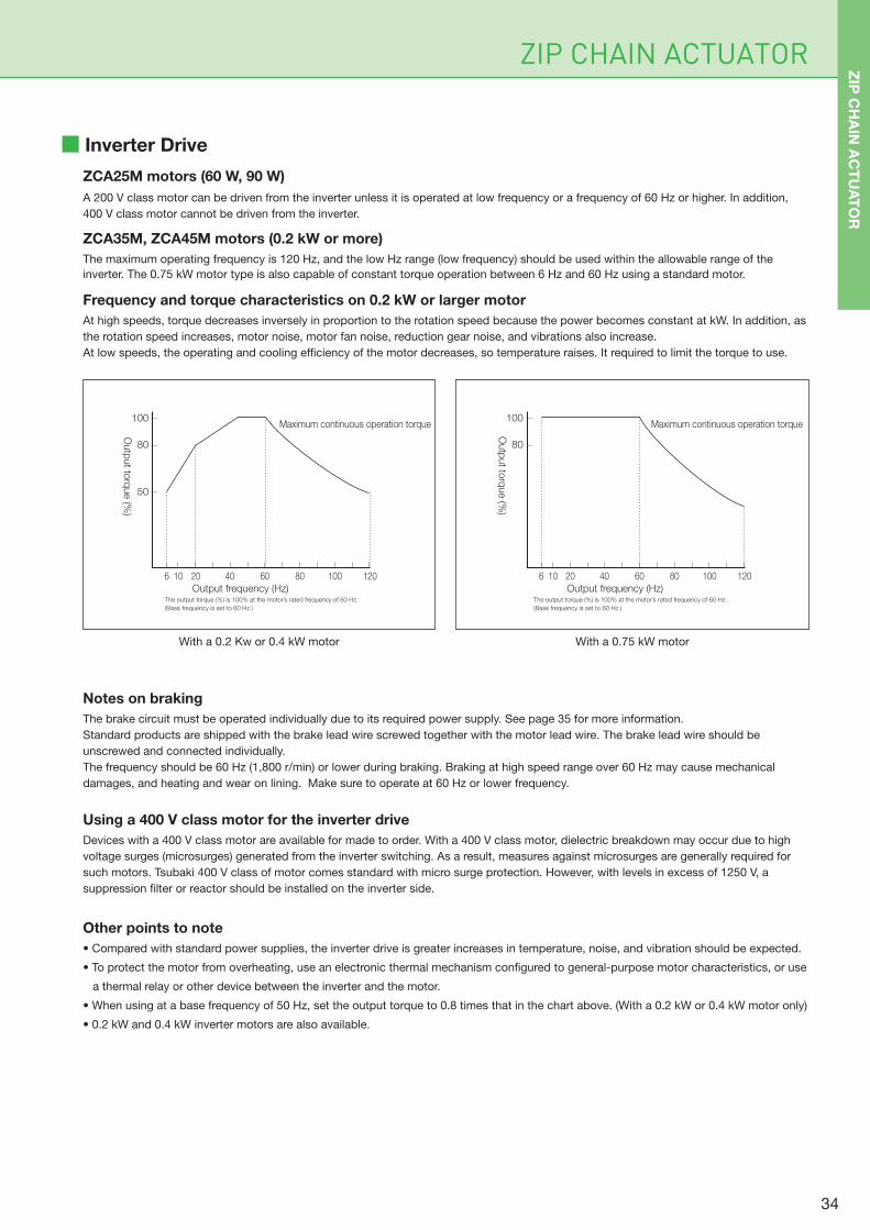
6 10 20 40 60 80 100 120
100
80
50
Maximum continuous operation torque
Output frequency (Hz)The output torque (%) is 100% at the motor’s rated frequency of 60 Hz.
(Base frequency is set to 60 Hz.)
6 10 20 40 60 80 100 120
100
80
Outp
ut to
rque (%
)
Maximum continuous operation torque
Output frequency (Hz)The output torque (%) is 100% at the motor’s rated frequency of 60 Hz.
(Base frequency is set to 60 Hz.)
Outp
ut to
rque (%
)
ZIP CHAIN ACTUATOR
Inverter Drive
ZCA25M motors (60 W, 90 W)
A 200 V class motor can be driven from the inverter unless it is operated at low frequency or a frequency of 60 Hz or higher. In addition,
400 V class motor cannot be driven from the inverter.
ZCA35M, ZCA45M motors (0.2 kW or more)
The maximum operating frequency is 120 Hz, and the low Hz range (low frequency) should be used within the allowable range of the
inverter. The 0.75 kW motor type is also capable of constant torque operation between 6 Hz and 60 Hz using a standard motor.
Frequency and torque characteristics on 0.2 kW or larger motor
At high speeds, torque decreases inversely in proportion to the rotation speed because the power becomes constant at kW. In addition, as
the rotation speed increases, motor noise, motor fan noise, reduction gear noise, and vibrations also increase.
At low speeds, the operating and cooling efficiency of the motor decreases, so temperature raises. It required to limit the torque to use.
Notes on braking
The brake circuit must be operated individually due to its required power supply. See page 35 for more information.
Standard products are shipped with the brake lead wire screwed together with the motor lead wire. The brake lead wire should be
unscrewed and connected individually.
The frequency should be 60 Hz (1,800 r/min) or lower during braking. Braking at high speed range over 60 Hz may cause mechanical
damages, and heating and wear on lining. Make sure to operate at 60 Hz or lower frequency.
Using a 400 V class motor for the inverter drive
Devices with a 400 V class motor are available for made to order. With a 400 V class motor, dielectric breakdown may occur due to high
voltage surges (microsurges) generated from the inverter switching. As a result, measures against microsurges are generally required for
such motors. Tsubaki 400 V class of motor comes standard with micro surge protection. However, with levels in excess of 1250 V, a
suppression filter or reactor should be installed on the inverter side.
Other points to note
• Compared with standard power supplies, the inverter drive is greater increases in temperature, noise, and vibration should be expected.
• To protect the motor from overheating, use an electronic thermal mechanism configured to general-purpose motor characteristics, or use
a thermal relay or other device between the inverter and the motor.
• When using at a base frequency of 50 Hz, set the output torque to 0.8 times that in the chart above. (With a 0.2 kW or 0.4 kW motor only)
• 0.2 kW and 0.4 kW inverter motors are also available.
With a 0.2 Kw or 0.4 kW motor With a 0.75 kW motor
ZIP
CH
AIN
AC
TU
AT
OR
34
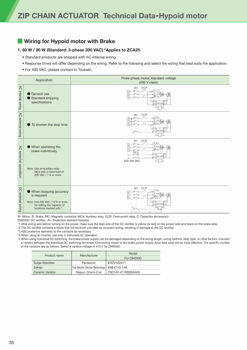
ZIP CHAIN ACTUATOR Technical Data・Hypoid motor
Wiring for Hypoid motor with Brake
1. 60 W / 90 W (Standard: 3-phase 200 VAC) *Applies to ZCA25
Application
● General use
● Standard shipping
specifications
● To shorten the stop time
● When operating the
brake individually
● When stopping accuracy is required
Note: Use an auxiliary relay
MCa with a rated load of
200 VAC / 7 A or more.
Note: Use 200 VAC / 10 A or more
for setting the capacity of
locations marked with *.
Three-phase motor, standard voltage
(200 V class)
200–220 VAC
AC
inte
rnal w
iring
AC
exte
rnal w
iring
AC
exte
rnal o
pera
tion
DC
exte
rnal w
iring
Ⓜ: Motor, Ⓑ: Brake, MC: Magnetic contactor, MCa: Auxiliary relay, OCR: Overcurrent relay, C: Capacitor (accessory)
DM200D: DC rectifier, -N-: Protection element (varistor)
*1 After wiring and before turning on the power, make sure the lead wire of the DC rectifier is yellow (or red) on the power side and black on the brake side.
*2 The DC rectifier contains a diode that will be short-circuited by incorrect wiring, resulting in damage to the DC rectifier.
*3 Add protective elements to the contacts as necessary.
*4 When using an inverter, use only in individual AC operation.
*5 When using individual DC switching, the brake power supply can be damaged depending on the wiring length, wiring method, relay type, or other factors. Connect
a varistor between the individual DC switching terminals. Connecting closer to the brake power supply (blue lead wire) will be most effective. The specific models
of the varistors are as follows. Select a varistor voltage of 470 V for DM200D.
Product name
Surge Absorber
Zetrap
Ceramic Varistor
Panasonic
Fuji Electric Device Technology
Nippon Chemi-Con
ERZV14D471
ENE471D-14A
TND14V-471KB00AAA0
ManufacturerModel
For DM200D
Black
Black
Black
Gray
Yellow
Yellow
Blue Blue
White
Black
Gray
White
Black
Black
Yellow
Yellow
Blue Blue
N
Black
Gray
White
Black
Black
Yellow
Yellow
Blue Blue
• Standard products are shipped with AC internal wiring.
• Response times will differ depending on the wiring. Refer to the following and select the wiring that best suits the application.
• For 400 VAC, please contact to Tsubaki.
Po
wer s
ourc
eP
ow
er s
ourc
eP
ow
er s
ourc
eP
ow
er s
ourc
e
Black
Gray
White
Black
Black
Yellow
Yellow
Blue Blue
35
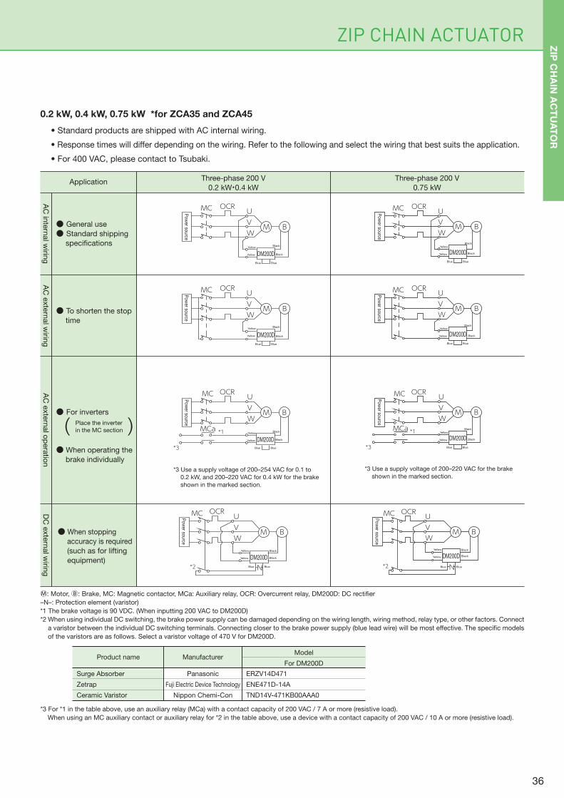
ZIP CHAIN ACTUATOR
Ⓜ: Motor, Ⓑ: Brake, MC: Magnetic contactor, MCa: Auxiliary relay, OCR: Overcurrent relay, DM200D: DC rectifier
–N–: Protection element (varistor)
*1 The brake voltage is 90 VDC. (When inputting 200 VAC to DM200D)
*2 When using individual DC switching, the brake power supply can be damaged depending on the wiring length, wiring method, relay type, or other factors. Connect
a varistor between the individual DC switching terminals. Connecting closer to the brake power supply (blue lead wire) will be most effective. The specific models
of the varistors are as follows. Select a varistor voltage of 470 V for DM200D.
*3 For *1 in the table above, use an auxiliary relay (MCa) with a contact capacity of 200 VAC / 7 A or more (resistive load).
When using an MC auxiliary contact or auxiliary relay for *2 in the table above, use a device with a contact capacity of 200 VAC / 10 A or more (resistive load).
Product name
Surge Absorber
Zetrap
Ceramic Varistor
Panasonic
Fuji Electric Device Technology
Nippon Chemi-Con
ERZV14D471
ENE471D-14A
TND14V-471KB00AAA0
ManufacturerModel
For DM200D
0.2 kW, 0.4 kW, 0.75 kW *for ZCA35 and ZCA45
● General use
● Standard shipping
specifications
● To shorten the stop
time
● For inverters
● When operating the
brake individually
● When stopping
accuracy is required
(such as for lifting
equipment)
AC
inte
rnal w
iring
AC
exte
rnal w
iring
AC
exte
rnal o
pera
tion
DC
exte
rnal w
iring
ApplicationThree-phase 200 V
0.2 kW・0.4 kW
Three-phase 200 V
0.75 kW
( )
*2
*3 Use a supply voltage of 200–254 VAC for 0.1 to
0.2 kW, and 200–220 VAC for 0.4 kW for the brake
shown in the marked section.
*1
*3
MC OCR
MCa
UVW
M B
DM200D
Po
wer so
urce
BlackYellow
Yellow
Blue Blue
Black Black
Black
Black
Black
DM200D
MC OCR UVW
M
DM200D
B
Po
wer so
urce
Black
Black
Yellow
Yellow
Blue Blue
DM200D
Po
wer so
urce
Black
Yellow
Yellow
Blue Blue
MC OCR UVW
M B
N
MC OCRUVW
M B
Place the inverter
in the MC section
*3 Use a supply voltage of 200–220 VAC for the brake
shown in the marked section.
*2
*1
*3
MC OCR
MCa
UVW
M B
MC OCR UVW
M B
MC OCR UVW
M B
DM200D
Po
wer so
urce
BlackYellow
Yellow
Blue Blue
DM200D
Po
wer so
urce
BlackYellow
Yellow
Blue Blue
N
MC OCR UVW
M B
DM200D
Po
wer so
urce
BlackYellow
Yellow
Blue Blue
Black
• Standard products are shipped with AC internal wiring.
• Response times will differ depending on the wiring. Refer to the following and select the wiring that best suits the application.
• For 400 VAC, please contact to Tsubaki.
DM200D
Po
wer so
urce
Black
Yellow
Yellow
Blue Blue
Po
wer so
urce
Black
Black
Yellow
Yellow
Blue Blue
ZIP
CH
AIN
AC
TU
AT
OR
36
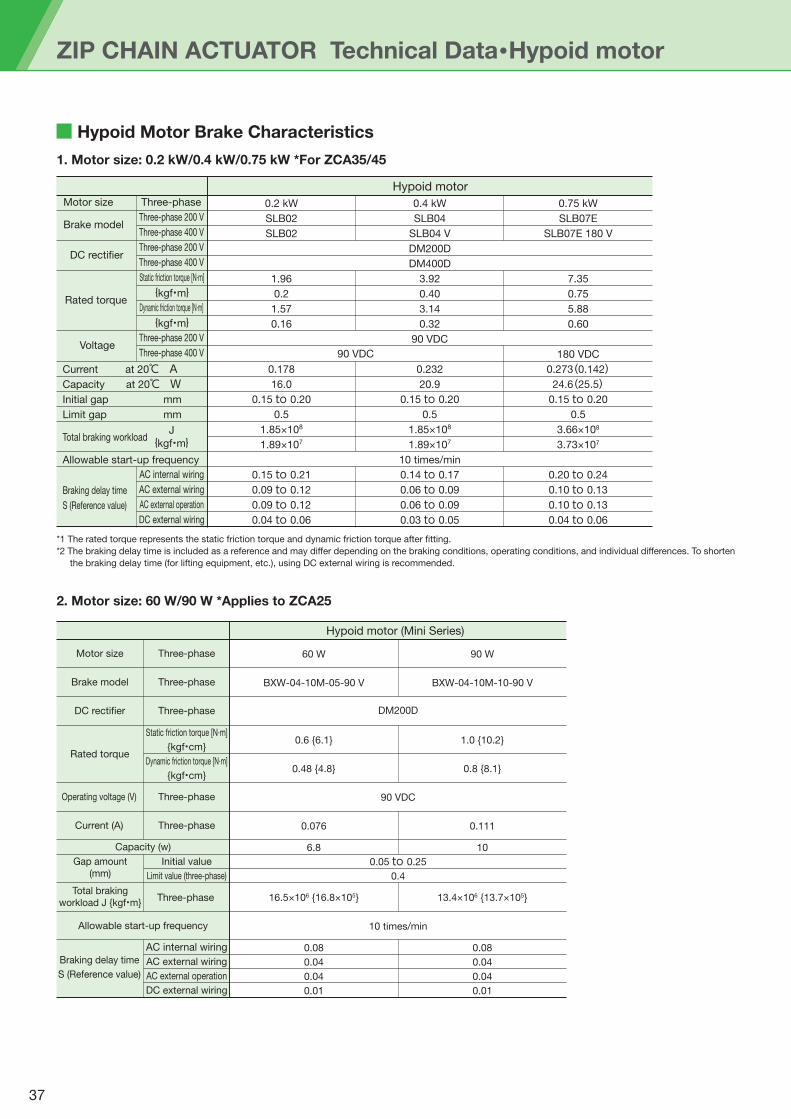
ZIP CHAIN ACTUATOR Technical Data・Hypoid motor
Hypoid Motor Brake Characteristics
1. Motor size: 0.2 kW/0.4 kW/0.75 kW *For ZCA35/45
2. Motor size: 60 W/90 W *Applies to ZCA25
*1 The rated torque represents the static friction torque and dynamic friction torque after fitting.
*2 The braking delay time is included as a reference and may differ depending on the braking conditions, operating conditions, and individual differences. To shorten
the braking delay time (for lifting equipment, etc.), using DC external wiring is recommended.
0.2 kW
SLB02
SLB02
1.96
0.2
1.57
0.16
0.178
16.0
0.15 to 0.20
0.5
1.85×10⁸
1.89×10⁷
0.15 to 0.21
0.09 to 0.12
0.09 to 0.12
0.04 to 0.06
Current at 20℃ ACapacity at 20℃ WInitial gap mm
Limit gap mm
Total braking workload
Allowable start-up frequency
AC internal wiring
AC external wiring
AC external operation
DC external wiring
0.4 kW
SLB04
SLB04 V
DM200D
DM400D
3.92
0.40
3.14
0.32
90 VDC
0.232
20.9
0.15 to 0.20
0.5
1.85×10⁸
1.89×10⁷
10 times/min
0.14 to 0.17
0.06 to 0.09
0.06 to 0.09
0.03 to 0.05
0.75 kW
SLB07E
SLB07E 180 V
7.35
0.75
5.88
0.60
180 VDC
0.273(0.142)24.6(25.5)
0.15 to 0.20
0.5
3.66×10⁸
3.73×10⁷
0.20 to 0.24
0.10 to 0.13
0.10 to 0.13
0.04 to 0.06
Hypoid motor
J
{kgf・m}
Static friction torque [N·m]
{kgf・cm}
Dynamic friction torque [N·m]
{kgf・cm}
Three-phase
Three-phase
Three-phase
Three-phase
Three-phase
Rated torque
Operating voltage (V)
Current (A)
Initial value
Limit value (three-phase)
Gap amount(mm)
Total braking workload J {kgf・m}
Motor size
Brake model
DC rectifier
Braking delay time
S (Reference value)
AC internal wiring
AC external wiring
AC external operation
DC external wiring
BXW-04-10M-05-90 V BXW-04-10M-10-90 V
0.6 {6.1}
0.48 {4.8}
1.0 {10.2}
0.8 {8.1}
0.076
6.8
0.111
10
16.5×10⁶ {16.8×10⁵} 13.4×10⁶ {13.7×10⁵}
0.08
0.04
0.04
0.01
0.08
0.04
0.04
0.01
Hypoid motor (Mini Series)
Capacity (w)
Allowable start-up frequency
60 W
DM200D
90 VDC
0.05 to 0.25
0.4
10 times/min
90 W
90 VDC
Motor size
Brake model
DC rectifier
Rated torque
Braking delay time
S (Reference value)
Voltage
Three-phase
Three-phase 200 V
Three-phase 200 V
Three-phase 400 V
Three-phase 400 V
Three-phase 200 V
Three-phase 400 V
Static friction torque [N·m]
{kgf・m}
{kgf・m}Dynamic friction torque [N·m]
Three-phase
37
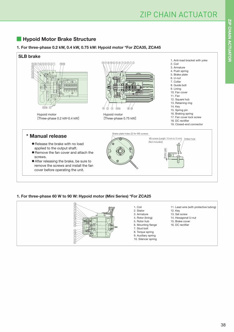
ZIP CHAIN ACTUATOR
Hypoid Motor Brake Structure
1. For three-phase 0.2 kW, 0.4 kW, 0.75 kW: Hypoid motor *For ZCA35, ZCA45
1. For three-phase 60 W to 90 W: Hypoid motor (Mini Series) *For ZCA25
SLB brake
Hypoid motor
[Three-phase 0.2 kW・0.4 kW]Hypoid motor
[Three-phase 0.75 kW]
1. Anti-load bracket with yoke
2. Coil
3. Armature
4. Push spring
5. Brake plate
6. U-nut
7. Collar
8. Guide bolt
9. Lining
10. Fan cover
11. Fan
12. Square hub
13. Retaining ring
14. Key
15. Spring pin
16. Braking spring
17. Fan cover lock screw
18. DC rectifier
19. Closed-end connector
11. Lead wire (with protective tubing)
12. Key
13. Set screw
14. Hexagonal U-nut
15. Brake cover
16. DC rectifier
1. Coil
2. Stator
3. Armature
4. Rotor (lining)
5. Rotor hub
6. Mounting flange
7. Stud bolt
8. Torque spring
9. Auxiliary spring
10. Silencer spring
* Manual release
●Release the brake with no load
applied to the output shaft.
●Remove the fan cover and attach the
screws.
●After releasing the brake, be sure to
remove the screws and install the fan
cover before operating the unit.
①⑨⑩⑪⑫⑬⑭
⑧⑦⑥⑤④③②
⑮⑯ ⑰
⑱⑲
⑭ ⑨⑫ ⑮⑯ ⑱⑲
⑬⑪⑧⑩⑥⑤④⑦③⑰①②
WV
E
U
Brake plate holes (2) for M5 screws
M5 screws (Length: 10 mm to 15 mm)
(Not included)
Drilled hole
Bra
ke g
ap
ZIP
CH
AIN
AC
TU
AT
OR
38
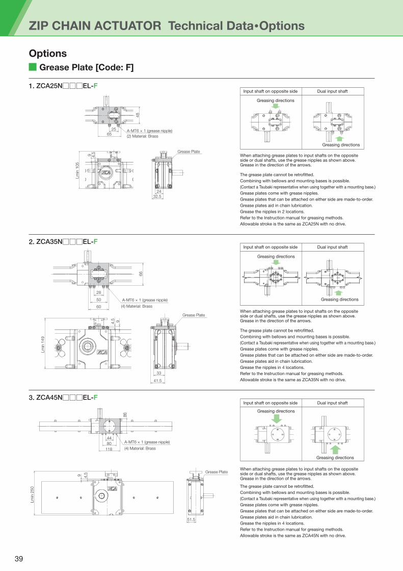
ZIP CHAIN ACTUATOR Technical Data・Options
Grease Plate [Code: F]
1. ZCA25N□□□EL-F
Options
2. ZCA35N□□□EL-F
3. ZCA45N□□□EL-F
A-MT6 × 1 (grease nipple)25
48
65(2) Material: Brass
Grease Plate
32.5
24
4.5
Lm
in 1
05
9
4.5
Lm
in 1
49
9
(4) Material: Brass
A-MT6 × 1 (grease nipple)50
66
28
60
Grease Plate
41.5
33
Input shaft on opposite side
Greasing directions
Greasing directions
Dual input shaft
The grease plate cannot be retrofitted.
Combining with bellows and mounting bases is possible.
(Contact a Tsubaki representative when using together with a mounting base.)
Grease plates come with grease nipples.
Grease plates that can be attached on either side are made-to-order.
Grease plates aid in chain lubrication.
Grease the nipples in 2 locations.
Refer to the Instruction manual for greasing methods.
Allowable stroke is the same as ZCA25N with no drive.
When attaching grease plates to input shafts on the opposite side or dual shafts, use the grease nipples as shown above. Grease in the direction of the arrows.
Input shaft on opposite side
Greasing directions
Greasing directions
Dual input shaft
Input shaft on opposite side
Greasing directions
Greasing directions
Dual input shaft
The grease plate cannot be retrofitted.
Combining with bellows and mounting bases is possible.
(Contact a Tsubaki representative when using together with a mounting base.)
Grease plates come with grease nipples.
Grease plates that can be attached on either side are made-to-order.
Grease plates aid in chain lubrication.
Grease the nipples in 4 locations.
Refer to the Instruction manual for greasing methods.
Allowable stroke is the same as ZCA35N with no drive.
When attaching grease plates to input shafts on the opposite side or dual shafts, use the grease nipples as shown above. Grease in the direction of the arrows.
Lm
in 2
50
9 4.5
A-MT6 × 1 (grease nipple)
(4) Material: Brass
44
80
118
86
The grease plate cannot be retrofitted.
Combining with bellows and mounting bases is possible.
(Contact a Tsubaki representative when using together with a mounting base.)
Grease plates come with grease nipples.
Grease plates that can be attached on either side are made-to-order.
Grease plates aid in chain lubrication.
Grease the nipples in 4 locations.
Refer to the Instruction manual for greasing methods.
Allowable stroke is the same as ZCA45N with no drive.
When attaching grease plates to input shafts on the opposite side or dual shafts, use the grease nipples as shown above. Grease in the direction of the arrows.
Grease Plate
51.5
39
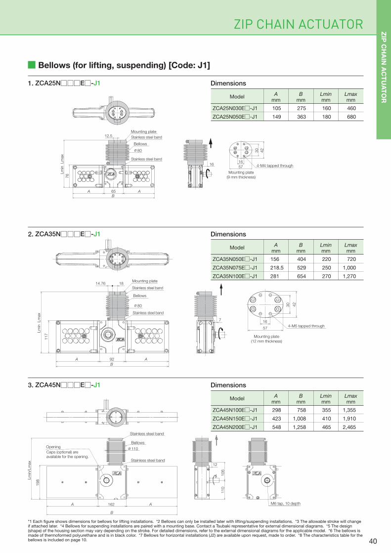
ZIP CHAIN ACTUATOR
Bellows (for lifting, suspending) [Code: J1]
1. ZCA25N□□□E□-J1
2. ZCA35N□□□E□-J1
3. ZCA45N□□□E□-J1
A 162 A
B
198
Lm
in/L
max
Opening
Caps (optional) are available for the opening.
Stainless steel band
Stainless steel band
Bellows
∅110
12
M6 tap, 10 depth
110
106
Bellows
Mounting plate
Stainless steel band
Stainless steel band
Lm
in
Lm
ax
76
65A AB
12.5
16
Mounting plate
(9 mm thickness)
57
42
30
164-M4 tapped through
∅80
Mounting plate
(12 mm thickness)
16
57
42
30
4-M5 tapped through
7
Mounting plate
Stainless steel band
Bellows
Stainless steel band
∅80
BA
18
117
Lm
in Lm
ax
A 92
14.76
ZCA25N030E□-J1
ZCA25N050E□-J1
105
149
275
363
160
180
460
680
ModelB
mmLminmm
Lmaxmm
Amm
Dimensions
ZCA35N050E□-J1
ZCA35N075E□-J1
ZCA35N100E□-J1
156
218.5
281
404
529
654
220
250
270
720
1,000
1,270
ModelB
mmLminmm
Lmaxmm
Amm
Dimensions
ZCA45N100E□-J1
ZCA45N150E□-J1
ZCA45N200E□-J1
758
1,008
1,258
298
423
548
355
410
465
1,355
1,910
2,465
ModelB
mmLminmm
Lmaxmm
Amm
Dimensions
*1 Each figure shows dimensions for bellows for lifting installations. *2 Bellows can only be installed later with lifting/suspending installations. *3 The allowable stroke will change if attached later. *4 Bellows for suspending installations are paired with a mounting base. Contact a Tsubaki representative for external dimensional diagrams. *5 The design (shape) of the housing section may vary depending on the stroke. For detailed dimensions, refer to the external dimensional diagrams for the applicable model. *6 The bellows is made of thermoformed polyurethane and is in black color. *7 Bellows for horizontal installations (J2) are available upon request, made to order. *8 The characteristics table for the bellows is included on page 10.
ZIP
CH
AIN
AC
TU
AT
OR
40
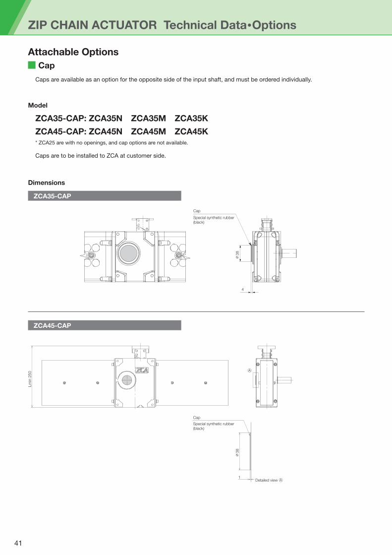
ZIP CHAIN ACTUATOR Technical Data・Options
Cap
Attachable Options
Caps are available as an option for the opposite side of the input shaft, and must be ordered individually.
Model
ZCA35-CAP: ZCA35N ZCA35M ZCA35K
ZCA45-CAP: ZCA45N ZCA45M ZCA45K* ZCA25 are with no openings, and cap options are not available.
Caps are to be installed to ZCA at customer side.
ZCA35-CAP
Dimensions
ZCA45-CAP
∅38
4
Cap
Special synthetic rubber (black)
Cap
Special synthetic rubber (black)
Detailed view Ⓐ1
Ⓐ
Lm
in 2
50
∅38
41
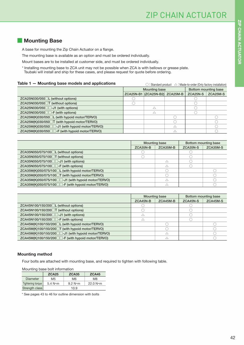
ZIP CHAIN ACTUATOR
Mounting Base
A base for mounting the Zip Chain Actuator on a flange.
The mounting base is available as an option and must be ordered individually.
Mount bases are to be installed at customer side, and must be ordered individually.
* Installing mounting base to ZCA unit may not be possible when ZCA is with bellows or grease plate. Tsubaki will install and ship for these cases, and please request for quote before ordering.
Mounting method
Four bolts are attached with mounting base, and required to tighten with following table.
Mounting base bolt information
Table 1 — Mounting base models and applications
Mounting base Bottom mounting base
ZCA25N030/050□L (without options)
ZCA25N030/050□T (without options)
ZCA25N030/050□□-J1 (with options)
ZCA25N030/050□□-F (with options)
ZCA25M(K)030/050□L (with hypoid motor/TERVO)
ZCA25M(K)030/050□T (with hypoid motor/TERVO)
ZCA25M(K)030/050□□-J1 (with hypoid motor/TERVO)
ZCA25M(K)030/050□□-F (with hypoid motor/TERVO)
Mounting base Bottom mounting base
ZCA35N050/075/100□L (without options)
ZCA35N050/075/100□T (without options)
ZCA35N050/075/100□□-J1 (with options)
ZCA35N050/075/100□□-F (with options)
ZCA35M(K)050/075/100□L (with hypoid motor/TERVO)
ZCA35M(K)050/075/100□T (with hypoid motor/TERVO)
ZCA35M(K)050/075/100□□-J1 (with hypoid motor/TERVO)
ZCA35M(K)050/075/100□□-F (with hypoid motor/TERVO)
Mounting base Bottom mounting base
ZCA45N-B
○○△△
ZCA45M-B
○○△△
ZCA45N-S
○○○○
ZCA45M-S
○○○○
ZCA45N100/150/200□L (without options)
ZCA45N100/150/200□T (without options)
ZCA45N100/150/200□□-J1 (with options)
ZCA45N100/150/200□□-F (with options)
ZCA45M(K)100/150/200□L (with hypoid motor/TERVO)
ZCA45M(K)100/150/200□T (with hypoid motor/TERVO)
ZCA45M(K)100/150/200□□-J1 (with hypoid motor/TERVO)
ZCA45M(K)100/150/200□□-F (with hypoid motor/TERVO)
* See pages 43 to 46 for outline dimension with bolts
ZCA25
M5
5.4 N・m
Diameter
Tightening torque
Strength class
ZCA35
M6
9.2 N・m
10.9
ZCA45
M8
22.0 N・m
○ : Standard product △ : Made-to-order (Only factory installation)
ZCA25N-B1
○○
(ZCA25N-B2)
△△
ZCA25M-B
○○△△
ZCA25N-S
○○○○
ZCA25M-S
○○○○
ZCA35N-B
○○
ZCA35M-B
△△○○△△
ZCA35N-S
○○○○
ZCA35M-S
○○○○
ZIP
CH
AIN
AC
TU
AT
OR
42

ZIP CHAIN ACTUATOR Technical Data・Options
ZCA25 Mounting Base
ZCA25N-B1 (without options)
Attachable Options
ZCA25N-B2 (with options)
ZCA25M-B (with hypoid motor)
Dimension is for ZCA25N030-□S, and ZCA25N050
housing section dimension is not the same.
300
500
105
149
275
363
105
105
405
505
Bmm
Lminmm
Lmaxmm
300
500
Allowable strokemm
Amm
Strokemm
Dimensions
300
500
105
149
275
363
169
169
469
669
Bmm
Lminmm
Lmaxmm
300
500
Allowable strokemm
Amm
Strokemm
Dimensions
300
500
105
149
275
363
110
110
410
610
Bmm
Lminmm
Lmaxmm
300
500
Allowable strokemm
Amm
Strokemm
Dimensions
* The effective stroke will be shortened when retrofitting.
(ST300 Lmax:405 mm Allowable stroke: 295 mm, ST500 Lmax:605 mm Allowable stroke: 495 mm)
A 65 AB
76
9
Lm
in105/L
max
9.31 12.540
5265
4-∅5.5
63
76
12.59.31
76
9
Lm
in169/L
max
40
A 65 AB
108
121
4-∅5.5
63
76
Lm
in110/L
max
676
12.5
12
A 65 AB
Lead wire
187
200
50
63
4-∅5.5 74 113
43
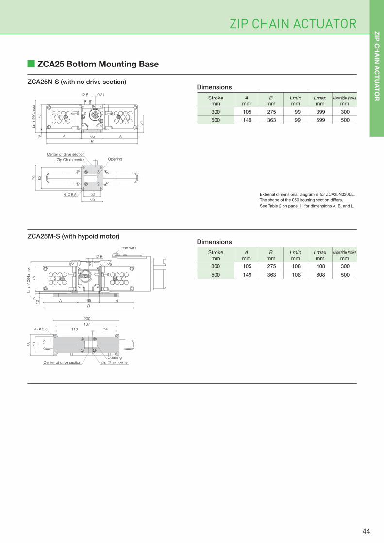
ZIP CHAIN ACTUATOR
ZCA25 Bottom Mounting Base
ZCA25N-S (with no drive section)
ZCA25M-S (with hypoid motor)
External dimensional diagram is for ZCA25N030DL.
The shape of the 050 housing section differs.
See Table 2 on page 11 for dimensions A, B, and L.
300
500
105
149
275
363
99
99
399
599
Bmm
Lminmm
Lmaxmm
300
500
Allowable strokemm
Amm
Strokemm
Dimensions
300
500
105
149
275
363
108
108
408
608
Bmm
Lminmm
Lmaxmm
300
500
Allowable strokemm
Amm
Strokemm
Dimensions
ZIP
CH
AIN
AC
TU
AT
OR12.5 9.31
54
76
9
Lm
in99/L
max
A 65 AB
52
65
63
76
4-∅5.5
OpeningZip Chain center
Center of drive section
50
63
187
200
4-∅5.5 113 74
Opening
Zip Chain centerCenter of drive section
Lm
in108/L
max
12.5
76
612 A 65 A
B
Lead wire
44
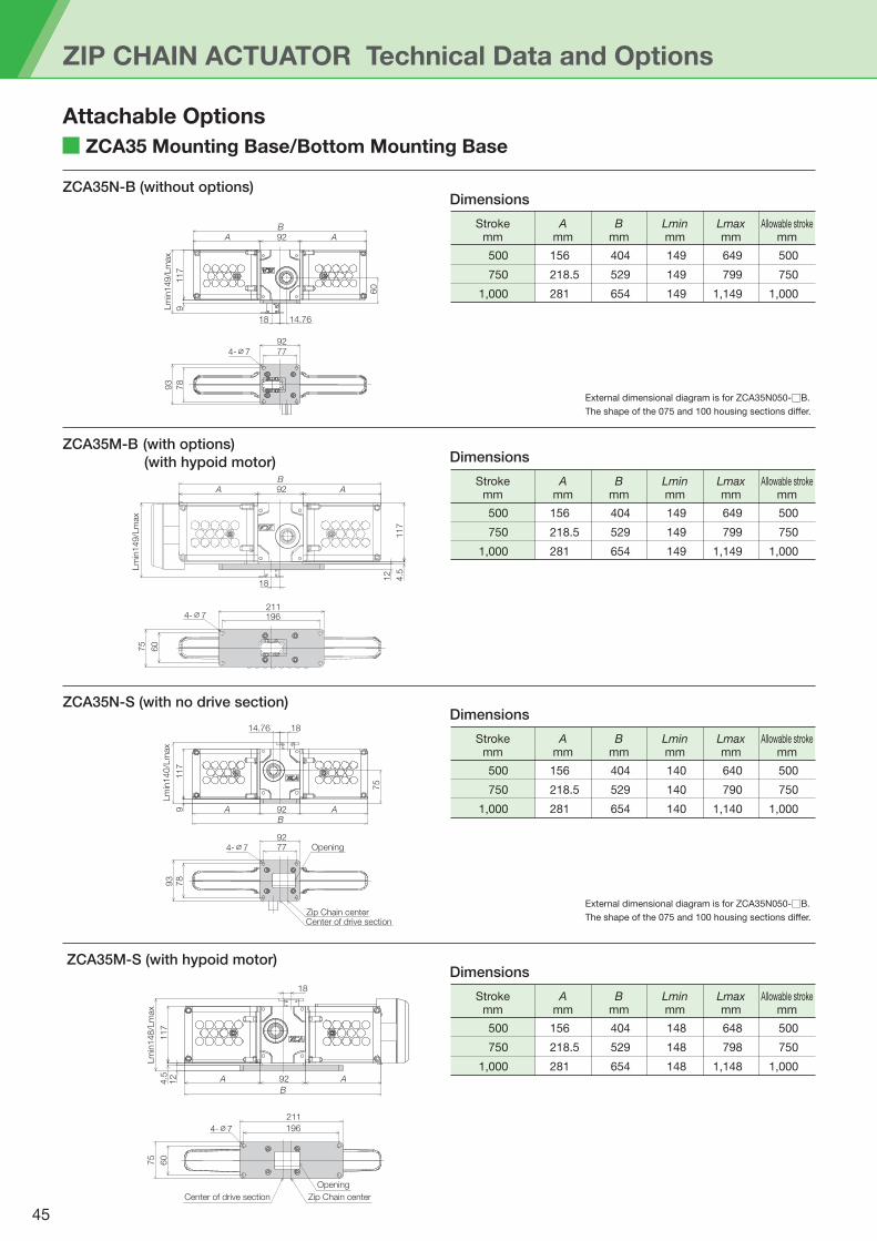
ZIP CHAIN ACTUATOR Technical Data and Options
ZCA35 Mounting Base/Bottom Mounting Base
ZCA35N-B (without options)
Attachable Options
ZCA35M-B (with options)
(with hypoid motor)
ZCA35N-S (with no drive section)
ZCA35M-S (with hypoid motor)
External dimensional diagram is for ZCA35N050-□B.
The shape of the 075 and 100 housing sections differ.
External dimensional diagram is for ZCA35N050-□B.
The shape of the 075 and 100 housing sections differ.
500
750
1,000
156
218.5
281
404
529
654
149
149
149
649
799
1,149
Bmm
Lminmm
Lmaxmm
500
750
1,000
Allowable strokemm
Amm
Strokemm
Dimensions
500
750
1,000
156
218.5
281
404
529
654
149
149
149
649
799
1,149
Bmm
Lminmm
Lmaxmm
500
750
1,000
Allowable strokemm
Amm
Strokemm
Dimensions
500
750
1,000
156
218.5
281
404
529
654
140
140
140
640
790
1,140
Bmm
Lminmm
Lmaxmm
500
750
1,000
Allowable strokemm
Amm
Strokemm
Dimensions
500
750
1,000
156
218.5
281
404
529
654
148
148
148
648
798
1,148
Bmm
Lminmm
Lmaxmm
500
750
1,000
Allowable strokemm
Amm
Strokemm
Dimensions
A92AB
Lm
in149/L
max
9117
18 14.76
60
77
78
93
924-∅7
A92AB
117
Lm
in149/L
max
18
4.5
12
75
60
2111964-∅7
Lm
in140/L
max
9117
14.76 18
75
A 92 AB
7792
78
93
4-∅7 Opening
Zip Chain centerCenter of drive section
Lm
in148/L
max
18
12
4.5
117
A 92 AB
211
60
75
4-∅7 196
Opening
Zip Chain centerCenter of drive section
45
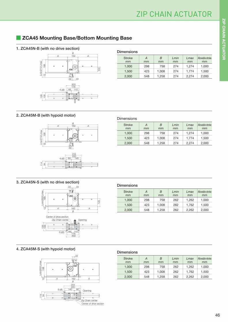
ZIP CHAIN ACTUATOR
ZCA45 Mounting Base/Bottom Mounting Base
1. ZCA45N-B (with no drive section)
2. ZCA45M-B (with hypoid motor)
3. ZCA45N-S (with no drive section)
4. ZCA45M-S (with hypoid motor)
1,000
1,500
2,000
758
1,008
1,258
298
423
548
274
274
274
1,274
1,774
2,274
Bmm
Lminmm
Lmaxmm
1,000
1,500
2,000
Allowable strokemm
Amm
Strokemm
Dimensions
1,000
1,500
2,000
758
1,008
1,258
298
423
548
274
274
274
1,274
1,774
2,274
Bmm
Lminmm
Lmaxmm
1,000
1,500
2,000
Allowable strokemm
Amm
Strokemm
Dimensions
1,000
1,500
2,000
758
1,008
1,258
298
423
548
262
262
262
1,262
1,762
2,262
Bmm
Lminmm
Lmaxmm
1,000
1,500
2,000
Allowable strokemm
Amm
Strokemm
Dimensions
1,000
1,500
2,000
758
1,008
1,258
298
423
548
262
262
262
1,262
1,762
2,262
Bmm
Lminmm
Lmaxmm
1,000
1,500
2,000
Allowable strokemm
Amm
Strokemm
Dimensions
ZIP
CH
AIN
AC
TU
AT
ORA 162 A
B
198
12Lm
in274/L
max
22
100
33
66 110
200176
106
126
4-ø9
Lm
in274/L
max
162 AAB
198
12
22
80 140220244
94
114
4-ø9
22 33
198
12
Lm
in262/L
max
122
200
106
126
4-ø9176
66 110
Zip Chain center
Center of drive section
Opening
Lm
in262/L
max
198
162A AB
22
12
140 80220244
94
114
4-ø9 Opening
Zip Chain center
Center of drive section
A 162 AB
46
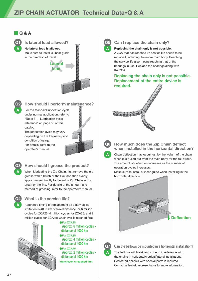
Is lateral load allowed?
No lateral load is allowed.
Make sure to install a linear guide
in the direction of travel.
How should I perform maintenance?
A
Q2
A
Q1 Can I replace the chain only?
Replacing the chain only is not possible.
A ZCA that has reached its service life needs to be
replaced, including the entire main body. Reaching
the service life also means reaching that of the
bearings in use. Replace the bearings along with
the ZCA.
A
Q5
Can the bellows be mounted in a horizontal installation?
The bellows will break early due to interference with
the chains in horizontal/vertical/lateral installations.
Dedicated bellows with special parts is required.
Contact a Tsubaki representative for more information.
A
Q7
How much does the Zip Chain deflect when installed in the horizontal direction?
Chain deflection may occur just by the weight of the chain
when it is pulled out from the main body for the full stroke.
The amount of deflection increases as the number of
operation cycles increases.
Make sure to install a linear guide when installing in the
horizontal direction.
A
Q6
For the standard lubrication cycle
under normal application, refer to
“Table 3 — Lubrication cycle
reference” on page 50 of this
catalog.
The lubrication cycle may vary
depending on the frequency and
condition of usage.
For details, refer to the
operator’s manual.
How should I grease the product?
A
Q3
When lubricating the Zip Chain, first remove the old
grease with a brush or the like, and then evenly
apply grease directly to the entire Zip Chain with a
brush or the like. For details of the amount and
method of greasing, refer to the operator’s manual.
What is the service life?
A
Q4
Reference timing of replacement as a service life
limitation is 4000 km of travel distance, or 6 million
cycles for ZCA25, 4 million cycles for ZCA35, and 2
million cycles for ZCA45; whichever is reached first.
●For ZCA25:
Approx. 6 million cycles or distance of 4000 km●For ZCA35:
Approx. 4 million cycles or distance of 4000 km●For ZCA45:
Approx. 2 million cycles or distance of 4000 kmWhichever is reached first
Deflection
Replacing the chain only is not possible.
Replacement of the entire device is
required.
ZIP CHAIN ACTUATOR Technical Data・Q & A
Q & A
Lateral
load
47
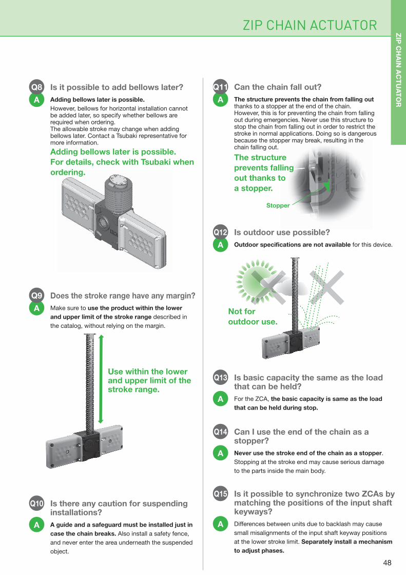
Is it possible to add bellows later?
Adding bellows later is possible.
However, bellows for horizontal installation cannot be added later, so specify whether bellows are required when ordering.The allowable stroke may change when adding bellows later. Contact a Tsubaki representative for more information.
A
Q8
Does the stroke range have any margin?
Make sure to use the product within the lower
and upper limit of the stroke range described in
the catalog, without relying on the margin.
A
Q9
Can the chain fall out?
The structure prevents the chain from falling out thanks to a stopper at the end of the chain. However, this is for preventing the chain from falling out during emergencies. Never use this structure to stop the chain from falling out in order to restrict the stroke in normal applications. Doing so is dangerous because the stopper may break, resulting in the chain falling out.
A
Q11
Is outdoor use possible?
Outdoor specifications are not available for this device.A
Q12
Is there any caution for suspending installations?
A guide and a safeguard must be installed just in
case the chain breaks. Also install a safety fence,
and never enter the area underneath the suspended
object.
A
Q10
Is basic capacity the same as the load that can be held?
For the ZCA, the basic capacity is same as the load
that can be held during stop.
A
Q13
Can I use the end of the chain as a stopper?
Never use the stroke end of the chain as a stopper.
Stopping at the stroke end may cause serious damage
to the parts inside the main body.
A
Q14
Is it possible to synchronize two ZCAs by matching the positions of the input shaft keyways?
Differences between units due to backlash may cause
small misalignments of the input shaft keyway positions
at the lower stroke limit. Separately install a mechanism
to adjust phases.
A
Q15
Use within the lower and upper limit of the stroke range.
Not for
outdoor use.
The structure
prevents falling
out thanks to
a stopper.
Adding bellows later is possible.
For details, check with Tsubaki when
ordering.
Stopper
ZIP CHAIN ACTUATOR ZIP
CH
AIN
AC
TU
AT
OR
48
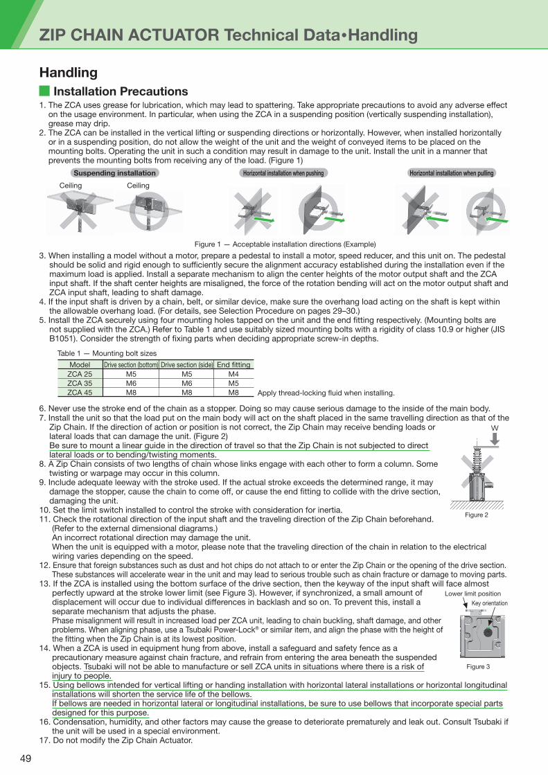
ZIP CHAIN ACTUATOR Technical Data・Handling
6. Never use the stroke end of the chain as a stopper. Doing so may cause serious damage to the inside of the main body.7. Install the unit so that the load put on the main body will act on the shaft placed in the same travelling direction as that of the
Zip Chain. If the direction of action or position is not correct, the Zip Chain may receive bending loads or lateral loads that can damage the unit. (Figure 2)Be sure to mount a linear guide in the direction of travel so that the Zip Chain is not subjected to direct lateral loads or to bending/twisting moments.
8. A Zip Chain consists of two lengths of chain whose links engage with each other to form a column. Some twisting or warpage may occur in this column.
9. Include adequate leeway with the stroke used. If the actual stroke exceeds the determined range, it may damage the stopper, cause the chain to come off, or cause the end fitting to collide with the drive section, damaging the unit.
10. Set the limit switch installed to control the stroke with consideration for inertia.11. Check the rotational direction of the input shaft and the traveling direction of the Zip Chain beforehand.
(Refer to the external dimensional diagrams.)An incorrect rotational direction may damage the unit.When the unit is equipped with a motor, please note that the traveling direction of the chain in relation to the electrical wiring varies depending on the speed.
12. Ensure that foreign substances such as dust and hot chips do not attach to or enter the Zip Chain or the opening of the drive section.These substances will accelerate wear in the unit and may lead to serious trouble such as chain fracture or damage to moving parts.
13. If the ZCA is installed using the bottom surface of the drive section, then the keyway of the input shaft will face almost perfectly upward at the stroke lower limit (see Figure 3). However, if synchronized, a small amount of displacement will occur due to individual differences in backlash and so on. To prevent this, install a separate mechanism that adjusts the phase.Phase misalignment will result in increased load per ZCA unit, leading to chain buckling, shaft damage, and other problems. When aligning phase, use a Tsubaki Power-Lock® or similar item, and align the phase with the height of the fitting when the Zip Chain is at its lowest position.
14. When a ZCA is used in equipment hung from above, install a safeguard and safety fence as a precautionary measure against chain fracture, and refrain from entering the area beneath the suspended objects. Tsubaki will not be able to manufacture or sell ZCA units in situations where there is a risk of injury to people.
15. Using bellows intended for vertical lifting or handing installation with horizontal lateral installations or horizontal longitudinal installations will shorten the service life of the bellows.If bellows are needed in horizontal lateral or longitudinal installations, be sure to use bellows that incorporate special parts designed for this purpose.
16. Condensation, humidity, and other factors may cause the grease to deteriorate prematurely and leak out. Consult Tsubaki if the unit will be used in a special environment.
17. Do not modify the Zip Chain Actuator.
Installation Precautions
Handling
Ceiling Ceiling
Suspending installation Horizontal installation when pushing Horizontal installation when pulling
1. The ZCA uses grease for lubrication, which may lead to spattering. Take appropriate precautions to avoid any adverse effect on the usage environment. In particular, when using the ZCA in a suspending position (vertically suspending installation), grease may drip.
2. The ZCA can be installed in the vertical lifting or suspending directions or horizontally. However, when installed horizontally or in a suspending position, do not allow the weight of the unit and the weight of conveyed items to be placed on the mounting bolts. Operating the unit in such a condition may result in damage to the unit. Install the unit in a manner that prevents the mounting bolts from receiving any of the load. (Figure 1)
3. When installing a model without a motor, prepare a pedestal to install a motor, speed reducer, and this unit on. The pedestal should be solid and rigid enough to sufficiently secure the alignment accuracy established during the installation even if the maximum load is applied. Install a separate mechanism to align the center heights of the motor output shaft and the ZCA input shaft. If the shaft center heights are misaligned, the force of the rotation bending will act on the motor output shaft and ZCA input shaft, leading to shaft damage.
4. If the input shaft is driven by a chain, belt, or similar device, make sure the overhang load acting on the shaft is kept within the allowable overhang load. (For details, see Selection Procedure on pages 29–30.)
5. Install the ZCA securely using four mounting holes tapped on the unit and the end fitting respectively. (Mounting bolts are not supplied with the ZCA.) Refer to Table 1 and use suitably sized mounting bolts with a rigidity of class 10.9 or higher (JIS B1051). Consider the strength of fixing parts when deciding appropriate screw-in depths.
Figure 1 — Acceptable installation directions (Example)
Drive section (bottom)Model Drive section (side) End fitting
M5
M6
M8
M5
M6
M8
M4
M5
M8
ZCA 25
ZCA 35
ZCA 45 Apply thread-locking fluid when installing.
Table 1 — Mounting bolt sizes
Figure 2
W
Figure 3
Lower limit position
Key orientation
49
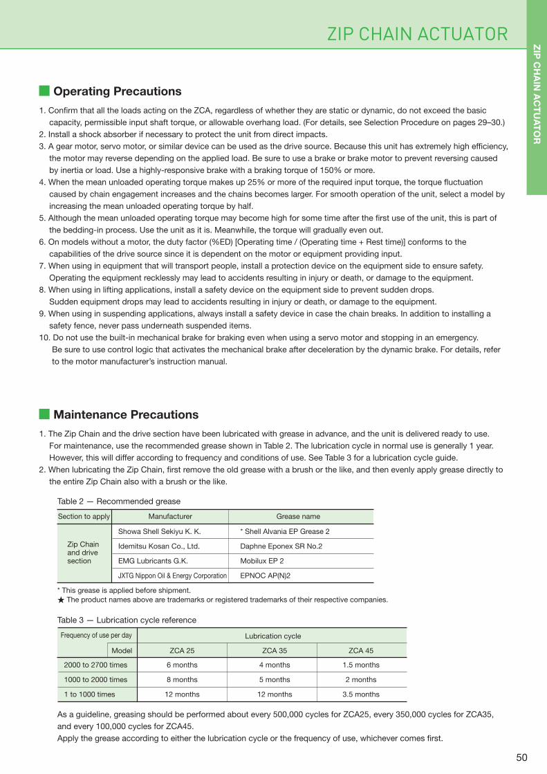
ZIP CHAIN ACTUATOR
Operating Precautions
1. Confirm that all the loads acting on the ZCA, regardless of whether they are static or dynamic, do not exceed the basic
capacity, permissible input shaft torque, or allowable overhang load. (For details, see Selection Procedure on pages 29–30.)
2. Install a shock absorber if necessary to protect the unit from direct impacts.
3. A gear motor, servo motor, or similar device can be used as the drive source. Because this unit has extremely high efficiency,
the motor may reverse depending on the applied load. Be sure to use a brake or brake motor to prevent reversing caused
by inertia or load. Use a highly-responsive brake with a braking torque of 150% or more.
4. When the mean unloaded operating torque makes up 25% or more of the required input torque, the torque fluctuation
caused by chain engagement increases and the chains becomes larger. For smooth operation of the unit, select a model by
increasing the mean unloaded operating torque by half.
5. Although the mean unloaded operating torque may become high for some time after the first use of the unit, this is part of
the bedding-in process. Use the unit as it is. Meanwhile, the torque will gradually even out.
6. On models without a motor, the duty factor (%ED) [Operating time / (Operating time + Rest time)] conforms to the
capabilities of the drive source since it is dependent on the motor or equipment providing input.
7. When using in equipment that will transport people, install a protection device on the equipment side to ensure safety.
Operating the equipment recklessly may lead to accidents resulting in injury or death, or damage to the equipment.
8. When using in lifting applications, install a safety device on the equipment side to prevent sudden drops.
Sudden equipment drops may lead to accidents resulting in injury or death, or damage to the equipment.
9. When using in suspending applications, always install a safety device in case the chain breaks. In addition to installing a
safety fence, never pass underneath suspended items.
10. Do not use the built-in mechanical brake for braking even when using a servo motor and stopping in an emergency.
Be sure to use control logic that activates the mechanical brake after deceleration by the dynamic brake. For details, refer
to the motor manufacturer’s instruction manual.
Maintenance Precautions
1. The Zip Chain and the drive section have been lubricated with grease in advance, and the unit is delivered ready to use.
For maintenance, use the recommended grease shown in Table 2. The lubrication cycle in normal use is generally 1 year.
However, this will differ according to frequency and conditions of use. See Table 3 for a lubrication cycle guide.
2. When lubricating the Zip Chain, first remove the old grease with a brush or the like, and then evenly apply grease directly to
the entire Zip Chain also with a brush or the like.
ManufacturerSection to apply Grease name
Showa Shell Sekiyu K. K.
Idemitsu Kosan Co., Ltd.
EMG Lubricants G.K.
JXTG Nippon Oil & Energy Corporation
* Shell Alvania EP Grease 2
Daphne Eponex SR No.2
Mobilux EP 2
EPNOC AP(N)2
Zip Chain and drive section
As a guideline, greasing should be performed about every 500,000 cycles for ZCA25, every 350,000 cycles for ZCA35,
and every 100,000 cycles for ZCA45.
Apply the grease according to either the lubrication cycle or the frequency of use, whichever comes first.
Table 2 — Recommended grease
Model ZCA 25 ZCA 35
Frequency of use per day Lubrication cycle
6 months
8 months
12 months
4 months
5 months
12 months
ZCA 45
1.5 months
2 months
3.5 months
2000 to 2700 times
1000 to 2000 times
1 to 1000 times
Table 3 — Lubrication cycle reference
* This grease is applied before shipment.
★ The product names above are trademarks or registered trademarks of their respective companies.
ZIP
CH
AIN
AC
TU
AT
OR
50

ZIP CHAIN ACTUATOR
Global Series
Examples of Special Support for Motors
The Global Series is a motor that complies with international directives, standards, and systems.
Tsubaki provides motors that comply with CE standards for Europe, UL standards for North America, and CCC standards for China.
We also offer the TRIPLE200, which complies with all three standards—CE, UL, and CCC—in a single motor.
▶CE complianceProducts destined for the European market cannot be
exported unless they are marked with a CE mark proving
that they comply with the safety requirements defined by
the European CE directive.
A product is considered CE-compliant if it has the CE mark
affixed to the product itself as proof of compliance with the
CE directive.
▶Declaration of Conformity
Tsubaki has prepared the necessary self-conformance
declarations for CE compliance.
Applicable directive: Low Voltage Directive 2014/35/EU
Applicable standard: EN60034-1 (motor-related standard)
▶UL compliance
UL is the abbreviation for “Underwriters Laboratories Inc.”
and represents the safety testing standard used in the
United States.
A product is considered UL-compliant if it has the UL mark
affixed to the product itself as proof of compliance through
the use of a UL-compliant motor. A product marked with
the C-UR mark indicates compliance with both UL and
CSA standards.
▶UL specifications
Applicable standard: UL1004
UL File No:E225995
▶CCC compliance
The CCC mark is a compulsory certification system used in
China. Any small-power motors of 1.1 kW or less being
exported to China must display a CCC mark to indicate
compulsory certification.
▶CCC mark licensing
The CCC mark indicates that certification has been
obtained from the China Quality Certification Center (CQC).
National standard: GB12350
CEEU countries
ULUnited States, Canada
CCCChina
51

Technical Sheet
Inquiry Sheet
ZIP CHAIN ACTUATOR 53
52
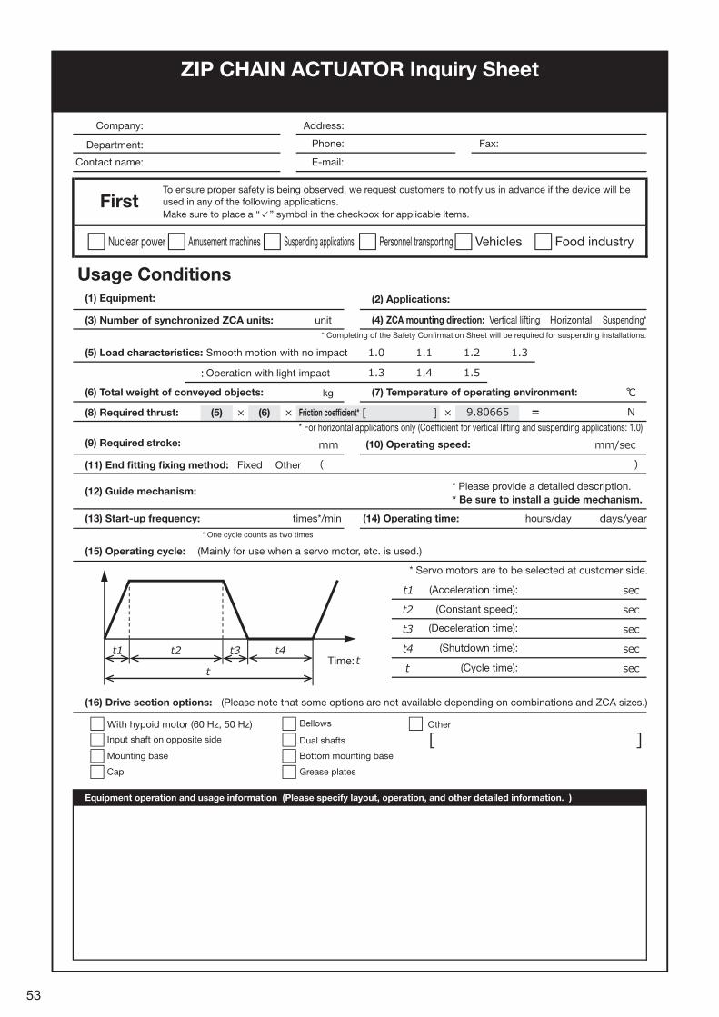
ZIP CHAIN ACTUATOR Inquiry Sheet
* Servo motors are to be selected at customer side.
Input shaft on opposite side
Bellows
Dual shafts
Bottom mounting base
Grease plates
Other
Mounting base
Cap
Equipment operation and usage information (Please specify layout, operation, and other detailed information. )
* One cycle counts as two times
days/year
* Completing of the Safety Confirmation Sheet will be required for suspending installations.
Time:
Nuclear power Amusement machines Suspending applications Personnel transporting Vehicles Food industry
kg
With hypoid motor (60 Hz, 50 Hz)
Company:
(1) Equipment:
unit
Address:
Phone:
E-mail:
Fax:
Contact name:
To ensure proper safety is being observed, we request customers to notify us in advance if the device will be
used in any of the following applications.
Make sure to place a “ ” symbol in the checkbox for applicable items.
Department:
Usage Conditions
(2) Applications:
(4) ZCA mounting direction:(3) Number of synchronized ZCA units:
(5) Load characteristics: Smooth motion with no impact
Operation with light impact
Vertical lifting Horizontal Suspending*
(6) Total weight of conveyed objects:
(8) Required thrust: (6)(5)
(9) Required stroke:
Fixed Other
(10) Operating speed:
Friction coefficient*
* For horizontal applications only (Coefficient for vertical lifting and suspending applications: 1.0)
(7) Temperature of operating environment:
(11) End fitting fixing method:
(12) Guide mechanism:
(13) Start-up frequency:
(15) Operating cycle:
(16) Drive section options: (Please note that some options are not available depending on combinations and ZCA sizes.)
(Mainly for use when a servo motor, etc. is used.)
(14) Operating time: hours/daytimes*/min
* Please provide a detailed description.
* Be sure to install a guide mechanism.
(Acceleration time):
(Constant speed):
(Deceleration time):
(Shutdown time):
(Cycle time):
53
First

The device details described in this catalog are intended primarily for model selection. Before using
the device, read the instruction manual thoroughly, and ensure the device is used correctly.
●Do not release the brake when a load is acting on the unit under any circumstances. If the brake is released while a load is acting on the unit, the supported object may fall or the moving sections may suddenly start to move.●Do not use the unit in an explosive atmosphere. Doing so may cause the unit to become flammable, explode or catch fire, or result in
personal injury.●When using in equipment that will transport people, install a protection device on the equipment side to ensure safety. Operating the
equipment recklessly may lead to accidents resulting in injury or death, or damage to the equipment.●When using in lifting applications, install a safety device on the equipment side to prevent sudden drops. Sudden equipment drops may
lead to accidents resulting in injury or death, or damage to the equipment.●When using the unit in equipment hung from above, install safety fence to prevent entering the area beneath any suspended objects.
A safeguard must also be installed just in case the chain breaks.●Keep hands and any other part of the body, clothes or accessories away from any movable parts. Otherwise, they may be entangled or
trapped in movable parts, resulting in personal injury or death and/or damage to the equipment.●If a terminal box is used, do not operate the unit with the terminal box cover removed. Doing so may result in electrical shock.
Be sure to replace the cover after performing any work on the terminal box.●When operating manually from a manual operation shaft, be sure to operate according to the instruction manual and with no load applied.●Observe the general standards stipulated in Part 2, Chapter 1, Section 1 of the Ordinance on Industrial Safety and Health.●For attachment/removal from equipment, transportation, installation, wiring, operation, maintenance and inspection of the unit: • Always work by following the instructions in the instruction manual. • Work must be performed by those who have specialized knowledge and skills. Otherwise explosion, ignition, fire, electrical shock,
injury or damage to the equipment may result.• During electrical wiring, always observe the precautions listed in the instruction manual as well as the regulations in the electrical equipment
standards and indoor wiring regulations. Grounding in particular is important for preventing electrocution, so always ensure that the product is reliably grounded.
• Turn off the source power supply in advance and ensure that the switch cannot be unintentionally turned on. In the event of power stoppage, take the same action.
• Wear clothing suited to the work, and wear appropriate protective gear (safety goggles, gloves, safety footwear, or other necessary safety equipment).
●Do not attempt to modify the unit.
●Do not use the unit outside of the specified ranges listed on the nameplate and external diagrams, and in the catalog. Doing so may result in injury and/or damage to the unit.●Use the unit within the appropriate power supply voltage range. There is a risk of burning out the motor and of fire when using the unit outside this range.●Make sure the limit switch wiring and stroke adjustment position are correct before energizing the unit.●Check the rotational direction before incorporating the unit into any other equipment. Mounting the unit against the correct rotational direction may result in personal injury and/or damage to the unit. ●Do not insert your fingers or objects into any opening on the unit. Doing so may result in injury and/or damage to the unit.●Functionality and performance may decrease because of part wear and the lifespan of parts. Perform periodic inspections according to the instruction manual. If the unit shows degraded functionality and performance or is damaged, immediately stop operation and contact your local supplier. Not doing so may result in electrical shock, injury or fire.●During operation, the unit, motor, or speed reducer may heat up to a high temperature. Keep hands and other body parts from coming into contact with these devices. Failure to do so may result in burn injuries.●Do not operate the unit with an applied load that is higher than the rated load. Doing so may result in injury and/or damage to the unit.●Do not remove the nameplate.●Customer alterations of the unit are outside the scope of the Tsubaki warranty. Therefore, Tsubaki assumes no responsibility for such alterations.●Before using the device, thoroughly read the instruction manual provided with the unit, and ensure the unit is used correctly. If no instruction manual
is available, use the device name and model to request an instruction manual from the distributor where the device was purchased, or from the Tsubaki sales office.
●Be sure to give the instruction manual to the end user.
1.LIMITED WARRANTYProducts are covered by the Tsubaki warranty for up to 18 months from shipment from the factory or 12 months after the start of use (starting from the incorporation of the product into the customer’s equipment), whichever is shortest. However, the warranty period may vary, depending on the usage conditions.
2. SCOPE OF WARRANTYDuring the limited warranty period, a failure in a product installed, used, and maintained according to the catalog, instruction manual, or other appropriate documents, can be returned to Tsubaki for replacement or repair free of charge.However, please note that the limited warranty covers only Tsubaki products. The following expenses will not be covered by the warranty. (Instruction manuals and other appropriate documents include any documents specially submitted to the customer.)
(1) Expenses required for removal/installation of the product from/to the customer’s equipment, or for replacement or repair, or for related construction costs.
(2) Costs required to transport the customer’s equipment to a repair shop.
(3) Lost profits or other extended damages due to breakdown or repair.
3. REPAIR SERVICESTsubaki will accept and repair products that have failed due to the following items—regardless of whether the warranty period is in effect—for a fee.
(1) The product was not installed correctly according to the
instruction manual. (2) The product was not sufficiently maintained or was handled
incorrectly. (3) The product failed due to a failure between the product and a
separate device. (4) The product structure was changed in any way, such as
through modification. (5) The product was repaired by someone other than Tsubaki or a
Tsubaki-designated factory. (6) The product was used outside the correct operating
environment as stated in the instruction manual. (7) The product failed due to a force majeure such as a natural
disaster or illegal actions by a third party. (8) The product failed due to a secondary failure resulting from a
defect in a customer’s device. (9) The product failed due to parts installed at the request of the
customer or due to parts used per the customer’s specifications.
(10) The product failed due to a wiring failure or parameter setting error caused by the customer.
(11) The product failed as a result of reaching its normal service life according to the conditions of use.
(12) The product failed due to any damage for which Tsubaki is not responsible.
4. DISPATCHING OF TSUBAKI ENGINEERSService expenses such as those incurred when dispatching engineers to perform an investigation, adjustment, or trial operation of a Tsubaki product will be charged separately.
Warranty
For Safe Use of the ZIP CHAIN ACTUATOR
WARNING Observe the items below to prevent danger.
CAUTION Observe the items below to prevent accidents.
The device details described in this catalog are intended primarily for model selection. Before using the device, read the instruction manual thoroughly, and ensure the device is used correctly.CAUTION
Japan Headquarters +81 6-6441-0011 https://tsubakimoto.com
United States of America U.S. Tsubaki Power Transmission, LLC +1 847-459-9500 https://www.ustsubaki.com/
Brazil Tsubaki Brasil Equipamentos Industriais Ltda. +55 11-3253-5656 http://tsubaki.ind.br/
Canada Tsubaki of Canada Limited +1 905-676-0400 http://tsubaki.ca/
Global Group Companies
AMERICAS
Netherlands Tsubakimoto Europe B.V. +31 78-6204000 https://tsubaki.eu/
France Kabelschlepp France S.A.R.L. +33 1-34846365 https://kabelschlepp.fr/
Germany Tsubaki Deutschland GmbH +49 89 2000 133 80 http://tsubaki.de/
Tsubaki Kabelschlepp GmbH +49 2762-4003-0 https://tsubaki-kabelschlepp.com/
Italy Kabelschlepp Italia S.R.L. +39 0331-350962 https://kabelschlepp.it/
Russia ○○○ Tsubaki Kabelschlepp +7 499-4180212 http://kabelschlepp.ru/
Spain Tsubaki Ibérica Power Transmission S.L. +34 911-873450 http://tsubaki.es/
United Kingdom Tsubakimoto U.K. Ltd. +44 1623-688-700 https://tsubaki.eu/
EUROPE
Singapore Tsubakimoto Singapore Pte. Ltd. +65 6861-0422/3/4 http://tsubaki.sg/
Australia Tsubaki Australia Pty. Limited +61 2-9704-2500 http://tsubaki.com.au/
India Tsubaki India Power Transmission Private Limited +91 44-7101-2000 http://tsubaki.in/
Indonesia PT. Tsubaki Indonesia Trading +62 21-8945-8898 http://tsubakimoto.co.id/
Malaysia Tsubaki Power Transmission (Malaysia) Sdn. Bhd. +60 3-5888-8275 http://tsubaki.my/
New Zealand Tsubaki Australia Pty. Limited - New Zealand Branch +64 9 352-2085 http://tsubaki.com.au/
Philippines Tsubakimoto Philippines Corporation +63 2-808-0067 http://tsubaki.ph/
Thailand Tsubakimoto (Thailand) Co., Ltd. +66 2-262-0667/8/9 http://tsubaki.co.th/
Vietnam Tsubakimoto Vietnam Co., Ltd. +84 24-6274-1449 http://tsubaki.net.vn/
INDIAN OCEAN RIM
Korea Tsubakimoto Korea Co., Ltd. +82 2-2183-0311 http://tsubakimoto-tck.co.kr/
Taiwan Taiwan Tsubakimoto Co. +886 3-3293827 https://tsubakimoto.com.tw/
EAST ASIA
China Tsubakimoto Chain (Shanghai) Co., Ltd. +86 215396-6651/2 http://tsubaki-sh.cn/
CHINA
Note: In accordance with the policy of TSUBAKIMOTO CHAIN CO. to constantly improve its products, the specifications in this catalog are subject to change without notice.
Catalog No. 985K559-1 ©2020/4 TSUBAKIMOTO CHAIN CO.
The Tsubaki Eco Link logo is used only on products
that satisfy the standards for environmental friendliness set by the Tsubaki Group.
The logos, brand names, or product names in
this catalog are trademarks or registered
trademarks of Tsubakimoto Chain Co. and/or
its subsidiaries and/or affiliates in Japan
and/or other countries.