tt503a – dispositivos fotônicos aula 5 - fontes Ópticas.gallep/tt708/a5.pdf · • light...
TRANSCRIPT

1
tt503A – Dispositivos Fotônicos Aula 5 - fontes Ópticas.

2
Sources for Optical Transmitters
• Many types of optical sources are available – Light Emitting Diodes (LEDs) – Solid state lasers – Gas lasers – Semiconductor lasers – Fiber lasers
• Semiconductor Lasers are preferred – Powered by electrical energy – Directly converts electrical signals to optical signals
Copyright VPIsystems. All rights reserved. 2
3
Semiconductor Laser Features • High modulation bandwidth (> 10 Gbit/s) • Small size
– Packaged: ~ 2×1×1 cm – Unpackaged: ~ grain of salt, 0.5mm × 200µm × 100µm
• Intense single spatial mode • Energy efficient • Narrow spectral linewidth • Can be single longitudinal mode (monochromatic) • Reliable operation • Can be integrated
Copyright VPIsystems. All rights reserved. 3

What does LASER stand for?
LASER is an acronym for:
LIGHT
AMPLIFICATION by
STIMULATED
EMISSION of
RADIATION
• How does it work? • Why amplification? • What is stimulated emission? Copyright VPIsystems. All rights reserved. 4

How does a Laser work?
A functional view of a laser: 4 main parts
3) Optical Resonator (Cavity)
Mirrors Mirrors 2) Energy Pump (Current Source)
Mirror Loss
Mirror Loss
4) Losses: 1) Active (Gain) Medium
Material and Waveguide
Copyright VPIsystems. All rights reserved. 5
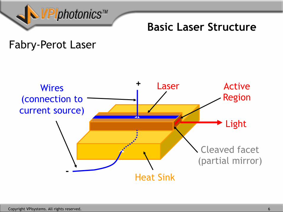
Basic Laser Structure
Fabry-Perot Laser
Light
Cleaved facet (partial mirror)
Active Region
Heat Sink
Laser
-
Wires (connection to current source)
+
Copyright VPIsystems. All rights reserved. 6

A Basic Laser Structure
Fabry-Perot Laser (longitudinal section)
+
-
Energy Pump (Current Source)
Active region (provides gain)
Cleaved facet (partial mirror)
P-layer
N-layer
Cleaved facet (partial mirror)
PN Junction
photons
Holes
Electrons
Copyright VPIsystems. All rights reserved. 7

Optical Emission Processes
Light produced by spontaneous emission:
Excited state
Ground state
E2
E1
– Random propagation direction – Random phase – Random frequency – is incoherent (broad linewidth)
Copyright VPIsystems. All rights reserved. 8

Optical Emission Processes
• Stimulated Emission
Excited state
Ground state E1
E2
• A photon with energy > (E2 – E1): triggers transition of an excited electron
photon
à identical photon is emitted
Identical photon
• Produced light is coherent (desirable)
Copyright VPIsystems. All rights reserved. 9
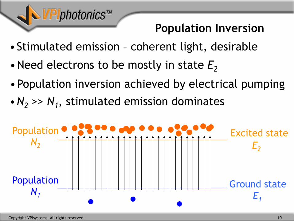
Population Inversion
• Stimulated emission – coherent light, desirable
• Need electrons to be mostly in state E2
• Population inversion achieved by electrical pumping
Population N2
Population N1
Excited state
Ground state E1
E2
• N2 >> N1, stimulated emission dominates
Copyright VPIsystems. All rights reserved. 10

Optical Cavity and Feedback
• Light amplification by stimulated emission… is not strong, especially if the active region is short
• Optical cavity provides feedback into active region
• Light is reflected repeatedly and greatly amplified
Excited state
Ground state E1
E2
along the laser
N2
N1
Copyright VPIsystems. All rights reserved. 11

Optical Losses and Laser Output
• One mirror is partially transmitting, to get output
• Photons transmitted out are lost (mirror loss)
• Other losses: scattering in the material, nonradiative processes
Excited state
Ground state E1
E2
along the laser
N2
N1
Copyright VPIsystems. All rights reserved. 12
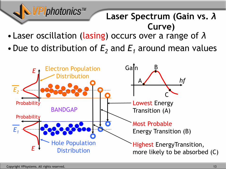
Laser Spectrum (Gain vs. λ Curve)
• Laser oscillation (lasing) occurs over a range of λ • Due to distribution of E2 and E1 around mean values
BANDGAP
Gain
hf
E1
E2
Electron Population Distribution
E
Probability
Hole Population Distribution E
Probability
A
B
C Lowest Energy Transition (A)
Most Probable Energy Transition (B)
Highest EnergyTransition, more likely to be absorbed (C)
Copyright VPIsystems. All rights reserved. 13

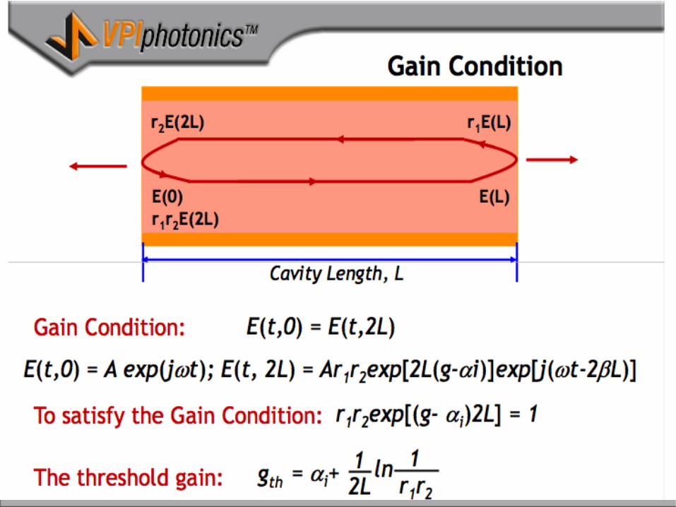
Lasing Conditions For lasing to initiate in a cavity, two conditions need to be satisfied:
– Gain condition: The electric field of the light, after completing one round trip inside the cavity, should have the same amplitude
– Phase condition: The electric field of the light, after completing one round trip inside the cavity, should have the same phase
one round trip
Copyright VPIsystems. All rights reserved. 14

Copyright VPIsystems. All rights reserved. 16

Phase Condition
Discrete modes that can be supported by the cavity are called longitudinal modes
P
Copyright VPIsystems. All rights reserved. 17
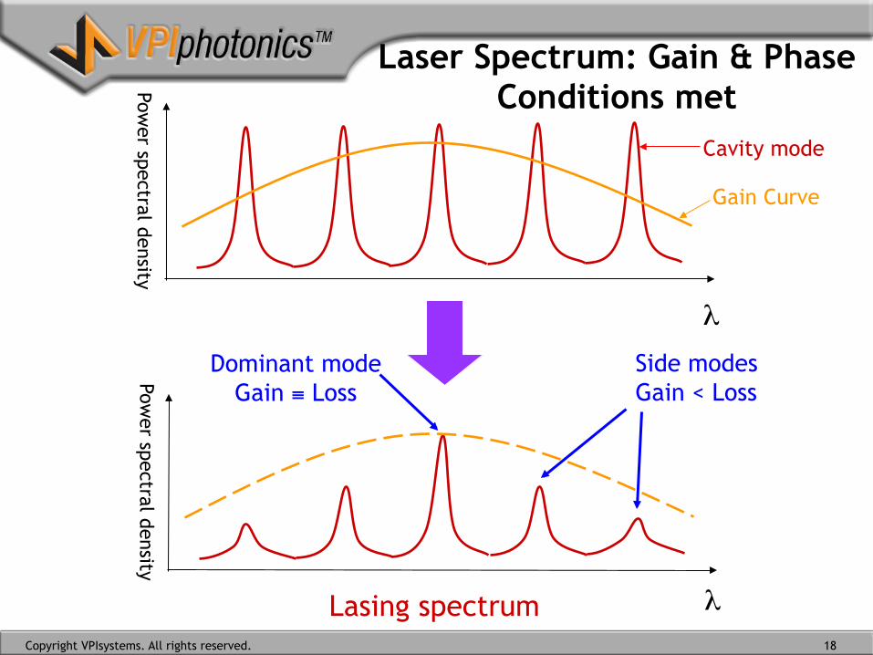
Laser Spectrum: Gain & Phase Conditions met Pow
er spectral density Pow
er spectral density
Cavity mode
Gain Curve
Dominant mode Gain ≡ Loss
Side modes Gain < Loss
Lasing spectrum
λ
λCopyright VPIsystems. All rights reserved. 18
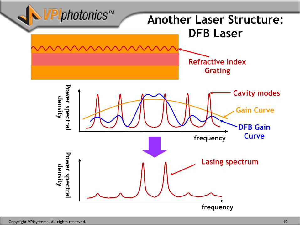
Another Laser Structure: DFB Laser
frequency
frequency
Lasing spectrum
Cavity modes
Gain Curve
DFB Gain Curve
Power spectral density
Power spectral density
Refractive Index Grating
Copyright VPIsystems. All rights reserved. 19

Another Laser Structure: DFB Laser
λ / 4
frequency
frequency
Power spectral density
Power spectral density
Lasing spectrum
Cavity modes
Gain Curve
1/4-wave shifted DFB Gain Curve
1/4-wave shifted Grating
Copyright VPIsystems. All rights reserved. 20

Rate Equation Rate equation describe the dynamic interaction between excited electrons and photons
Change in carrier density:
Change in photon density:
Contribute from Current
Decay of electrons
Usage of electron by
Stimulated emission
Photon generated by stimulated emission
Decay of photon
Photon generated by Spontaneous emission
Copyright VPIsystems. All rights reserved. 21

Light-Current Characteristics
• The L-I curve: output light power vs. input current • Diode characteristics, threshold current Ith
• For I > Ith, light power increases linearly with I
current
Light output (power)
Ith
Spontaneous emission region
Stimulated emission region
Copyright VPIsystems. All rights reserved. 22

Direct-Current Modulation
The information is encoded on semiconductor lasers by current modulation
current
Light output (power)
Ith
Modulated Laser Light
Current modulation
Copyright VPIsystems. All rights reserved. 23
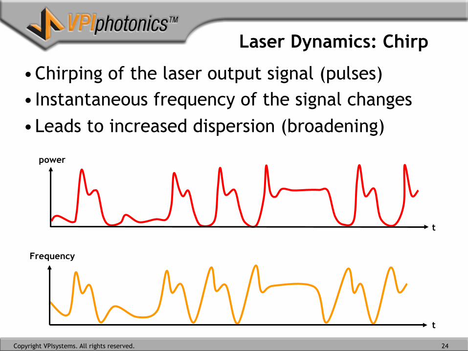
Laser Dynamics: Chirp
• Chirping of the laser output signal (pulses) • Instantaneous frequency of the signal changes • Leads to increased dispersion (broadening)
t
t
Frequency
power
Copyright VPIsystems. All rights reserved. 24

Laser Dynamics: Modulation Bandwidth
A
B
100MHz 10GHz 2GHz 500MHz
+10
0
-10
-20
A B
current
Light output (power)
• Determines maximum direct modulation speed • Increases with increasing drive (bias) current • Within practical limits, get multi-GHz modulation
Copyright VPIsystems. All rights reserved. 25

Laser Dynamics: Turn On Delay
Delay between injection of current and generation of light
t
t
t
Current
Carrier density
Light output (power)
Turn on delay
B
C
D
E
A
FH
G
Copyright VPIsystems. All rights reserved. 26

Laser Dynamics: Relative Intensity Noise
Copyright VPIsystems. All rights reserved.
Current
Light output (power)
1
2
3
Frequency
RIN
1 2 3
Frequency shape of RIN depends on laser driving conditions
27

28

29
0.4 0.5 0.6 0.7 0.8 0.9 1.0 1.1 1.2 1.3 1.4 1.5 1.6
Blue
Gre
enO
rang
eY
ello
w
Red
λ
1.7Infrared
Vio
let
GaA
s
GaA
s 0.55
P 0.45
GaAs1-yPy
InP In0.
14G
a 0.86
As
In1-xGaxAs1-yPyAlxGa1-xAs
x = 0.43
GaP
(N)
GaS
b
Indirectbandgap
InG
aNSi
C(A
l)
In0.
7Ga 0.
3As 0.
66P 0.
34
In0.
57G
a 0.43
As 0.
95P 0.
05
Free space wavelength coverage by different LED materials from the visible spectrum to theinfrared including wavelengths used in optical communications. Hatched region and dashedlines are indirect Eg materials.
In0.49AlxGa0.51-xP
© 1999 S.O. Kasap, Optoelectronics (Prentice Hall)

30

31
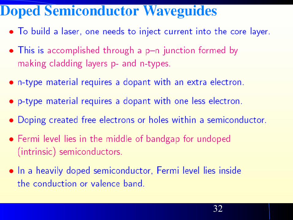
32
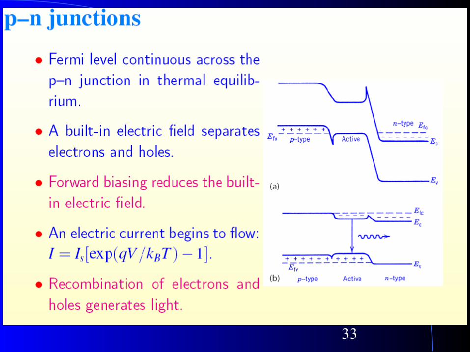
33
34
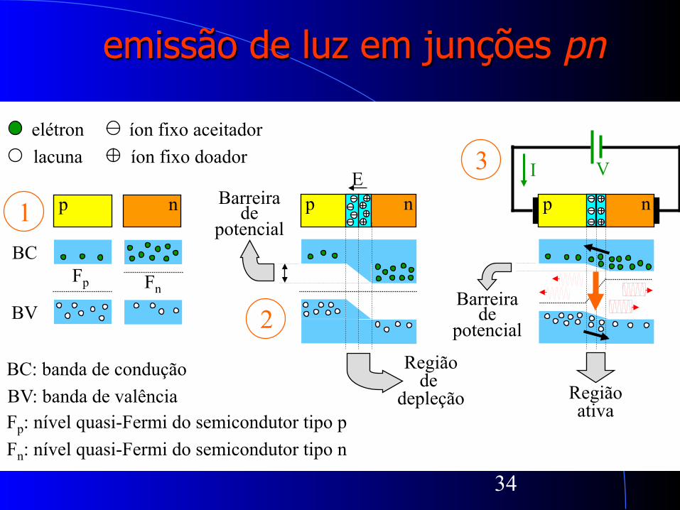
p n
BC
BV
Fp Fn
p n E
Barreira de
potencial
Região de
depleção
elétron lacuna
íon fixo aceitador íon fixo doador
BC: banda de condução BV: banda de valência Fp: nível quasi-Fermi do semicondutor tipo p Fn: nível quasi-Fermi do semicondutor tipo n
1
2
3 p n
Barreira de
potencial
V I
Região ativa
emissão de luz em junções pn
35
Dispositivos semicondutores ópticos LED vs. laser
l Diodo emissor de luz (LED): luz incoerente, largura espectral entre 30 e 60 nm, grande espalhamento de luz, potência de saída < 10 mW para correntes > 100 mA e estável com a temperatura, modulação até centenas de MHz
l Laser : luz coerente, multimodo e monomodo, largura espectral + estreita, modulação máxima de centenas GHz, pequeno espalhamento de luz, potência de saída pode chegar a dezenas de mW para correntes inferiores a 50 mA, porém dependente da temperatura

36
metalização
região ativacontatometálico
contatode ouro
contatometálico
fibra óptica
resina
n-GaAs
LED de Emissão superfcial (SLED)

37
LED Emissão lateral (ELED)
p-AlGaAs
região ativa (AlGaAs)
n-AlGaAs
p+-AlGaAs
n-GaAs
eletrodo
eletrodo n+-GaAs

38
Laser - Características gerais l Amplamente utilizado em sistemas de comunicação
óptica l Estrutura capaz de amplificar a luz no interior de uma
cavidade refletiva, levado-a a oscilação através de realimentação positiva
l A potência óptica suficiente para permitir transmissões, sem repetidores ou amplificadores ópticos, a distâncias, em média, entre 100 e 150 km
l Modulação da intensidade luz através da modulação de sua corrente em até dezenas de GHz → com a utilização de técnicas coerentes, a modulação da fase e da freqüência do laser é possível
l A freqüência de operação do laser varia com a corrente e a temperatura → possibilidade de sintonia

39
Laser FP Corrente de limiar e a temperatura
Corrente (mA)
Potência óptica (mW
)
40
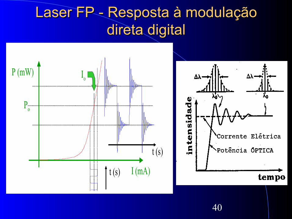
Laser FP - Resposta à modulação direta digital
P (mW)
I (mA)
Po
t (s)
t (s)
Io
41
42

43

44
45
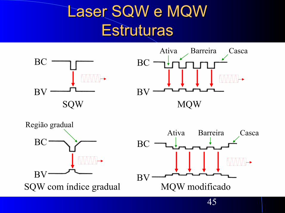
Laser SQW e MQW Estruturas
BC
BV
BC
BV
SQW
SQW com índice gradual
Região gradual
MQW
MQW modificado
BC
BV
BC
BV
Barreira Ativa Casca
Barreira Ativa Casca
46
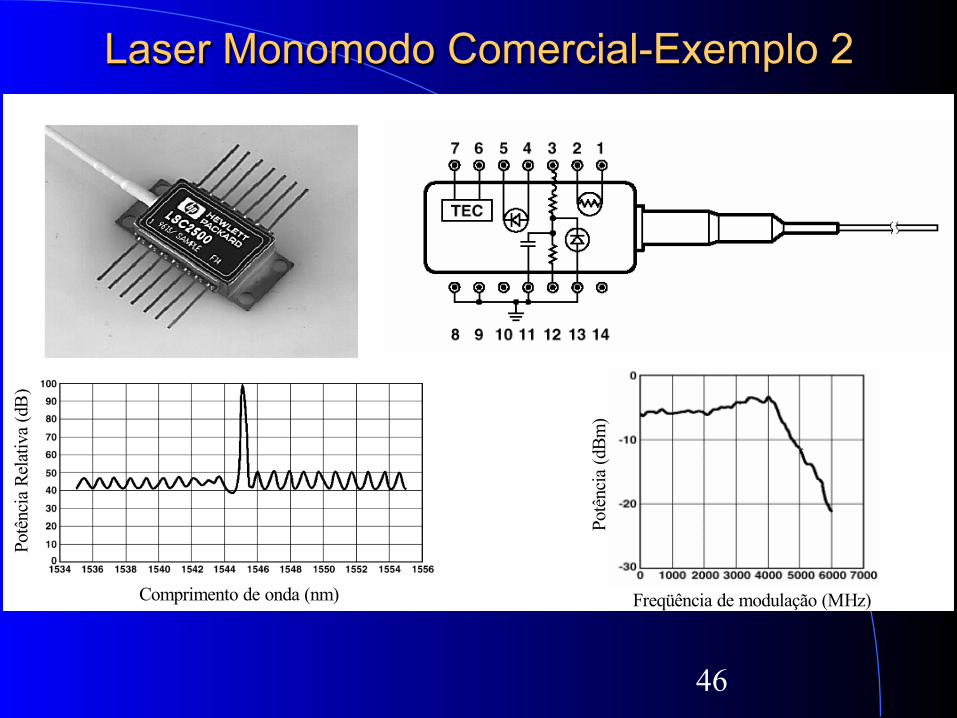
Laser Monomodo Comercial-Exemplo 2
Po
tênc
ia (d
Bm)
Freqüência de modulação (MHz)
Potê
ncia
Rel
ativ
a (d
B)
Comprimento de onda (nm)

47

48
Modulação direta do laser Exemplo de circuito
Sinal de modulação
Opcional para DC
IDC
VPOL
VREF
Fotodetector para monitoração Laser

49

50
Exercícios
Dado:
Assuma:

51
Dado:
Assuma:
Dado: