ttechnical echnical overview
TRANSCRIPT

Technical OverviewEVAPOTRANSPIRATION SYSTEMS
Technical Overview

2
Project Staff
Edward Winant – Author
Jennifer Hause – Technical Review
Andrew Lake – Technical Review
Tim Suhrer – Editorial Review
John Fekete – Senior Graphics Designer
Jeanne Allen – Project Coordinator
West Virginia University
Morgantown, WV 26506-6064
(304) 293-4191
www.nesc.wvu.edu
The contents of this publication are provided for information pur-poses and do not necessar ily reflect the views and policies of the U.S. Environmental Protection Agency, nor does the mention of trade names or commercial products constitute endorsement or recommendation for use.
REPRINTS
Permission to quote from or reproduce this pub lication is granted when due acknowledgement is given.
TECHNICAL OVERVIEW EVAPOTRANSPIRATION SYSTEMS

3
INTRODUCTIONEvapotranspiration systems (ET) and evapotranspiration absorbtion systems
(ETA) are an upcoming and novel solution to some difficult onsite wastewater treatment needs. Using the sun and plants to uptake water, as well as soil for ETA systems as par t of an onsite wastewater system provides both wastewater treatment and ultimate dispersal of the water. This makes ET/ETA systems environmentally sound practices that can also be very cost-effective.
The drawback to ET/ETA systems is that they can not be used everywhere, relying as they do on sufficient sunlight. There are many sites that lack ade quate levels of evaporation or have too much rainfall, or are situated on slopes facing the wrong way. To adequately treat and uptake wastewater, the site should have an evaporation rate that exceeds the natural precipitation rate.
DESIGN: General There are many different configurations for soil absorption systems. They
include trenches, beds, pressure trenches, low-pressure pipes, serial trenches, and contour trenches. In all these configurations, the goal is to spread the efflu-ent out as widely as possible to let it soak into the g round. Soil treatment is designed to remove contaminants and disperse the effluent into the soil.
The design goal with ET systems is to promote uptak e of effluent through plants and sunlight to disperse the water without using the soil. ETA systems are hybrid systems, where some soil treatment and dispersal is used b ut assist-ed by evapotranspiration activity.
Keys to enhancing the uptake of effluent by evapotranspiration are maximiz-ing sunlight, wind sweep, and healthy vegetation, while trying to avoid excessive rainfall or humidity. Additionally, the trenches are constructed with sand or pea gravel above the pipes to enhance wicking the effluent toward the surface.
r
Figure 1: Cross Section of a Typical Evapotranspiration BedAdopted from: Frank (1996), copyright © Water Environmental Federation, used with permission

4
DESIGN: Evapotranspiration SystemsET systems make complete use of uptake through vegetation and evapora-
tion. ET rates are typically slower than soil infiltration rates, so ET systems will generally be larger than conventional drainfields. Some states regulate that the trench bottoms be lined to prevent infiltration.
The ET trenches will include sand or pea g ravel below the distribution pipe and above it. This material should be brought to within a few inches of the exist ing ground. As mentioned above, this is to assist in wicking the effluent to the surface for plant uptake. Final backfill should be sandy or loamy soil to enhance water uptake.
Sizing the system is done with a simple w ater balance. Water into the sys tem is the effluent from the house plus an y rainfall. Typical designs include berms or other diversions for runoff, so the rainfall calculation is whatever falls directly on the system. Water out of the system is measured by the pan evapo ration rate for that area. As long as the water out meets or exceeds the water in, the ET system should work properly.
Estimating the rainfall amount can be a tr icky proposition. A year of relative drought may be followed by the worst rainy season in memory. Further, season al differences can be impor tant. Wet springs may stress a system that works fine in late summer, or frigid winter temperatures can reduce transpiration rates to a bare minimum.
Figure 2: Diagram of an ET System

5
Accounting for these variations can use a number of methods. Preparing designs for winter and summer use can be done b y getting ET rates for both seasons. If these rates are relatively close, a composite yearly rate can be used. In regions with significant rainy seasons, system sizing should be based on the rates for the rainy season. As for calculating yearly precipitation, the design should account for the historical precipitation record. Some states call for sizing based on the wettest year in the past 10- or 20-year period. Others may base design on the 50- or 100-year prediction.
Two additional design features may be incorporated into ET systems to improve their long-term functioning. Pressure distribution, instead of gravity, will disperse the effluent more evenly through the system and reduce over-satura-tion and ponding. Alternative fields, that is, two fields where one is used while the second rests, allow for recovery of saturated trenches.
DESIGN: Evapotranspiration Absorbtion SystemsETA systems make use of soil infiltration as well as evapotranspiration activi ty.
Thus, they will tend to be smaller than ET systems and potentially smaller than conventional drainfields as well. The drawback is that the soils on the site must be acceptable for use in effluent treatment and dispersal. ETA systems use the same water balance as ET systems, except that they also include water out through soil infiltration.
These trenches are constructed as normal drainfield trenches, except that the covering backfill material should be sandy loam soil, and sand wic ks are incorporated above the distribution pipes.
Again, the system should be graded and have berms to prevent surface runoff from saturating the system. Pressure distribution and alternating fields, if incorporated in the design, will add to the system lif e.
Figure 3: Schematic of an ETA Mound SystemSource: adapted from Converse and Tyler, copyright © 1987 by the American Society of Agricultural Engineers, reprinted with permission
SEPTIC TANK DOSING CHAMBER
ETA MOUND
6
SITING ADVANTAGES AND DISADVANTAGESThese systems are designed to overcome two soil limitations: rapidly drain-
ing soils and impermeable soils. ET systems with liners work well to address the rapidly draining soil condition, where a conventional drainfield would be a hazard to groundwater contamination. ET or ETA systems address imperme able or slowly permeable soils by reducing the hydraulic load on the soil.
The disadvantage to these systems is climatic. They will work properly only when the evapotranspiration rate exceeds the rainfall and the applied waste-water loads. In the case of ETA systems, the soil will provide additional capacity to receive water. However, the balance of evaporation over rain and effluent must be maintained year-round, or accumulations in the rainy or cold seasons will flood the system.
Thus, near-tropical areas that are warm but very rainy might not be suitable locations. Also, temperate zones with warm, dry summers but cold and snowy winters would not be good candidates for ET/ETA systems.
OPERATION AND MAINTENANCEO&M for ET/ETA systems is very similar to conventional septic system prac-
tice. Mostly, this involves pumping out the septic tank on a regular basis and checking to make sure the structure and all the fittings are sound and w orking properly.
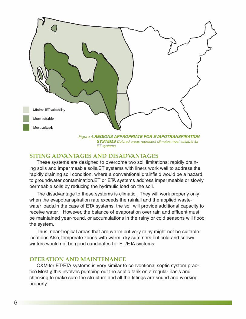
Figure 4: REGIONS APPROPRIATE FOR EVAPOTRANSPIRATION SYSTEMS Colored areas represent climates most suitable for ET systems.

7
Additionally, the vegetation on the system should be kept mowed or pruned. Any surrounding trees should be kept back to allow wind sweep and sunlight to reach the fields.
COSTSThe major cost in constructing an ET/ETA system is usually labor. Costs will
vary by geographic region, size of the system, and choice of mater ials, but in general, a typical single-family ET/ETA system would cost in the neighbor hood of $3-4,500. This would include a day or two of labor and backhoe opera tion, around 300 feet of 4-inch PVC pipe, 40 tons of gravel, 40 tons of sand, and all the plumbing connections. A bed system would be slightly more expensive, as there is more excavation required and more gravel to lay in the bed than in trenches. A typical bed would cost around $5,000. To complete the system, a septic tank could be installed at a typical cost of $500 to $1000, or an aerobic tank for around $2000.
Pressure systems would be slightly more expensive. There are some sav ings in using less pipe and smaller trenches , but the pump or siphon chamber adds to the costs. These systems, including the septic tank, usually cost $5-
6,000. Alternating fields would also add to the cost, with the addition of the second drainfield. An alternating field system would probably run around$5,500-6,000.
REFERENCESColdham, B., “Beyond the Basic Septic System: Practical Alternatives.”Journal of Light
Construction, November 1988.
Rural Systems Engineering Onsite Wastewater Disposal: Evapotranspiration and
Evapotranspiration/Absorption Systems 1983