tteecchhnniiccaall s suummmmaarryy -...
TRANSCRIPT

AA HHIIGGHH RREESSOOLLUUTTIIOONN SSTTEERREEOOSSCCOOPPIICC CCOOMMPPUUTTEERR PPRROOJJEECCTTIIOONN
DDIISSPPLLAAYY FFOORR SSUURRGGIICCAALL PPLLAANNNNIINNGG
Kevin Montgomery PhD, Frederic Mazzella,
Michael Stephanides MD, Stephen Schendel MD DDS
National Biocomputation Center
Stanford University
701A Welch Road, Suite 1128
Stanford, CA 94305
650.498.6978 (voice), 650.498.5626 (fax)
Keywords: projection display, virtual reality, virtual surgery, surgical planning, 3DPresentation Preference: Oral Presentation
Symposium Topics: Applications Session, Display Systems (3D), Projection Displays
ABBREVIATED ABSTRACTThis paper details the construction of a high resolution, stereoscopic rear-projection display specially
optimized for collaborative, computer-based surgical planning. The projection display was designed to
address a number of drawbacks that exist in the use of other, more general-purpose projection displays for
this task.
EXTENDED ABSTRACTThis paper details the construction of a high resolution, stereoscopic rear-projection display specially
optimized for collaborative, computer-based surgical planning. The projection display was designed to
improve the image quality, reduce floor space, and to address a number of drawbacks that exist in the use
of other, more general-purpose projection displays for this task. The presentation provides an overview of
the scientific context in which this project was accomplished, addresses the technical challenges
encountered and evaluates the practical results obtained. A complete technical description of materials
used and assembly details are provided.
TTEECCHHNNIICCAALL SSUUMMMMAARRYY
INTRODUCTION
The National Biocomputation Center has been conducting research in the area of computer-assisted surgical planning and
training for a number of years10-13. One of the goals of the Center is the construction of a complete virtual reality
environment used by surgeons to plan and train for surgeries. Such an environment can be used to train surgeons during
residency, but also to train experienced surgeons for unusual or complicated surgeries.
A computer model of the patient is built directly from the actual patient’s data, using imaging techniques such as MRI
(Magnetic Resonance Imaging) or CT (Computed Tomography). The 3D data is used to produce a virtual model on
which the surgeon can interact and operate. The virtual tissues generated from those scans are tissues than can be
deformed, cut, sewed using our in-house soft-tissue simulation software based on a mass-spring mesh implementation.
Surgical instruments, augmented with tracking devices and linked to computers, are the necessary interface between the
movements of the surgeon and the interaction with the virtual environment. To support this work, we have built our own
custom surgery tools from actual instruments used in the operating room, such as forceps, endoscopes, dissecting scissors
or syringes. These tools are augmented with 3D trackers and can even be linked to force feedback devices to allow a
surgeon to see and feel the consequences of their movements in the virtual environment.
BACKGROUND
Computer-based surgical planning and simulation1-6,8,9,15-21 has demonstrated a number of benefits over the past 20
years. These include improved precision of surgery, improved surgical result, and decreased risk to the patient, among
others7,14,19. In our experience with over 50 patients over the past 8 years, we have encountered similar benefits and
realized a number of issues with how surgeries are planned. One central theme is that surgical planning, particularly of
complex reconstructive procedures, is a team effort. Often, as many as six difference physicians are brought into the
consultation (ENT, reconstructive surgeons, oncologists, anesthetists, etc), and need to collaborate on planning the
surgical procedure. Also evident in our experiences and those of others is the need for high-resolution stereoscopic
imagery during the process. These two needs, for multi-person collaborative viewing and for high-resolution stereoscopic
presentation, have led to the use of projection displays as a visualization medium.
While these devices were initially designed as multipurpose displays, this generality has necessitated certain design
tradeoffs that reduce the optimization of the device for any specific purpose. Our early experiences with these devices
therefore led us to discover a number of drawbacks for our application of surgical planning, which we sought to address
directly in our own design.
A number of these drawbacks are described below. First, many early projection displays (such as the first generation
Fakespace Immersive Workbench (IWB), among others) had decoupled the projector from the screen end of the device.
In part, this was due to a desire to handle the long throw distances of the projectors, without intervening mirrors that add
distortion and decrease effective lumen output. However, in actual use, the decoupling required a lengthy calibration
process of up to 2 hours that would need to be repeated if the projector stand was bumped or moved.
Second, the fact that the projector was decoupled from the display end of the unit produced a number of other drawbacks
as well. Since the back of the unit was open, dust buildup on the main mirror was a constant problem. Further,
backlighting onto the screen from the ambient room light was such a problem that the system could only be used with the
room lights off. In a dedicated room this is less of an issue, but within a shared lab space the impact on others can be
substantial.
Third, the horizontal placement of the screen was suboptimal for a number of reasons. First, since the viewer could be
located in any direction, the screen material needed to scatter light in all directions, resulting in a gain of 1.0. While our
model of the IWB did tilt up by 30 degrees for viewing from the front, the fact that the top of the screen was roughly 5
feet away from the viewer required a remapping of perspective when doing stereoscopic viewing. Moreover, the
maximum tilt of 30 degrees was insufficient for our purposes of surgical planning and made direct interaction with the
models difficult (i.e., the use had to stretch over the table to directly interact with the model).
Finally, the cost of these systems typically runs around $100,000. This represents a very significant capital expenditure
within a research lab and is the equivalent of roughly three graduate student workers for a year. This fact in itself may be
the largest barrier (followed by space and expertise issues) in the proliferation of projection displays for scientific
research.
In conclusion, our early work with other projection displays led us to understand the great benefits of collaborative
projection displays for surgical planning, but to also realize the limitations and drawbacks of generalized systems. We
therefore sought to produce a projection display system optimized for our particular application and, simultaneously,
address the drawbacks listed above.
Clearly, this rear-projection system would employ an integrated projector/screen (no recalibration issues), within a sealed
enclosure (no backlight and minimized dust), with a vertical screen (to fit the team-based surgical planning paradigm
better, to improve potential interaction with the model, for simplified stereo calculations, and to optimize light output
toward the viewer), and to build such a system for a reduced cost. In essence, we wished to produce the first projection
display system specifically designed for surgical planning.
MATERIALS AND METHODS
The high quality video projector selected was a Sony VPH 1292Q/3D (see Appendix B for detailed characteristics) with
fast phosphor coatings. The 120MHz RGB bandwidth of this projector enabled us to present the surgeons with
1600x1200 (60Hz, monoscopic) or 960x680 (112Hz, stereoscopic) resolution images of patient data. The projector then
reflected the image off of two front-surface mirrors (see Appendix A) to decrease the floor space required for the nearly
3 meter throw distance, while minimizing light loss.
The specialized screen material was a DiamondScreen (Draper Shade and Screen, Inc) that embeds both horizontal and
vertical lenses in order to concentrate light to a field of view of 48 degrees vertically and 180 degree horizontally,
resulting in a gain of +5. This increase in gain enables the system to provide a very bright image, usable in normal room
ambient lighting.
We had to build a solid and stable frame that could support all the weight of the screen and the two mirrors. Since we had
special constraints and wanted a real custom-made projection system, we decided to make the frame in wood (redwood),
thus facilitating custom cuts and frame assembly, as well as preventing ferromagnetic interference with
electromagnetic-based tracking systems. To prevent the light from entering the optical system behind the screen, we hung
removable thin black-painted wood panels on every side and top of the installation, thereby minimizing dust and
backlighting.
To see the virtual environment in stereoscopic 3D, users wear liquid crystal shutter glasses (StereoGraphics, NuVision).
These glasses alternate the opacity/transparency of their lenses for each eye, synchronized at high speed with the
computer display. Those two different views correspond to what the two eyes of the observer would see from this point
of view in a real situation, looking towards the screen. The impression to see in 3D (virtual reality) is thus achieved. To
navigate and interact with the virtual environment, the surgeon uses tracked, custom surgical tools.
RESULTS
The contrast, brightness and image quality greatly improved the virtual reality experience. The space occupied by the
installation is significantly smaller than competing displays. Because ambient lighting is not an issue, it is now possible
for the system to be used in room lighting, which facilitates interpersonal collaboration. The video projector is able to
display 108 images per second, which allows the virtual environment to provide stereoscopic presentation at 54 images
per second in each eye of each viewer.
This installation was realized in about 100 hours by one person, or two when some big panels or frames had to be
displaced. This includes the time used for all the preliminary calculations, and the time to actually build the installation.
The construction material cost was approximately $1,000, the projector $30,000, the mirrors $1,000, and the screen was
donated (value $7,000), resulting in a total cost of $32,000.
AACCKKNNOOWWLLEEDDGGEEMMEENNTTSS
This work was supported under the NASA grant NAS-NCC2-1010 (Stephen Schendel, PI). Many
individuals contributed to this project and deserve special mention, including Guillaume Thonier, Joel

Brown, Cynthia Bruyns, and Benjamin Lerman.
REFERENCES
[1] Barde C, "Simulation Modeling of the Colon," First International Symposium on Endoscopy Simulation,World Congresses of Gastroenterology, Sydney, 1990.
[2] Bostrom M, Singh SK, Wiley CW, "Design of An Interactive Lumbar Puncture Simulator with TactileFeedback," IEEE Annual Virtual Reality Symposium, p. 429-435, 1993.
[3] Bro-Nielsen M, Helfrick D, Glass B, Zeng X, Connacher H, “VR simulation of abdominal traumassurgery”, MMVR98, IOS Press, p 117-123, 1998.
[4] Bro-Nielsen M, J.L. Tasto, R. Cunningham, and G.L. Merril, “PreOp Endoscopic Simulator: A PC-BasedImmersive Training System”, Medicine Meets Virtual Reality 7 (MMVR-7), San Francisco, California, IOSPress, 1999
[5] Cover SA, N. F. Ezquerra, J. F. O'Brien, et. al. "Interactively Deformable Models for Surgery Simulation," IEEE:
Computer Graphics and Applications, v13(6)., pp. 68-75, November 1993.
[6] Gillies D, Haritsis A, Williams C, "Computer Simulation for Teaching Endoscopic Procedures," Endoscopy,24, 1992.
[7] Johnston, R, Bhoyrul, S, Way, L, “Assessing a virtual reality surgical skills simulator”, Studies in HealthTechnology and Informatics, v29, p608-617, 1996.
[8] Lorenson W, and Cline H, "Marching Cubes: A 3D High Resolution Surface Extraction Algorithm,"Computer Graphics, 21, 4, p. 163-169, 1987.
[9] Millman PA, Stanley M, Colgate JE, "Design of a High Performance Haptic Interface to VirtualEnvironments," IEEE Annual Virtual Reality Symposium, p. 216-222, 1993.
[10] Montgomery, K; Stephanides, M; Schendel, S; "Development and application of a virtual environment forreconstructive surgery", Journal of Computer-Aided Surgery, v5(2).[11] Montgomery, K; Stephanides, M; Schendel, S; Ross, M; "A Case Study Using the Virtual Environment forReconstructive Surgery", IEEE Visualization, Research Triangle Park, NC, October, 1998[12] Montgomery, K; Stephanides, M; Cheng, R; Schendel, S; Ross, M; "Clinical Application of VR for Surgery",SPIE Electronic Imaging, Engineering Reality of Virtual Reality, San Jose, CA, January 1998.[13] Montgomery, K, "VERS- A virtual environment for reconstructive surgery planning", Engineering Realityof Virtual Reality, SPIE Electronic Imaging, San Jose, CA, February 1997, v3012(1), pp. 487-492.[14] O’Toole, RV, Polayter, RR, Krummel TM, “Measuring and developing suturing technique with a virtualreality surgical simulator”, J Am Coll Surg, v189, p114-127, 1999.
[15] Peifer J, et al., "Virtual Environment for Eye Surgery Simulation," Medicine Meets Virtual Reality II, IOSPress, 1994.
[16] Pieper S, et al., "A virtual environment system for simulation of leg surgery," Stereoscopic Displays andApplications II, SPIE Electronic Imaging, San Jose, CA, 1991.
[17] Poon A, Williams C, Gillies D, "The Use of Three-Dimensional Dynamic and Kinematic Modeling in theDesign of a Colonoscopy Simulator," New Trends in Computer Graphics, Springer Verlag, 1988.
[18] Sagar MA, Bullivant D, Mallinson GD, Hunder PJ, Hunter, "Virtual Environment and Model of the Eyefor Surgical Simulation," Computer Graphics Proceedings, p. 205-212, 1994.
[19] Taffinder, N, Sutton, C, Fishwick, RJ, McManus IC, Darzi, A, “Validation of virtual reality to teach andassess psychomotor skills in laparoscopic Surgery: results from randomized controlled studies using the MISTVR laparoscopic simulator”, Studies in Health Technology and Informatics, v50, p124-130, 1998.
[20] Tendick F, Downes M, Cavusoglu CM, Gantert W, Way LW, “Development of virtual environments fortraining skills and reducing errors in laparoscopic surgery”, Proceedings of Surgical-Assist Systems, SPIE, p36-44, 1998.
[21] Tseng CS, Lee YY, Chan YP, Wu SS, Chiu AW, “A PC-based surgical simulator for laparoscopic surgery,
MMVR98, IOS press, p115-160, 1998

APPENDIX A:
TECHNICAL SPECIFICATIONS
MATERIAL USED
Description Qty Dimensions
Europe (mm) US (inches)
OVERALL STRUCTURE
PANELS:
- Side pannels (wood) 2 10 x 1550 x 2250 1/8 x 61” x 88”5/8
- Top & bottom panels (wood) 2 10 x 1570 x 1980 1/8 x 61”13/16 x 77”15/16
- Rear panel (wood) 1 10 x 2000 x 2250 1/8 x 78”3/4 x 88”5/8
- Front panel (same as rear panel,
but cut to fit the screen dimensions) 1 10 x 2000 x 2250 1/8 x 78”3/4 x 88”5/8
FRAME:
- Vertical axes (wood) 4 38 x 89 x 2230 1” x 3” x 87”13/16
- Horizontal axes (X) (wood) 4 38 x 89 x 1474 1” x 3” x 58”
- Horizontal axes (Y) (wood) 4 38 x 89 x 1904 1” x 3” x 74”15/16
MIRRORS
- Mirror 1 1 508 x 1016 20” x 40”
- Mirror 2 1 1422 x 1803 56” x 71”
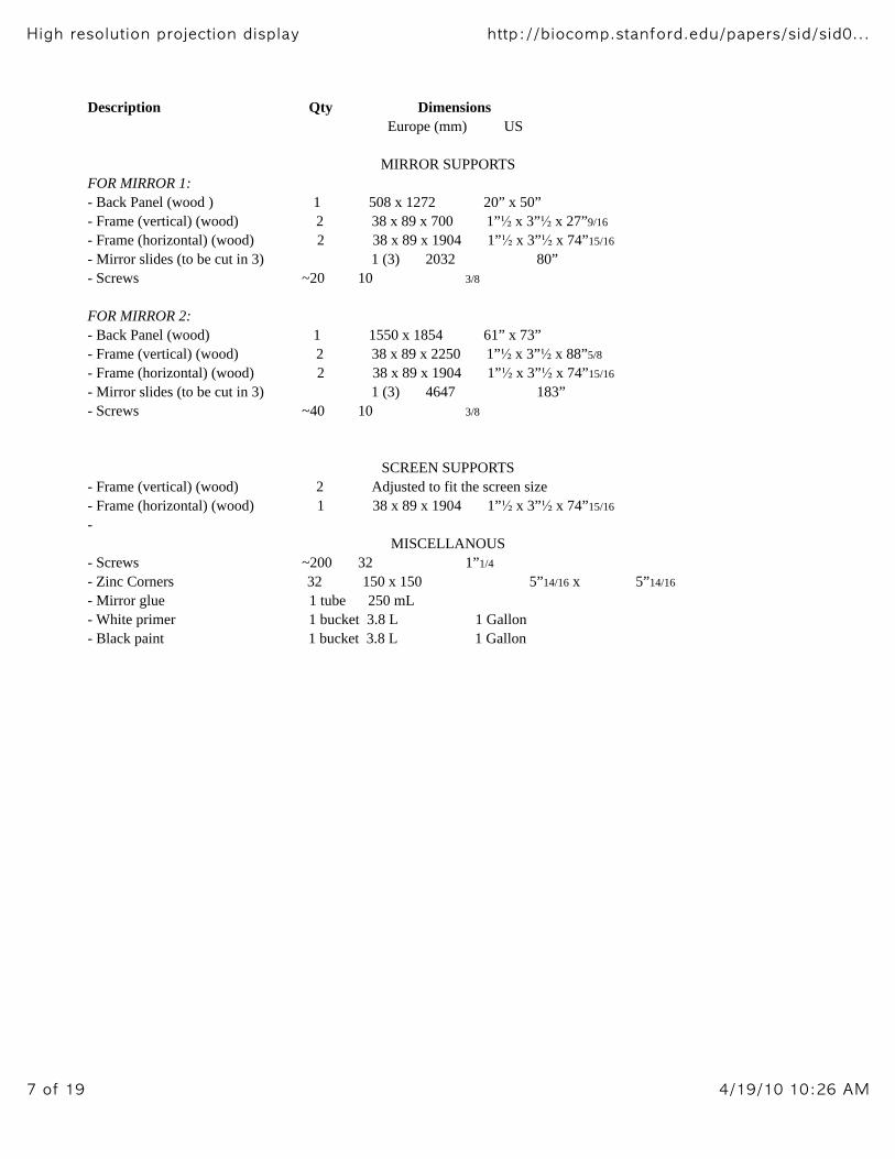
Description Qty Dimensions
Europe (mm) US
MIRROR SUPPORTS
FOR MIRROR 1:
- Back Panel (wood ) 1 508 x 1272 20” x 50”
- Frame (vertical) (wood) 2 38 x 89 x 700 1” x 3” x 27”9/16
- Frame (horizontal) (wood) 2 38 x 89 x 1904 1” x 3” x 74”15/16
- Mirror slides (to be cut in 3) 1 (3) 2032 80”
- Screws ~20 10 3/8
FOR MIRROR 2:
- Back Panel (wood) 1 1550 x 1854 61” x 73”
- Frame (vertical) (wood) 2 38 x 89 x 2250 1” x 3” x 88”5/8
- Frame (horizontal) (wood) 2 38 x 89 x 1904 1” x 3” x 74”15/16
- Mirror slides (to be cut in 3) 1 (3) 4647 183”
- Screws ~40 10 3/8
SCREEN SUPPORTS
- Frame (vertical) (wood) 2 Adjusted to fit the screen size
- Frame (horizontal) (wood) 1 38 x 89 x 1904 1” x 3” x 74”15/16
-
MISCELLANOUS
- Screws ~200 32 1”1/4
- Zinc Corners 32 150 x 150 5”14/16 x 5”14/16
- Mirror glue 1 tube 250 mL
- White primer 1 bucket 3.8 L 1 Gallon
- Black paint 1 bucket 3.8 L 1 Gallon

OUTSIDE VIEW
This system is designed for a 90 inch creen, dimensions (mm), ratio 4/3:
width : 1829.3
Height: 1372
The side panels are in thin wood and painted in black. The video projector is posed on the bottom of the
system. Since the beam goes out of the machine making an angle of 13 degrees with the horizontal if it is posed as is on
the floor, we need to set the position of the video projector such that the beam goes out in an horizontal manner. We built
a support underneath the video projector to hold it in the correct position, the beam lighting in the correct direction
(horizontal).

MAIN FRAME
The main frame was built in redwood and special cuts were made at each angle to make the whole structure
stable. More stability is brought with the building of the inner structures such as the two mirror supports and the screen
support. There are 4 zinc corners and many screws at each angle also. The structure is very strong and we can hang very
heavy panels on it without any fear.

MIRROR SUPPORTS
MIRROR 1
Equations (in mm):
b1.sin(beta) = 177 => b1 = 205.03
b2.cos(beta) = 400 – d1 = 149 => b2 = 294.96
b1 + b2 = 500
500.sin(beta) = 431.63
500.cos(beta) = 252.37
Configuration:
The assembly of the different parts of the wood support for this
mirror is the same as the one depicted for the second mirror (see the figure in the configuration part of the description of
the second mirror).
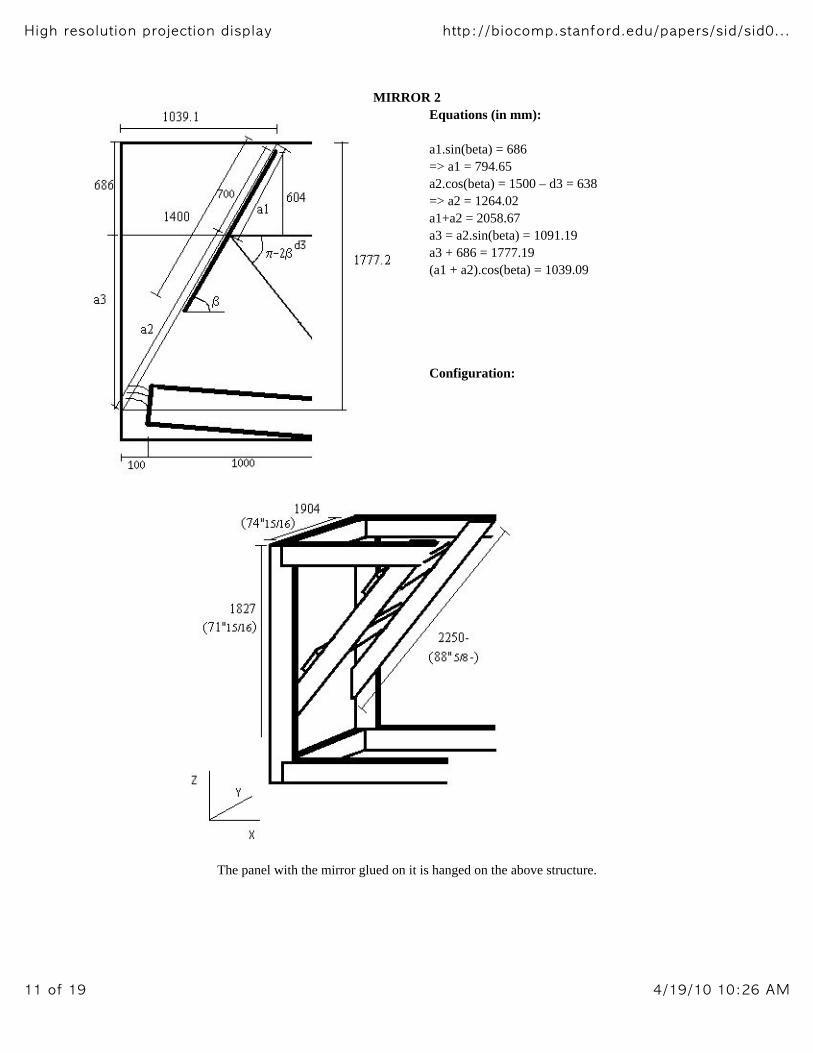
MIRROR 2
Equations (in mm):
a1.sin(beta) = 686
=> a1 = 794.65
a2.cos(beta) = 1500 – d3 = 638
=> a2 = 1264.02
a1+a2 = 2058.67
a3 = a2.sin(beta) = 1091.19
a3 + 686 = 1777.19
(a1 + a2).cos(beta) = 1039.09
Configuration:
The panel with the mirror glued on it is hanged on the above structure.

SCREEN SUPPORTS
The screen supports were designed to fit the screen we were using (Draper screen). The shape of the screen,
and the way to hang it depend highly on the case. The wood was arranged to make a solid and stable structure the hang
the screen.
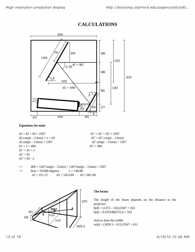
CALCULATIONS
Equations (in mm):
d1 + d2 + d3 = 2567 d1’ + d2’ + d3’ = 2567
d2.cos(pi – 2.beta) + x = d3 d3’ = d2’.cos(pi – 2.beta)
d2.sin(pi – 2.beta) = 1267 d2’.sin(pi – 2.beta) = 1267
d1 + x = 400 d1’ = 400
d1’ = d1 + x
d2’ = d2
d3’ = d3 - x
=> 400 + 1267/sin(pi – 2.beta) + 1267/tan(pi – 2.beta) = 2567
=> beta = 59.686 degrees x = 148.88
d1 = 251.12 d2 = 1453.89 d3 = 861.98
The beam:
The height of the beam depends on the distance to the
projector:
h(d) = (1372 – 165)/2567 + 165
h(d) = 0.4701986755.d + 165
And so does the width:
w(d) = (1829.3 – 611)/2567 + 611

w(d) = 0.4746136736.d + 611
QUESTIONS AND ANSWERS
Q: Does the beam touch the ground?
A: No
The beam touches the ground for h(d)/2 = 177, that is to say d = 401.96, which is much more than d1.
Q: Does the beam collide with the video projector?
A: No
Because h(d1+b)/2 < c (see figure below)
d1 = 251.12
b = V(110*110 + d1*d1).cos(pi – 2.beta – Atan(110/d1))
c = V(110*110 + d1*d1 – b*b)
b = 136.85
h(d1+b)/2 = 173.55
c = 237.93
h(d1+b)/2 < c
Q: Is Mirror 1 big enough?
A: Yes
IN HEIGHT:
Because h(d1 + x) = 353.08 < M1.sin(beta) = 431.63
IN WIDTH:
Because w(d1 + x) = 800.84 < Width of M1 = 1000
Q: Is Mirror 2 big enough?
A: Yes
IN HEIGHT:
Because h(d1 + d2 + y)/2 < M2*cos(pi/2 – beta)/2 (see figure below)
y = M2.sin(pi/2 – beta)/2 = 353.31
M2.cos(pi/2 – beta)/2 = 604.29
h(d1 + d2 + y)/2 = 566.4
h(d1 + d2 + y)/2 < M2.cos(pi/2 – beta)/2
IN WIDTH:
Because w(d1 + d2 + y) = 1587.91 < Width of M2 = 1800

Q: Does everything fit in the box, Fred?
A: It sure fits!
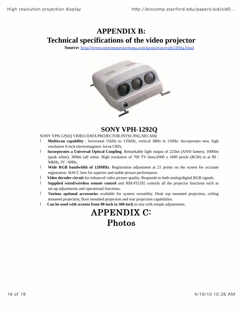
APPENDIX B:
Technical specifications of the video projectorSource: http://www.extremeprojections.com/projectors/vph1292q.html
SONY VPH-1292QSONY VPH-1292Q VIDEO DATA PROJECTOR (NTSC/PAL/SECAM)
Multiscan capability : horizontal 15kHz to 135kHz, vertical 38Hz to 150Hz. Incorporates new, high
resolution 9-inch electromagnetic focus CRTs.
Incorporates a Universal Optical Coupling. Remarkable light output of 225lm (ANSI lumen), 1000lm
(peak white), 300lm (all white. High resolution of 700 TV lines/2000 x 1600 pixels (RGB) in at fH :
94kHz, fV : 60Hz.
Wide RGB bandwidth of 120MHz. Registration adjustment at 21 points on the screen for accurate
registration. HACC lens for superior and stable picture performance.
Video decoder circuit for enhanced video picture quality. Responds to both analog/digital RGB signals.
Supplied wired/wireless remote control unit RM-PJ1292 controls all the projector functions such as
set-up adjustments and operational functions.
Various optional accessories available for system versatility. Desk top mounted projection, ceiling
mounted projection, floor mounted projection and rear projection capabilities.
Can be used with screens from 90-inch to 300-inch in size with simple adjustments.
AAPPPPEENNDDIIXX CC::
PPhhoottooss


APPENDIX D:
Useful links
Description of the SONY video projector:
http://www.extremeprojections.com/projectors/vph1292q.htmlDraper, rear projection screen maker:
http://www.draperinc.com/projection.htmlAbout caves and VR projection-based environments:
http://www.evl.uic.edu/EVL/VR/
Selecting the Right Rear Projection Screen Surface:
http://www.da-lite.com/Education/Manuals/RearProj/rearpage10-12.html
To adjust the display:
http://orpheus.ucsd.edu/mediaservices/testpattern/main.htm
Link to the Electronic Visualization Laboratory:
http://www.evl.uic.edu/EVL/VR/