ttv 1100 gb 01022010 - proquipnz.co.nz · introduction 4 ttv 1100 1 introduction this operating...
TRANSCRIPT

Operating manual (Translation of the original version)
TTV 1100
Stolzenberg GmbH & Co. KG
Reinigungsmaschinen - Maschinenbau
Hamburger Str. 15 - 17
49124 Georgsmarienhütte
Telefon +49 (0 54 01) 83 53-0
Telefax +49 (0 54 01) 83 53-11
E-Mail: [email protected]
Internet: www.stolzenberg.de


Table of contents
TTV 1100 I
Table of contents
1 Introduction....................................................................................................................................... 4
1.1 Usage conformant with intended purpose .......................................................................... 4
2 Safety information............................................................................................................................ 5
3 Device Description ........................................................................................................................... 7
3.1 Initial Startup ................................................................ Fehler! Textmarke nicht definiert.
4 Operation........................................................................................................................................... 9
4.1 Driving ................................................................................................................................. 9
4.1.1 Safety information................................................................................................ 9
4.1.2 Starting the Sweeping & Suction Machine .......................................................... 9
4.1.3 Cold start: ............................................................................................................ 9
4.1.4 Driving forward: ................................................................................................. 10
4.1.5 Driving backwards: ............................................................................................ 10
4.2 Sweeping .......................................................................................................................... 10
4.2.1 Operatting the Sweeping Rollers....................................................................... 10
4.2.2 Operating the Filter Cleaning Device ................................................................ 11
4.2.3 Operating the Side Brushes .............................................................................. 11
4.2.4 Operating the Suction........................................................................................ 12
4.3 Adjustment of Driver`s Seat .............................................................................................. 12
4.4 Turning Off the Sweeping & Suction Machine .................................................................. 12
4.5 Operating the Filter Cleaning Device................................................................................ 13
4.6 Emptying the Dust Container ............................................................................................ 13
4.6.1 Removing the Dust Container ........................................................................... 13
4.6.2 Reinserting the Dust Container ......................................................................... 14
5 Service and Maintenance .............................................................................................................. 15
5.1 Safety Information............................................................................................................. 15
5.2 Cleaning ............................................................................................................................ 15
5.3 Brake................................................................................................................................. 16
5.3.1 Adjusting the Brake ........................................................................................... 16
5.4 Brake Check ..................................................................................................................... 17
5.4.1 Correct Operating of Brake................................................................................ 17
5.5 Wheels .............................................................................................................................. 17
5.6 Steering............................................................................................................................. 17

Table of contents
II TTV 1100
5.7 Removing the main trim panel (hood)............................................................................... 18
5.7.1 Lifting off the hood ............................................................................................. 18
5.7.2 Replacing the hood............................................................................................ 18
5.8 Replenishing operating fluids............................................................................................ 18
5.8.1 Checking the hydraulic oil filling level................................................................ 19
5.8.2 Replenishing fuel ............................................................................................... 20
5.9 Safety information regarding hydraulics ........................................................................... 20
5.10 Replacement of Filter........................................................................................................ 21
5.10.1 Removal............................................................................................................. 21
5.10.2 Reinsertion ........................................................................................................ 22
5.11 Sweeping Rollers Replacement........................................................................................ 22
5.11.1 Dismounting the Sweeping Rollers ................................................................... 22
5.11.2 Installing the Sweeping Rollers ......................................................................... 23
5.12 Setting the Sweeping Rollers............................................................................................ 24
5.12.1 Sweeping Contour Adjustment .......................................................................... 24
5.12.2 Adjusting the Sweeping Contour ....................................................................... 24
5.12.3 Further Possible Adjustment: ............................................................................ 25
5.13 Replacing the Side Brush ................................................................................................. 26
5.13.1 Dismounting the Side Brush.............................................................................. 26
5.13.2 Mounting the Side Brush ................................................................................... 26
5.14 Adjustment of the Side Brush ........................................................................................... 26
5.15 Maintenance Chart............................................................................................................ 28
5.15.1 Daily maintenance ............................................................................................. 28
5.15.2 After each 50 operating hours also ................................................................... 28
5.15.3 After each 100 operating hours also ................................................................. 28
5.15.4 After each 200 operating hours also ................................................................. 29
5.16 Disturbances, Disturbance Display, Remedy ................................................................... 29
5.17 Technical Data .................................................................................................................. 30
5.18 Product Certification.......................................................................................................... 32
5.19 Disposal ............................................................................................................................ 32
5.20 Accessories and spare parts ............................................................................................ 32
5.21 Service .............................................................................................................................. 32
5.22 Transport........................................................................................................................... 33
6 EC Declaration of conformity (Translation of the original version) .......................................... 34

Table of contents
TTV 1100 III

Introduction
4 TTV 1100
1 Introduction
This operating manual contains instructions for using the hand-operated
sweeper.
Our products are subject to continuous improvement. Therefore, design
changes that were made after this manual went to print could not be
incorporated. If you have any questions, please contact our Service
department.
The operating manual must be read and applied by all persons who
operate the sweeper.
Apart from the operating manual and the regulations for accident pre-
vention applicable in the country of use and the location of use, the
common, recognised rules for safe and technically correct working must
also be followed.
1.1 Usage conformant with intended purpose
The appliance is intended exclusively for sweeping on solid surfaces (for
example.: parking areas, walkways, shop floors). The area to be swept
should not be wet.
The sweeper may only be used by reliable and instructed personnel.
revent children, juveniles and other unauthorised persons from using the
machine (e.g. by pulling out the key after use).
Any other use, or any use over and above that, will be considered to be
non-conformant with intended purpose. The manufacturer rejects any
and all liability for damage resulting from such use. The risk is that of the
user alone.
Usage conformant with intended purpose also includes compliance with
the operating manual and the inspection and maintenance specifica-
tions. Drive the sweeper only along expressly marked routes and
spaces.

Safety information
TTV 1100 5
2 Safety information
1. The machine should only be used in a flawless state, as
well as in keeping with its intended purpose, in a safety-
conscious and risk-conscious manner and in compliance
with these operating instructions.
2. In addition to the operating manual, please heed general le-
gal and other binding regulations for accident prevention
and environmental protection.
3. Sweeping and picking up of flammable, toxic or explosive
substances, along with flammable gases or diluted acids
and solvents, burning or smouldering objects is prohibited!
4. The appliance is not suitable for picking up fluids, cables,
cords, wires or the like.
5. The machine should only be used with the dust box fitted to
prevent injuries caused by parts being slung out.
6. Transporting loads with the sweeper is not allowed.
7. Faults should be eliminated immediately, particularly those
that could impair safety.
8. Do not make any changes, modifications or additions to the
sweeper without the approval of the manufacturer.
9. Replacement parts must meet manufacturer specifications.
This is always ensured by using original replacement parts.
10. Ensure that operating media, auxiliary media and replace-
ment parts are disposed of in a safe and environmentally-
friendly manner, particularly batteries!
11. Suitable non-slip footwear should be worn to avoid acci-
dents.
12. If you have any questions, please contact our Service de-
partment.
13. Persons (including children) who are not able to use this
machine safely due to their physical, sensory or mental ca-
pabilities or their inexperience or lack of knowledge may not
use this machine without the supervision or instruction by a
responsible person! Children should be supervised to en-
sure that they do not play withthe appliance.
14. Caution: loose clothing can be caught and drawn in on rotat-
ing parts.
15. Observe the maximum climbing capability and maximum
permissible slant specified in the technical data when driv-
ing transversely to an incline. The unit can topple over if the

Safety information
6 TTV 1100
steering is turned too sharply, particularly on inclines. Adjust
your driving style and speed to suit conditions.
16. The machine is not approved for use on roads or streets.
17. Warning: risk of crushing. Maintain a safety clearance of 2
metres to other people during emptying through high dump-
ing.
18. Maintenance and repair work on the hydraulics and high
dumping mechanism should only be entrusted to a special-
ist firm.
19. Personal safety equipment, particularly hearing protection,
must be worn when operating the machines.
20. The machine should only be used outdoors or in ade-
quately-ventilated rooms.
21. Removal of the motor filter while the motor is running can
lead to a sudden increase in motor speed. This applies in
particular if the filter is dirty or blocked in another manner.
22. Work using the unit should be interrupted at regular inter-
vals.
23. Observe general guidelines relating to explosive, inflamma-
ble and highly flammable fuels. Particular care should be
exercised when filling the machine with fuel to ensure that
the motor is deactivated and cold, and that filling is only re-
alised outdoors or in a well-ventilated location.
24. Warning: parts of the machine become hot during use.
There is a risk of burn injuries.

Device Description
TTV 1100 7
3 Device Description
The Sweeping & Suction Machine is driven hydraulically by an internal
combustion engine.
Model TT/V 900 operates by using a pivotable side brush to convey the
sweepings to the two sweeping rollers arranged parallel to the direction
of motion. These project the sweepings overhead into the dust container
positioned behind it.
Optionally two side brushes may be installed. Model TT/E 1100 is
equipped with two pivotable side brushes. If necessary, the dust stirred
up by the sweeping rollers is caught by the dust suction unit in a lamel-
lar filter inside the machine. The lamellar filter is cleaned by an electri-
cally controlled filter cleaning device.
1 Battery check light 2 Switch for the sweeping
rollers
3 Switch for the side brushes 4 Switch for filter cleaning
5 Speed control for the motor 6 Suction control
7 Lowering lever for the
sweeping rollers
8 Cold starting device
9 Key-operated switch
1 steering wheel with steer-
ing pillar
2 driver`s seat
3 main trim panel
4 steering pillar trim
5 dust container
6 front trim panel
7 driving wheel
8 left side trim panel
9 rear wheel with drum break
10 lowering lever for side
brushes
11 pivotable side brushes

Device Description
8 TTV 1100
3.1 Initial Startup
The Sweeping & Suction Machine is supplied with batteries
Standard:
� Open the transport packaging.
� Take off the complete hood. Lift up hood at back and lift the front
spigots of the hood out of the retaining.
� Fit in the batteries.
� Replace the hood panel.
� Mount the side brushes.
� The Sweeping & Suction Machine is ready for use.
� Drive the Sweeping & Suction Machine over a ramp out of the trans-
port packaging.
Use a unit ramp. The ramp must be designed in such a way as to allow
the rear wheel as well as the drive wheels to travel across it.
If this is not observed, damages to the Sweeping & Suction Machine
mechanics will occur.
1 Unit Ramp

Operation
TTV 1100 9
4 Operation
4.1 Driving
4.1.1 Safety information
The motor must be started from the driver's seat only.
The motor must not be started by short-circuiting the electric connectors
at the starter: Otherwise the machine may begin to move immediately!
4.1.2 Starting the Sweeping & Suction Machine
� Sit down in the driver's seat.
� Do not press the accelerator-pedal during starting procedure.
� Press down the brake pedal
1 Parking brake 2 Brake pedal
3 Accelerator pedal for- and
backwards (wig-wag)
4.1.3 Cold start:
Cold starting is necessary, if the Suction & Sweeping Machine has not
been used for some time and/or at cold outdoor temperatures.
To do a cold start, proceed like this:
� Pull the knob of the cold starting device all the way up.
� Set the motor speed lever to idle speed.
� Start up the Suction & Sweeping Machine.
� Let the motor run.
Do not allow the motor to run in a closed space.
Danger of poisoning by exhaust fumes!!
When the motor is running smoothly:
DANGER!

Operation
10 TTV 1100
� Push the knob of the cold starting device downward.
� Adjust the speed to operating speed. (motor speed control to the
very front position).
4.1.4 Driving forward:
� Start up the Suction & Sweeping Machine
� Step on the brake.
� Push the driving direction switch forward.
The drive-system only can be operated when speed control for the mo-
tor is pushed to working-rpm (flywheelclutch).
� Carefully step on the accelerator (forward).
4.1.5 Driving backwards:
� Carefully step on the accelerator (backwards)
1 Forwards 2 Backwards
4.2 Sweeping
4.2.1 Operatting the Sweeping Rollers
� Start the Sweeping & Suction Machine.
� Switch the toggle switch for the sweeping rollers to ON Position.
� Unlatch the lowering lever of the sweeping roller.
Stopping Sweeping Rollers Operation.
� Pull lowering lever of the sweeping rollers towards yourself.
� Switch toggle switch for the sweeping rollers to OFF position.
� Let the lever snap in arresting position.

Operation
TTV 1100 11
1 Battery check light 2 Switch for the sweeping roll-
ers
3 Switch for the side brushes 4 Switch for filter cleaning
5 Speed control for the motor 6 Suction control
7 Lowering lever for the sweep-
ing rollers
8 Cold starting device
9 Key-operated switch
4.2.2 Operating the Filter Cleaning Device
The filter cleaning device prevents the lamellar filter from being blocked
by debris.
� The suction can be stopped by shutting down the motor or by clos-
ing the suction cover.
� Depress the toggle switch for the filter cleaning device for about 5 to
10 seconds.
� The filter cleaning device begins operation.
4.2.3 Operating the Side Brushes
The side brushes are fixed to swingers. Whenever the side brushes hit
an obstacle they swing back under the vehicle to avoid damages.
� Start the Sweeping & Suction Machine.
� Unlatch the lowering lever of the side brushes.
� Switch toggle switch for the side brushes to ON position.
� Push the lever down.
Stopping Side Brush Operating.
� Pull up the lowering lever for the side brushes.
� Switch toggle switch for the side brushes to OFF position.
� Let the lever snap in arresting position.

Operation
12 TTV 1100
4.2.4 Operating the Suction
The suction prevents dust formation duringsweeping operations.
� Start the Sweeping & Suction Machine.
� Push the suction control forward to open the cover of the suction.
To avoid damage to the filter, use the lever to close the cover be-
fore picking up wet sweepings!
� Depress the toggle switch for the filter cleaning device for about 5 to
10 seconds.
� The filter cleaning device begins operation.
4.3 Adjustment of Driver`s Seat
� Loosen the seat arresting device and shift the driver's seat on the
seat support to a position that feels comfortable to you.
4.4 Turning Off the Sweeping & Suction Machine
� Depress the brake pedal.
� Lock the brake by pulling the locking lever towards the driver's seat.
When the brake now is relieved the brake pedal must remain in de-
pressed position.
All of the pilot lamps on the switch are off.
� Switch off all actuators.
� Lift up the side brushes and arrest the lowering lever for the side
brushes.
� Lift up the sweeping rollers and arrest the lowering lever for the
sweeping rollers.
� Turn the key counterclockwise and remove it from the key switch.
� Turn the battery master switch counterclockwise and remove it from
the socket.
CAUTION!

Operation
TTV 1100 13
4.5 Operating the Filter Cleaning Device
The filter cleaning device prevents the lamellar filter from being blocked
by debris.
� Close the exhaust flaps.
� Wait until ventilation wheel stands still.
� Apply filter cleaning device at regular intervals.
� Depress the toggle switch for the filter cleaning device for about 5 to
10 seconds.
The filter cleaning device begins operation.
4.6 Emptying the Dust Container
The dust container is the place where the sweepings are collected.
It is positioned at the back of the Sweeping & Suction Machine.
The dust container must be emptied regularly and especially after each
use.
4.6.1 Removing the Dust Container
Turn the dust container locking upward.
Pull out the dust container from the Sweeping – & Suction Machine by
the gripping handle until the front dust container guide rails are free.
1 locking device 2 recessed grip
3 locking device 4 guide rail
5 dust container guides 6 roller
At the back of the dust container two guiding rollers are installed to
make the removal easier.
� Lower the dust container to the ground
Operation
14 TTV 1100
A number of rollers and a recessed grip are positioned at the bottom of
the dust container.
� Remove the dust container completely from the Sweeping & Suction
Machine.
� In order to empty the dust collecting box use the free hand to take
hold of the recessed grip.
� The sweepings are discharged through the opening at the bottom of
the dust bin.
� Empty sweepings into appropriate containers only.
4.6.2 Reinserting the Dust Container
� Place the dust container before the dust container retaining.
� Bring the dust container's front guides up to the same level as the
guide rails.
� Slide the dust container into the Sweeping & Suction Machine.
� Turn the locking device downward.
Service and Maintenance
TTV 1100 15
5 Service and Maintenance
5.1 Safety Information
Only complete the type of maintenance work described in the following
chapter. All other maintenance and upkeep work may only be carried
out by the manufacturer or by companies and persons authorised by the
manufacturer, who are familiar with the relevant safety specifications,
because portable devices in industrial use are subject to the safety test
according to VDE 0701.
Closely follow the steps listed in the maintenance instructions. The im-
proper completion of maintenance tasks may result in malfunctions
when using the sweeper and may possibly render the warranty granted
null and void.
Disconnect the spark plug when working on the engine Observe the
machine's safety stickers!
Maintenance work/ troubleshooting at the electric motor must not be
done while the electric motor is running.
Use only flawless and appropriate tools to complete maintenance work.
Note the requirements for spare parts (see Spare parts).
If covers and/or safety devices were removed during maintenance
work/repairs, they will have to be reattached prior to starting the
sweeper.
For carrying out any work on the sweeper, it must be switched off and
secured from rolling away by accident.
The open hood always has to be secured by the hood arresting device.
5.2 Cleaning
The suction sweeper may only be cleaned in the off state, when it is dry.
The suction sweeper is a machine with electrical components.
Moisture damages the eletronics of the device. Moisture can result
in leakage currents and short-circuits.!
Do not use any high-pressure cleaners
WARNING

Service and Maintenance
16 TTV 1100
5.3 Brake
The brake is a component affecting operational safety. All work
pertaining to the maintenance and replacement of brake parts must
be executed by professionally trained personnel!
The brake (drum brake) acts on the rear wheel and is controlled via
Bowden pull wire by the brake pedal.
The brake adjustment is situated on the right side of the rear wheel fac-
ing in driving direction.
5.3.1 Adjusting the Brake
� Hold the adjustment nut of the Bowden pull wire in place with a
wrench.
� Loosen the back nut of the Bowden pull wire.
� Push the brake lever upward until the brake lever is obstructed.
� Hold the brake lever in this position.
� Tighten the back nut of the Bowden pull wire.
1 Bowden pull wire guiding 2 Bowden pull wire
3 adjustment nut 4 back nut
5 brake pulley 6 brake lever
7 brake pulley arresting
Now conduct a brake check.
DANGER!

Service and Maintenance
TTV 1100 17
5.4 Brake Check
Free Movement of Rear Wheal
You must be able to move the Sweeping & Suction Machine by pushing
when the brake is released.
The rear wheel must not be blocked. Brakes that are set too tightly
damage the brake drum.
5.4.1 Correct Operating of Brake
Carefully drive a few meters at moderate speed.
Depress the brake pedal. The Sweeping & Suction Machine must stop.
If the brake check should not render a satisfying result the setting pro-
cedure must be repeated.
Further Setting Possibility:
The Bowden pull wire does not allow tightening in the way described
above any longer.
� Loosen the brake pulley arresting.
� Lift the brake lever up until it is obstructed.
� Hold the brake lever in this position.
� Pull the brake pulley down and push the brake pulley arresting up-
ward.
� Fasten the brake pulley arresting.
� Carry out the above described brake check.
5.5 Wheels
The Sweeping & Suction Machine is equipped with three wheels.
The standard rear wheel tire is made of solid rubber.
The two drive wheels are standard equipped with pneumatic tires.
Optionally the drive wheels are delivered sith solid rubber tires.
Defective tires must be repaired or replaced by expert shops only.
Deliver the complete wheel (rim and tire) to the tire shop.
5.6 Steering
The steering transferral to the rear wheel is man aged by a chain and
two chain sprockets.
Grease the chain sprockets at regular intervals. Cf. Maintenance Chart.

Service and Maintenance
18 TTV 1100
5.7 Removing the main trim panel (hood)
The hood of the Suction & Sweeping Machine can be removed for main-
tenance and repair work purposes.
5.7.1 Lifting off the hood
� Pull the key out of the key-operated switch.
� Open the hood.
� Lock the hood against unintentional shutting.
� Insert the hood arresting into the hole.
� Disconnect the plug connection for the contact switch of the driver's
seat.
� Close the hood.
� Reach underneath the driver's seat and to the rear edge of the
hood.
� Lift up the hood.
� Remove the hood
5.7.2 Replacing the hood
� Reach underneath the driver's seat and to the rear edge of the
hood.
� Lift up the hood.
� Put the hood in place on the Suction & Sweeping Machine.
� At the front edge of the hood there are two locating pins.
� Insert these pins into the receptacles in the floor panels.
� Open the hood.
� Lock the hood against unintentional shutting.
� Insert the hood arresting into the hole.
If the plug connectors are not connected, the Suction & Sweeping Ma-
chine cannot be started.
� Close the hood
5.8 Replenishing operating fluids
Safety information for handling operating fluid
Do not keep easily combustible materials such as fuel, matches, or simi-
lar, in the vicinity of a running motor.
Only replenish fuel in an open or well ventilated place.

Service and Maintenance
TTV 1100 19
Fuel is highly combustible and explosive!
Only replenish fuel at motor stand-still!
There must not be any fuel in the filler cap! Do not overfill the tank!
Make sure the tank cap is closed.
Do not smoke, and keep away open fire while filling the tank and in the
fuel storage area.
Remove spilled fuel immediately in the vicinity of the motor!
Wait before starting the motor until the petrol fumes have evaporated!
Observe the specified oil and fuel qualities (see page 29 Technical Data
Filling Substances) and store all of these substances in certified con-
tainers only.
Be careful when draining hot oil.
Danger of burning.
Dispose of used oil according to legal requirements.
5.8.1 Checking the hydraulic oil filling level
� Open the hood.
On the left hand side of the machine, seen in travel direction, the hy-
draulic pump is positioned. Next to this pump, there is a hydraulic tank
containing 1 litre of hydraulic oil. If the level of the hydraulic oil can be
seen in the middle of the two markings “min” and “max”, the oil-level is
correct.
If the oil-level is below “min”, hydraulic-oil will have to be filled up.
1 Rear-axle motors 2 Rear-axle motors
3 Hydraulic-tank 4 Max
5 Min 6 Hydraulic Pump
� Unscrew the cap of the hydraulic tank.
� Place a clean funnel into the tank carefully add hydraulic oil (HLDP
46 oder HLP 46) until the level reaches middle-position between
“min” and “max”
CAUTION!

Service and Maintenance
20 TTV 1100
� Remove the funnel and close the cap of the hydraulic tank.
� Check oil-level after some minutes of operation of the machine
5.8.2 Replenishing fuel
� Switch off the Suction & Sweeping Machine.
� Allow the motor to cool down.
� Open the hood.
� Unscrew the tank filler cap.
� Place a clean funnel into the tank filler neck.
� Pour in a little fuel and wait until the fuel has drained from the fun-
nel.
� Repeat this process until the tank has been filled.
� Remove the funnel from the tank filler neck.
� Close the tank.
� Should fuel have been spilled, wipe it away.
5.9 Safety information regarding hydraulics
All work on the hydraulic system has to be carried out by skilled person-
nel or persons charged with this work. Please contact the manufacturer.
The hydraulic system operates under high pressure!
Do not change the adjustment of the overpressure valves!
Hydraulic oil escaping under pressure can permeate through the skin
causing severe injuries.
(Consult a doctor at once, in case of injury by pressure oils. Otherwise
severe infections may ensue).
Danger of being burnt (!) by hydraulic oil when draining oil at operating
temperature !
Hydraulic lines require visual inspection at regular intervals.
Use suitable safety equipment to prevent injuries.
Replace hydraulic hoses immediately in case of
� damage to the exterior layer reaching to the inner lining (e.g. chafe
marks, tears, cuts)
� embrittlement of the exterior layer (fissures in the hose material)
� deformations of hydraulic lines, in pressureless state or pressure
loaded, that deviate from the natural shape of the hoses.

Service and Maintenance
TTV 1100 21
� deformations at bends such as squeezes, kinks, separation of lay-
ers, bubbles.leaks.
Use spare parts complying with the requirements specified
by the manufacturer only. This will always be the case,
if original spare parts are used.
5.10 Replacement of Filter
The filter removes fine dust.
The filter is cleaned by an electrical vibrating device.
5.10.1 Removal
� Open the hood.
� Lock hood securely using the hood arrester.
The filter is held in the fixture by 4 star handles.
1 star handle 2 star handle
� Loosen the top two star handles.
� Swing up the top angular bracket.
� Loosen the bottom two star handles.
� Pull the filter out of the fixture.

Service and Maintenance
22 TTV 1100
5.10.2 Reinsertion
� Place the filter into the lower angular bracket.
� Swing the upper bracket over the filter..
� Tighten the top star handles slightly.
� Tighten star handles evenly crosswise so that the filter snugly fits all
around the seal.
� Adjust the bolts and the nuts in a way that, provides the filter with
the best possible sealing inside the casing.
1 star handle
2 angular brackets
3 filter (see sticker)
5.11 Sweeping Rollers Replacement
5.11.1 Dismounting the Sweeping Rollers
� Turn off the Sweeping & Suction Machine.
� Switch off the EMERGENCY OFF to avoid accidental starting.
� Pull lowering lever of the sweeping rollers.
� Arrest the lowering lever.
� Loosen the bolts of the left side trim panel facing in driving direction.
1 fastening bolts of side trim panel

Service and Maintenance
TTV 1100 23
� Remove the side panel.
The roller swing is held in place by three star handles.
� Loosen the star handles.
� Remove the roller swing.
1 open star handle 2 star handle with marking
3 roller swing 4 star handle
5 turning lever
� Pull the sweeping rollers out of the machine and remove any debris,
cords, etc., from the roller tunnel and from the pick-up pins.
5.11.2 Installing the Sweeping Rollers
� Push the sweeping rollers under the machine.
Observe the sweeping rollers' sense of rotation while sliding them in.
1 forward drive 2 direction of motion of the
sweeping rollers
Each roller end is equipped with a keyway.
Turn the sweeping roller until the pick-up pin of the rear roller swing fits
into the keyway of the sweeping roller.
Slide the sweeping rollers in as far as possible.
Set the front roller swing onto the free sweeping roller ends.
The roller swing is equipped with two turning levers.

Service and Maintenance
24 TTV 1100
Each turning lever end is equipped with one pick-up pin.
1 threaded rods 2 sweeping roller keyway
3 pick-up pin
� Turn the turning lever until the pick-up pin fits into the keyway of the
sweeping rollers.
� Push the roller swing over the threaded rods.
� Make sure the sweeping rollers are fitted on both sides by the key-
way into the pick-up pins and that all star handles are firmly tight-
ened.
� Fasten the side trim panel.
5.12 Setting the Sweeping Rollers
5.12.1 Sweeping Contour Adjustment
For best cleaning results and to ensure the highest possible device effi-
ciency, the sweeping rollers are equipped with a sweeping contour.
The sweeping contour should be set to approx. 50-60 mm at the rear
roller.
Establishing the Sweeping Contour:
Drive the Sweeping & Suction Machine to an area to be cleaned. Switch
on the sweeping rollers without moving the sweeping machine. Allow
the sweeping rollers to run for about one or two minutes without moving.
Lift the sweeping rollers. Stop sweeping rollers operation and drive for-
ward a few meters. The sweeping track visible on the ground is the
sweeping contour.
5.12.2 Adjusting the Sweeping Contour
� Switch off the Sweeping & Suction Machine.
� Pull lowering lever of the sweeping rollers.
� Arrest the lowering lever.
� Open the hood.
Service and Maintenance
TTV 1100 25
� Secure the hood position by the hood arresting device.
� Guide the hood arresting into the holes at the bottom of the hood.
� Remove the right side trim panel facing in the direction of motion.
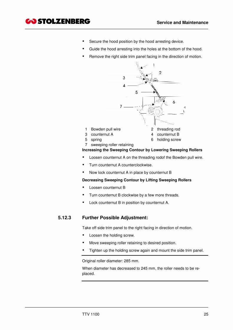
1 Bowden pull wire 2 threading rod
3 counternut A 4 counternut B
5 spring 6 holding screw
7 sweeping roller retaining
Increasing the Sweeping Contour by Lowering Sweeping Rollers
� Loosen counternut A on the threading rodof the Bowden pull wire.
� Turn counternut A counterclockwise.
� Now lock counternut A in place by counternut B
Decreasing Sweeping Contour by Lifting Sweeping Rollers
� Loosen counternut B
� Turn counternut B clockwise by a few more threads.
� Lock counternut B in position by counternut A.
5.12.3 Further Possible Adjustment:
Take off side trim panel to the right facing in direction of motion.
� Loosen the holding screw.
� Move sweeping roller retaining to desired position.
� Tighten up the holding screw again and mount the side trim panel.
Original roller diameter: 285 mm.
When diameter has decreased to 245 mm, the roller needs to be re-
placed.

Service and Maintenance
26 TTV 1100
5.13 Replacing the Side Brush
5.13.1 Dismounting the Side Brush
� Turn off the Sweeping & Suction Machine.
� Pull up the lowering lever for the side brushes.
� Arrest the lowering lever.
� Lift up the side brush motor in order to get easy access to the fas-
tening screws at the lower center of the side brush.
1 side brush motor 2 side brush trimming
3 shaft with keyway 4 flange base with locking
5 fastening screw
� Loosen the fastening screw at bottom center of each side brush.
� Pull the side brush down and off.
� Replace the side brush.
5.13.2 Mounting the Side Brush
� Fasten the flange plate to the side brush.
The flange plate is equipped with a locking.
The side brush motor shaft is equipped with a keyway.
� Turn the side brush until the feather key fits snugly into the keyway.
� Fasten the side brush to the shaft of the side brush motor by us of
the fastening screw.
5.14 Adjustment of the Side Brush
Operational wear necessitates additional adjustment of the side
brushes.
� Turn off the Sweeping & Suction Machine.
Service and Maintenance
TTV 1100 27
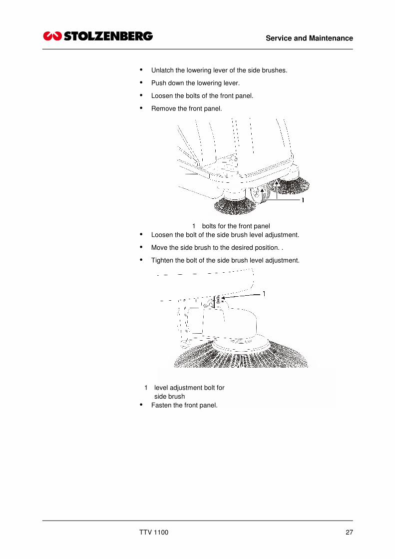
� Unlatch the lowering lever of the side brushes.
� Push down the lowering lever.
� Loosen the bolts of the front panel.
� Remove the front panel.
1 bolts for the front panel
� Loosen the bolt of the side brush level adjustment.
� Move the side brush to the desired position. .
� Tighten the bolt of the side brush level adjustment.
1 level adjustment bolt for
side brush
� Fasten the front panel.

Service and Maintenance
28 TTV 1100
5.15 Maintenance Chart
5.15.1 Daily maintenance
Check the sweeping roller tunnel to see if objects have been jammed or
dirt particles have seized up, diminishing the clear width of the sweeping
tunnel or obstructing free movement of the roller brushes
Check acid filling level of the battery and replenish distilled water, if ne-
cessary
Check oil filling level of the motor and replenish, if necessary
Check oil filling level of hydraulic system and replenish, if necessary.
Check the machine as to visual damages and correct operation.
Check the state of the dust filter and clean, if necessary Empty the dust
container.
Inspect hydraulic lines.
5.15.2 After each 50 operating hours also
Check acid concentration in the battery.
Clean and grease the battery poles.
Check tyre pressure, if air filled tyres are used.
Check if sweeping rollers are worn or obstructed by foreign objects and
replace, if necessary.
Check sweeping contour and readjust, if necessary.
Check if side brush adjustment is worn and readjust or replace, if nec-
essary.
5.15.3 After each 100 operating hours also
Check cable insulation and replace cables, if necessary.
Check all cable connections as to tightness.
Check brake pull and readjust, if necessary.
Check the profile of the tyres and replace tyres, if necessary.
Clean the dust filter and replace, if necessary.
Check dust suction as to foreign objects, and clean.
Do a test drive to check if all operational controls work.
Check whether the sweeping roller drive chain has been expanded too
much.
Check all bearings as to wear.
Check all seals as to damage and tightness.

Service and Maintenance
TTV 1100 29
5.15.4 After each 200 operating hours also
Subject the hydraulic motor to functional testing.
Renew hydraulic oil.
Check play of steering and tighten the chain, if necessary.
Check all electronic components as to contamination.
In addition
Observe the maintenance instructions provided by the manufacturer of
the motor. See annex
5.16 Disturbances, Disturbance Display, Remedy
Disturbance Possible Cause Remedy
No function indication at the con-
trol panel
Key-operated switch has not
been activated
Seat contact or hood contact
switch has not been activated
Flaw in electric connections
Battery empty
Turn the key-operated switch
check if load is OK
Check plug-in connections
Recharge the battery
Motor does not start (well): Battery empty
Cold start has not been pulled
Fuel tank empty
Low hydraulic oil filling level
Recharge battery or reverse
starting see section on "Starting
the Motor”
Replenish fuel.
Replenish hydraulic oil and repair
flaws / air leaks
Propelling drive out of operation /
low efficiency
Low hydraulic oil filling level Replenish hydraulic oil and repair
flaws / air leaks
Brush drive out of operation / low
efficiency
circuit-breaker dis-activated check reason for failure and only
afterwards
Re-activate circuit-breaker

Service and Maintenance
30 TTV 1100
Disturbance Possible Cause Remedy
Sweeping result not satisfactory Side brush(es) or sweeping
roller(s) not lowered
Side brush(es) or sweeping
roller(s) worn
Trajectory clogged by dirt
Sweeping roller(s) out of opera-
tion
Too much dust production
Filter heavily soiled
Filter not correctly fitted
Imperfect sealing causing false
air to be sucked in around the
filter area
Lower
Adjust / replace
Check if anything is jammed in-
side the roller casing
Inserted correctly? Is the motor
turning?
Switch off the side brushes, if
they are running
Open up the cover
Clean the filter
Check if it fits tightly
Check if false air is being sucked
in
5.17 Technical Data
Dimension and Weight
Length: approx. 1.450 mm
Width: 900 mm
Height: approx. 1165 mm upper edge of
steering wheel
Weight: 230 Kg
Sweeping Width
without side brush 700 mm
with one side brush 900 mm
with two side brushes 1.100 mm
Dust Container Volume 90 Ltrs.
Turning Radius 1,2 m
Climbing Capacity 20%
Speed 0-6 km/h
Filter Area 4 m²
Air Volume of the 900 m³
Dust Suction
supporting frame Steel construction, powder coated

Service and Maintenance
TTV 1100 31
Dimension and Weight
Trim Panel Parts impact resistant plastic
Drive motor Honda-Motor GX 200K1QXW-4
Weight: 16 kg
Cubic capacity 196 sqcm
Bore x stroke: 68 x 54 mm
Max. power output: 4,8 KW / 360 U/min
Max. torque: 1,35 kg-m
Hydraulic drive
Propelling drive Hydraulic motor OMP 50
Side brushes 12 V permanent-magnet DC-motor
90 W
Sweeping rollers 12 V permanent-magnet DC-motor
400 W
Filling Volumes
Fuel tank 3.6 l Unleaded fuel
Oil filling 0,5 l
Reducing gear unit Motor oil class
SG, SF SAE 10 W. 30
Hydraulic system: ~ 2 l HLDP 46
Maximum Airborne Sound Level
90 dB (A)
Weighted Effective Acceleration Value
Upper extremities are subjected to < 2,5 m/s2
Tires
Front: 1 solid rubber tire
Back: 2 pneumatic tires
Optional 2 solid rubber tires
Tire size: 260 x 85
Air pressure: 5,5 bar

Service and Maintenance
32 TTV 1100
Brake
Drum brake
Parking brake
Acting on front wheel
5.18 Product Certification
AufsitzkehrsaugmaschineTT/V 900/ 1100
Maximale Motorleistung: 4KWSeriennummer:Hersteller: Stolzenberg GmbH & Co. KGHamburger Str. 15-17, D-49124 GM-Hütte
5.19 Disposal
Dispose of faulty parts, especially electrical components, batteries and
plastic parts according to the locally applicable waste disposal specifica-
tions.
Used batteries must be disposed of according to Directive 2006/66/EC.
5.20 Accessories and spare parts
Accessories and spare parts must conform to the requirements of the
manufacturer. This is ensured by using genuine replacement parts.
5.21 Service
Stolzenberg GmbH & Co. KG
Hamburger Straße 15-17
D-49124 Georgsmarienhütte
Telefon: 0049 / (0)5401 83 53-0
Fax: 0049 / (0)5401 83 53-11
www.Stolzenberg.de

Service and Maintenance
TTV 1100 33
5.22 Transport
Transport the machine only in the switched-off condition, sufficiently well
fastened.

EC Declaration of conformity (Translation of the original version)
34 TTV 1100
6 EC Declaration of conformity (Translation of the original version)
according to the EC Machine Directive 2006/42/EC, Appendix II, No. 1A
Mr. Kai Stolzenberg – Management of the Stolzenberg GmbH & Co. KG, Hamburger Straße 15-17,
D-49124 Georgsmarienhütte - is authorized to arrange technical information.
We hereby declare that the machine described below corresponds, in its conception and construction, as well as the model brought into use by us, to the basic safety and health requirements of the EC Machine Directive 2006/42/EC. In case of a change being made that has not previously been agreed with us, this declaration will lose its validity.
Manufacturer: Stolzenberg GmbH & Co. KG,
Hamburger Straße 15-17, D-49124 Georgsmarienhütte
Designation of the machine: TTV 1100
Machine type: Suction sweeper with tandem-roller-system
relevant EC Directives: Directive 2006/42/EC
Directive 2000/14/EC
Directive 2004/108/EC
The following standards, in particular, were applied:
EN 292
EN 294
DIN EN 61000-6-2
DIN EN 60335-1
DIN EN 60335-2-69
DIN EN 60335-2-72
Georgsmarienhütte, 01.02.2010 ……………………………… Kai Stolzenberg
(Dipl. Wirtsch. Ing., Management)