tu1 reference manual · 2018-07-06 · conventions a number of conventions apply to tl/1 language...
TRANSCRIPT

TU1 Reference Manual
01991 John Fluke Mfg. Co., Inc.
All rights resewed. Lilho in U.S.A.
Advanced Test Equipment Rentalswww.atecorp.com 800-404-ATEC (2832)
®
Established 1981

CUSTOMER NOTICE
THROUGHOUT THIS MANUAL, ALL INSTANCES OF 9100A AND 9105A ALSO APPLY TO THE 91OOFT AND 9105FT.

Contents
Section Title Page
......................................................................... Where Am 13 XI
. Overview ............................................................................... 1 1
1 . 1 . INTRODUCTION ......................................................... 1-1 1.2. ORGANIZATION OF THIS MANUAL ............................. 1-2
TLI1 Language Conventions ............................................ 2-1
NAME CONVENTIONS ........................................ 2-2 File and Directory Names ................................... 2-3 Program Names ...................................................... 2-4 Device Names ........................................................ 2-4 Device List ............................................................. 2-6 Reference Designator Names ................................. 2-7 Ref Pin Names ....................................................... 2-7
DATA TYPES ............................................................. 2-8 Numeric ................................................................. 2-8 Floating-point ........................................................ 2-9 String .................................................................... 2-10
ARRAYS .................................................................... 2-11 OPERATORS ............................................................. 2-11
Arithmetic Operators ............................................... 2-12 Relational Operators ............................................... 2-12 Logical Operators ................................................... 2-13 String Operators ..................................................... 2-14 String Functions ..................................................... 2-14 Bit Shifting Operators ........................................ 2-15 Bit Mask Operators ................................................. 2-15

Section Title Page
2.5. ORDER OF EVALUATION OF OPERATORS ............... 2-16 ................................... 2.6. CONDITIONAL EXPRESSIONS 2-17
2.7. FUNCTIONS ............................................................... 2-20 2.7.1. Special Functiops ................................................... 2-20 2.7.2. Pod Functions ....................................................... 2-20 2.7.3. I10 Module and Probe Functions ............................. 2-20 2.7.4. Type Conversion Functions .................................... 2-21
............................. 2.8. TU1 STATEMENT CONVENTIONS 2-22
3 . TLI1 Alphabetical Reference ............................................ 3-1
TU1 Commands are listed alphabetically
Append ices
A . ASCII Codes ......................................................................... A-1
....... B . Control Codes for Monltor and Operator's Display B-1
ERASING ................................................................... B-1 CURSOR CONTROL SEQUENCES ............................. 8-2 DISPLAY ATTRIBUTES ............................................... 8-2 DISPLAY MODE SEQUENCES ................................... 8-2 TAB STOPS ............................................................... 8-3 EDITING CONTROL .................................................... 8-3 ANNUNCIATOR CONTROL ......................................... 8-3 BEEPER CONTROL ................................................... 8-4 SPECIAL DISPLAY CODES FOR THE OPERATOR'S DISPLAY ............................................. 8-4 DISPLAY CHARACTERS FOR THE MONITOR ............. 8-5
C . Operator's Keypad Mapping to TLI I Input ..................... C-1
D . Programmer's Keyboard Mapping to TLI1 Input ............ D-1

Section Title Page
E . I10 Module ClipIPin Mapping ............................................ E-1
F . TL11 Reserved Words ........................................................ F-1
G . Handling Built-in Fault Conditions .............................. G-1
OVERVIEW ................................................................ G-1 ARGUMENT NAMES ................................................... G-2 RAM TEST FAULT CONDITIONS ................................. G-4 ROM TEST FAULT CONDITIONS .............................. G-7 BUS TEST FAULT CONDITIONS ................................. G-8 MEMORY INTERFACE POD FAULT CONDITIONS ........ G-9 GENERIC FAULT CONDITIONS ................................... G-10 PRIMITIVE FAULT CONDITIONS .............................. G-10 I10 FAULT CONDITIONS ........................................ G-11 ARGUMENTS USED WITH BUILT-IN TESTS ......................................................... G-12
Generating Bullt-In Fault Messages ........................
................................................................ H.1. OVERVIEW H-1 H.1.1. Symbols ................................................................ H-2 H . 1.2. Message Variables ................................................. H-3 H.1.3. ArgumentNames ................................................... H-3 H.2. HOW TO READ THE FAULT MESSAGE TABLES ......... H-5 H.3. FAULT MESSAGE TABLES ........................................ H-6
I . Pod-Related lnformatlon ................................................... 1-1
1.1. POD CALIBRATION AND OFFSETS ............................ 1-1 1.2. POD INFORMATION FOR 9100Al9105A USERS ........ 1-2 1.3. SUMMARY OF 80186 POD SUPPLEMENTAL
INFORMATION ........................................................... 1-4
J . 9100Al9105A ERROR NUMBERS ................................. J-1
J.1. INTRODUCTION ......................................................... J-1 J.2. ERROR NUMBERS ..................................................... J-1

Section Title
K . 9100 Series Software Error Report Form ....................... K-1
Index

Figures
Figure Title Page
3-1 : TU1 Metasyntax Notation ...................................................... 3-3 3-2: TU1 Syntax Notation ............................................................. 3-5
............................. 1-1 : Calibration and Offset Example Waveforms .......................................................................
1-3 J-1 : Error Numbers J-2
vii

Where Am I?
Getting Started
Automated Operations
Manual
Technical User's
Mhnual
Applications Manual
Programmer's Manual
TL/1 Reference
Manual
A description of the parts of the 91 OOA/gI O5A, what they do, how to connect them, and how to power up.
How to run pre-programmed test or troubleshooting procedures.
How to use the 9100A/9105A keypad to test and troubleshoot your Unit Under Test (UUT).
How to design test or troubleshooting procedures for your Unit Under Test (UUT).
How to use the programming station with the 91 00A to create automated test or troubleshooting procedures.
A description of all TU1 commands arranged in alphabetical order for quick reference.

Section 1 Overview
INTRODUCTION 1.1.
The TLII Reference Manual is one of a set of manuals that helps you to program your 9 100A19105A productively using the TL11 programming language. You will find answers to questions about specific TL/1 statements and functions most quickly in this manual since the reference section is organized in alphabetical order.
However, if you are learning TL11, or if you require more general information about programming concepts, you will probably want to first refer to the "Overview of TL/lU section of the Programmer's Manual.

ORGANIZATION OF THIS MANUAL 1.2.
The remaining sections of this manual are organized in the following order:
2. TLI1 Language Conventions -
Name Conventions: How to assign names that denote variables, programs, files, directories, and devices.
Data Types: Syntax, rules, and restrictions which affect numeric, floating point, and string variables.
Arrays: Syntax, rules, and restrictions which apply to tables and arrays of numeric and string variables.
Operators: A listing and description of symbols that create a new value from one or more existing values (operands).
Order of Evaluation: A description of how the precedence of operators determines the order in which the operators' actions are performed.
Conditional Expressions: How to construct condi- tional expressions, which control execution of block statements.
TLl1 Statement Conventions: General conventions for TL11 statements. This section describes the differences between simple statements and block statements.
Functions: General conventions for TL11 built-in functions.

3. TL/1 Alphabetical Reference - Each TL11 function and statement in alphabetical order, provided with a summary of the command, programming examples, and references to additional explanations in the Programmer's Manual.
The Appendices, which follow the previous sections, contain the following information:
A. ASCII Codes - A table which provides ASCII character codes in hexadecimal ,and decimal notation, and their respective character representations.
B . Control Codes for Monitor and Operator's Display - Character codes which perform cursor movement and set video attributes on the monitor and the operator's display.
C. Operator's Keypad Mapping to TL/1 Input - Cross- listing of operator's keypad keys and the character codes which represent them.
D. Programmer's Keyboard Mapping to TLI1 Input - Cross-listing of non-standard programmer's keyboard keys and the non-standard character codes which represent them.
E. 110 Module Clippin Mapping - Tables which indicate the correspondence between these sets of pins.
F. TL11 Reserved Words - Alphabetized listing of TL/1 reserved words.
G. Handling Built-in Fault Messages in TLI1 Programs - Listings of built-in fault conditions and their corresponding arguments.

H. Raising Built-in Fault Messages in TL11 Programs - Tables which show the relationship of fault messages to the arguments provided to fault condition handlers.
I. Pod-Related Information - Provides a summary of the pod-specific information available in the Supplemental Pod Information for 91 00A191 O5A User5 Manual.
/
J . 9100Al9105A Error Codes - Provides a listing of possible errors the 9100Al9105A can encounter during operation.
K. 9 100 Series Software Error Report Form.

Section 2 TLII Language
Conventions
A number of conventions apply to TL/1 language statements. Variable and program names must follow a particular format, operators are evaluated in a specific order, data types and arrays are subject to certain restrictions, and all TLfl statements must be entered in a consistent manner.
This section describes the following conventions:
Name Conventions.
Data Types.
Arrays.
Operators.
Order of Evaluation of Operators.
Conditional Expressions.
Functions.
TLf1 Statement Conventions.

NAME CONVENTIONS
TL11 rules require that you provide a name for each program, variable, file, and directory that you create. The TW1 keywords which appear in the "TL/1 Alphabetical Reference" section of this manual follow the same convention.
This section describes the name conventions used in W 1 .
In TL/l, valid names meet the following requirements:
A name must begin with a letter (A-Z, a-z,) or the character I@ 'I, or 'I-".
A name can contain letters, numbers, and the characters "@" '1$'1, and "-".
A name must be distinguishable from reserved names (key words).
A name must have 255 or fewer characters. However, shorter name lengths are suggested as the debugger cannot process long variable names.
Names are case-sensitive; the names WXYZ, Wxyz, and wxyz denote different entities.
If a name is enclosed in single quote characters (I), it can be spelled the same as a keyword; the single quotes distinguish the name from the keyword. Single-quoted names can also contain spaces or punctuation marks. For example, the following variable names are valid:
'name containing spaces' 'name-containing-dashes' 'to' (a name spelled like a keyword) 'test. 101'
The single quotes are not part of the name (for example, foo and 'foot are the same).

File and Directory Names
Every file and directory has a name. A file or directory name must meet the following requirements:
A name can have no more than 10 characters.
A name consists only of letters, numbers, underscore characters "-", and periods ".". A name must begin with either a letter or a number.
File and directory names are not case-sensitive; "TEST1" is the same name as "testl". Two files or directories can have the same name if they have different types. For example, a program named TEST1 is distinct from a text document named TEST1. Two files of the same type can have the same name if they are in different directories. The program DEMO in the program library does not conflict with the program DEMO in a UUT directory. The names PARTLIB, PROGLIB, HELPLIB, and PODLIB can only be given to a part library, program library, help library, and pod library, respectively. You cannot name a program PODLIB, for example.
The names of directories that are limited to one per user disk or files that are limited to one per UUT directory are predetermined. These items and their names are:
Items limited to one per user disk
File and directory names appear in TLII as strings of characters surrounded by double- quote (") characters.
Directory Name T Y P ~
user disk (hard drive) HDR USERDISK user disk (floppy drive 1) DR1 USERDISK user disk (floppy drive 2)' DR2 USERDISK part library PARTLIB LIBRARY program library PROGLIB LIBRARY pod library PODLIB LIBRARY help l i b rG HELPLIB LIBRARY

Items limited to one per UUT directory
File Name T Y P ~
reference designator list REFLIST REF node list NODELIST NODE
On the 9105A only.
Program Names 2.1.2.
Because program names must match the name of the file that stores the program, they are subject to the following additional requirements:
A program name contains from 1 to 10 characters.
A program name consists of only letters, numbers, underscore characters (-), and periods (.). If a period is used, the program name must be enclosed in single quotes. A program name cannot be the same as the name of a built- in function.
TLIl requires that the program name be capitalized exactly the same in the program statement that defines the program and in every execute statement that invokes the program. The capitalization of letters is ignored when a program is looked up on the disk. Thus, it is not possible to define two program names that differ only in case (such as PROG 1 and prog 1).
User programs must not use the names of Fluke-provided programs in the PODLIB.
Device Names 2.1.3.
TL11 is a language designed for testing and troubleshooting. For this reason, it has built into it a convenient method for referring to the probe, to an VO module, to a clip module (which fits into an VO module), or to a component on a UUT (to which a clip module is attached).
When TL/1 refers to a pod, it uses the following name:
"/pod"
When TL/1 refers to the probe, it uses the following name:
The 9100A/9105A can have up to four VO modules connected to it. The following are the valid VO module names:
Name Description
"/mod 1 " I/O module 1 "lmod2" 110 module 2 "/mod3 " VO module 3 "lmod4" VO module 4
Each VO module can have up to two clip modules connected to it. The clips are referred to as "A" or "B" depending on the side of the VO module that they are connected to. The following are valid clip module names:
Name Description
Clip module A of VO module 1 Clip module B of VO module 1 Clip module A of VO module 2 Clip module B of VO module 2 Clip module A of VO module 3 Clip module B of YO module 3 Clip module A of VO module 4 Clip module B of VO module 4

The 9100A/9105A can have an IEEE-488 interface installed to be used as either a talkerPistener or as a controller. The IEEE- 488 interface is opened in one of two ways:
'Xeee" for the IEEE-488 interface "heeeladdress list" for one or more devices attached
to the IEEE-488 interface (controller only)
An address list is a list of comma-separated IEEE-488 addresses. Each address is either a single radix 10 number, indicating the device address or a pair of numbers separated by a colon character, indicating the primary and secondary address of the device. For example:
'/ieee/l" for the device at ad@ess 1 "/ieee/2,4: 10" for the group consisting of the
device at address 2 and the device with primary address 4 and secondary address 10
The reference designator is another type of device name that is often used with TL/1 commands. This reference designator is a one to six character string that names a component on the UUT. Some typical examples are shown below:
Device List 2.1.4.
Many of the probe and VO module commands allow a list of devices to be specified. The device list has device names separated by commas (no spaces are allowed). The following are valid device lists:

Reference Designator Names 2.1.5.
A reference designator is another type of device name that is often used with TIL/1 commands. ~eference designator names must meet the following requirements:
A name consists only of letters, numbers, underscore characters "-", and periods ".". A name must begin with either a letter or a number.
A name can have no more than six characters.
Names are not case sensitive.
Some typical examples of reference designator names are shown below:
Ref Pin Names 2.1.6.
A reference designator pin name (ref pin name) identifies a unique pin on the UUT. The name combines a reference designator name and a pin name, forming a name that is unique to a single pin on the UUT.
Ref pin names are composed of three parts: a reference designator name followed by a dash, followed by a pin name or pin number. The first part of the ref pin name (the reference designator name) must meet the requirements described in paragraph 2.1.4. above. The last portion of the ref pin name (the pin name or pin number) must meet the following requirements:
Pin numbers can range from 1 to 255.
Pin names consist only of letters, numbers, underscore characters "-", and periods ".". Pin names must begin with either a letter or a number.
Pin names can have no more than eight characters.
Pin names are not case sensitive.

Some typical examples of ref pin names are shown below:
U22-3 u 17-40 conn 1 - b4
DATA TYPES
A TL/1 variable can represent one of three data types: numeric, floating-point, or string. TL/1 also allows declaration of arrays of any of these data types. However, arrays aren't considered a separate data type.
Numeric 2.2.1.
The numeric type is the set of integers from +4,294,967,295 to 0. There are no negative numbers in TL11. Each integer can represent a binary 32-bit data word as well as a numeric quantity. If a numeric constant is preceded by a "$" character, the digits are interpreted as hexadecimal (base 16) digits, and the allowed digits are 0-9 and A-F. Numeric values not preceded by a "$" character are interpreted as decimal, and the allowed digits are 0-9.
The following numeric values represent the number seventeen or the binary data word 10001 (left-most bit is most significant):
17 (decimal) $1 1 (hexadecimal)
The following numeric values represent the number two hundred and fifty-five or the binary data word 1 1 11 1 11 1 :
255 (decimal) $FF (hexadecimal)
When you represent numbers in hex, you must use only the digits 0-9 and the capital letters A-F. For example, $ABC represents a hexadecimal number, but AbC represents a variable name.

Floating-point 2.2.2.
The floating-point type uses the IEEE standard for double- precision floating-point numbers. The full range of numbers is supported; however, representations of the non-numeric entities Infinity and NaN (not a number) are not implemented.
Floating constants can be represented in either fixed-point or scientific format. The following are examples of valid floating- point constants:
Fixed-point format:
Scientific format:
Note that minus signs are allowed for floating-point constants. They are also allowed in front of any floating-point expression.

String
A string is a list of zero to 255 characters enclosed in double- quote characters ("). All ASCII character codes are allowed. Non-printing characters are represented by a backslash character 0) followed by a two-digit hexadecimal number. A backslash followed by a double-quote character w) represents the double- quote character. A backslash followed by a backslash O\) represents the backslash character. Including a backslash sequence in a string will allow the printing of the following characters:
WH prints: character represented by HH (where H represents any valid hex-code digit:)
Y prints: I I
'A \ bl prints: new-line (a carriage return)
The following examples illustrate various strings and their interpretations:
String Interpretation
I l l 1 the empty string
"hello world hello world
'T'hello world\"" "hello world
' W 9 hello" <TAB>aAB> hello
A string is manipulated as one entity. The area allocated to a string variable changes with its value; a string variable does not need to have dimensions as does an array.
ARRAYS
An may contains either numeric, floating-point, or string values associated with one variable name. Each element (value) stored in an array is identified uniquely by its subscript (number) or sequence of subscripts. For example,
identifies a unique element in the array named X associated with the subscript sequence 3 - 5 - 1.
An array may have one or more subscripts represented by numeric expressions. For example,
are valid names of array elements.
Arrays must be declared before being used so that a sufficiently large storage area will be reserved for array values; no implicit declaration is possible. Using a subscript outside the dimensions specified in the array declaration results in an error.
OPERATORS 2.4.
An operator is a symbol that creates a new value from one or more existing values (operands). Operand values may be the results of expressions, constants, or values of invocations. Each operator is marked with the word operator in the upper right comer of its description in Section 3.
Some operators have two forms; a symbol consisting of punctuation characters, and a short name. The two forms denote the same operator and may be used interchangeably.
The following sections summarize TL/1 operators.

Arithmetic Operators 2.4.1.
Arithmetic operators take numeric or floating-point operands and produce a result of the same type. Both operands must be of the same type.
Operator Description Comments
+ Produces an integer or floating-point sum.
- Produces an integer or floating-point difference.
* Produces an integer or floating-point product.
1 Produces an integer Examples: 9/2 produces or floating-point a quotient of 4. quotient.
3.012.0 produces a quotient of 1.5.
% Produces an integer Example: 9%2 produces remainder. a remainder of 1.
- Multiplies the operand by - 1.0 (floating-point only).
Relational Operators 2.4.2.
Relational operators are used in conditional statements to compare magnitudes of quantities. These operators take two operands of the same type (two integer numbers, two floating- point numbers, or two strings) and produce a logical numeric result. If the condition is true, the result is a numeric 1, and if the condition is false, the result is a numeric 0.

Operator Description Comments
<> Not equal to.
< Less than.
<= Less than or equal to.
> Greater than.
>= Greater than or equal to.
not Negation of a Example: x = not y logical expression.
Logical Operators 2.4.3.
Logical operators take numeric operands and produce numeric results or take string operands representing binary numbers and produce string results, which also represent binary numbers. The operands cannot be floating-point numbers.
Operator Description
& Logical AND. and
I Logical OR. or
A Logical exclusive xor OR.
- One's complement. cpl
Comments
Example: 7 & 3 produces 3.
Example: 4 1 3 produces 7.
Example: 7 A 2 produces 5.
Each 1 in the operand is changed to a 0, and each 0 is changed to a 1

String Operators 2.4.4.
String operators are used to analyze or modify string operands.
Operator
+
fen
Description Comments
Appends a string For example, a + b is a string expression to the where string b is appended end of another string to the end of string a. expression.
Counts the number See the fen operator in the of characters in a "TL/1 Alphabetical Reference" string operand. section of this manual.
String Functions 2.4.5.
String functions are used to analyze or extract substrings of string arguments.
Function Description Comments
mid Copies a string of See the mid command in the specified length and "TL/1 Alphabetical Reference" position from the section of this manual. string operand.
instr Returns the position See the instr command in the at which a sub-string "TL/1 Alphabetical Reference" is found in a string. section of this manual.
isval Determines if a string See the isval command in the is a suitable argument "TL/1 Alphabetical Reference" to val. section of this manual.
isjlt Determines if a string See the isft command in the is a suitable argument "W1 Alphabetical Reference" to fval. section of this manual.

token Extracts a token from Used for scanning fields in a string. strings. See the token com-
mand in the "TLI1 Alphabeti- cal Reference" section of this manual.
Bit Shifting Operators 2.4.6.
The following operators shift the bits of a numeric operand either to the right or to the left. The bit locations vacated by shifted bits are filled with zeros.
Operator Description Comments
cc Shifts the operand See the shl command in the shl left by one or more " W 1 Alphabetical Reference"
bits. section of this manual.
>> Shifts the operand See the shr command in the shr right by one or " W 1 Alphabetical Reference"
more bits. section of this manual.
Bit Mask Operators 2.4.7.
These operators calculate a numeric value based on setting bits in a bit mask or they provide information about bit mask operands.
Operator
bitmask
setbit
Description
Calculates a number by setting all bits from bit 0 through the specified bit.
Calculates a number by setting a specified bit.
Comments
See the bitmask command in the "TLI1 Alphabetical Reference" section of this manual.
See the setbit command in the " W 1 Alphabetical Reference" section of this manual.

Isb Returns the position See the Isb command in the of the least- " W 1 Alphabetical Reference" significant set bit in section of this manual. the operand.
msb Returns the position See the msb command in the of the most- " W 1 Alphabetical Reference" significant set bit in section of this manual. the operand.
ORDER OF EVALUATION OF OPERATORS 2.5.
The precedence of operators determines the order in which the operators' actions are performed. Operators with higher precedence are considered before operators with lower precedence. From highest to lowest, the precedence of operators in TL/1 is:
cpl, setbit, msb, lsb, bitmask, len, not, - (floating- point only)
*, I, %
+, -
shl, shr
=, <>, <, >, <=, >=
and
or, xor
According to this order, the expression
a + b * m s b c
is equivalent to
(a + (b * (msb c))).

The value of "msb c" is evaluated first. Then the result is multiplied by the value of b and this result is added to the value of a.
Parentheses modify the order in which expressions are evaluated, overriding the order of precedence. For example, in the expression
"a + b" and "c - d" are evaluated before the multiplication is performed.
If, after parentheses and the order of precedence are considered in the evaluation of expressions, several expressions of the same precedence exist, they are evaluated left-to-right. For example, in the expression:
"b * c" is evaluated first. The result is added to the value of a, then the value of d is subtracted from that sum.
CONDITIONAL EXPRESSIONS 2.6.
The if statement, if block, loop block, and for block execute statements under control of a condition. This condition is a logical expression that evaluates to either true (non-zero) or false (zero). The examples below show that the conditional expression can compare numeric expressions, floating-point, or string expressions.
Example 1:
if a = $2E then print "SUCCESS!"
Example 2:
if ans = "yes" then ! Any statements here are executed ! only if the string variable is ! equal to yes
end if

Example 3:
i f b < 3.52 t h e n ! Any s t a t e m e n t s h e r e a r e e x e c u t e d ! o n l y i f t h e f l o a t i n g - p o i n t ! v a r i a b l e i s less t h a n 3 .52
e n d i f
Example 4:
i f f < > 0 .0 t h e n ! Any s t a t e m e n t s h e r e a r e e x e c u t e d ! o n l y i f t h e f l o a t i n g - p o i n t ! v a r i a b l e i s n o t e q u a l t o t h e ! f l o a t i n g - p o i n t v a l u e 0 .0
e n d i f
You can use both logical operators and relational'operators in a single conditional expression as shown below. However, you should be careful to check the order of evaluation of such an expression to be sure that you have written it to do what you want.
Example 5:
! l o o p u n t i l e i t h e r x = $2FE3 o r ! u n t i l y = 100
l o o p u n t i l x = $2FE3 o r y = 100
e n d l o o p
Example 6:
! t h i s d o e s n ' t AND b w i t h c i f a < b and c < d t h e n
You should be careful to use the result of a logical comparison to set flag variables as shown in the following example.
f l a g l = (a < b ) ! The f l a g b i t i s l o c a t e d i n f l a g 2 = ( c < d ) ! b i t 0 of b o t h operands i f f l a g l and f l a g 2 t h e n x = 1

If different bits are used for flag values, incorrect results can occur when doing logical operations. The example below shows what you should not do.
i f a < b t h e n f l a g l = 1 ! B i t 0 i s a f f e c t e d . i f c < d t h e n f l a g 2 = 2 1 B i t 1 i s a f f e c t e d .
! B i t 0 of f l a g l i s ! n o t ANDed w i t h ! b i t 1 of f l a g 2 .
i f f l a g l and f l a g 2 t h e n x = 1
Two of the most important operators used with TL11 are the passes condition and the fails operators. Each of these is described in detail in the "TL11 Alphabetical Reference" section of this manual. The passes and fails operators test whether a test function has completed without reporting any faults. An example of each condition is shown below.
Example 1:
i f t e s t b u s f a i l s t h e n ! T e s t t h e t e r m i n a t i o n y = O ! s t a t u s a f t e r u s i n g
else ! t h e t e s t b u s command, y = l ! and set f l a g y t o
e n d i f ! z e r o i f t h e test ! f a i l s and t o one i f ! t h e tes t p a s s e s .
Example 2:
i f t e s t b u s p a s s e s t h e n p r i n t "Wonderful"
else p r i n t "It 's t r o u b l e s h o o t i n g t i m e "
e n d i f

FUNCTIONS
TLI1 provides over 130 built in functions to perform basic operations on numbers and strings, to communicate with displays, keyboards, and ports. Basic operations are also performed to control the pod, 110 modules, and probe, to collect measurements, and to test UUT circuits like busses, RAM, and ROM.
Although each function has a different name and list of arguments, they are all invoked using the same syntax. See the execute statement for more information on how functions are invoked. All functions are marked with the word function in the upper right comer of their description in Section 3.
A function has zero or more arguments. Each argument is an expression resulting in a number or string. Refer to "How Programs and Functions are Invoked" in Section 3 of the 9100 Series Programmer's Manual for more information on calling and returning data from functions.
Special Functions 2.7.1.
Special functions are functions with special restrictions on the way they may be invoked. Special functions must be invoked using the keyword notation, where the function name is followed by a comma-separated list of the argument name followed by an expression giving the value of the argument.
Pod Functions 2.7.2.
Pod functions control the microprocessor emulation pod to read and write UUT data and perform tests on UUT circuits including busses, RAM, and ROM.
Module and Probe Functions 2.7.3.
These functions control the parallel 110 modules and the probe to read and write bit streams to the UUT and collect signatures.

m Type Conversion Functions 2.7.4.
The following functions perform conversions between various data types.
Function
ascii
chr
Str
val
cflt
cnum
Description
Converts a single- character smng into its ASCII code number.
Converts a number from 0 through FF (hexadecimal) or from 0 through 255 (decimal) into a single ASCII character.
Converts a number into its smng representation.
Converts a string representing a number into the appropriate numeric value.
Converts a numeric value to a floating- point value.
Converts a floating- point value to a numeric value.
Comments
See the ascii function in the "TL/1 Alphabetical Reference" section of this manual.
See the chr function in the "TL/1 Alphabetical Reference" section of this manual.
See the str function in the "TL/1 Alphabetical Reference" section of this manual.
See the val function in the "TLIl Alphabetical Reference" section of this manual.
See the cj7t function in the "TL/1 Alphabetical Reference" section of this manual.
See the cnum function in the "TL/1 Alphabetical Reference" section of this manual.

fval Converts a string See thefval function in the representing a "TL/1 Alphabetical Reference" number into the section of this manual. appropriate floating- point value.
fsm Converts a floating- See the fstr function in the point value into its "TL/1 Alphabetical Reference" default string section of this manual. representation.
TLII STATEMENT CONVENTIONS 2.8.
Statements control and modify the order-of execution in TL11. The parts of each statement are separated by reserved keywords, so each statement has a unique syntax.
TL/1 defines two types of statements: simple statements, and block statements. A simple statement performs a single action. Block statements delimit the beginning and end of blocks and control the execution of the statements they enclose.
Block statements always come in pairs; a block beginning statement that begins with a name (if, loop, program), and a block ending statement that has the form 'end name' (end if, end loop, end program). Statement lines between the block beginning and ending statement are controlled by the block.
Simple statements and statements that delimit statement blocks are marked with the word(s) statement or statement block in the upper right comer of their description in Section 3.
In TW1, each line contains either a single block statement or one or more simple statements separated by backslashes N. The statements are executed in order from left to right. The line may begin with an optional label, followed by a colon (:). The statement may be followed by an optional comment, with an exclamation point (!) separating the statement and comment.
Syntax Diagram:
L label: A L statement 1 L ! commentA

Arguments:
label The name of the labeled line.
statement Any valid program statement.
comment The text of a comment.
The label, statement, and comment are all optional; a blank line may be labeled, and lines do not need to be labeled. Label names follow the same conventions used for naming variables. See the section, "Name Conventions," earlier in this section for additional information. The number of labels available to the programmer is limited only by available memory, however the availability of powerful block-structured commands in TL/1 eliminates the need for most labels.
A label identifies a line for subsequent use. A labeled line begins with a label followed by a colon (:). A label is unique for the entire program. No more than one line can be labeled with a particular name.
A comment begins with an exclamation mark (!) and continues until the end of the line. TL/1 ignores comments. Comments make the program easy to read and understand, and should be used to point out an action that is implied or not obvious.
Example 1 :
! A line labeled jail jail: if read addr a <> 0 then fault bad-value
Example 2:
! A simple statement. write addr $1000, data $21
Example 3:
a = l \ b = 2 \ c = 3 ! A simple statement ! list.

Example 4:
i = l loop while i <= 10 ! A block beginning
! statement. write addr + i, data $A0 + i i = i + l ! The loop block will
end loop ! be executed ten ! times .

Section 3 TL11 Alphabetical
Reference
Throughout this alphabetical reference section, the syntax of various TL/1 statements is described in both textual (meta- syntactic) and diagrammatic form.
The metasyntax notation follows these rules:
Words that are not enclosed in angle brackets (o) are required words and are to be used literally. Words that represent names and values you supply are delimited by angle brackets (< >).
A word or group of symbols separated by one or more solid vertical bars ( I ) indicates that one, and only one, of the group should be chosen.
A word or group of symbols enclosed in square brackets [ ] are optional. If the first character in the group is a comma (,), this comma is included as a delimiter only when another optional group precedes it.
NOTE
In the declare command, square brackets are used literally to define array dimensions.

A word or group of symbols enclosed in braces ( ) can be repeated any number of times, separated by commas (,). <device list> refers to one or more device names, separated by commas (,). <expression list> refers to one or more expressions, separated by commas (,). <variable list> refers to one or more variables, separated by commas (,). <statement list> refers to one or more TL11 statements, separated by backslashes 0.
Refer to Figure 3-1 for an example of metasyntax notation.

Choose One
open [ devlce <termlnal name, I 4 l e name* ] [ as <as> ] [ mode <mode> ]
I
Figure 3-1 : TU1 Metasyntax Notation
The syntax diagrams follow these rules:
Keywords - Words to be used literally appear in boldface.
Arguments - Words that represent names and values you supply appear in italics and are delimited by angle brackets (o). For example, the word "filename" in a syntax diagram represents the name of a file that you specify. Solid lines - Solid lines connect keywords or symbols, and programmer-supplied values. These lines represent the syntax path, read from left to right. Vertical paths represent options; horizontal paths with arrowheads represent optional repeat loops. Ellipses (...) are used to connect syntax diagrams which, due to length, span multiple lines. The ellipses indicate "continue to type." <device list> refers to one or more device names, separated by commas (,). <expression list> refers to one or more expressions, separated by commas (,). <variable list> refers to one or more variables, separated by commas (,). <statement list> refers to one or more TL11 statements, separated by backslashes 0).
Refer to Figure 3-2 for a description of the syntax diagrams.

open d e v ~ c e !;r;;~~ >
mode <mode D
I I
Comma is Included Only if Multiole Arouments are Used
1 Read syntax paths from lefl to right, unless an arrowhead indcates a loop. Vertical paths represent options.
Figure 3-2: TU1 Syntax Notation

On the first page of each command in the upper right comer below the command name, is the syntactic category for that 0 command. The categories (function, special function, statement, statement block, and operator) are described in Section 2 of this manual.
Each command within the alphabetical reference section contains information under some or all of the following headings:
Syntax - a metasyntactic (textual) description of the syntax for a particular TL11 function or command. Syntax Diagram - a diagram which illustrates the syntax for a particular TLl1 function or command. Description - a description of the TLI1 function or command.
Argument(s) - a description of the arguments which the programmer provides to the TLI1 function. Some arguments are optional, and have a default value if another value is not specified. Returns - the value returned by a function.
Example - one or more TLI1 programming examples.
Remarks - additional information about a command or function. Related Commands - other TLl1 commands which pertain to the command discussed. Refer to these commands within this section for related information. For More Information - a reference to other materials that contain additional information about this command. References are to the "Overview of TLI1" section of the Programmer's Manual, appendices within this manual, and Fluke pod manuals.

abort statement
Syntax:
a b o r t [<express ion>]
Syntax Diagram:
abort
< expression :.
Description:
Performs a multilevel return statement.
Example:
program c o n t r o l
f u n c t i o n tes t handle ! any f a u l t r a i s e d w i th in func t ion
! test is handled he re p r i n t " abo r t i ng t e s t " ! r e p r e s e n t s any o t h e r
! handler a c t i o n s f a u l t ! prese rve ' f a i l s ' t e rmina t ion
! s t a t u s a b o r t ! causes func t ion tes t t o t e rmina t e
end handle
i f (some-condition) t hen ! i f some f a u l t y ! behavior i s d e t e c t e d
f a u l t ' tes t f a u l t ' end i f
end f u n c t i o n
loop i f tes t ( ) passes t hen p r i n t "Pass"
else
! o f t e n t h i s program has ! no knowledge t h a t t h e ! c a l l e d func t ion a b o r t s . ! only i n t e r e s t e d i n ! p a s s e s / f a i l s in format ion .
p r i n t "Fa i l " end i f
end loop end program

abort
In the example, program 'control' calls function 'test' repeatedly. This is typical of a production test setup that calls the test for each UUT. If the test fails, the procedure abandons testing of that board and prints a failure message. The default handler is invoked if any faults occur, and the fault statement preserves the (failure) termination status of the test. The abort statement returns control to the caller of function 'test', which in this case is program 'control'. In actual examples, there are likely to be many layers of function calls inside function 'test'.
Remarks:
The abort command may be used in two ways. First abort can terminate execution of the entire test program when the decision to terminate is made in a deeply nested subprogram. The command can also terminate execution of a sub-test within a program when a fault condition is handled. The second use permits simple go/no-go tests to be written, and the command makes decisions on continuing tests once certain faults are detected.
When the abort command is executed in the main-line code, TL/1 terminates execution. If the optional expression is specified, the value of that expression is returned, as if by the top-level program.
When the abort command is executed within a fault condition handler, all invoked programs and functions are terminated, up to the program or function that activated the handler. (This is the program or function that contains the handler definition block.)
If the optional expression is specified, the value of that expression is returned, as if by the program or function that activated the handler.
When the abort command is executed within a fault condition exerciser, the exerciser terminates as if a return statement had been executed in the top-level exerciser block.

abort
If a program or function invocation returns a value, a value must be supplied to all places the invocation returns, including all abort commands that cause the invocation to return. The type of value returned must be the same in all return and abort commands.
The abort command does not affect the termination status (for example, whether the program passes or fails). If the test has failed, a fault command should precede the abort.
Related Commands:
fault, function, handle, program, refault, return
For More Information:
The "Overview of TL11" section of the Programmer's Manual.

abort

acos function
Syntax:
acos num <expression>
acos (<expression>)
Syntax Diagram:
acos n urn < expression z
Description:
Returns the inverse cosine function (in radians) of the floating- point argument value.
Arguments:
expression The argument (cosine) value, which must be in the range:
-1.0 I num I 1.0.
Returns:
A floating point number in radians.
Examples:
theta = acos (0.0) theta = acos num f
Remarks:
An error is generated if the argument value is outside the allowable range.
Related Commands:
COS

arm function
Syntax:
arm device <device l i s t>
arm (<device l i s t>)
arm 0
Syntax Diagram:
Description:
Specifies the beginning of an arm . . . readout block. Arms the response gathering hardware of the specified 110 modules or probe to start capturing signatures, levels, and count information. If the counter mode is "freq", a frequency meas- urement occurs at the arm statement. The actual point at which response gathering starts depends on UUT signals and on the settings of start, stop, clock, and enable when the sync mode is set to "ext" for the probe or an I/O module.
Arguments:
device list I/O module name, clip module name, probe name, or combinations of these. (Default = "/probeM)
Example 1:
mod = c l i p ref "u3" , pins 4 0
arm device mod rampdata addr 0 , da ta 0 , mask SEE rampdata addr 0 , da ta 0 , mask SEFOO
readout device mod

arm
Example 2:
arm dev ice " /mod1 , /mod2 "
readout dev i ce "/modl,/mod2"
Example 3:
arm 0
readout ( )
! The probe i s t h e d e f a u l t dev i ce
! The probe i s t h e d e f a u l t dev ice
Example 4:
modl i s t = "/modl,/mod2,/mod3,/mod4"
arm dev ice mod l i s t
readout device mod l i s t
Example 5:
d e v l i s t = "/modln ! name t h e device ! set t h r e s h o l d l e v e l s
t h r e s h o l d device d e v l i s t , l e v e l "ttl" ! set coun te r mode
coun te r dev ice d e v l i s t , mode " t r a n s i t i o n " ! sync dev ice t o e x t e r n a l
sync dev ice d e v l i s t , mode "ext" edge dev ice d e v l i s t , s t a r t "+", s t o p "+" , c lock "+" connect dev ice d e v l i s t , s t a r t "U3-I", s t o p "U7-8",
c lock "U4-8" ! i gno re enab le l i n e
enab le device d e v l i s t , mode "always"
arm dev ice d e v l i s t ! s t a r t t h e response cap tu re ! apply t h e s t imu lus
rampdata addr $8FFF, d a t a 0, mask $FF
(example i s cont inued on t h e next page)

arm
! check t h a t response ! g a t h e r i n g i s complete
s t a t u s = checks t a tu s device d e v l i s t
i f s t a t u s <> SF t hen i f ( s t a t u s and 1) = 0 t hen
reason = "no v a l i d c lock seen" else i f ( s t a t u s and 2 ) = 0 t hen
reason = "no v a l i d enab le seen" else i f ( s t a t u s and 4 ) = 0 t hen
reason = "no v a l i d s t a r t seen" else i f ( s t a t u s and 8 ) = 0 t hen
reason = "no v a l i d s t o p seen" end i f f a u l t - f l a g = 1
else f a u l t - f l a g = 0
end i f
readout
! t e rmina t e t h e response ! cap tu re
dev ice d e v l i s t
Remarks:
The arm . . . readout block begins with an arm command and ends with a readout command. These commands control the 110 module or probe by activating and deactivating the response gathering hardware.
The arm command clears the signature, level, and count registers and starts the capture of new readings. The readout command stops the capture of data and makes the results available. After readout is executed, the captured response data is accessible through the sig, count, and level functions until another arm . . . readout block for the same device is executed.
When you use external sync, you use checkstatus to determine when to exit the arm . . . readout block. You, the programmer, are responsible for providing a means of exiting the block when checkstatus indicates the response capture is complete and successful. See the checkstatus command for more information.

arm
Incomplete response data may be caused by any of the following:
An external stop line was specified, but the stop signal was not active before readout was executed. The programmable stop counter was activated (through the edge and stopcount commands) but the specified number of clock pulses had not been counted before readout was executed. An external start line was specified, but the start signal was not active before readout was executed. An external enable line was specified, but the enable signal was not active before readout was executed. An external clock line was specified, but a clock signal was not received before readout was executed.
Related Commands:
checkstatus, count, counter, edge, enable, level, readout, setoflset, sig, stopcount, strobeclock, sync
For More Information:
The "Overview of TL/ln section of the Programmer's Manual.

ascii function
Syntax:
a s c i i cha r <cha rac t e r>
a s c i i (<cha rac t e r> )
Syntax Diagram:
ascll char < character w
Description:
Finds the ASCII code number that represents the single character in the operand string.
Arguments:
c h a m ter Any character; a string which consists of a single character.
Returns:
The numeric value of the ASCII code number that represents the single character in the operand string.
Example:
x = a s c i i ("A") ! t h e v a r i a b l e x i s set t o ! t h e hex va lue 4 1 (decimal 65)

ascii
Remarks:
An error is generated if the argument string is not exactly one character long.
Related Commands:

asin function
Syntax:
asin num <expression>
asin (<expression>)
Syntax Diagram:
a s h n urn < expression z
Description:
Returns the inverse sine function (in radians) of the floating- point argument value.
The argument (sine) value, which must be in the range:
-1.0 I num I 1.0
Returns:
A floating point number in radians.
Examples:
theta = asin (0.0) theta = asin num f

Remarks:
An error is generated if the argument value is outside the allowable range.
Related Commands:
sin

assign function
Syntax:
assign device <I/O module name>
assign (<I/O module name>)
assign 0
Syntax Diagram:
( )
asslgn devlce < VO module name r
Description:
Allocates a specific I/O module to the programmer, resets the internal variables that store connection data for that module, and returns an identifier associated with the I/O module.
Arguments:
I/O module name The 110 module name ("/modl", "/mod2", "/mod3", or "/mod4"). (Default = "/mod 1 ")
Returns:
An identifier string for the I/O module.
Example 1:
mod2 = assign device "/mod2"
Example 2:
iomod = assign device "/mod4"

assign
Example 3:
stimulus = assign ("/mod3")
Remarks:
You use assign instead of clip in order to display your own messages (rather than those displayed by clip), or to control module selection (the clip function lets the user select the module). This function returns a string which identifies the selected module.
Related Commands:
clip
For More Information:
The "Overview of TL11" section of the Programmer's Manual.

(assignment) statement
a Syntax:
Syntax Diagram:
c variable r = < expression r
Description:
Assigns a value to a variable. The variable on the left of the equal sign takes the value of the expression on the right side. The data type of the expression must be the same as the data type of the variable. A previously undeclared variable is declared implicitly with the assignment statement to be a local variable of the same type as the expression used.
a Arguments:
variable Assignment variable name.
expression Any valid expression.
Examples:
a = $15 ! v a r i a b l e a set t o hex 15
y = a + l ! v a r i a b l e y set t o va lue of ! v a r i a b l e a p l u s 1
z = 1 0 ! v a r i a b l e z set t o decimal 10

(assignment)
s = "Hello" ! variable s is set to the ! string value "Hello".
f = 3.2 ! variable f is set to the ! floating-point value 3.2
Remarks:
If the data type of the expression does not match the data type of the variable, an error is generated.
Related Commands:
declare
For More Information:
The "Overview of TW1" section of the Programmer's Manual.

assoc function
Syntax:
a s s o c r e f < r e f e r e n c e de s igna to r> , p i n s <number o f p in s> , d e v i c e <device l i s t>
a s s o c ( < r e f e r e n c e d e s i g n a t o r > , <number of p in s> , <dev ice l i s t>)
Syntax Diagram:
essoc ref < reference designator > . . .
... , pins <number of pins > . devlce < device list >
Description:
Associates component. requires that the specified YO module or clip module already be connected to the component.
an 110 module or clip module with a UUT Unlike the clip command, the assoc command
Arguments:
reference designator Reference designator indicating the name of the component to which the VO module is already clipped.
number of pins Number of pins associated with this reference designator. Valid range is any even number between 2 and 254.

assoc
device list I/O module name, clip module name, or combinations of these.
An 110 module name refers to a device of 40 pins.
Example 1:
dev i ce l i s t = "/modl,/mod2B,/mod3A,/mod4B" assoc ref " U l " , p ins 80 , device dev i ce l i s t arm device dev i ce l i s t
readout device dev i ce l i s t c r c = s i g device " U l " , pin 1
Example 2:
assoc ref "U23", p ins 1 4 , device "/mod4A1'
Remarks:
When using fixturing, the placement of the VO module clips is preset so it is unnecessary and undesirable to press the ready button on each of the clips (as required by the clip command). In this case, the assoc command should be used.
The assoc command is functionally equivalent to the clip command except that the device list is set in the TL/1 program by the programmer rather than being determined by the I/O module button that is pressed.
NOTE
The operator must position the clip(s) so that pin 1 of the clip(s) is connected to pin 1 of the component before the execution of the assoc command.

assoc
You should use the clip command instead of the assoc command if you want to perform the following operations:
Suspend operations until a ready button is pressed on the I/O module.
Display the standard clip messages.
Related Commands:
assign, clip
For More Information:
The "Overview of TL/l" section of the Programmer's Manual.


atan function 4 j +
Syntax:
atan num <expression>
atan (<expression>)
Syntax Diagram:
atan nu m < expression r
Description:
Returns the inverse tangent function ( in radians) of the floating- point argument value.
Arguments:
expression The argument (tangent) value.
Returns:
A floating-point value in radians.
Examples:
theta = atan (0.0) theta = atan num f
Remarks:
Argument values of infinity are not supported, since the implementation of floating-point does not support IEEE infinity.
Related Commands:
tan


bitmask operator a
Syntax:
bitmask <expression>
Syntax Diagram:
bltrnask - < expression r
Description:
Generates a bitmask in which all the bits from bit 0 (the least- significant bit) through the bit specified by the expression are set.
Arguments:
expression An expression that yields a number from 0 through 31 (decimal), or a number from 1 through 1F (hexa- decimal).
Returns:
A bitmask with all the bits set from bit 0 through the bit specified by the expression.
Examples:
x = bitmask 3 ! the variable x is set to F ! (bits 0 through 3 are set)
bitmask- 1

bitmask
x = SF and bitmask 2 ! the var iable x i s set t o 7 ! ( b i t s 0 through 2 are set)
Remarks:
An error is generated if the argument is greater than 31 (decimal).
Related Commands:
setbit

cflt function
Syntax:
cflt num <expression>
cf lt (<expression>)
Syntax Diagram:
cflt nu m < expression >
Description:
Converts the numeric argument to the equivalent floating-point value. The argument can be any valid numeric value.
The numeric argument value.
Returns:
A floating-point number equivalent of the value of the argument.
Examples:
f = cflt ($32) f = cflt num 109
Related Commands:
cnum

cflt

checkstatus function @m+
Syntax:
c h e c k s t a t u s d e v i c e < d e v i c e l i s t >
c h e c k s t a t u s ( < d e v i c e l i s t > )
c h e c k s t a t u s ( )
Syntax Diagram:
Description:
a Checks whether response gathering is complete within an arm . . . readout block. The return value of checkstatus indicates the result of this check.
Arguments:
device list
Returns:
I/O module name, clip module name, probe name, or combinations of these. (Default = "/probeM)
A code indicating whether response gathering is complete (see Remarks).

checkstatus
Example:
! This example u se s checks t a tu s t o check ! f o r an incomplete responses e r r o r .
sync dev ice "/modlW, mode "ext"
arm dev ice "/modlW c n t = 0 loop while ( ( c h e c k s t a t u s device "/modlW) <> SF
and c n t < 100) ! Remember precedence of <> ! o p e r a t o r
c n t = c n t + 1 end loop i f c n t = 100 then
! response g a t h e r i n g incomplete n = checks t a tu s device "/modl"
else ! response g a t h e r i n g i s complete n = $FF
end i f readout device "/modlW
Remarks:
The checkstatus function usually appears on the right side of an assignment statement (=), or within the context of a more complex expression.
The checkstatus function has real meaning only for external sync. In this case, the returned value is comprised of 32 bits with the 4 least-significant bits containing the status of response gathering. (Bit 0 is the least-significant bit.)
Bit Signal Value
4-3 1 none (always 0) 3 Stopreceived ( l = y e s , O = n o ) 2 Start received ( 1 = yes, 0 = no) 1 Enable received (1 = yes, 0 = no) 0 Data clocked (1 =yes, 0 =no)

checkstatus
For the other sync modes, (internal, pod, and freerun), the returned value will always be the number F (hexadecimal).
Related Commands:
arm, readout, sync
For More Information:
The "Overview of TL/lM section of the Programmer's Manual.

checkstatus

chr function
Syntax:
c h r num <expression>
c h r (<express ion>)
Syntax Diagram:
chr nu rn < expression >
Description:
Returns a string consisting of the single ASCII character that corres~onds to the numeric o~erand.
Arguments:
expression A numeric expression that yields a value from 0 through FF (hexadecimal) or 0 through 255 (decimal).
Returns:
A string consisting of the single ASCII character that corresponds to the numeric operand.
Examples:
x = c h r ( 7 ) ! x i s s e t t o C t r l - G ( b e l l )
x = chr(S23) ! x i s s e t t o ASCII c h a r a c t e r "#"
x = c h r ( 3 5 ) ! x i s s e t t o ASCII c h a r a c t e r "# "

chr
Remarks:
An error is generated if the numeric expression is greater than decimal 255.
Related Commands:
ascii

clearoutputs function @m#
Syntax:
c l e a r o u t p u t s dev i ce <device l i s t>
c l e a r o u t p u t s (<device l i s t>)
c l e a r o u t p u t s ( )
Syntax Diagram:
clearoutputs dovlco <devicelist>
Description:
Turns off the I/O module output drivers.
Arguments:
device list I/O module name, clip module name, or reference designator. (Default = "/mod 1 ")
Example:
iomod = c l i p r e f "u2l" ,p ins 40
s t o r e p a t t dev i ce "u2l" ,p in 1, p a t t "01010101"
w r i t e p a t t dev i ce "u2 lW, mode " l a t c h "
c l e a r o u t p u t s device "u21"

clearoutputs
Remarks:
Using clearoutputs is functionally equivalent to using both storepatt and writepatt to 3-state all pins. Devices can be cleared through specification of an I/O module, a clip on an I/O module, or a reference designator.
Related Commands:
clearpatt, storepatt, writepatt
For More Information:
The "Overview of TL11 " section of the Programmer's Manual.

clearpatt function
Syntax:
c l ea rpa t t device <device l i s t>
c l ea rpa t t (<device l is t>)
c l ea rpa t t ( )
Syntax Diagram:
Description:
Discards the output patterns previously saved with the storepatt command.
Arguments:
device list I/O module name, clip module name, reference designator. (Default = "/mod 1 ")
Example:
c l ea rpa t t device "/mod4"
Related Commands:
clearoutputs, storepatt, writepatt

clearpatt
For More Information:
The "Overview of TL11" section of the Programmer's Manual.

clearpersvars function
clearpersvars ( )
Syntax Diagram:
clearperevare ( )
Description:
Clears the values of currently active persistent variables. The term "currently active" means the subset of the set of persistent variables that is known so far by the TL/1 program executing the clearpersvars command. The value received as a result depends on the variable type:
numeric 0 floating 0.0 string 1111
Example:
For each of the following example programs, assume that the persistent variable set initially contains:
Name Type Value
P V ~ numeric 3 P V ~ string rrfoorr P V ~ string "barrr

clearpersvars
After executing the following program:
program itis declare persistent numeric pvl declare persistent string pv2 clearpersvars ( )
end program
the persistent variable set contains:
Name Type Value
Pvl numeric 0 P V ~ string 11 11
P V ~ string "bar
After executing the following program:
program mobility declare persistent string pv3 function foober
declare persistent string pv2 end function clearpersvars 0
end program
the persistent variable set contains:
Name Type Value
P V ~ numeric 3 P V ~ string "foo" P V ~ string 11 11

clearpersvars
Remarks:
The clearpersvars command only affects the values associated with variables in the persistent variable set, and not whether a variable is a member of the set.
Note that it is stated that the clearpersvars command only affects the set of persistent variables known so far by the currently executing TL11 program. If the program contains a declaration for a persistent variable, but has not processed it, the variable will not be cleared.
Related Commands:


clip function 4-*
Syntax:
clip ref <reference designator>, pins <number of pins>
clip (<reference designator>, <number of pins>)
Syntax Diagram:
clip ref < reference designator > - , plns < number of pins > -
Description:
Prompts the user with a message to clip over the specified component and to press the button on the clip module when ready. After the button is pressed, the clip command returns a string identifying the VO module and the clip module that were selected.
Arguments:
reference designator Reference designator indicating the name of the component to which the VO module should be clipped.
number of pins Number of pins associated with this reference designator. Valid range is any even number between 2 and decimal 254.

clip
Returns:
A string that identifies the selected module(s) and clip module(s).
Example 1:
iomod = clip ref "ul" , pins 24
Example 2:
iomod = clip ("ul", 24)
Remarks:
The clip command prompts the operator to select a clip module, clip it to a specific component and press the ready button on the clip module. The clip command determines which clip module the operator has selected by returning a string which identifies the module name and button (A or B) pressed. You use this name as an argument in TLJ1 function calls to the VO module.
This command allows you to specify the component to which an VO module should be clipped. The 9100Al9105A software remembers that the VO module is clipped to this component.
NOTE
The operator must position the clip so that pin 1 of the clip is connected to pin I of the component.
You should use the assign command instead of the clip command if you do not want to perform any of the following actions:
Prompt the operator.
Suspend operations until a ready button is pressed on the VO module. Display the standard clip messages.

clip
Related Commands:
assign
For More Information:
The "Overview of TLI1" section of the Programmer's Manual.

clip

close function
Syntax:
c l o s e channel <channel express ion>
c l o s e (<channel express ion>)
Syntax Diagram:
close - channel c channelexpression z
Description:
Closes the VO channel whose channel number matches the value of an expression.
Arguments:
channel expression Numeric expression which evaluates to a valid channel number.
Example 1:
c l o s e channel n
Example 2:
kp = open dev ice " f i l e l " , mode "unbuffered"
c l o s e (kp)

close
Remarks:
In large programs, it is important to close each file channel once the program has executed. The total number of channels that may be open at one time is limited.
Related Commands:
input, input using, open, poll, print, print using
For More Information:
The "Overview of TL/l" section of the Programmer's Manual.

cnum function 4 j f p
Syntax:
cnum num <expression>
cnum (<expression>)
Syntax Diagram:
cnum nu rn < expression >
Description:
Converts the floating-point argument to the nearest numeric value (by rounding).
The floating-point argument value, which must be within the range 0.0 I expression 1 232 - 1.
Returns:
A numeric value.
Examples:
n = cnum (32.0) ! n is set to 32 n = cnum (100.6) ! n is set to 101 n = cnum num 10E2 ! n is set to 1000 n = cnum num -33.0 ! this results in an error
Related Commands:

cnum

compare function
Syntax:
compare [device <device name>] [, p a t t < p a t t e r n s t r i n g > ] [, s t a t e < s t a t e s t r i n g > ]
compare (<device name>, < p a t t e r n s t r i n g > , < s t a t e s t r ing>)
compare ( )
Syntax Diagram:
compare devlce<devicename> 1 p att < pattern string > - state < state string > -
Description:
Monitors pins on an I/O module for the occurrence of the specified pattern and generates a "iomod-dce" fault condition when a match occurs.
Arguments:
device name I/O module name, or clip module name. (Default = "/mod 1 ")
pattern string
state string
String expression for the comparison pattern. The left-most character in the pattern string corresponds to pin 1. (Default = " 1 ")
"enable" or "disable" comparison. (Default = "enable")

compare
Example 1:
compare dev ice "/mod2", p a t t "1011100XXXXllX", s t a t e "enable"
Example 2:
compare ("/modlAn, "1111111111111111", "disable")
Example 3:
program t e s t 9
handle iomod-dce ! Thi s -hand le r i s c a l l e d ! whenever t h e b i t ! p a t t e r n s p e c i f i e d i n a
p r i n t " succes s fu l DCE"! compare command ! matches t h e p a t t e r n on ! p i n s be ing monitored ! by an I/O module
end handle
compare dev ice "/modlW, p a t t "10111XXX001"
end program
Remarks:
A fault condition is generated when the specified bit pattern is detected. The compare command might be used to generate a fault condition when a particular UUT address is accessed or when particular data is on the data bus.
The pattern is specified as a single string that may contain the following characters:
1 : high 0: low (or invalid levels) x or X: don't care
Note that both low levels and invalid levels are considered to be low when making comparisons.

compare
The characters in the string are mapped onto pins with the left- mast character corresponding to pin 1. For example, if you want to detect when pins l , 2 , and 3 are high and when pins 12, 13, and 14 are low (and you do not care about the state of pins 4-1 I), you specify the pattern "1 1 lXXXXXXXX000".
You can specify the pattern in terms of clip pins or 110 module pins. If the device has more pins than the pattern, the excess pins are ignored.
The compare command may be used to compare a pattern string with up to 40 pins if they are all on the same VO module and depending on what clip module is used.
The data compare equal (DCE) condition is detected as soon as it occurs, but the resulting DCE fault condition is raised only when an VO module or probe function is executed or when a pod- access function is executed.
For More Information:
The "Overview of TL/1 " section of the Programmer's Manual.
compare

connect function
Syntax:
connect [device <device l i s t>] [, s t a r t < re f p i n 1>] [, s t o p < re f p i n 2>] [, c lock < re f p i n 3>] [, enable < re f p i n 4>] [, common <re f p i n 5>] [, c l e a r < c l e a r s t a t e > ]
connect (<device l i s t> , < re f p i n I>, <re f p i n 2>, < re f p i n 3>, < re f p i n 4>, < re f p i n 5>, < c l e a r s t a t e > )
connect ( 1
Syntax Diagram:
connect device <device list z I start <refpin 1 z - stop < ref pin 2 z - clock <refpin32 - enable <re fp in4z ,
common <ref pin 5 z -
clear < clear state z-
Description:
Prompts the operator to connect the external lines (START, STOP, CLOCK, ENABLE, and COMMON) for the probe or an I/O module.
Arguments:
device list
ref pin 1
I/O module name, clip module name, probe name, or combinations of these. (Default = "/probew)
Pin to which external start should be connected. (Default = "not used")

connect
ref pin 2 Pin to which external stop should be connected. (Default = "not used)
ref pin 3 Pin to which external clock should be connected. (Default = "not used")
ref pin 4 Pin to which external enable should be connected. (Default = "not used")
ref pin 5 Pin where the common lead should be connected. (Default = "not used")
clear "yes" or "no" (Default = "no")
Example 1:
mod = clip ref "U22",pins 40 connect device mod, start "U33-I", stop "U18-2", enable "U44-2", clock "U4-5", common "U5-7"
Example 2:
connect device "/mod3", start "U2-7", stop "U22-8"
Example 3:
connect ("/modlW, "~3-6", "~12-lo", "~15-6", "U2-16", "TPll', "no")
! This connect command prompts the operator ! to connect the external lines of 1/0 module ! #1 as follows: ! ! START to U3 pin 6 ! STOP to U12 pin 10 ! CLOCK to U15 pin 6 ! ENABLE to U2 pin 16 ! COMMON to test point 1

connect
@ Example: 4
connect device "/mod3", c l e a r "yes"
! Resets a l l connect ion d a t a t o "not used"
Remarks:
The connect command prompts the operator to connect the external lines (START, STOP, CLOCK, ENABLE, and COMMON) for the probe or an VO module and press the ready button on the probe or VO module adapter. Program execution is suspended until a Ready button is pressed.
If all the external lines are already positioned correctly, the operator is not required to press the ready button. The current positions are displayed on the operator's display. The connect command also causes the system to update its internal table of the UUT locations of the external lines.
The clear argument for the connect command can be used to reset all connection data for the specified device list. If the clear argument is "yes", all connection data is reset to default values ("not used"). If the clear argument is "no", the other arguments in the connect command are used to set connection data. If any changes in connection data result from a connect command, the operator is prompted to make the connections.
Related Commands:
sync
For More Information:
The "Overview of TLI1" section of the Programmer's Manual.

connect

cos function
Syntax:
cos angle <expression>
cos (<expression>)
Syntax Diagram:
Description:
Returns the cosine function of the floating-point argument value.
Arguments:
expression A floating-point value, expressed in radians.
Returns:
A floating-point value between - 1.0 and 1 .O.
Examples:
f = cos (0.0) f = cos angle theta
Related Commands:
acos, natural

COS

count function 4 j W
Syntax:
count [device <device name>] [, pin <pin number>] [, refpin <refpin name>]
count (<device name>, <pin number>, <refpin name>)
count ( )
Syntax Diagram:
count do v l c o < device name r
p l n < pln number r rofpln <refpinname>
Description:
Reads the count or frequency data for one pin. This command will return useful information only after an arm . . . readout block has taken a measurement.
Arguments:
device name VO module name, clip module name, probe name, or reference designator. (Default = "/proben)
pin number Pin number. (Default = 1)
refpin name Specifies the device and pin in string format. The refpin argument is used to override the device and pin values. (Default = "")

count
Returns:
The count or frequency (a number). Bit 31 (decimal) is set high if the count overflows.
Example 1:
arm dev ice " /probew
readout dev i ce " /proben
probecount = count device " /probew
Example 2:
arm dev ice "/modlW
readout dev i ce "/modlW
count1 = count device "/modlW, p i n 1 count2 = count device "/modlW, p i n 2 count3 = count dev i ce "/modlW, p i n 3
Example 3:
mod = c l i p r e f "U3", p i n s 24
arm dev ice mod execute s t i m g r o g loop while checks t a tu s (mod) <> SF end loop
readout device mod
modcount = count device "U3" , p i n 22
count
Example 4:
mod = c l i p r e f "U1" , p i n s 20
arm device mod
readout device mod
modcount = count r e f p i n "Ul-A" ! r e f p i n i s used because ! t h e p i n name i s a s t r i n g ! value , no t a number.
Remarks:
The count function returns the count or frequency for one pin. The data can be requested in terms of an 110 module pin or a component pin.
The count or frequency can be requested for a specific pin of an VO module by specifying the module name ("/modl", "/mod2", etc.) as the device argument. The pin argument is interpreted as an VO module pin. Refer to Appendix E for tables that show what VO module pin numbers to use for every possible clip module.
If a component name ("Ul", "U2", etc.) is specified as the device argument, the pin argument is interpreted as a component pin. The count function determines the VO module and pin number that corresponds to the specified component pin. The indicated component must have been previously named in a clip command.
If the string value for refpin is not a null string (""), the values of the device and pin arguments are ignored.
The count function should be used only after the execution of an arm . . . readout block.
The counter mode to be used by the count function is set by the counter command.

count
Related Commands:
a m , counter, level, readout, sig
For More Information:
The "Overview of TLf1" section of the Programmer's Manual.

counter function 4,i*
Syntax:
c o u n t e r [ d e v i c e < d e v i c e l i s t > ] [, mode <mode name>]
c o u n t e r ( < d e v i c e l i s t> , <mode name>)
c o u n t e r ( )
Syntax Diagram:
counter devlce < devicelist>
mode <modename>
Description:
Sets the counter mode for the probe or an 110 module. Allowable modes are transition count or frequency.
Arguments:
device list
mode name
Example 1:
40 module name, clip module name, probe name, or combinations of these. (Default = "/probew)
"transition", or "freq". (Default = "transition")
mod = c l i p r e f "u l " , p i n s 40 c o u n t e r d e v i c e mod, mode " t r a n s i t i o n "
counter
Example 2:
coun te r ("/modlW, "f req")
Example 3:
coun te r dev i ce "/probe,/modl", mode " t r a n s i t i o n " ! t h e whole l i s t of dev i ce s u s e s ! t h e s p e c i f i e d mode
Related Commands:
arm, count, readout
For More Information:
The "Overview of TLl1" section of the Programmer's Manual.

cwd function 4-4
Syntax:
Syntax Diagram:
Description:
Returns the current working directory as a string.
Returns:
The current working directory is returned as a string. If program execution began in a UUT directory, cwd returns a string of the form "/userdiskname/uutname" as in "IHDWABC". If execution began in the podlib, cwd returns a string of the form "/userdiskname/PODLIB/podname" a s i n "IHDR/PODLIB/80286". If execution began in the proglib, cwd returns a string in the form "/userdiskname/PROGLIB", as in "/DRl/PROGLIB".
Example:
d = cwd( ) i f i n s t r (d , "PODLIB") o r i n s t r (d , "PROGLIB") t h e n
p r i n t "Cur ren t d i r e c t o r y i s n o t a UUT". e n d i f
Remarks:
The current working directory is the directory from which program execution began, not the directory of the program currently being executed. This distinction is important for programs in the proglib and podlib.
The string returned by cwd can be useful when constructing absolute file names for text files.

cwd
Related Commands:
filestat, open, close
For More Information:
The "Overview of TL/ln section of the Programmer's Manual.

dbquery special function
Syntax:
dbquery dbname
dbquery exp re sp < r e f p i n name>, response <response f i l e name>
dbquery i n p u t s < r e f p i n name>
dbquery node < r e f p i n name>
dbquery np ins < r e f >
dbquery p in type < r e f p i n name>
dbquery programs < r e f p i n name>
Syntax Diagram: dbquery 7k dbname >
expresp < relpinname > . response <response name >
Inputs crelplnnamez
nod 0 < relpln name >
nplns <ref>
plnt y po < relpin name >
programs < relpin name >
Description:
The dbquery commands allow a TL/1 program to retrieve information from the Compiled UUT Database.
Options:
dbnarne (Has no argument value)
This option returns a string containing the name of the UUT compiled database ("GFIDATA" or "UFIDATA"). If the UUT does not contain a compiled database, an empty string is returned.
dbquery- 1

dbquery
expresp
inputs
node
npins
u-efpin name>, response <response file name>
This option returns the expected response data for the named pin and stimulus program. The data is returned as a comma-separated list of "type=value" pairs, where type is "sig", "alvl", "clvl", or "count", and value is the data that appears in the response file. The list will only contain the types of response data that will be used to compare.
aefpin name>
This option returns a string containing a comma-separated list of related input pins for the named pins. An empty string is returned if the database does not contain the named pin or it has zero related inputs.
aefpin name>
This option returns a string containing a comma-separated list of pins that are members of the same node as the named pin. If the database is for UFI (which does not use a nodelist), an empty string is returned. If the database is for GFI and the named pin did not appear in the nodelist, an empty string is returned.
This option returns a string containing the number of pins on the named reference designator. If the database does not contain the named reference designator, an empty string is returned.

dbquery
programs
aefpin name>
This option returns a string identifying the pin type of the named pin ("INP", "OUT", "BID", "PWR", "GND", or "UNU"). An empty string is returned if the database does not contain the named pin.
This option returns a comma-separated list of TL11 stimulus programs that will be used to test the named pin. This includes programs that test the pin as an input and programs that test it as an output. If the database does not contain the named pin, or if the database does not describe how to test the named pin, an empty string is returned.
Example 1:
! p r i n t t h e l i s t of p i n s t h a t a r e on t h e same ! node a s U1-25
p r i n t "node = ", (dbquery node "Ul-25")
Example 2:
! p r i n t t h e number of p i n s on R33 n = dbquery np ins "R33" p r i n t "R33 has ", n, " p ins"
Example 3:
! This example p r i n t s t h e l i s t of programs ! t h a t a r e used t o test U1-b4
l i s t = dbquery programs "Ul-b4" p r i n t "Ul-b4 i s t e s t e d by t h e fo l lowing programs: ", l i s t

dbquery
Remarks:
The compiled UUT database is used by the resident GFI software. The 9100N9105A will automatically load the database off disk and into memory the first time a dbquery command is executed. However, you must use the gfi clear command to unload the database when you are finished accessing it. Failure to do so will decrease the amount of memory available to the 9100N9105A.
Refer to the Programmer's Manual for a description of GFI and for information on how to create a UUT database for GFI.
Related Commands:
g f i clear
For More Information:
The "Guided Fault Isolation (GFI)" section of the Programmer's Manual.

declare (block form) statement block
Syntax:
declare
Syntax Diagram:
Description:
Specifies the beginning of a declaration block.
Example 1:
declare numeric u ! local numeric string v ! local string numeric w = 0 ! local numeric with default
! value zero floating f = 1.3 ! local floating with default
end declare
Example 2:
declare global numeric 'last-address' persistent string lastmsg
end declare
Remarks:
Declarations take effect for the entire block that encloses them. All declarations must appear before any executable statements in the enclosing block.
Persistent variables may not be declared as arrays.
Arguments to the enclosing block may not be declared as global or persistent variables.
declare (block form)-1

declare (block form)
Related Commands:
declare (statement form), end, exercise, function, handle, program
For More Information:
The "Overview of TLI1" section of the Programmer's Manual.
declare (block form)-2

declare (statement form) statement
declare [globallpersistent] numericlstringlfloating <name> [=<default value>]
declare [globallpersistent] numericlstringlfloating array [<array dimensions>] <name>
Syntax Diagram:
declare
Description:
Declares the scope, data type, and name of a single variable. Also defines the dimensions of an array.
Arguments:
name
default value
Name of the variable being declared.
An explicit value initially assigned to the variable. (Optional.)
declare (statment form)-1

declare (statement form)
array dimensions Specification of the dimensions of the array. Each dimension gives the first and last permitted value of the corresponding subscript expression.
Example 1:
declare numeric array [I: 10,l: 101 x ! variable x is a 10x10 array with 100 cells ! and has the numeric data type.
Example 2:
declare numeric nano ! nano is declared as a numeric variable
Example 3:
declare global string hi-all ! the name hi-all is a string variable with ! global scope
Example 4:
declare floating f = 7.99 ! f is declared as a floating-point variable ! with a default valve of 7.99
Example 5:
declare persistent numeric perseus ! perseus is declared as a ! persistent numeric variable
Remarks:
Declarations take effect for the entire block that encloses them. All declarations must appear before any executable statements in the enclosing block.
Persistent variables may not be declared as arrays.
Arguments to the enclosing block may not be declared as global or persistent variables.
declare (statment form)-2

declare (statement form)
Related Commands:
declare (block form), exercise, function, handle, program
For More Information:
The "Overview of TLI1" section of the Programmer's Manual.
declare (statement form)-3

declare (statement form)
declare (statment form)-4

define menu
Syntax: special function
d e f i n e menu <menu name>, [, l a b e l < l a b e l > ] [, key <key>] [, submenu <submenu name>]
Syntax Diagram:
deflne menu <menu name > ... I , label <label> 1
... L, key <key> A L , submenu <submenu name > 1
Description:
Defines a menu or menu item.
Arguments:
menu name
label
Name of the menu or menu item being defined. If the menu already exists, the arguments included in the define menu command are modified. If the menu does not exist, a new one is created.
Label to be displayed for the menu item. If not specified, and a new menu item is being created, it will default to the menu identifier.
The key to be associated with the menu item. Only the first character is significant. If there is no key code, that menu item can only be selected using cursor or button controls.
define menu-1

define menu
submenu name The submenu points to another menu (the MMMM part of the identifier). If this item is selected, the menu defined becomes the new menu.
Example:
! d e f i n e two menus, one c a l l e d M 1 and one ! c a l l e d M2. M 1 a l lows t h e keys 1, 2, and 3 ! t o be used t o select menu i t e m s . Menu M2 ! does no t u se key e n t r y . I f i t e m Ml-C i s ! s e l e c t e d , menu M2 becomes a c t i v e .
d e f i n e menu "Ml-A", l a b e l "RAM test", key "1" d e f i n e menu "Ml-B", l a b e l "ROM test", key "2" d e f i n e menu "Ml-C", submenu "M2", l a b e l "o ther
tests", key "3" d e f i n e menu "M2-A", l a b e l "BUS test" d e f i n e menu "M2-B", l a b e l " I / O test"
Remarks:
Menu definitions are used by the readmenu command when displaying to or reading from a menu on the monitor.
Menu entry identifiers are strings of the form "MMMM-1111". The characters in front of the first "-" are considered to be the menu name. All menu entries with the same menu name are collected together into the same menu. The menu items are listed in the order they are defined for that menu. The entry 1111 is the item name for the menu. This is significant when using readmenu. When readmenu returns a menu selection, it returns "MMMM-1111" as it was defined by the define menu command. That is, the identifier is used to indicate which selection was made on the menu.
define menu-2

define menu
Passing an identifier such as "MMMM" with no item causes a menu to be created with no items if none exists, and does nothing if the menu already exists.
If a menu item already exists, specifying it will cause the elements of the menu item to be modified. Only the items included in the define menu command will be modified.
Once a TL/1 invocation has started, the menu definitions are global and remain in force until explicitly removed using the remove command, or until TL/1 is restarted. TL/1 is restarted whenever you press the REPEAT or EXEC keys on the operator's keypad, by pressing the INIT softkey when in the debugger, or by pressing the EXECUTE softkey when in the debugger if a program is not currently executing.
Note that each definition uses a small increment of memory. That increment is typically 10 to 30 bytes of memory for book keeping plus one byte for each character in the smng or smngs associated with this definition. If many menu definitions are to be made (and the program is intended to be run indefinitely), it is good practice to remove menu definitions using the remove command. This practice will prevent memory from being consumed by unused or obsolete definitions.
Related Commands:
readmenu, remove
For More Information:
The "Overview of TL/lW section of the Programmer's Manual.
define menu-3

define menu
define menu-4
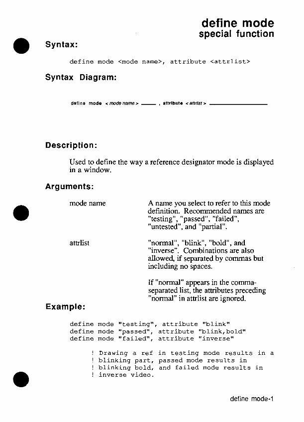
define mode
Syntax: special function
d e f i n e mode <mode name>, a t t r i b u t e < a t t r l i s t >
Syntax Diagram:
deflne mode <modename> - , attribute <atirlisr>
Description:
Used to define the way a reference designator mode is displayed in a window.
Arguments:
mode name A name you select to refer to this mode definition. Recommended names are "testing", "passed", "failed", "untested", and "partial".
attrlist "normal", "blink", "bold", and "inverse". Combinations are also allowed, if separated by commas but including no spaces.
If "normal" appears in the cornma- separated list, the attributes preceding "normal" in attrlist are ignored.
Example:
d e f i n e mode " t e s t i ng" , a t t r i b u t e "bl ink" d e f i n e mode "passed", a t t r i b u t e "b l ink ,bold" d e f i n e mode " f a i l ed" , a t t r i b u t e " inverse"
! Drawing a r e f i n t e s t i n g mode r e s u l t s i n a ! b l i n k i n g p a r t , passed mode r e s u l t s i n ! b l i n k i n g bold, and f a i l e d mode r e s u l t s i n ! i n v e r s e video.
define mode-1

define mode
Remarks:
Mode definitions are used by the draw ref command to draw the parts of a UUT and to display the status of testing for that UUT in a window on the monitor.
The modes "testing", "passed", "failed", "partial" (partially passed, not completely tested) and "untested" are the set of recommended modes. There is however no enforced restriction on mode names.
Once a TL11 invocation has started, the mode definitions are global and remain in force until explicitly removed using the remove command, or until TL/1 is restarted. TL11 is restarted whenever you press the REPEAT or EXEC keys on the operator's keypad, by pressing the INIT softkey when in the debugger, or by pressing the EXECUTE softkey when in the debugger if a program is not currently executing.
Note that each definition uses a small increment of memory. That increment is typically 10 to 30 bytes of memory for book keeping plus one byte for each character in the string or strings associated with this definition. If many mode definitions are to be made (and the program is intended to be run indefinitely), it is good practice to remove mode definitions using the remove command. This practice will prevent memory from being consumed by unused or obsolete definitions.
Related Commands:
draw, draw ref, remove
For More Information:
The "Overview of TL11" section of the Programmer's Manual.
define mode-2

define part special function
d e f i n e p a r t < p a r t name>, xdim <xs ize>, ydim <ys ize> [, xdot <h loca t ion> , ydot <vloca t ion>]
Syntax Diagram:
deflne part <partname> - . xdlm <xsize> , ydlm <yslze> ...
L , xdot < hlocafion > - , ydot < vlocation >
Description:
Used to define a part shape and size for the draw commands. Defining a part causes no action to take place on the monitor.
Arguments:
part name
xsize
y size
hlocation
vlocation
A name you select to refer to this part definition.
Horizontal size of the part to be displayed in scaled window coordinates (see the open command).
Vertical size of the part to be displayed in scaled window coordinates (see the open command).
Horizontal location of the alignment dot within the part in scaled window coordinates. If xdot and ydot are not specified, there is no dot displayed.
Vertical location of the alignment dot within the part in scaled window coordinates. If xdot and ydot are not specified, there is no dot displayed.
define part-1

define Dart
Example 1:
d e f i n e p a r t "dip" , xdim 3, ydim 10, xdot 0, ydot 0
! A p a r t name "dip" w i l l be c r e a t e d wi th ! s c a l e d window dimensions of (3,lO) and a ! dot l o c a t e d i n t h e upper le f t -hand co rne r .
Example 2:
d e f i n e p a r t "box", xdim 10, ydim 10
! A p a r t named box wi th no do t w i l l be ! c r e a t e d with s c a l e d window dimensions of ! ( 1 0 , l O ) .
Remarks:
Part definitions are used by the draw ref command to draw a UUT in a window on the monitor. To display a part, you first define its shape and size with the define part command, then you give it a reference designator name and a location with the &fine ref command, and finally draw the part on a window of the monitor with the drawref command. Doing a define part on an existing part causes the information to be replaced with the new information.
Once a TL11 invocation has started, the part definitions are global and remain in force until explicitly removed using the remove command, or until TL11 is restarted. TL11 is restarted whenever you press the REPEAT or EXEC keys on the operator's keypad, by pressing the INIT softkey when in the debugger, or by pressing the EXECUTE softkey when in the debugger if a program is not currently executing.
define part-2

define part
Note that each definition uses a small increment of memory. That increment is typically 10 to 30 bytes of memory for book keeping plus one byte for each character in the string or strings associated with this definition. If many definitions are to be made (and the program is intended to be run indefinitely), it is good practice to remove part definitions using the remove command. This practice will prevent memory from being consumed by unused or obsolete definitions.
Related Commands:
define ref, draw, draw ref, open, remove
For More Information:
"The Overview of TL/lW section of the Programmer's Manual.
define part-3
define part
define part-4
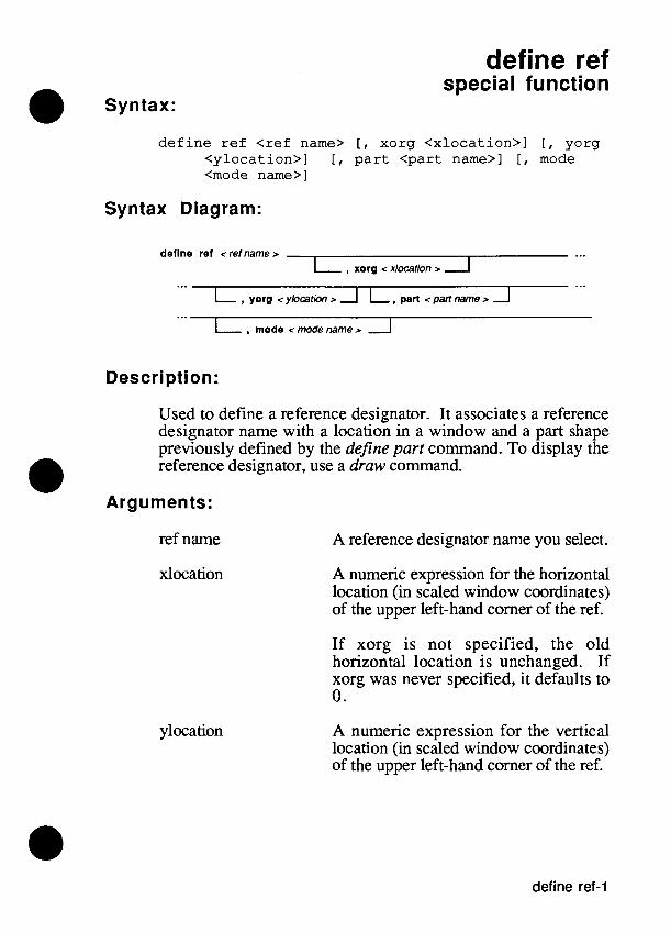
define ref
Syntax: special function
d e f i n e r e f < r e f name> [, x o r g < x l o c a t i o n > l 1, y o r g < y l o c a t i o n > ] [, p a r t < p a r t name>] [, mode <mode name>]
Syntax Diagram:
deflne ref <ref name > ... I , xorg < x~ocation > I
I , mode < mode name > 1
Description:
Used to define a reference designator. It associates a reference designator name with a location in a window and a part shape previously defined by the define part command. To display the reference designator, use a draw command.
Arguments:
ref name A reference designator name you select.
xlocation
ylocation
A numeric expression for the horizontal location (in scaled window coordinates) of the upper left-hand corner of the ref.
If xorg is not specified, the old horizontal location is unchanged. If xorg was never specified, it defaults to 0.
A numeric expression for the vertical location (in scaled window coordinates) of the upper left-hand corner of the ref.
define ref-1

define ref
If yorg is not specified, the old vertical location is unchanged. If yorg was never specified, it defaults to 0.
part name
mode name
Part name of a akjine part definition. (If not specified, the part shape is unchanged).
The name of the current display mode for the component. (If not specified, the mode is unchanged).
Example:
define ref "U3" , xorg 1, yorg 1, part "dipn, mode "untested"
! A ref defined as U3 will be at location 1,l ! drawn with the part shape and size ! specified in the part definition named ! ''dip" . The display mode will be that
! specified for untested components.
Remarks:
Reference designator definitions are used (along with define part commands) by a draw command to draw UUT components in a window on the monitor.
Once a TL/1 invocation has started, the ref definitions are global and remain in force until explicitly removed using the remove command, or until TL/1 is restarted. TW1 is restarted whenever you press the REPEAT or EXEC keys on the operator's keypad, by pressing the INIT softkey when in the debugger, or by pressing the EXECUTE softkey when in the debugger if a program is not currently executing.
Note that each definition uses a small increment of memory. That increment is typically 10 to 30 bytes of memory for book keeping plus one byte for each character in the string or strings associated with this definition. If many definitions are to be made (and the program is intended to be run indefinitely), it is good practice to remove reference designator definitions using
define ref-2

define ref
the remove command. This practice will prevent memory from being consumed by unused or obsolete definitions.
A run-time error is caused by attempting to draw a ref with no part defined or with no mode defined for the part.
Related Commands:
define part, draw, draw ref, open, remove
For More Information:
The "Overview of TL/lW section of the Programmer's Manual.
define ref3

define ref
define ref4

define text special function
Syntax:
d e f i n e t e x t < t e x t name>, l a b e l < l a b e l > , xorg <xloca t ion>, yorg <y loca t ion> [, a t t r i b u t e < a t t r l i s t > ]
Syntax Diagram:
deflne text < texTname > , label <label> ... ... , xorg < xkxatlon > , yorg <ykcation> - ...
Description:
Used to define text to be displayed in a window using the scaled location coordinates of a draw command. A piece of text is associated with attributes and a location in the window.
Arguments:
text name A string expression for the name of the text to be defined.
label The text to be displayed.
xlocation
ylocation
A numeric expression for the horizontal location (in scaled window coordinates) of the upper left-hand corner of the text.
A numeric expression for the vertical location (in scaled window coordinates) of the upper left hand comer of the text.
define text-1

define text
attrlist "normal", "blink", "bold", and "inverse". Combinations are also allowed, if separated by commas but including no spaces.
If "normal" appears in the comma- separated list, the attributes preceding "normal" in attrlist are ignored.
Example:
! Create a l a b e l named U 1 s t a r t i n g a t ! l o c a t i o n 1 0 , l O t o i d e n t i f y U 1 a s a 68000 ! c h i p . Note t h a t t h e t e x t name and r e f name ! do not need t o be t h e same. It i s done i n ! t h i s example f o r convenience.
d e f i n e t e x t " U l " , l a b e l "6800OW, xorg 1 0 , yorg 1 0 , a t t r i b u t e "bold"
Remarks:
Text definitions are used by a draw command to draw labels in a window on the monitor.
Once a TL/1 invocation has started, the text definitions are global and remain in force until explicitly removed using the remove command, or until TL/1 is restarted. TL/1 is restarted whenever you press the REPEAT or EXEC keys on the operator's keypad, by pressing the INIT softkey when in the debugger, or by pressing the EXECUTE softkey when in the debugger if a program is not currently executing.
Note that each definition uses a small increment of memory. That increment is typically 10 to 30 bytes of memory for book keeping plus one byte for each character in the string or strings associated with this definition. If many definitions are to be made (and the program is intended to be run indefinitely), it is good practice to remove reference designator definitions using the remove command. This practice will prevent memory from being consumed by unused or obsolete definitions.
define text-2

define text
Related Commands:
draw, draw ref, open, remove
For More Information:
"The Overview of TL11" section of the Programmer's Manual.
define text3

define text
define text-4

delete function
Syntax:
delete f i l e < f i l e name>
delete ( < f i l e name>)
Syntax Diagram:
delete flle <file name z
Description:
Deletes a text file from the userdisk or from a UUT directory.
Arguments: -. .
file name A string which specifies the path of the text file to be deleted. If a full pathname is not used, the text file will be deleted from the current UUT directory.
Example 1:
delete f i l e " t e s t l " ! deletes a UUT text f i l e
Example 2:
testdata = " / H ~ ~ / t e s t " delete testdata ! deletes a userdisk text f i l e
Remarks:
The delete command performs the same function as the REMOVE softkey in the editor, with the exception that the delete command removes only files of the type TEXT.

delete
Related Commands:
open, print
For More Information:
The "Overview of TLI1" section of the Programmer's Manual.

diagnoseram function +m*
Syntax:
diagnoseram addr <addr>, upto <upto>, mask <mask>, fault-addr <faultaddr>, data-expected <expdata>, data <data>
diagnoseram (<addr>, <upto>, <mask>, <faultaddr>, <expdata>, <data>
Syntax Diagram:
dlagnoseram - addr <addr> , , upto <upto> - , mask <mask> - ... ... , fault-addr < faultaddrr ...
... - , data-expected < expdata > - , data <data > -
Description:
Used with your customized RAM tests or with Pod Quick Tests to provide diagnostics and fault conditions which are consistent with those of the testramfast and testramfull RAM tests.
Arguments:
addr
upto
Starting address.
Ending address.
mask Bit mask for data bits to test.
faultaddr Address of detected fault.
expdata Data expected from fault address.
data Data actually read from fault address.
diagnoserarn-l

diagnoseram
Example:
diagnoseram addr 0, upto SFFFE, mask $7F, fault - addr $lODA, data-expected $AA, data $ ~ 8
Remarks:
The diagnoseram command is an aid for using Pod Quick tests, or for using customer-designed tests such as a downloaded RUN UUT test. The diagnoseram command supplies the same 9 lOOA/9l O5A diagnostics and fault conditions that would result from the testramfast and testramfull commands.
Related Commands:
pretestram, testrmfast, testramfull
For More Information:
The "Overview of TL11" section of the Programmer's Manual.

diagnoserom function
Syntax:
diagnoserom addr <addr>, upto <upto> [, mask <mask>], addrstep <addrstep>
diagnoserom (<addr>, <upto>, <mask>, <addrstep>)
Syntax Diagram:
dlagnoserom - addr <addr> , up10 < upto> ..,
L, m a s k < m a s k > l
... , addrstep < addrslep>
Description:
Used with your customized ROM tests or with Pod Quick Tests to preform data and address diagnostics on a range of ROM. The diagnostics and fault conditions are consistent with those of the tes6omfill ROM test.
Arguments:
addr
upto
mask
addrstep
Starting address.
Ending address.
Bit mask of valid data bits. (Default = $FFFFFFFF)
Address increment.
Example 1:
diagnoserom addr SE000, upto SEFFF, mask SFOFO, addrstep 2

diagnoserom
Example 2:
diagnoserom addr a d s t a r t , up to ( a d s t a r t + SOFFF), add r s t ep 1
Remarks:
The diagnoserom command is similar to testromfull in functionality and results. The major difference is testromfull performs both a test of the ROM (by comparing the ROM signature with an expected signature), and diagnostics if the signatures do not match. The diagnoserom command does not test the ROM (so it does not require a valid ROM signature) and goes right into the diagnostics.
Another difference with diagnoserom is it tests for address line faults first, while testromfull tests for data line faults first. If there are both address faults and data faults, the two tests will report different results.
The diagnoserom command is intended for use with your customized ROM tests, or when a Pod Quick Test indicates that the ROM signature is incorrect.
Related Commands:
For More Information:
The "Overview of TL/lW section of the Programmer's Manual .
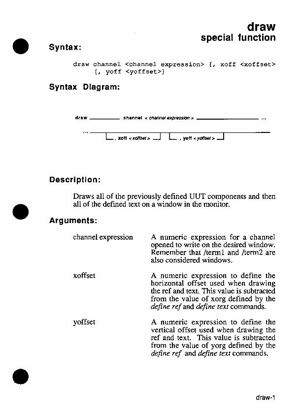
draw
Syntax: special function
draw channel <channel express ion> [, xoff <xof f se t> [, yof f <yof f s e t > ]
Syntax Diagram:
draw channel < channel expressim r ...
Description:
Draws all of the previously defined UUT components and then all of the defined text on a window in the monitor.
Arguments:
channel expression A numeric expression for a channel opened to write on the desired window. Remember that /term1 and /term2 are also considered windows.
xoffset
yoffset
A numeric expression to define the horizontal offset used when drawing the ref and text. This value is subtracted from the value of xorg defined by the define ref and define text commands.
A numeric expression to define the vertical offset used when drawing the ref and text. This value is subtracted from the value of yorg defined by the define ref and define text commands.

draw
Example:
draw channel ch3
! Display a l l d e f i n e d UUT components and a l l ! d e f i n e d t e x t on t h e window opened f o r ! w r i t i n g through a channel named ch3.
Related Commands:
define mode, define part, define ref, define text, open
For More Information:
The "Overview of TL/l" section of the Programmer's Manual.

draw ref special function
Syntax:
draw r e f <list of r e f s > , channel <channel express ion>, [, xof f <xof f set>] [, yof f <yof f s e t > ]
Syntax Diagram:
draw ref <list of refs r , channel < channel expressbn r ...
Description:
Draw previously defined UUT components on a window in the monitor. This command can also be used to change the display mode of a component or list of components.
Arguments:
list of refs A list of reference designators defined by define ref commands. When more than one reference designator is included in the list, the reference designators are separated by commas (but no spaces are used). If this argument is an empty string, all defined refs are drawn.
channel expression A numeric expression to define a channel opened to write on the desired window. Remember that /term1 and /term2 are also considered windows.
draw ref-1

draw ref
xoffset
yoffset
A numeric expression to define the horizontal offset used when drawing the ref. This value is subtracted from the value of xorg defined by the define ref command.
A numeric expression to define the vertical offset used when drawing the ref. This value is subtracted from the value of yorg defined by the define ref command.
Example:
draw r e f "U3, US, U22, U l " , channel ch2 ! Display t h e s p e c i f i e d group of UUT ! components on a window w r i t t e n t o by a ! channel named ch2
Related Commands:
define mode, define part, define ref, draw, open
For More Information:
"The Overview of TLI1" section of the Programmer's Manual.
draw ref-2
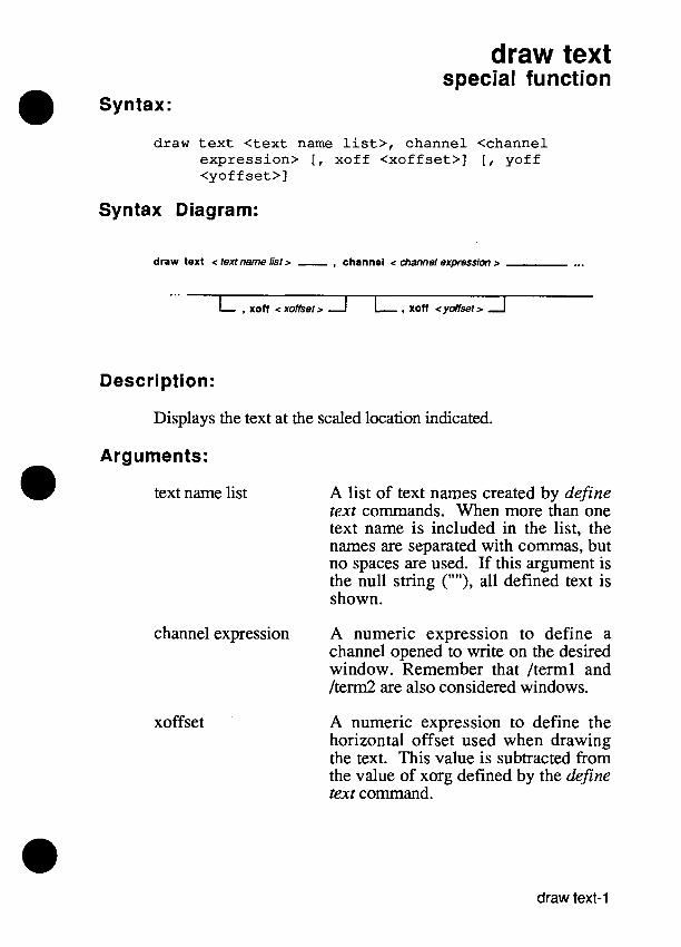
draw text special function
Syntax:
draw t e x t < t e x t name l i s t> , channel <channel exp re s s ion> [, xoff < x o f f s e t > ] [ , yoff <yof f s e t > ]
Syntax Diagram:
draw text c text name list > - , channel c &annel expression > ... ...
L , xoii c x o ~ e t > A I, , xoii c y ~ s e t > 1
Description:
Displays the text at the scaled location indicated.
Arguments:
text name list
channel expression
xoffset
A list of text names created by define text commands. When more than one text name is included in the list, the names are separated with commas, but no spaces are used. If this argument is the null string (""), all defined text is shown.
A numeric expression to define a channel opened to write on the desired window. Remember that /term1 and /term2 are also considered windows.
A numeric expression to define the horizontal offset used when drawing the text. This value is subtracted from the value of xorg defined by the define text command.
draw text-1

draw text
yoffset A numeric expression to define the vertical offset used when drawing the text. This value is subtracted from the value of yorg defined by the define text command.
Example 1:
draw t e x t " labl , lab2", channel chanl ! draw only lab1 and lab2 on a window opened ! f o r wri t ing through a channel named chanl
Example 2:
draw t e x t "", channel chanl ! draw a l l def ined t e x t on a window opened ! f o r wri t ing through a channel named chanl
Related Commands:
define text, draw, open
For More Information:
The "Overview of TL/l" section of the Programmer's Manual.
draw text9

edge function
Syntax:
edge [device <device l i s t > ] [, s t a r t < s t a r t edge>] [, s t o p < s t o p c o n d i t i o n > ] [ , c lock <clock edge>]
edge (<device l i s t> , < s t a r t edge>, < s t o p condi t ion>, <clock edge>)
Syntax Diagram:
devlce < devim list> start -Z start edge >
clock < clock edge >
Description:
Specifies the active edge of the external START, STOP, and CLOCK lines for the probe or an VO module. Allowable edges are rising ("+") or falling ("-"); "count" is also allowed for the stop condition.
Arguments:
device list
start edge
I/O module name, clip module name, probe name, or combinations of these. (Default = "/probe")
VO module external start edge "+", "-", or "at-arm". (Default = "+")

edge
Probe external start edge "+" or "-". (Default = "+")
stop condition External stop edge "+" or "-", or "count" condition (value determined by the TL/1 stopcount function). (Default = "+")
clock edge External clock edge "+" or "-". (Default = "+")
Example:
mod = c l i p ref " ~ 5 4 " ~ pins 1 6 edge device mod, start "+" , stop clock "+"
Related Commands:
a m , readout, stopcount
For More Information:
The "Overview of TL/1" section of the Programmer's Manual.
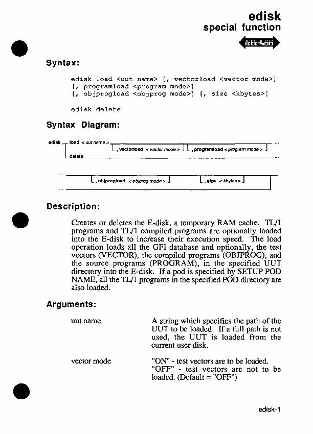
special function
Syntax:
edisk load <uut name> [, vectorload <vector mode>] [, programload <program mode>] [, objprogload <objprog mode>] [, s i ze <kbytes>l
edisk de le te
Syntax Diagram:
edisk load < uut name >
T ...
1 , vectorload < vector mode > 1 L , programload <program mode > J delete ...
... L , oblprogload < objpmg moder J 1 , alzo < kbytes > 1
Description:
Creates or deletes the E-disk, a temporary RAM cache. TL/1 programs and TL11 compiled programs are optionally loaded into the E-disk to increase their execution speed. The load operation loads all the GFI database and optionally, the test vectors (VECTOR), the compiled programs (OBJPROG), and the source programs (PROGRAM), in the specified UUT directory into the E-disk. If a pod is specified by SETUP POD NAME, all the TL11 programs in the specified POD directory are also loaded.
Arguments:
uut name A string which specifies the path of the UUT to be loaded. If a full path is not used, the UUT is loaded from the current user disk.
vector mode "ON - test vectors are to be loaded. "OFF" - test vectors are not to be loaded. (Default = "OFF")

edisk
program mode " O N - programs (PROGRAM) are to be loaded. "OFF" - programs are not to be loaded. (Default = "ON)
objprog mode " O N - compiled programs (OBJPROG) are to be loaded. "OFF" - compiled programs are not to be loaded. (Default = "ON")
kbytes Size of the E-disk in kilobytes. (Default = 500K bytes)
Example 1:
! create an E - d i s k of s i z e 1 0 0 0 k b y t e s and ! load it f r o m u s e r d i s k DR1 , u u t DEMO, ! i n c l u d i n g t h e test vectors, PROGRAMS, and ! O B J P R O G s
e d i s k load m/DR1/DEMO", vectorload "ON" , s i z e 1 0 0 0
Example 2:
! create an E - d i s k of s i z e 5 0 0 k b y t e s and load ! it f r o m u s e r d i s k HDR, u u t T K 8 0 w i t h o u t t h e ! test vectors, w i t h o u t PROGRAMS, bu t ! i n c l u d i n g O B J P R O G s .
e d i s k load " / H D R / t k 8 O W , p r o g r a m l o a d "OFF"
Example 3:
! delete t h e E - d i s k
e d i s k delete

edisk
Remarks:
To delete the E-disk, use the delete form of the E-disk function. The E-disk is also automatically deleted when the EDIT key is pressed on the 9100A. Either procedure releases the previously allocated E-disk memory for use with other operations.
To create the E-disk, you must ascertain that sufficient memory is available in RAM. Once the E-disk is created, you may also have to adjust RAM allocations so that there is enough left for other functions. Insufficient RAM before and after the creation of the E-disk results in error messages. Adjustments to RAM to create a balance of available memory are made with the kbytes argument.
To adjust the size of the E-disk, reduce the number of kbytes until an error message no longer occurs. Another way to make memory available is to turn off VECTORS, PROGRAMS, or OB JPROGs.
If an E-disk currently exists when this statement is issued, one of the following occurs:
If the UUT directory name of the current E-disk does not match the specified UUT directory name, the original files are deleted and the new files loaded. If the UUT directory name of the current E-disk matches the newly specified UUT directory, a merge copy takes place.

edisk

enable function
Syntax:
enab le [device <device l i s t > ] [, mode <mode name>]
enab le (<device l i s t> , <mode name>)
enab le ( )
Syntax Diagram:
dovlce < devicelist> mode <modename>
Description:
Sets the enable mode of the response gathering hardware for the probe or an 110 module. Used only when the sync mode is ffext".
Arguments:
device list I/O module name, clip module name, probe name, or combinations of these. (Default = "/probe")
mode name I/O module enable modes: "always", "high", "low", or "pod".
Probe enable modes: "always", "high", "low", "pod", "pod*enOW, "pod*en 1 ". (Default = "always")
Example 1:
mod = c l i p r e f "U22", p i n s 28 enab le device mod, mode "high"
enable
Example 2:
enable device "/probew, mode "pod"
Remarks:
The enable mode is one of the following:
"high"
"low"
"always"
"pod"
"pod*enOn
"pod*en 1 "
Enable condition is true when the external enable line is high.
Enable condition is true when the external enable line is low.
Enable condition is always true.
Enable condition is generated by the pod sync pulse.
Enable condition is generated by the pod sync pulse ANDed with the enable signal. The enable condition is true if the pod's PodSync line is active and the clock module enable line is low. This mode is valid only for the probe.
Enable condition is generated by the pod sync pulse ANDed with the enable signal. The enable condition is true if the pod's PodSync line is active and the clock module enable line is high. This mode is valid only for the probe.
Related Commands:
arm, readout, sync
For More Information:
The "Overview of TL/lW section of the Programmer's Manual.

end statement
end end end end end end end end end end end
d e c l a r e e x e r c i s e < f a u l t cond i t i on> f u n c t i o n < func t ion name> handle < f a u l t cond i t i on> i f loop program <program name>
Syntax Diagram:
end
c fault condition > 6 Ir--I c program name >
Description:
Defines the end of a block.
Arguments:
fault con& tion
function name
The fault condition used to call an exerciser block or a handler block.
The function name used to call the function block.

end
program name The program name used to call the program block.
Examples:
end d e c l a r e ! ends a v a r i a b l e d e c l a r a t i o n block
end i f ! ends an i f . . . t hen o r an ! i f . . . t hen . . . else ! block
end loop ! ends a loop block
end my-exer ! ends an e x e r c i s e r block, where t h e ! f a u l t name g iven i n t h e ! e x e r c i s e s ta tement i s my-exer
end my-func ! ends a func t ion , where t h e func t ion ! name given i n t h e func t ion ! s ta tement i s my-func
end my-hand1 ! ends a f au l t -hand le r block, where ! t h e f a u l t name ! given i n t h e handle s ta tement ! i s my-hand1
end m y s r o g ! ends a program, where t h e program ! name g iven i n t h e program s ta tement ! is m y g r o g
Related Commands:
declare (block form), exercise, function, handle, if, loop, program
For More Information:
The "Overview of TL/ln section of the Programmer's Manual.

endif statement
Syntax:
endif
Syntax Diagram:
Description:
Specifies the end of an if block.
Example:
if a < 4 then b = O c = l
endif
Remarks:
In TL11 endif is functionally equivalent to end i f . This form of the end i f statement is provided for ANSI compatibility, but is not the recommended W 1 syntax.
Related Commands:
if, end
For More Information:
The "Overview of TL/1" section of the Programmer's Manual.

endif

execute statement
Syntax:
[execute] <name> <argname> <argvalue> { , <argname> <argvalue> )
[execute] <name> (<argvalue> { , <argvalue>))
[execute] <name> ( )
Syntax Diagram:
I
L execute J < argname > - < argva~ue > A A -
Description:
Causes the named program or function to be executed. The execute keyword is optional.
Arguments:
name Valid program or function name.
argname Name of an argument.
argvalue An expression which provides the value for an argument.
Example 1:
! Suppose you have written a function called ! send which requires two arguments: ! addr and data. This is an example of ! calling send using keyword notation.
execute send addr a, data d

execute
Example 2:
! This i s equivalent t o Example 1, but t h e ! argument l i s t i s wr i t t en i n p o s i t i o n a l ! no ta t ion .
execute send (a , d)
Example 3:
program test4 funct ion f l ! def ines t h e funct ion •’1
c h l = open device "/term2", a s "output" p r i n t on c h l "Executed funct ion f l " c l o s e channel ch l
end f 1
execute f l 0 ! c a l l s t h e funct ion f l
execute •’1 ( ) ! c a l l s t h e funct ion f l
execute t e s t 3 ( 1 ! c a l l s another program ! s ince t h i s name i s not ! def ined a s a funct ion i n ! t h i s program
end program
Remarks:
The argument list for the execute command has two forms:
Keyword notation - where argument name and argument value pairs are listed with each pair separated by commas.

execute
Positional notation - where only the argument values are listed in order separated by commas. The order of argument values must be the same as the order in the program or function command called by the execute command.
The value returned by a function may be used as the argument to another function, as in the statement z = f(g(x),y). When the functions use keyword notation, it may be difficult to interpret the resulting statement. In the following invocation:
z = f f-argl g g-argl x, arg2 y
it is not obvious whether arg2 belongs to g's argument list or f s argument list. Therefore, when a function invocation using keyword notation is an argument to another function, the argument function invocation must be surrounded by parentheses to remove ambiguity as shown in the following:
Related Commands:
function, program, return
For More Information:
The "Overview of TL11" section of the Programmer's Manual.

execute
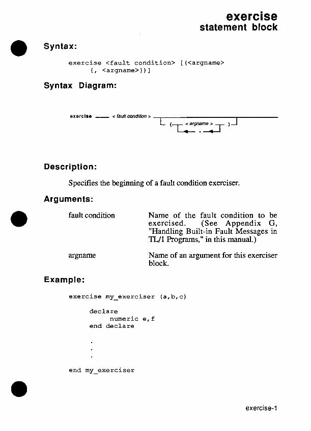
exercise statement block
Syntax:
exercise <fault condition> [(<argname> { , <argname>) ) 1
Syntax Diagram:
Description:
Specifies the beginning of a fault condition exerciser.
Arguments:
fault condition Name of the fault condition to be exercised. (See Appendix G , "Handling Built-in Fault Messages in TL11 Programs," in this manual.)
Name of an argument for this exerciser block.
Example:
exercise my-exerciser (a,b,c)
declare numeric e,f
end declare
end my-exerciser

exercise
Remarks:
A fault condition exerciser is a sequence of statements that detects a particular, previously discovered fault condition. When a fault condition occurs, an operator can execute the exerciser continually (controlled through the operator's display) while attempting to repair the UUT fault. A program or function can provide exercisers for fault conditions that are raised during execution.
You may write your own exercisers in TL/1 or use the built-in exercisers provided by the built-in tests.
The fault name must be the same in both the exercise command and the end command. A fault exerciser has the name of the fault condition it is intended to exercise.
The argument list consists of argument names separated by commas. If any arguments have default values, these values are assigned in the declarations. The exercise command must include all arguments named in the corresponding faul t command, but it can include additional arguments as well.
Unlike the scope of a variable name, which is static based upon the block structure of a TL/1 program, the scope of an exerciser is dynamic. The scope of an exerciser extends from the time at which the containing block is entered until the containing block is exited. If the block invokes another function, the exerciser remains "active", unless another exerciser with the same name is activated in the invoked block.
Variables declared inside an exerciser are local unless explicitly declared to be global.
Any fault condition that is exercised causes the program to indicate that the UUT fails if the last full iteration of the exerciser detected a fault and allows the program to indicate a "passes" if the last full iteration of the exerciser did not detect a fault.

exercise
Related Commands:
declare, end, execute, fails, handle, passes, refault, return
For More Information:
The "Overview of TL/1" section of the Programmer's Manual.

exercise

fabs function
Syntax:
f a b s num <expression>
f abs (<express ion>)
Syntax Diagram:
tabs n urn < expression r
Description:
Returns the absolute value (floating-point) of the argument value.
Arguments:
expression The floating-point argument value.
Returns:
A floating-point value.
Examples:
f = f a b s ( f ) ! Convert f t o i t s a b s o l u t e ! va lue .
f = f a b s num ( s i n ang le f )
Remarks:
If fabs returns

fabs
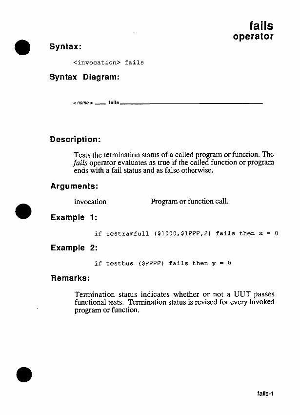
Syntax:
fails operator
<invocation> fails
Syntax Diagram:
<name D - falls
Description:
Tests the termination status of a called program or function. The fails operator evaluates as true if the called function or program ends with a fail status and as false otherwise.
Arguments:
invocation
Example 1:
Program or function call.
if testramfull ($1000,$1FFF,2) fails then x = 0
Example 2:
if testbus ($FFFF) fails then y = 0
Remarks:
Termination status indicates whether or not a UUT passes functional tests. Termination status is revised for every invoked program or function.

fails
Termination status can be:
passes represents completion of a test without any unhandled fault conditions. The UUT is free from any faults that the test can detect.
fails represents the existence of one or more unrepaired faults at the end of test execution.
A program that runs to completion without detecting any faults indicates that the UUT passes. Detection of a fault by the program (or any programs it calls) affects the termination status of the program. Any unhandled, unexercised fault condition causes the program to indicate that the UUT fails. Any fault condition that is exercised causes the program to indicate that the UUT fails if the last full iteration of the exerciser detected a fault and allows the program to indicate a "passes" if the last full iteration of the exerciser did not detect a fault. The termination status of a program is accumulated in the program that called it, so that if any called programs indicated a failure, the calling program also indicates that the UUT fails.
A fault condition can be handled by a block of statements called a fault condition handler. The fault condition handler has access to the arguments of the fault and the global variables of the test program. When a fault condition handler encounters either a return statement or its last statement the handler terminates, and execution resumes at the statement following the fault command
If the handler does not execute a fault command, the fault condition is handled and disappears. In this case, the termi- nation status is "passes".
A fault command with no fault name or arguments unconditionally sets the termination status to "fails."
When a refault or a fault command with a fault name is executed, the termination status is affected by the presence of other handlers or exercisers for the fault condition.

fails
Related Commands:
execute, exercise, fault, handle, i f , passes, refault, while
For More Information:
The "Overview of TL/l" section of the Programmer's Manual.

fails

fault statement
Syntax:
fault [<fault condition> <argname> <argvalue> { , <argname> <argvalue>) 1
Syntax Diagram:
fault L < fault condition >
< argname r - < argvalue r - A 1 -
Description:
Raises a fault condition and provides a list of arguments that describe details of the fault condition.
Arguments:
fault condition Name of the fault condition to be raised.
argname Name of an argument.
argvalue An expression which provides the value for an argument.
Example 1:
if errors > 10 then fault ! termination status ! is set to "fails"
Example 2:
fault pod-data-tied mask mask, access-attempted "write", addr adr2, data d

fault
Remarks:
A fault condition occurs during execution when the UUT does not respond as expected. When faulty UUT behavior is detected by a test program, a fault condition describing the behavior is raised with a fault command. The fault command consists of a fault name and a list of arguments that describe details of the fault condition.
When a fault command is executed, program execution is suspended. If the current invocation contains a handler for the raised fault condition, the handler is executed. If the current invocation does not contain a handler for the raised fault condition, each invocation in the calling chain is checked until a handler is found. If no invocation has a handler for the raised fault condition, the system issues the fault message on the operator's display.
A program that runs to completion without detecting any faults indicates that the UUT passes. Detection of a fault by the program (or any programs it calls) affects the termination status of the program. Any unhandled, unexercised fault condition causes the program to indicate that the UUT fails. Any fault condition that is exercised causes the program to indicate that the UUT fails if the last full iteration of the exerciser detected a fault and allows the program to indicate a "passes" if the last full iteration of the exerciser did not detect a fault. The termination status of a program is accumulated in the program that called it, so that if any called programs indicated a failure, the calling program also indicates that the UUT fails.
A fault condition can be handled by a block of statements called a fault condition handler. The fault condition handler has access to the arguments of the fault and the global variables of the test program. When a fault condition handler encounters either a return statement or its last statement the handler terminates, and execution resumes at the statement following the fault command.
If the handler does not execute a fault command, the fault condition is handled and disappears. In this case, the terrni- nation status is "passes".

fault
A fault command with no fault name or arguments unconditionally sets the termination status to "fails."
When a refault or a fault command with a fault name is executed, the termination status is affected by the presence of other handlers or exercisers for the fault condition.
Related Commands:
execute, exercise, fault, handle, if, passes, refault, while
For More Information:
The "Overview of TL/l" section of the Programmer's Manual. Appendix H, "Raising Built-in Fault Messages in TL/1 Programs," in this manual.

fault

f ilestat function
Syntax:
f i l e s t a t f i l e < f i l e name s t r i n g >
f i l e s t a t ( < f i l e name s t r i n g > )
Syntax Diagram:
fllostat fllr < file name string >
Description:
Returns information about the existence, readability, and writeability of a text file.
Arguments:
file A string containing a relative or absolute file path name.
Returns:
A three character string if the file exists, or the empty string if the file does not exist.
The first character of the string is "r" if the file is readable and "-" otherwise.
The second character of the string is "w" if the file is writable and is "-" otherwise.
The third character of the string is "-".

filestat
Example:
The example prints "DEMO--rw-" if the text file DEMO in the current UUT exists and is not write protected.
Remarks:
Filestat returns information about the status of the file. It cannot tell if a floppy disk write-protect tab is in the protected position.
Related Commands:
cwd, open, close
For More Information:
The "Overview of TL/1" section of the Programmer's Manual.

for statement block
for <variable> = <expression 1, to <expression 2> [step <expression 3>]
Syntax Diagram:
for - < variable > = < expression 1 > to < expression 2 > . . .
Description:
Executes a series of statements repeatedly for each value of a control variable within a specified range.
0 Arguments: variable Any numeric variable; used as an index.
expression 1 An integer expression for the lowest value in the range.
expression 2 An integer expression for the highest value in the range.
expression 3 An integer expression which specifies the increment after each loop iteration. (Default = 1)

for
Example:
f o r n = 1 t o 5 s t e p 2
! i f n i s 5 o r less, perform ! t h e s t a t emen t s w i th in t h e ! " fo r " b lock . Since t h e ! "s tep" v a r i a b l e i s 2 , t h e ! s t a t emen t s wi th in t h e ! block a r e executed t h r e e ! t i m e s .
next
Remarks:
The for . . . next block repeats the controlled statements for each value of an index variable within a specified range, after which execution continues at the line following the end of the block. The for . . . next block ends with a next statement.
The optional step expression indicates how much to add to the block control variable after each iteration of the block.
The f o r . . . next block is provided for ANSI compatibility, but the recommended TL/l structure is the loop for . . . end loop block.
Related Commands:
loop, next
For More Information:
The "Overview of TL/l" section of the Programmer's Manual.

fstr function
Syntax:
f s t r num <expression>
f s t r (<expression>)
Syntax Diagram:
fstr nu m c expression z
Description:
Produces a string representation of the floating argument value.
Arguments:
expression A floating-point argument value.
Returns:
The default string representation of the floating argument value.
Examples:
s = "The answer is" + f s t r ( f ) s = f s t r num f
Remarks:
The returned string is in scientific format, with six digits of precision following the decimal point. For example, the following are strings produced by the fstr command:

fstr
Related Commands:
fvar
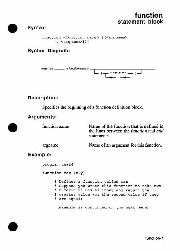
function statement block
Syntax:
f u n c t i o n < func t ion name> [(<argname> { , <argname> ) ) ]
Syntax Diagram:
lunctlon - <function name r ( TI a r g y r
Description:
Specifies the beginning of a function definition block.
Arguments:
function name Name of the function that is defined in the lines between the function and end statements.
argname Name of an argument for this function.
Example:
program tes t4
f u n c t i o n max (x, y )
! Defines a f u n c t i o n c a l l e d max ! Suppose you wrote t h i s func t ion t o t a k e two ! numeric va lues a s i npu t and r e t u r n t h e ! g r e a t e r va lue ( o r t h e second va lue i f t hey ! a r e e q u a l ) .
(example i s cont inued on t h e next page)

function
d e c l a r e numeric x numeric y
end d e c l a r e i f (x>y) t hen
r e t u r n x else
r e t u r n y end i f
end max
a = max ( 1 6 , da tawid th) ! c a l l s t h e f u n c t i o n max ! d e f i n e d a t t h e beginning ! of t h e program
end program
Remarks:
A function is a sequence of TL/1 statements called by a single name. A function is syntactically identical to a program except that it begins with a function statement rather than a program statement.
The only difference between the program and function definition block is that the scope of a function name extends only within the block (usually a program block) that encloses it. The scope of a program name is every program in the same UUT and every program in the program library.
The function name used in the function statement, the end statement, and all invocations of the function must be the same. Function names are case-sensitive; "add" is not the same as "aDd." A function name cannot be the same as the name of a built-in function.
The argument list consists of one or more argument names separated by commas. The list is enclosed in parentheses. The order of the names in this list is the same order in which the values for these arguments must be listed in positional notation calls to this function. If any arguments have default values, these values are assigned in the subsequent declaration blocks.

function
Function arguments may not be declared as arrays, nor as global or persistent variables.
Function definition blocks may contain any or all of the following: declaration blocks, handler definition blocks, and exerciser definition blocks.
Related Commands:
declare, end, execute, exercise, handle, program, return
For More Information:
The "Overview of TL/lM section of the Programmer's Manual.

function

fval function
Syntax:
fval str <expression>
fval (<expression>)
Syntax Diagram:
fval str < expression >
Description:
Calculates the floating-point value of the string argument.
Argument:
expression A valid string expression which represents a floating-point number.
Returns:
The floating-point value obtained by interpreting the string.
Examples:
f = fval ("1.0") ! f is set to the value 1.0
f = fval str "-3E2" ! f is set to the value ! -300.0
f = fval ("2") ! f is set to the value 2.0 ! Note that a decimal point ! is not necessary here.

fval
Remarks:
Any string which can be interpreted as a decimal floating-point number is acceptable. Decimal points are not required. In addition, the first character of the string can be a minus sign, indicating that the number is negative.
Related Commands:
fstr, isflt

getoffset function
Syntax:
getoffset [device <device name>] [, pin <pin number>]
getoffset (<device name>, <pin number>)
getof f set ( )
Syntax Diagram:
getoffset d e v 1 c e < device name z I p l n < pin number z
Description:
Returns the current calibration delay offset for the specified device. The value returned is biased by 1000000 (decimal). This value can be changed via calibration, restoring caldata, or using the setoffset command. Each sync mode (such as pod addr, pod data, or ext) has a separate offset associated with it. Thus, changing sync modes also changes the offset.
Arguments:
device name VO module name or probe name. (Default = "/probew)
pin number (Default = 1)
Returns:
The current calibration delay offset for the specified device.

getoffset
Example 1:
! This example looks at the current offset for ! external sync in the probe
sync device "/probew, mode "ext" offset = getoffset device "/probew
Example 2:
! This example looks at the current offset for ! pod address sync in 1/0 module 2
sync device "/mod2", mode "pod" sync device "/podm, mode "addr" offset = getoffset device "/mod2"
Remarks:
The getoffset command is valid only when the sync mode is "pod" or "ext".
The value returned is biased by 1000000 (decimal). This means that a returned value of 1000000 represents an offset of 0 nanoseconds, a returned value of 1000020 represents an offset of 20 nanoseconds, and a returned value of 999970 represents an offset of -30 nanoseconds.
The offset value can be changed by calibration, by restoring caldata, or by using the setoffset command. In addition, each sync mode (such as pod addr, pod data, or ext) has a separate offset associated with it. Thus, changing sync modes also changes the offset.
The getoffset function will not necessarily return exactly the same value that setoffset passed. This is because the hardware delay line provides delay increments of about 15 nanoseconds.

getoffset
Related Commands:
For More Information:
The "Overview of TL11" section of the Programmer's Manual. The "Offset Command" section of the Programmer's Manual for information on using offsets with GFI.

getoffset

getpod function
Syntax:
getpod podname
Syntax Diagram:
Description:
Returns information about the current pod.
Arguments:
podname Return the name of the currently connected pod.
Returns:
The name of the current pod.
Example:
i f i n s t r ( (getpod podname), "M") = 1 then p r i n t "9132A pod i n use"
end i f
Remarks:
There is a current pod name ( called "32BIT") when no pod is plugged in. 9132A pod names all begin with "M", so getpod is useful to determine the type of pod.
Related Commands:
podinfo, podsetup

getpod
For More Information:
The "Overview of TLI1" section of the Programmer's Manual.

getromsig function 4 j *
Syntax:
getromsig addr <address I>, upto <address 2> [, mask <mask>], addrstep <addrstep>
getromsig (<address I>, <address 2>, <mask>, addrstep>)
Syntax Diagram:
... , addrstep < addrstep > , mask <mask>
Description:
Returns the signature gathered from one or more ROMs using a mask to select which data bits will be used to form the signature.
Arguments:
address 1 Starting address.
address 2 Ending address.
mask Bit mask of data bits to be used to form the signature. (Default = $FFFFFFFF)
addrstep Address increment.
Returns:
The signature measured.

getromsig
Example 1:
measured-sig = getromsig addr 0, upto $7FF, addrstep 2
Example 2:
measured-sig = getromsig (first, last, $7C, 4)
Remarks:
The ROM signature is a CRC word calculated from the data contained in the ROM. The ROM data is considered to be composed of bit streams consisting of data bit k of addresses (addr, addr + addrstep, addr + 2*addrstep; addr + 3*addrestep, etc.). These bit streams are concatenated with the most significant set bit in mask first, followed by less significant set bits, with the CRC result being taken from the concatenated bit stream. Therefore, if mask has only one set bit, the CRC returned by getromsig is the same as the signature that would be returned if the probe were placed on the same data bit, and reads were done at addresses (addr, addr + addrstep, addr + 2*addrstep, addr + 3"addrstep etc.).
Related Commands:
For More Information:
The "Overview of TL/l" section of the Programmer's Manual. Supplemental Pod Information for 91 00Al91 O5A Users Manual. The Fluke pod manual for the microprocessor you are using.

getspace function -
Syntax:
getspace <argname> <argvalue> { <argname> <argvalue>)
getspace (<argvalue> I , <argvalue>))
Syntax Diagram:
getspace < argname r , < argvalue r 1 A - -
Description:
Converts a list of specified address parameter values to a number suitable as an argument for the setspace command. This number depends on the specified parameter values and on the pod which is currently connected.
Arguments:
argname
argvalue
Returns:
Address parameter name (refer to the Supplemental Pod Information for 9100A/9105A Users Manual for the microprocessor you are using).
The address parameter string value you select (refer to Supplemental Pod Information for 91 00AI91 O5A Users Manual for the microprocessor you are using).
The selected address space as a number.

getspace
Example:
program test 6 s = getspace space "memory", size "word"
! an 80286 address space setspace space s
end program
Remarks:
Microprocessor address lines usually have multiple addressing modes. These are often referred to as address spaces. For example, in the Z80 microprocessor, two address spaces are available: memory space and 1/0 space. More powerful microprocessors have a correspondingly larger number of address spaces that can be used. When testing a microprocessor-based UUT, you must select an address space and any other addressing parameters that are needed to test the UUT in the desired address space.
The 9100A19105A provides a convenient means to select the address space and other addressing parameters. When a pod is connected to the 9100A/9105A and the power is turned on (or the RESET key is pressed), the addressing parameters possible for this pod are made available to the 9100A/9105A in the form of a list of strings representing all legal combinations of addressing options. These options are shown on the operator's display when appropriate commands are selected from the operator's keypad.
These options are also selectable by TU1 through the use of the getspace function used along with the setspace command. With the getspace function, you specify both a name and a selected string value for each address parameter. No parameters may be left out. The getspace function then checks the list of address parameter combinations and returns a number related to the position in the list where the specified combination was found. The Supplemental Pod Information for 91 OOA/9I 05A Users Manual shows the appropriate parameter names and all legal combinations of parameter values that can be used for each supported microprocessor.

getspace
For example, when you refer to The Supplemental Pod Information for 9IOOA/9105A Users Manual, you would find the information on the 80186 microprocessor to write the following getspace command. (A summary of this information for the 80186 microprocessor is also shown in Appendix I of this manual.)
s = getspace mode "normal", space "memory", s i z e g lw~rdg '
This command would request the number of the address parameter string which has "normal" as the choice for the mode parameter, "memory" as the choice for the space parameter, and "word" as the choice for the size parameter.
The number returned by getspace is then used with the setspace command to set the pod to operate with the requested addressing parameters. For example, you might use the following command to set the pod to use the number returned by the getspace command above:
s e t s p a c e space s
Related Commands:
setspace, sysspace
For More Information:
The "Overview of TL/l" section of the Programmer's Manual. Appendix I, "Pod-Related Information," in this manual.
The Supplemental Pod Information for 91 OOA/91 O5A Users Manual. The Fluke pod manual for the microprocessor you are using.

getspace

gfi special function
Syntax:
g f i g f i g f i gf i g f i g f i g f i g f i g f i g f i g f i g f i gf i gf i
accuse a u t o s t a r t < a u t o s t a r t mode> c l e a r c o n t r o l dev i ce f a i l < r e f p i n name> f a i l < r e f name> h i n t < r e f p i n name> pas s < r e f p i n name> p a s s < r e f name> r e f s t a t u s < r e f p i n name> sugges t test < r e f p i n name> [, autoprompt <autoprompt
s t a t e > ]
Syntax Diagram:
control device
c rebin name r c ref name r
hint c mfpin name r
c rewn name r c ref name r
ref status - c re/pin name r suggest test - c dpin name r
, autoprompt c autoprompt state r
Description:
The gfi commands allow TL/1 to interact with the resident GFI software. The gfi status and gfi test commands can be used as the heart of functional testing using the probe and VO module. Using these commands to perform functional tests has the advantage of using the learned responses (response files) which characterize the known-good UUT rather than including response information in TL/1 functional test programs.

gfi
Options:
accuse
autostart
clear
(Has no argument value.)
This option returns a string that describes the current GFI accusation, or conclusion ("Ul is BAD or OUTPUT U1-24 is LOADED", for example). If GFI currently has no accusations, an empty string is returned.
This option enables or disables an automatic transition from a TL11 functional test to GFI.
The autostart mode can be "enable" or "disable". If the mode is "enable", GFI automatically starts after a TL/1 program that generates GFI hints has finished running. If the mode is "disable", a message is displayed informing the operator that GFI hints are available.
(Has no argument value.)
This option erases the GFI summary and GFI suggestion list. It also forces the UUT's GFI database out of memory. An empty string is returned. An error will be reported if a stimulus program attempts to clear GFI. This command should be executed before troubleshooting of a new UUT is begun.

gfi
control
device
fail
(Has no argument value.)
This option determines whether the program is being executed under GFI control. A value of "yes" or "no" is returned.
(Has no argument value.)
This option returns a string containing the name of the measurement device ("/probe", "/mod 1 ", "/mod2", "/mod3", "/mod4", etc.) that is being used. Typically, the device list returned is passed to other TL/1 functions which accept device lists and affect the 110 module and probe.
This option is used only in stimulus programs, which are executed under control of the GFI program. If the program is not being executed under GFI control, an error is reported.
aefpin name>
This option is used in a GFI stimulus program to force GFI to fail the specified pin, independent of the actual measured response.
The FAIL applies only to the single program that this statement appears in.
The specified pin must be a pin that is currently being tested by GFI. The name of the current pin or ref being tested can be obtained using the 'gfi ref option.

gfi
a-ef name>
hint
pass
If a reference designator name is specified, it will force GFI to fail all the pins on that ref that are tested by the stimulus program.
This option adds the specxied pin name to the end of the GFI suggestion list. This option is used in functional tests to identify nodes that are suspected to be faulty.
a-efpin name>
This option is used in a GFI stimulus program to force GFI to pass the specified pin, independent of the actual measured response.
The PASS applies only to the single program that this statement appears in. (If a pin is tested by several stimulus programs, the cumulative status of the pin can still be BAD if the pin fails one or more of those other programs).
The specified pin must be a pin that is currently being tested by GFI. The name of the current pin or ref being tested can be obtained using the 'gfi ref option.
a e f name>
If a reference designator name is specified, it will force GFI to pass all the pins on that ref that are tested by the stimulus program.

gfi
ref (Has no argument value.)
status
suggest
test
This option returns a string containing the name of the reference designator or pin that is being tested by GFI.
This option is used only in stimulus programs, which are executed under control of the GFI program. If the program is not being executed under GFI control, an error is reported.
This options returns a string describing the status of the named pin. It returns: "good" if the pin has been tested and was good, "bad" if the pin has been tested and was bad, and "untested" if the pin has not been tested or no such pin exists.
(Has no argument value.)
This option returns a string containing the first (highest priority) suggestion on the GFI suggestion list. The string has the form "ref-pin". If the suggestion list is empty, an empty string is returned.
<refpin name>, [autoprompt <au topromp t state>]
This option tests the named pin by executing all stimulus programs associated with it. If the named pin is tested with the VO module, GFI will test all the pins on the component.

gfi
The TL/1 "passes" or "fails" condition will be set according to the status of the component (not just the named pin). It will be set to "fails" if any pin on the component is bad. It will be set to "passes" if all the pins on the component are good or untested:
The autoprompt state can be "yes" or "no". (Default = "yes".) If it is "yes", then the necessary operator prompts to clip or probe the component will be automatically generated. If it is "no", the system assumes that the programmer has already prompted the operator. Prompting for the UO module must be done with the TL/1 clip command. This function updates the system connection data for the module, which is used by GFI.
This option cannot be used in a GFI stimulus program.
Example 1:
! This program performs t h e equ iva l en t of RUN G F I ! from t h e o p e r a t o r ' s keypad and d i s p l a y . The only ! d i f f e r e n c e i s t h a t no g raph ic s w i l l be gene ra t ed ! f o r t h e p a r t .
program auto-gfi loop whi le ( ( ( g f i accuse) = "") and
( ( g f i sugges t ) <> " " ) ) p i n = g f i sugges t g f i test p i n
end loop end auto-gf i

gfi
Example 2:
g f i a u t o s t a r t "enable" g f i h i n t "U25-15"
! enab le a u t o s t a r t and add U25-15 t o t h e G F I ! sugges t ion l i s t
Example 3:
! tes t a l l p i n s on U l ( i f U 1 i s t e s t e d with ! t h e 1/0 module)
i f g f i tes t " U l - 1 " pa s se s t hen p r i n t " U 1 i s good"
else p r i n t "U1 i s badw p r i n t " U l - 1 i s ", ( g f i s t a t u s " U l - 1 " ) p r i n t "Ul-2 i s ", ( g f i s t a t u s "Ul-2") p r i n t "Ul-3 i s ", ( g f i s t a t u s "Ul-3")
end i f
Example 4:
! This s t imu lus r o u t i n e wiggles t h e d a t a p i n s out ! t o t h e i n p u t s of a l l components d i r e c t l y ! connected t o t h e microprocessor bus b u f f e r .
program micro-data
! I f t e s t i n g wi th GFI t hen I g e t dev i ce name from G F I
! else not t e s t i n g wi th GFI I s o s p e c i f y device name
i f ( g f i c o n t r o l ) = "yes" t hen d e v l i s t = g f i dev ice
else d e v l i s t = w/modlm
end i f

gfi
! Setup measurement and ! stimulus devices.
x = getspace space "memory", size "word" setspace (x)
! Reset device to known state ! then configure devices as desired
reset device devlist sync device devlist, mode "pod" sync device "/podw, mode "data" threshold device devlist, mode "ttl" counter device devlist, mode "transition" arm device devlist ! Begin measurement
! Perform stimulus to UUT rampdata addr $20000, rampdata addr $20000, rampdata addr $20000, rampdata addr $20000,
readout device devlist !
data 0,mask $1F data 0,mask $IF0 data 0,mask $IF00 data 0,mask $IF000 End measurement
end micro-data
Remarks:
The gfi accuse, gfi suggest, and gfi test commands can be combined to perform the equivalent RUN GFI from the operator's keypad and display (see example 1). You can also drive an autoprober by modifying example 1; position the autoprober before performing the gfi test command.
The gfi test and gfi status commands can be used as the heart of functional testing. Once the UUT has been divided into sections, functional test programs can be written for each section. These functional tests can use the gfi test command to test the components generating output signals for each section.
For example, assume a section has two ICs, U21 and U33, that provide the output signals for that section. In this case, gfi test "U21-1" and gfi test "U33-1" can be used to test these two components and therefore, the output of the section. (There is an additional assumption that the VO module is being used to test
gfi
U21 and U33. When the 110 module is used, gfi test will test all pins on the IC, not just the specified pin.) If one or more of the gfi test commands fails, the gfi status command can be used to find out which pins on the components failed. The failing pins can be entered in the suggestion list using the gfi hint command.
Stimulus programs can be executed from the operator's keypad and display, from the debugger, and from GFI. The gfi control command and gfi device command are used to identify when GFI is running, and if it is, to get the testing device from GFI (see example 4).
Refer to the Programmer's Manual for a description of the GFI program and information on how to create a UUT database for GFI.
For More Information:
The "Overview of TL11" section of the Programmer's Manual. The "Guided Fault Isolation (GFI)" section of the Programmer's Manual.

gfi

got0 statement
Syntax Diagram:
goto < label r
Description:
Causes program execution to jump to the beginning of the line labeled by <label>.
The goto command should be avoided where possible (see the Remarks section for this command).
Arguments:
label A statement label which exists in the program. A label is always followed by a colon (": ").
Example:
program test7
if y <> 24 then goto finish ! skips the lines ! from here to
a = a + l ! the label b = b + l ! finish unless y c = c + l ! is equal to finish: ! decimal 24
end program

Remarks:
Normal execution of statements in a program proceeds in order from one statement to the following statement. But the goto command causes program execution to jump to the line with the specified label.
In the preceding example, if y is not equal to 24, the statements between the ifcommand and the label "finish" are not executed, the goto command transfers program execution to the line beginning with thefinish label.
No more than one line can be labelled with a particular name. Labels must meet the requirements for variable names as outlined in Section 2 of this manual, "Name Conventions." A colon separates the label from the rest of the line, but is not part of the label name.
The goto command should be avoided where possible; it is provided as a last-choice alternative to other control statements. A more orderly and logical flow of instructions can be achieved by using loop . . . end loop blocks and if. . . end if blocks.
Several restrictions and caveats apply to the goto command:
The label specified by a goto command must mark an executable command line somewhere in the current definition block (program, function, handler, or exerciser). A goto command cannot jump from one definition block to another or from a program into an enclosed definition block.
A goto command cannot jump to a line contained in a loop for . . . end loop block.
A goto command cannot jump out of a loop for . . . end loop block.

Related Commands:
if, loop
For More Information:
The "Overview of TL/1" section of the Programmer's Manual.


haltuut function
Syntax:
h a l t u u t ( )
Syntax Diagram:
Description:
Terminates normal runuut operation, if it is active, and displays any fault conditions that occurred during the runuut execution.
Example:
h a l t u u t ( 1
Remarks:
After executing runuut, you must invoke either haltuut or waituut to regain control of the pod before executing other statements that send commands to the pod. A haltuut command is equivalent to waituut (0).
Related Commands:
runuut, waituut
For More Information:
The "Overview of TLI1" section of the Programmer's Manual.

haltuut

handle
Syntax: statement block
handle < f a u l t cond i t i on> [(<argname> , <argname> ) ) ]
Syntax Diagram:
Description:
Specifies the beginning of a fault condition handler block.
Arguments:
fault condition Name of the fault condition to be handled. (See Appendix G, "Handling Built-in Fault Messages in TL/1 Programs," in this manual for a list of built-in fault messages.)
argname Name of an argument for this handler block.
Example:
handle my-handler ( a , b, c )
end my-handler ! o r t h i s l i n e cou ld be simply end handle

handle
Remarks:
A fault condition handler is a sequence of statements which is executed when a fault condition occurs. Fault condition handlers localize the statements that deal with or respond to the occurrence of a particular fault condition; without handlers, these same statements would require duplication anywhere the fault condition could occur (in some cases, almost anywhere in a program). Handlers are used to acknowledge the presence of fault conditions, inspect data about fault conditions, and make decisions regarding fault conditions. A program or function can provide handlers for fault conditions that may be raised during execution. When a handler exists for a raised fault condition, the normal execution of the program is temporarily suspended and the handler is invoked.
You may write your own handlers in TL11 for any fault conditions raised by built-in tests or Wl fault commands.
The fault name must be the same in both the handle statement and the end statement. A fault handler has the name of the fault condition it is intended to handle.
The argument list consists of argument names separated by commas. If any arguments have default values, these values are assigned in the declarations. The handle statement must include all arguments named in the corresponding fault command, but it can include additional arguments as well.
Unlike the scope of a variable name, which is static based upon the block structure of a TL/1 program, the scope of a handler is dynamic. The scope of a handler extends fiom the time at which the containing block is entered until the containing block is exited. If the block invokes another function, the handler remains "active."

handle
Variables declared inside a handler are local unless explicitly declared to be global.
When a fault condition handler encounters either a return statement or its last statement the handler terminates, and execution resumes at the statement following the fault command. If the handler does not execute a fault command, the fault condition is handled and disappears. In this case, the termination status is "passes".
Related Commands:
abort, declare, end, execute, exercise, fails, fault, passes, re$ault, return
For More Information:
The "Overview of TL/lM section of the Programmer's Manual. Appendix G , "Handling Built-in Fault Messages in TL/1 Programs," in this manual.

handle

special function Syntax:
ieee channel <channel> [ , t imeout <t imeout i n t e r v a l > ] [ , s t a t u s < s t a t u s b y t e va lue> I [ , e o i < e o i a s s e r t i o n f l a g > I [ , message < i n t e r f a c e message> I
Syntax Diagram: Iwe channel < channel r . . .
. . . . . . , theout < timeout interval r
. . . *talus c stat- byte value r
, ool < eoi assertion /lag r I . . .
, mowage < intertam message r
Description:
When the 9100A/9105A is configured as an IEEE-488 talkerfiistener, the ieee command is used to:
Setlclear the most significant bit of the serial poll status byte.
When the 9100419105A is configured as an IEEE-488 controller, the ieee command is used to:
Issue IFC (Interface Clear).
Send DCL (Device Clear) to all bus devices or SDC (Selected Device Clear) to all devices in a group. Assert REN (Remote Enable), optionally addressing a group of devices to listen, putting them in Remote State. De-assert REN.
Send GTL (Go To Local) to a group of devices to put them in Local State.
Send GET (Group Execute Trigger) to a group of devices to trigger them.

ieee
For both configurations of the 9100A/9105A, the ieee command is used to:
set the EOI Enable flag associated with an IEEE-488 channel, controlling EOI assertion on the last output byte of any print command on the channel. set the timeout interval associated with a channel.
If an UO error occurs while attempting to process an ieee command (for example, a timeout error occurs), then the io-error fault is raised, with numeric argument err-num containing the error number and string argument err-msg. For example, the following is a TL11 code fragment for an io-error fault handler:
handle io-error (err-num, err-msg) declare numeric err-num declare string err-msg print using "Error ?# : ? # l l , err-num, err-msg
end handle
Some of the operations described below are susceptible to termination by timeout, while others are not. The former are explicitly noted as being susceptible to timeout. If no mention is made of timeout susceptibility, the operation is not susceptible. When a timeout error occurs, the io-error fault is raised with the ercnum and err-msg fault arguments set to indicate a timeout.
Arguments:
channel A mandatory numeric argument, which must be a channel number returned by the open command. The channel will optionally have an IEEE-488 address list associated with it. (See the description of the open function for details.) If so, the channel is said to be open on a group of bus devices. If not, the channel is said to be open on the IEEE-488 interface.

ieee
status
message
An optional numeric argument, which specifies the timeout interval to use for any IEEE-488 bus operation on this channel, in milliseconds. A value of zero specifies an infinite timeout interval; i.e., tirneouts are disabled.
An optional numeric argument, which specifies the value to assign to the serial poll status byte. Only the most significant bit (bit 7) can be set from TLI1. If bit 7 is setlcleared in this argument, bit 7 in the serial poll status byte is seth1eare-d. All other bits in the argument are ignored.
This argument is applicable only when the 9100Al9105A is configured as a talkerllistener. If it is configured as a controller, the status argument is ignored.
An optional string argument, which specifies whether EOI (End or Identify) assertion on the last output byte of any print command on this channel is enabled (the argument value is "on") or disabled (the argument value is "off'). The argument value is case-insensitive.
Even if last byte EOI assertion is disabled, EOI is still asserted on any termination character associated with the channel when it was opened (see the open command, described in this manual for details).
An optional string argument, which specfies a special-purpose interface message or operation. This argument is only applicable if the 9100A/9105A is configured as a controller; if it is configured as a talkerllistener, use of this argument causes an error.

ieee
The message argument takes one of the following values. These are interpreted case-insensitively:
ifc
clear
local
remote
The IFC line (Interface Clear) is momentarily asserted for at least 100 microseconds.
If the channel is opened on the IEEE- 488 interface, UNT (Untalk), UNL (Unlisten), and DCL (Device Clear) are issued.
If the channel is opened on a group of devices, UNT and UNL are issued first, then each device in the group is addressed to listen, then SDC (Selected Device Clear) is issued.
Both forms of this operation are susceptible to tirneout.
If the channel is opened on the IEEE- 488 interface, REN (Remote Enable) is de-asserted.
If the channel is opened on a group of devices, UNT and UNL are issued first, then each device in the group is addressed to listen, then GTL (Go To Local) is issued.
Only the latter form of this operation is susceptible to tirneout.
First, REN is asserted. If the channel is opened on a group of devices, UNT and UNL are issued and each device in the group is addressed to listen.
If the latter step is performed, this operation is susceptible to tirneout.

ieee
trigger If the channel is opened on a group of devices, first UNT and UNL are issued, then each device in the group is addressed to listen, then GET (Group Execute Trigger) is issued.
This operation is susceptible to timeout.
If more than one of the optional arguments are supplied, they all take effect in the following order: eoi, timeout, status, and message. If none of the optional arguments are supplied, the ieee command does nothing.
The default initial values for a channel are zero for timeout and off for eoi. The default initial value for the serial poll status byte is the current value of the byte; that is, changes to the serial poll status byte survive the execution of a TLJ1 program.
Example 1:
These examples illustrate operation as a talker~listener.
The following TLJ1 fragment sets, then clears, bit 7 in the serial poll status byte:
ieee-chan = open device "/ieeem ieee channel ieee-chan, status $80 ieee channel ieee-chan, status 0
The following W 1 fragment opens the IEEE-488 interface with the termination character set to "nothing", then prints a single record to the interface with three separate print using commands. EOI assertion is disabled for the first two print using commands, and turned on for the last one; as a result, EOI is asserted on the last byte of the last print using command.
ieee-chan = open device "/ieeeW, term "" ieee channel ieee-chan, eoi "off" print on ieee-chan, using "?#", vl print on ieee-chan, using "?#" , v2 ieee channel ieee-chan, eoi "on" print on ieee-chan, using "?#" , v3

ieee
The following TU1 fragment opens the IEEE-488 interface with the termination character set to linefeed, then perpetually inputs a single line from the interface and echoes it back:
declare string s ieee-chan = open device "/ieeeW, term "\OAW loop
input on ieee-chan, s print on ieee-chan, s
end loop
Example 2:
These examples illustrate operation as a controller.
The following TL11 fragment momentarily asserts IFC for at least 100 microseconds:
ieee-chan = open device "/ieeeW ieee channel ieee-chan, message "ifc"
The following TL11 fragments illustrate the two uses of the "clear" message. The first one sends DCL to all devices on the bus, while the second one sends SDC to a particular group of devices:
! send DCL ieee-chan = open device "/ieeeW ieee channel ieee-chan, message "clear"
! send SDC to addresses 2, 3, and 4:10 ! (primary address 4, secondary address 10) ieee-chan = open device "/ieee/2,3,4:10m ieee channel ieee-chan, message "clear"
The following TLI1 fragment asserts REN:
ieee-chan = open device "/ieeeW ieee channel ieee-chan, message "remote"
The following TL11 function sends a hypothetical voltmeter a command requesting a measurement, inputs the measurement, strips the measurement of whitespace, verifies that the measurement string represents a floating-point value, and returns

ieee
the value. If any I/O errors which result in the io-error fault occur, they are handled locally.
Note that with this fragment a global variable is used to flag whether I/O failed. In an application that uses this function, the caller would examine this flag before attempting to use the return value from get-rdg for anything. Also, note that the io-error handler doesn't do much about the 110 error. In a real application, the I/O error handling would be more sophisticated, and have provision for retries, clearing the IEEE-488 bus, etc.
function get-rdg
handle io-error (err-num, err-msg) declare numeric err-num ! 1/0 error number string err-msg ! 1/0 error message
global numeric term-chan ! terminal channel global numeric io-failed ! 1/0 failed flag end declare
io-failed=l print on term-chan, using "Error ? # : ?#", err-num, err-msg
end handle
declare global numeric io-failed global numeric term-chan numeric d x c h a n st ring dv-eas-string
end declare
io-failed = 0 ! clear the "I/O failed" flag term-chan = open device "/terml" ! open the error message channel
! open a channel to the DVM, which has IEEE-488 ! address 1, ! using a linefeed character as the terminator d x c h a n = open device "/ieee/lW, term "\OA1' if (io-failed) then return (0.0)

ieee
! set the timeout on the DVM channel to 4 ! seconds ieee channel dxchan, timeout 4000 if (io-failed) then return (0.0)
! send the reading request to the DVM print on dxchan, "rdg?" if (io - failed) then return (0.0)
! input the measurement string input on dxchan, dv-eas string if (io - failed) then return (0 .O)
! this hypothetical DVM terminates readings with a ! carriage return, linefeed combination. The ! linefeed will have been removed, since it was ! specified as the termination character; however, ! dvm-meas-string will still have the carriage ! return. Strip it and any other whitespace via ! the 'tokenv function. dv-eas-string = token str dv-eas-string, from 1 ! verify that the measurement string is a ! floating-point number if (isflt (dv-eas-string) ) then return (fval (d~m-meas~string) )
else io-failed = 1 return (0.0)
end if
end function
Related Commands:
open, print, input, poll
For More Information:
The "IEEE-488, 9100A-015" section of the Technical User's Manual". The "9100 Series Error Numbers" appendix in this manual.

if (block form) statement block
Syntax:
i f <condi t ion> then
Syntax Diagram:
If - c condition z - then
Description:
Specifies the beginning of an if block.
Arguments:
condition A logical expression.
Example 1:
! i f t h e v a r i a b l e " i n i t i a l i z e d " has t h e ! va lue 0, t hen . . .
i f no t i n i t i a l i z e d then i = O s t a r t = 0 s t o p = 255 i n c r = address-increment
end i f
Example 2:
i f b 0 t hen i f a / b > 10 then ! b i g t e s t i s executed
execute b i g t e s t ! only i f bo th b <> 0 ! and a / b > 10
end i f end i f
if (block form)-1

if (block form)
Example 3:
! if the value of the variable "lower" is ! less than the value of the variable ! "upper", then perform the program/ ! function "rangetest", using "lower" and ! "upper" as arguments.
if ( lower <= upper ) then range-test (lower , upper)
! else perform the program/function ! "range-error" using "lower" and "upper" ! as arguments.
else range-error (lower , upper)
end if
Example 4:
if lbit < 4 then b = O
else if lbit = 4 then b = l
else if lbit = 5 then b = 2
else ! (if lbit > 5 then) b = 3
end if
Remarks:
An if block executes a list of statement lines if a condition in the if statement is true (non-zero). If the condition is true, execution begins on the line immediately following the if statement. When the controlled statements have been completed, execution continues at the line following the end if statement.
If the condition is false, the condition of the first else i f statement (if one exists) is evaluated, if the condition is true, the statements controlled by the else if block are executed, then execution continues at the line after the end i f statement. I f the condition of the else i f statement is false, the condition of each following else i f statement is evaluated in the same way.

if (block form)
If the condition of the if statement and all of the else if statements are false, the statements controlled by the else block (if one exists) are executed. If no else block exists, execution continues at the statement following the end if.
NOTE
You may nest if statements within other i f statements. TLII does not limit the number of i f levels used.
Related Commands:
end, if (statement form)
For More Information:
The "Conditional Expressions" section in Section 2 of this manual. The "Overview of TL11" section of the Programmer's Manual.
if (block form) -3

if (block form)
if (block form)-4

Syntax:
if (statement form) statement
i f <condi t ion> then <statement l i s t>
Syntax Diagram:
I f - c condition > - then < stalemenl lisl>
Description:
Executes statement(s) under control of a condition.
Arguments:
condition A logical expression.
statement list One or more W1 statements, separated by backslashes fi), all appearing on one line.
Example 1:
i f x = 10 then a = a + 1
Example 2:
i f x = l O t h e n a = a + l \ b = b + l
Example 3:
i f x = 10 then a = a + 1 \ i f a = 11 then b = 3
if (statement form)-1
if (statement form)
Remarks:
A single-line if statement controls only the statements which appear on a single line. The statements on the line are executed if the condition is true; after the controlled statements have been executed, execution continues on the following line. If the condition is false, the controlled statements are not executed.
An if statement may appear within another if statement. In this case, execution continues throughout the entire statement line, until either the last statement on the line is executed, or one of the conditions evaluates to false.
You may structure conditions so that under certain circumstances they are not fully evaluated. For example, in the statement:
if (b <> 0) and (a/b > 10) t h e n x=l
the second condition must not be evaluated when b is equal to zero, because it would cause a divide-by-zero error. To avoid the potential error, you write:
if (b <> 0) t h e n if (a/b > 10) t h e n x=l
The first if statement controls all statements to its right. If the first condition is false, the second condition is not evaluated.
Related commands:
i f (block form)
For More Information:
The "Conditional Expressions" section in Section 2 of this manual. The "Overview of TL/lW section of the Programmer's Manual.
if (statement form)-2

input statement
Syntax:
i n p u t [on <channel>,] < v a r i a b l e l i s t>
Syntax Diagram:
Input , c variable list z L on cchannelz, 1
Description:
Reads data from the text file, serial port, keyboard, or other interface associated with a specified channel, and stores it into specified variables. The input command waits for characters to be input.
Arguments: - channel A numeric expression that identifies a
device open for input. (Default = the first channel opened for "input" or "update")
variable list List of variables in which to store input data values.
Example 1:
i npu t on ichan, a , b, c ! reads i n t h r e e va lues from device on k h a n ! when en t e r ed , t h e s e va lues must be s e p a r a t e d ! by space c h a r a c t e r s

Example 2:
input startaddr, endaddr, addrincr ! reads in three values from ! operator's keypad ! provided a channel has been opened
Remarks:
Before using the input statement, the input variables must be declared and the input device must be opened for input. The input statement performs the following actions:
Suspends program execution until data appears on the specified channel. Reads data from the specified channel.
Stores the data in the specified variables.
If the channel is buffered, the input statement reads data from the channel until it encounters the channel's termination character, which usually defaults to a new-line character (OD hexadecimal on most keyboards, the ENTER key on the operator's keypad). If the channel is not buffered, the input statement suspends execution until it reads a single character (any key code).
Space characters must be used to separate multiple input values entered with an input command.
To input hexadecimal numeric data, use the input using command.

input
If an 110 error occurs while attempting to process an input command (for example, a timeout error while attempting to input from an IEEE-488 device), the 'io-error' fault is raised, with numeric argument 'err-num" containing the 9 1 OON9 1 O5A error number and smng argument ' e r~msg ' containing a description of the error. For example, the following is a TL/1 code fragment for an io-error fault handler:
handle io-error (err-num, err-msg) declare numeric err-num declare string err-msg print using "Error ? # : ?#", err-num, err-msg
end handle
If the input is obtained from a channel opened on either the IEEE-488 interface or a device connected to the IEEE-488 interface, then buffered input can be terminated by either the termination character associated with the channel or by the assertion of EOI on the last input character. If input is terminated by EOI assertion and the associated character is not the termination character, then that character is included in the input value.
Related Commands:
input using, open, print, poll, ieee
For More Information:
The "Overview of TLI1" section of the Programmer's Manual. The "Operator's Keypad Mapping to TL/1 Input," appendix in this manual. The "Programmer's Keyboard Mapping to TL/1 Input," appendix in this manual. The"9 100A/9 lO5A Error Numbers" appendix in this manual. The "IEEE-488, 9 100A-015" section of the Technical User's Manual".


input using statement
Syntax:
input using <format string> [, on <channel>], <variable list>
Syntax Diagram:
input using cformatstringz , c variable list z - L , on cdrannelz J
Description:
Reads data from a specified channel, compares it with an expected format, and stores it in specified variables.
0 Arguments:
format string
channel
variable list
The string that defines the input format. ("buffered mode only.)
A numeric expression that identifies a device open for input. (Default = the first channel opened for "input" or "update".)
List of variables in which to store input data values.
Example 1:
input using "TITLE: # # # # # # # WR.PROT: ###",t,wp
! the input data: ! TITLE: prog 1 WR.PROT: YES ! produces the values: ! t = "prog 1 ", wp = "YES"
input using-1

input using
Example 2:
i n p u t u s i n g "& @ % #", a , b, c, d ! The i n p u t d a t a : ! 1 2 3 4 ! p r o d u c e s t h e v a l u e s : ! a = l , b = 2 , c = 3 , d 5 4 ! The f o l l o w i n g i n p u t d a t a p r o d u c e s a n e r r o r : ! 4 3 2 1 ! b e c a u s e "4" i s n o t ma tched b y t h e " & " ! p i c t u r e , which e x p e c t s o n l y "1" o r "0"
Example 3:
i n p u t u s i n g " : # # # % # % # % # % # % # % # % # % # % # % " , a d d r , a , b , c, d, e, f , g , h , chksum
! The i n p u t d a t a : ! :100000010203040506078F ! p r o d u c e s t h e v a l u e s ! a d d r = 1000, a = 0, b = 1, c = 2, ! d = 3 , e = 4 , f = 5 , g = 6 , h = 7 , ! chksum = 8F
Example 4:
i n p u t u s i n g " ? & ? @ ? % ? # ?^", a , b, c, d, f
! The i n p u t d a t a : ! 0101 100 100 32 1 .97 ! p r o d u c e s t h e d e c i m a l v a l u e s ! a = 5, b = 100, c = 256 ! d = 32, f = ( f l o a t i n g ) 1 .97 ! The i n p u t d a t a : ! 011 2 5 11 9999 2.OE30 ! p r o d u c e s t h e d e c i m a l v a l u e s ! a = 3, b = 25, c = 17, ! d = 9999, f = ( f l o a t i n g ) 2.OE+30
input using-2

input using
@ Example 5:
/
input using " # # ^ ^ ^ ###^^EEEEE", •’1, f2
! The input data: ! 3.2 32.33+100 ! produces the floating-point values ! •’1 = 3.2, •’2 = 3.233+101
Remarks:
The input using statement requires that the input variables be previously declared and that the input device has already opened for input. The input using statement performs the following actions:
Suspends program execution until data appears on the specified channel. Reads data from the specified channel.
Stores the data in the specified variables.
If an VO error occurs while attempting to process an input using command (for example, a timeout error while attempting to input from an IEEE-488 device), then the io-error fault is raised, with numeric argument err-num containing the 9 lOOA/9 lO5A error number and string argument err-msg containing a description of the error. For example, the following is a TL/1 code fragment for an io-error fault handler:
handle io-error (err-num, err-msg) declare numeric err-num declare string err-msg print using "Error ? # : ?#", err-num, err-msg
end handle
input using-3

input using
If the input is obtained from a channel opened on either the IEEE-488 interface or a device connected to the IEEE-488 interface, buffered input can be terminated by either the termination character associated with the channel or by the assertion of EOI on the last input character. If input is terminated by EOI assertion and the associated character is not the termination character, then that character is included in the input value.
The input using statement is an extended form of the input statement which uses format specifications which are provided in format strings. Through format specifications, you can set the expected number of characters of digits for each data value, and the radix (hexadecimal, decimal, or binary) for numeric data. You can also specify other data that must appear in the input but is not actually required for storage into variables. An error occurs when the number of input values does not match the number of format pictures in the format specification.
A format string contains zero or more format pictures. A format picture is a string that describes the format for a single data value. Format pictures are one of two types: fixed-width and variable-width. Fixed-width format pictures match each input character with a format picture character, while variable-width format pictures match as many input characters as possible in the context of the data type for the format picture.
input using-4

input using
Fixed-width Formatted Input
A fixed-width format picture consists of zero or more "#" characters (floating digit places), followed by one or more "%", tt@tt, It&tt, tt#tl, or ttAtt characters (fixed digit places,) which also describe the radix. The format picture characters are defined below:
Symbol Description
# A floating digit or character place. If this symbol is in the right-most place in a numeric input format picture, the input is interpreted in decimal radix. Otherwise, this symbol is interpreted as a floating digit, matching digit, or a space. For string input, this symbol matches with any character.
Required digit place for hexadecimal numbers. This symbol, and any "#" symbols to its left matches with a hexadecimal digit.
Required digit place for decimal numbers. This symbol, and any "#" symbols to its left matches with a decimal digit.
Required digit place for binary numbers. This character and any "#" symbols to its left matches with a binary digit.
Required digit place for floating-point numbers. A sequence of """ characters may optionally be followed by a fixed sequence of five "E" characters. For output format pictures, this represents the exponent field; here, it is provided merely for symmetry with output format pictures.
input using5

input using
If the value is to contain more than one digit or character, the picture must be extended to the left by "#" characters, one for each additional digit or character. For example, the picture "@ " represents a single-digit decimal number; the picture "###@" represents a four-digit decimal number. The picture "#######" represents a seven-character suing or a seven-digit decimal number. The picture "%%%%" represents a four-digit hexadecimal number with required leading zeros (OOFF).
If numbers in the input smng are not separated by non-numeric characters, one of the required digit characters must appear as the last character of the format picture. The two format pictures, "####" and "###@", when combined, yield a format picture, "#######@", which is interpreted as an eight-digit decimal picture, not two four-digit pictures. If two pictures are needed, use a space ("#### ####"), use the fixed digit characters ("###Yo###%"), or use two consecutive input statements.
Fixed-width input format checking for floating-point numbers is less smct then it is for other data types. The number of input characters implied by the width of the format pictures are collected and checked to make sure that they represent a valid smng representation of a floating-point number.
Variable-Width Formatted Input
Like a fixed-width format picture, a variable-width format picture describes the format for a single data value. The difference is that a variable-width format picture accepts as many input characters as it can use to match the picture's data type. A variable-width format picture consists of a single "?" character, followed by a single character denoting the picture type. The following special picture type characters are defined:
# Match a variable-width string or decimal number.
% Match a variable-width hexadecimal number.
@ Match a variable-width decimal number.
input using-6

input using
& Match a variable-width binary number.
A Match a variable-width floating-point number
? Match a single "?" character.
If the picture type character is not one of the above, then the format picture means "match one or more of the literal character". For example, the input picturen?X" will match one or more "Xu characters in the input. For variable-width literal character matches, no assignment to input variables is performed.
Note that it is not possible to match a variable number of "?" characters; that is, the picture "??" implies a match of exactly one "?" character.
Related Commands:
input, open, print using
For More Information:
The "Overview of TL/lM section of the Programmer's Manual. Appendix J "9100A/9105A Error Numbers".
The"9100A/9105A Error Numbers" appendix in this manual. The "IEEE-488, 9100A-015" section of the Technical User> Manual".
input using-7

input using
input using-8
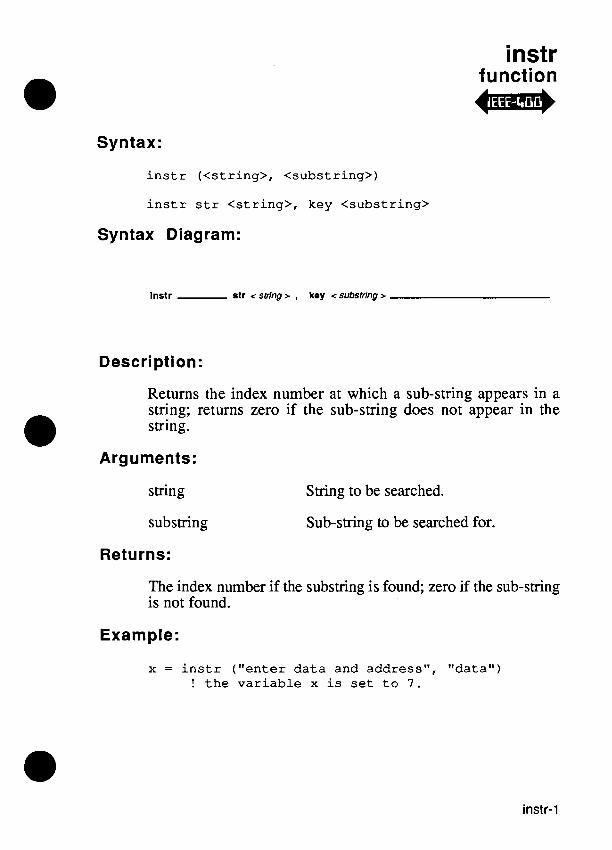
instr function
Syntax:
i n s t r ( < s t r i n g > , < s u b s t r i n g > )
i n s t r s tr < s t r i n g > , key < s u b s t r i n g >
Syntax Diagram:
lns t r e t r < string z , key < substring >
Description:
Returns the index number at which a sub-string appears in a string; returns zero if the sub-string does not appear in the string.
Arguments:
string String to be searched.
subsmng Sub-string to be searched for.
Returns:
The index number if the substring is found; zero if the sub-smng is not found.
Example:
x = i n s t r ( " e n t e r d a t a and address" , " d a t a " ) ! t h e v a r i a b l e x i s set t o 7 .

instr
Remarks:
An index number is the number corresponding to a particular character position within a character string. For example, the index of "r" in "America" is 4.

isflt function
Syntax:
isflt str <expression>
isflt (<expression>)
Syntax Diagram:
Description:
The isflt command is used to pre-test an expression for validity as an argument to thefval co&and.
Arguments:
expression The string expression that is to be tested.
Returns:
1 if the expression is a valid argument to fval, implying thatfval will not report an error with the expression as its argument
0 if the expression is not a valid argument tofval
Examples:
isflt ("~oo") isflt ("1.0")
! returns 0 ! returns 1

isflt
Remarks:
The isflt command is particularly useful for strings obtained by the input command, which may be expected to be strings representing valid floating-point numbers, but are not guaranteed to be.
Related Commands:
fval, isval, token

isval function
Syntax:
isval str <expression> [ , radix <radix> ] isval (<expression>, <radix>)
Syntax Diagram:
lsval slr <expression >
,radix <radix>
Description:
The isval command is used to pre-test a set of arguments for validity as arguments to the val command.
radix
The string expression which is to be tested for representation of a valid number in the indicated radix.
A numeric expression for the radix of the interpreted number. Allowable values for radix are 2, 8, 10 (default), and 16.
Returns:
1 if the arguments are a valid set to val (implying that val will not report an error with the given argument set).
0 if the arguments are not a valid argument set to val.

isval
Remarks:
The isval command is useful for strings obtained by the input command, which may be expected to be strings representing valid numbers, but are not guaranteed to be.
Examples:
isval ("f 00") ! returns 0 isval ("l", 2 ) ! returns 1 isval ("3", 2 ) ! returns 0 isval ("3", 10) ! returns 1
Related Commands:
val, isflt, token

Syntax:
len operator
l e n < s t r i n g >
Syntax Diagram:
len c string r
Description:
Counts the number of characters in the string operand.
Arguments:
string String or string expression whose length is to be determined.
Returns:
The number of characters in the string.
Example 1:
x = l e n "I/O f i n i shed" ! t h e v a r i a b l e x is ! s e t t o C (hex)
Example 2:
a = "Hello" x = l e n a ! t h e v a r i a b l e x is
! s e t t o 5

len

level function
Syntax:
l e v e l [device <device name>] [, p i n <p in number>] [, t ype < type name>] [, r e f p i n < r e f p i n name>]
l e v e l (<device name>, <pin number>, < type name>, < r e f p i n name>)
l e v e l ( )
Syntax Diagram:
devlce < devicenamew
p l n < pin number w type < type name w
Description:
Returns the synchronous level history or asynchronous level history for one pin. The data can be requested either in terms of an 110 module pin, a component pin, or the probe. This command will return useful information only after an arm . . . readout block has taken a measurement.
Arguments:
device name
pin number
type name
I/O module name, clip module name, probe name, or reference designator. (Default = "/probew)
Pin number. (Default = 1)
"clocked" or "async". (Default = "clocked)

level
refpin name Specify the device and pin in string format. The refpin argument is used to override the device and pin values. (Default = "")
Returns:
A number that represents the level history:
0 - No levels clocked. 1 - Low. 2 - Invalid. 3 - Invalid, low. 4 - High. 5 - High, low. 6 - High, invalid. 7 - High, invalid, low.
Example 1:
mod = c l i p ref "u3", pins 40
arm device mod execute s t i m g r o g loop while ( (checkstatus (mod) <> SF) ) end loop
readout device mod
modlevel = l e v e l device "u3", pin 3, type "clocked"
Example 2:
arm device "/probew
readout device "/probew probelevel = l e v e l device "/probew, type "clocked"

level
Remarks:
The level function returns the synchronous level history or asynchronous level history for one pin. The data can be requested either in terms of an VO module pin or a component pin.
The level can be requested for a specific pin of an VO module by specifying the module name ("/modlW, "/mod2", etc.) as the device argument. The pin argument is interpreted as an VO module pin. Refer to Appendix E for tables that show what VO module pin numbers to use for every possible clip module.
If a component name ("Ul", "U2", etc.) is specified as the device argument, the pin argument is interpreted as a component pin. The level function determines the 110 module and pin number that corresponds to the specified component pin. The named component must have been previously named in a clip command.
If the smng value for refpin is not a null string (""), the values of the device and pin arguments are ignored.
The level function should be called only after the execution of an arm . . . readout block.
Related Commands:
arm, count, readout, sig
For More Information:
The "Overview of TLI1" section of the Programmer's Manual.

level

loadblock function
Syntax:
loadblock file <file name> [, format <format name>, off set <exp>l
loadblock (<file name>, <format name> , <offset expression>)
Syntax Diagram:
loadblock - flle < flle name r
- format - < formal name r ,
- offset - < expression r - 1 1 - -
Description:
Loads the contents of a file in a standard ASCII form (Motorola S-Record format or Intel Hex format) into UUT or pod overlay RAM. The file contains information about the starting address and number of data bytes.
The value of the offset expression is interpreted as a 32-bit 2's complement value and added to the address in each record of the data file, to obtain the load address.
Arguments:
file name The name of the file containing the required data.
format name The ASCII format in which the data was previously stored. Either "intel" or "motorola". (Default = "motorola".)
offset This value is added to each address in the data file to obtain the load address. (Default = 0.)

loadblock
Examples:
loadblock file "test-lcd", format "motorola"
loadblock ("pgml", "motorola", $10000)
Related Commands:
readblock, writeblock
For More Information:
The "Overview of TL/lM section of the Programmer's Manuul.

log function
Syntax:
log base <expression I>, num <expression 2>
log (<expression I>, <expression 2>)
Syntax Diagram:
log - base < expression 1 > , num <expresslon2r
Description:
Computes the logarithm of the floating-point number argument value in the base specified by the floating-point base argument value.
Arguments:
expression 1 The floating-point value to use as the base while computing the logarithm.
expression 2 The principal argument (the floating- point value) to the logarithm computation.
Returns:
The floating-point logarithm of expression 2 in the specified base (expression 1).
Examples:
f = log base 10.0, num 100.0 ! result is 2.0 f = log (2.0, 64.0) ! result is 6.0
Remarks:
If any of the following is true, an error will result:
the base argument value is less than or equal to 0.0.
the num argument value is less than or equal to 0.0.
the base argument value is equal to 1 .O.
Related Commands:
pow, natural

loop statement
@ Syntax:
loop while <condition>
loop until <condition>
loop for <variable> = <expression 1> to <expression 2> [step <expression 3>]
loop
Syntax Diagram:
loop
to <expression 2 >
step <expression 3 >
Description:
Specifies the beginning of a loop block.
Arguments:
condition A logical expression which controls loop termination.
variable A variable; used as an index.
expression 1 An integer expression for the lowest value in the range.
expression 2 An integer expression for the highest value in the range.

expression 3 An integer expression which specifies the increment after each loop iteration. (Default = 1)
Example 1:
E s t a b l i s h a loop us ing t h e v a r i a b l e "a" f o r c o n t r o l . The s ta tement w i th in t h e loop block, i n t h i s example "a = r ead ( p o r t a ) " i s r epea t ed u n t i l t h e v a r i a b l e "a" has a non- ze ro v a l u e . I n t h e "a = read ( p o r t a ) l1
s t a tement , "a" i s set t o t h e va lue of t h e d a t a read from t h e add re s s s p e c i f i e d i n t h e v a r i a b l e "por ta" .
loop while a = 0 a = read ( p o r t a )
end loop
Example 2:
b = O loop u n t i l ( a = $FF)
a = r ead (b) b = b + l
end loop
! "b" i s set t o zero . ! "a" i s set t o d a t a read
! from addres s "b". ! b i s incremented by 1. ! t h e loop r e p e a t s u n t i l ! "a" (which i s read ! from b ) o b t a i n s t h e ! va lue FF.
loop
Example 3:
l o o p f o r i = 1 t o 5 s t e p 2
end l o o p
! e s t a b l i s h l o o p c o n t r o l w i t h ! v a r i a b l e i. Each t i m e t h a t ! e n d l o o p i s reached , t h e ! v a r i a b l e i i s inc remented by ! 2 . T h i s p r o c e s s c o n t i n u e s ! u n t i l i i s g r e a t e r t h a n 5 . ! Then, l o o p t e r m i n a t e s .
Remarks:
The loop block executes a list of statement lines repeatedly under control of a condition. The condition controls one of the following:
Continuation.
Termination.
Number of iterations.
The loop . . . while block repeats the controlled statements as long as a condition is true. The condition is evaluated first. If it is true, the block is executed and the condition is evaluated again. If the condition is false at any time it is evaluated, execution continues with the statement on the line following the end loop statement.
The loop . . . until block repeats the controlled statements until an exit condition becomes true. The condition is evaluated first. If it is false, the block is executed, and the condition is evaluated again. If the condition is true at any time it is evaluated, execution continues with the statement on the line following the end loop statement.
The loop . . .for block repeats the controlled statements for each value of an index variable within a specified range, after which

loop
execution continues at the line following the end loop statement. The index variable must be a numeric (integer).
The step expression is an optional segment of the loop . . .for block which indicates how much to add to the loop control variable after each iteration of the loop.
The value of the index variable is undefined outside of the block.
A loop block with no termination condition repeats the controlled statements indefinitely.
Related Commands:
end
For More Information:
The "Overview of TLI1" section of the Programmer's Manual.
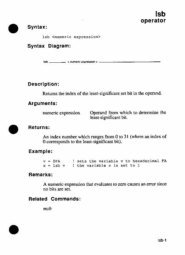
Isb operator
Syntax:
lsb <numeric expression>
Syntax Diagram:
Isb < numeric ex~ression r
Description:
Returns the index of the least-significant set bit in the operand.
Arguments:
numeric expression Operand from which to determine the least-significant bit.
Returns:
An index number which ranges from 0 to 3 1 (where an index of 0 corresponds to the least-significant bit).
Example:
v = $FA ! sets the variable v to hexadecimal FA x = lsb v ! the variable x is set to 1
Remarks:
A numeric expression that evaluates to zero causes an error since no bits are set.
Related Commands:
msb

Isb

mid function
Syntax:
mid s t r < s t r i n g > , from < s t a r t pos i t i on> , l e n g t h < length>
mid ( < s t r i n g > , < s t a r t p o s i t i o n > , < length>)
Syntax Diagram:
mld - str <string > , from <staflposirion > , length <length > -
Description:
Extracts a new string of the specified length from the given string beginning with the character at the specified index. The sum of the start position and the length number cannot exceed the number of characters in the string plus 1.
Arguments:
string String or string expression from which to perform extraction.
start position Integer expression. The left-most character of the string is position number 1.
length
Returns:
The extracted string .
Integer expression.

mid
Example:
x = m i d s t r "data 56" , f r o m 6 , l e n g t h 2 ! t h e var iable x i s set ! t o "56"

Syntax:
msb operator
msb <numeric expression>
Syntax Diagram:
msb < numeric expresshm >
Description:
Returns the index of the most-significant set bit in the operand.
Arguments:
numeric expression Operand from which to determine the most-significant set bit.
Returns:
An index number which rages from 0 to 31 (where an index of 0 corresponds to the least-significant bit).
Example:
x = msb $A ! the variable x is set to 3
Remarks:
A numeric expression that evaluates to zero causes an error since no bits are set.
Related Commands:
lsb

msb
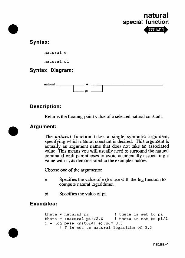
natural special function -
Syntax:
n a t u r a l e
n a t u r a l p i
Syntax Diagram:
natural I.: I Description:
Returns the floating-point value of a selected natural constant.
Argument:
The natural function takes a single symbolic argument, specifying which natural constant is aesireh. This arg;ment is actually an argument name that does not take an associated value. This means you will usually need to surround the natural command with parentheses to avoid accidentally associating a value with it, as demonstrated in the examples below.
Choose one of the arguments:
e Specifies the value of e (for use with the log function to compute natural logarithms).
pi Specifies the value of pi.
Examples:
t h e t a = n a t u r a l p i ! t h e t a i s set t o p i t h e t a = ( n a t u r a l p i ) /2 .0 ! t h e t a i s s e t t o p i / 2 f = l o g base ( n a t u r a l e),num 3.0
! f i s s e t t o n a t u r a l logar i thm of 3.0

natural
Remarks:
The natural function allows access to useful natural constants to maximum precision, without having to look them up and type them in by hand.
Related Commands:
log, sin, cos, tan

next statement
Syntax:
n e x t
Syntax Diagram:
next
Description:
Terminates a for . . . next block.
Example:
f o r k = 1 t o 100 ! b e g i n s a f o r ... n e x t b l o c k
n e x t ! ends a f o r ... n e x t b l o c k
Remarks:
The for . . . next block is provided for ANSI compatibility, but the recommended TL/1 structure is the loop for . . . end loop block.
Related Commands:
end, for, loop
For More Information:
The "Overview of TL/lU section of the Programmer's Manual.

next

open special function
Syntax:
open device <terminal name> [, as <as>] [,mode <mode>] [,term <termination char>]
open device <file name> [, as <as>] [, mode <mode>] [, term <termination char>]
open device <port name> [I, <option keyword> <option value>) 1 [, as <as>] [, mode <mode>] [,term <termination char>]
open device <window name> [I, <option keyword> <option value>)] [, as <as>] [, mode <mode>] [,term <termination char>]
open device <ieee-488 name> [, as <as>] [,mode <mode>] [,term <termination char>]
open 0
Syntax Diagram:
open 1
- mode <mode > - term < termination char >
- devlce < terminal name >
€ < file name > < port name >
< window name >
- < option keyword > < oprion value > - A A T Y
- < option keyword > < option value > - A A T T

open
Description:
Connects the program to a serial port, terminal, text file, or other interface for input or output by allocating the device to the program and returning an I/O channel number. It also sets parameters for serial ports and windows.
Arguments:
device Terminal name:
"/term 1 " for the operator's interface.
"/term2" for the programmer's interface.
File name:
The name of any text file enclosed in quotes.
Port name:
"/port1 " for RS-232 port1 "/po&" for RS-232 port2
Window name:
"/terml/win" for operator's display.
"/winv (or "term2lwin") for monitor. (Default = "/term1 ")

open
IEEE-488 interface or device name:
mode
*'/ieee** for the IEEE-488 interface.
"/ieee/address list" for one or more devices attached to the EEE-488 interface.
where address list is a list of comma-separated EEE-488 addresses. Each address is either a single radix 10 number indicating the device address or a pair of numbers separated by a colon character, indicating the primary and secondary addresses of the device. For example:
"heeel 1 " for the device at address 1.
"/ieee/2,4: 10" for the group consisting of the device at address 2 and the device with primary address 4 and secondary address 10.
"output", "update", "input", or "append". (Note: "update" is not allowed for file names.)
Default for terminal names: "update" Default for file names: "output" Default for port names: "update" Default for window names: "update" Default for EEE-488: "update"
"buffered" or "unbuffered". (Default = "buffered")
The mode argument determines how newline characters are translated by TL11 print, print using, input, or input using commands for serial ports, and how string values are input.

open
term The termination character string argument specifies the termination character to associate with the channel. The length of the string must be less than or equal to one character. If the length is zero, no termination character is associated with the channel. The termination character is used to mark the end of input records and is appended to printed expressions.
If the term argument is not supplied, the termination character default is the newline character. An exception to this is an IEEE-488 channel, where the default is the linefeed character.
The following option keywords apply only if the device is a window:
Option Option Keyword Value(s)
XO%, YOrg Numeric expressions for the location of the upper left-hand corner of the window in characters.
Default values: xorg = 0 yorg = 0
xdim, ydim Numeric expressions for the size of the window in characters.
Default values for operator's display: xdim = 42 ydim = 3
Default values for monitor: xdim = 80 ydim = 24

open
xscale, yscale Numeric expressions for the full-scale coordinates for objects to be displayed by a window. The maximum value for xscale and for yscale is 10000.
Default values: xscale = loo0 yscale = 1000
border A string expression for the title to be centered at the top of the border. If the string expression is a null string (""), the border will not have a title. (Default: no border)
The following option keywords apply only if the device is an RS-232-C"serial port:
Option Option Keyword Value(s)
speed Baud rate: 19200, 9600, 4800, 2400, 2000, 1800, 1200,600,300, 134, or 1 10.
bits Number of data bits: 5, 6,7, or 8.
stop Number of stop bits: 0, 1, or 2 (0 represents 1.5 stop bits).
parity "even", "odd", or "none".
stall Stall/Unstall control: "on" or "off'.
cts Clear-to-Send handshake: "on" or "off'.
autolf Auto linefeed: "on" or "off '.

Example 1:
i channe l = open dev ice "hexdata", a s " input"
Example 2:
f i l e 2 = open dev ice " /dr l / rombytes" , a s "output"
Example 3:
p l = open dev ice " / p o r t l W , speed 1200, b i t s 8, p a r i t y "even"
Example 4:
! Open a window on t h e monitor w i th i t s o r i g i n ! a t (20,6) and wi th a dimension of 40 by 12 ! ( c e n t e r e d on t h e d i s p l a y ) . F u l l - s c a l e ! c o o r d i n a t e s of t h e o b j e c t s t o be d i s p l a y e d ! i n t h e window a r e t o be (1000, 1000) .
channel = open dev ice "/winw, xorg 20, yorg 6, xdim 40, ydim 12, x s c a l e 1000, y s c a l e 1000
Remarks:
Input and output are handled through I/O channels. An 110 channel is a connection between W1 and the operating system. You create an I/O channel with the open command before conducting any input or output operations. When communication to an I/O channel is complete, you close the channel using the close command. Attempted access to a channel that has not already been opened results in a run-time error.
Typically, you open one channel for each device that requires input or output. You may open more than one channel to the same device, but this action is not recommended as it may result in non-standard operation.

open
The minimal open statement:
open 0
is used to open a channel to the operator's display and keypad for update. In this case, you need not specify the channel in subsequent print and input commands. Some other forms of the minimal open command include:
open device "/term2" ! programmer's i n t e r f a c e open device " / p o r t l W ! RS232C p o r t #1 open device " /por t2" ! RS232C p o r t #2 open device "/ieeeW ! IEEE-488 i n t e r f a c e open dev ice "/ ieee/lW ! IEEE-488 dev ice a t
add re s s 1
In these cases, channel specification with print or input is also optional.
You may open channels to the programmer's monitor and keyboard, the operator's display and keypad, the two RS-232 ports, to text files on the hard or floppy disk drives to the EEE- 488 interface, and to devices attached to the EEE-488 interface. Special rules apply to input and output depending on the device you are using. These rules are summarized below:
Operator's Display and Keypad - to open a channel to the operator's interface, specify "/terml" as the device name. TL/1 accesses the operator's display as a 3-line by 42-column text area and escape sequences for display attributes are recognized.
Input is read from the operator's keypad, including the soft keys and optional foot pedal (via the external switch interface). In the default line-buffered mode, the keypad alpha lock is engaged which causes each key press to return the alphabetical representation after the ENTER key is pressed. In the unbuffered mode, characters are sent to TL/1 immediately. If update mode is specified, input characters automatically appear on the display. The CLEAR key erases the keystrokes in the input buffer and on the display allowing for re-entry.

Monitor and Programmer's Keyboard - to open a channel to the programmer's interface, specify "Aerm2" as the device name. TL/l accesses the monitor through a text window, which becomes active until the TLI1 program completes execution. TL/1 accesses the monitor as an ANSI 3.64 compatible terminal. See Appendix B, "Control Codes for Monitor and Operator's Display," for more information. If a program which uses the monitor as an output channel is executed under the debugger, the message window will cover the debugger window.
Input is read from the programmer's keyboard. In line- buffered mode, characters are stored until the Return key is pressed. In unbuffered mode, characters are sent to TL/1 immediately. If update mode is specified, input characters automatically appear on the display, and the rubout key is used to erase characters before they are sent to TL/1. In addition, typing Ctrl-U will erase all the characters on a line and typing Ctrl-R will reprint a line. Tabs are converted to sequences of spaces.
Windows - to open a channel to a window, specify "/terml/win" as the device name for a window on the operator's display and "/winu (or "/term2/win") as the device name for a window on the monitor. These extensions allow window operations to be performed on /term1 and /term2 since they are actually implemented as windows covering each display.
A window is created with the open command. This allows normal print and input to be done on windows just as it is done on any other display device. Windows are permitted to overlap each other. What is displayed is determined by the order in which the windows were created. A new window is always on top of all the other windows. An existing window may be moved to the front or the back using the winctl command. The winctl command also permits making a window invisible by "hiding" it, and making an invisible window visible by "unhiding" it.

open
The location c specified by specified by x displayed in yscale. All rt sizes of object the full-scale xscaleand ysc is (500,500). only part of th
)f the upper, left-hand comer of a window is xorg and yorg. The size of a window is ;dim and ydim. The size of the object to be the window is controlled by xscale and :ferences to locations inside a window and :s displayed in a window are made relative to : coordinates specified. For example, if ale are both 1000, the center of the window If the object size is larger than the window,
e object will be visible at any given time.
All normal print and input statements operate on a window. Doing input on a window device open in update or read mode will cause input from programmer's keyboard (in the case of a window on the monitor) and from the operator's keypad (in the case of a window on the operator's display). Each window is an ANSI terminal with all of the escape sequences and control codes active as defined in Appendix B.
RS-232-C Ports - to open a channel to one of the two RS-232-C ports, specify either "Iportl" or "Iport2" as the device name.
When you open a port for input in buffered mode, characters are held until a carriage return character (hexadecimal OD) is read. Upon reading the carriage return, the input is sent to TL11. In unbuffered mode, characters are sent to TL/1 immediately.
When you open a port for update, the input characters are immediately echoed as output. If a delete character (hexadecimal 7F) is read as input, the last character is deleted and a backspace (08), space (hexadecimal 20), backspace (08) sequence is sent as output. If Ctrl-U is read as input, the input line is deleted. If Ctrl-R is read as input, all input since the last carriage return is re-sent as output. When a port is opened in any mode other than update, characters are not echoed, and the delete, Ctrl-U, and Ctrl-R characters have no special effect.

open
In both buffered and unbuffered mode, when XONIXOFF flow control is enabled, Ctrl-S is used to stall the output and Ctrl-Q is used to restore its flow.
IEEE-488 Interface and Devices - When the 9100A19105A is configured as an IEEE-488 talker/listener, the appropriate way to open the IEEE-488 interface is to open "Iieee". Since the 9 100Al9105A is not a controller and cannot address other devices to listen or talk, IEEE- 488 device name arguments containing an address list (e-g. "Iieeell", "/ieee/2,4:2") are not relevant to operation as a talker~listener. Values printed to and input from the IEEE- 488 interface are sent to and received from other devices on the IEEE-488 bus. It is the responsibility of the controller to ensure that the 9100N9105A is addressed to listen or talk at the appropriate times.
When the 9100A/9105A is configured as a controller, the IEEE-488 interface may be opened by opening device name "Iieee". A channel to a group of devices attached to the bus may be opened by opening device name "lieeeladdress list", where address list is a comma- separated list of IEEE-488 addresses (described in the Arguments section above). The former form of device name is principally useful for IEEE-488 bus control via the ieee command, while the latter form is useful for access by the print, input, poll, and ieee commands. Text Files on Disk - to open a channel to a text file on a disk, specify the file name as the device name. Text files may be opened:
- as output: this is the default. If the file named by the device <file name> option already exists, it is truncated to zero size; otherwise a new (empty) file having the specified name is created.
- as append: the file named by the device <file name> option is opened to permit print commands to place new data after the existing file contents. The file must already exist or an error will be reported.

open
- as input: the file named by the device <file name> option must already exist, or an error is reported. The next input command on the channel will read data starting at the beginning of the file.
It is an error to have more than one channel open to a particular file at any given time. It is also an error to open a text file for both read and write access at the same time or to open a text fde as "update."
Related Commands:
close, draw, draw ref, draw text, input, input using, poll, print, print using
For More Information:
The "Overview of TL11" section of the Programmer's Manual. The "Control Codes for Monitor and Operator's Display," appendix of this manual.
The "Operator's Keypad Mapping to TL11 Input," appendix in this manual. The "Programmer's Keyboard Mapping to TLI1 Input," appendix in this manual. The"9100Al9105A Error Numbers" appendix in this manual. The "IEEE-488, 9100A-015" section of the Technical User's Manual".
open

passes operator
Syntax:
<invocation> passes
Syntax Diagram:
c name> - passes
Description:
Tests the termination status of a called program or function. The passes operator evaluates as true if the called function or program ends with a "passes" status and as false otherwise.
Arguments:
Program or function call.
if testbus addr $8000 passes then y = 1
Example 2:
if testramfull addr $1000, upto $1FFF passes then x = l
Remarks:
Termination status indicates whether or not a UUT passes functional tests. Termination status is revised for every invocation.

passes
Termination status can be:
passes represents completion of a test without any unhandled fault conditions. The UUT is fiee from any faults that the test can detect.
fails represents the existence of one or more umepaired faults at the end of test execution.
A program that runs to completion without detecting any faults indicates that the UUT passes. Detection of a fault by the program (or any programs it calls) affects the termination status of the program. Any unhandled, unexercised fault condition causes the program to indicate that the UUT fails. Any fault condition that is exercised causes the program to indicate that the UUT fails if the last full iteration of the exerciser detected a fault and allows the program to indicate a "passes" if the last full iteration of the exerciser did not detect a fault. The termination status of a program is accumulated in the program that called it, so that if any called programs indicated a failure, the calling program also indicates that the UUT fails.
A fault condition can be handled by a block of statements called a fault condition handler. The fault condition handler has access to the arguments of the fault and the global variables of the test program. When a fault condition handler encounters either a return statement or its last statement the handler terminates, and execution resumes at the statement following the fault command.
If the handler does not execute a fault command, the fault condition is handled and disappears. In this case, the termi- nation status is "passes".
A fault command with no fault name or arguments unconditionally sets the termination status to "fails."
When a refault or a fault command with a fault name is executed, the termination status is affected by the presence of other handlers or exercisers for the fault condition.

- passes
Related Commands:
execute, exercise,fault,fails, handle, if, refault, while
For More Information:
The "Overview of TL/1" section of the Programmer's Manual.

passes
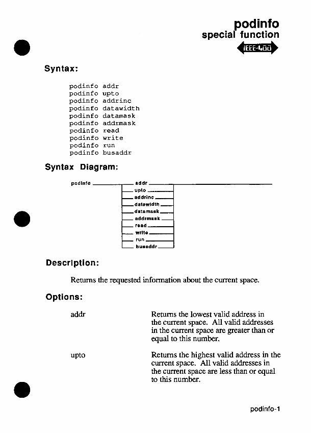
podinfo special function -
Syntax:
podinfo addr podinfo upto podinfo addrinc podinfo datawidth podinf o datamask podinfo addrmask podinfo read podinf o wri te podinfo run podinfo busaddr
Syntax Diagram:
podlnfo addr upto addrlnc datawldth - datamask- addrmask - road wrlto run busaddr -
Description:
Returns the requested information about the current space.
Options:
addr Returns the lowest valid address in the current space. All valid addresses in the current space are greater than or equal to this number.
Returns the highest valid address in the current space. All valid addresses in the current space are less than or equal to this number.

podinfo
addrinc
datawidth
datamask
addrmask
read
write
run
Returns the minimum valid address increment for the current space. All valid address increments are multiples of this number.
Returns the width, in bits, of the data words in the current space.
Returns a bitmask with bits set for the valid data bits in the current space.
Returns a bitmask of valid address bits. Note the least significant couple of bits may not be set if addrinc is greater than one.
Returns 1 if read is permitted in the current space and 0 otherwise.
Returns 1 if write is permitted in the current space and 0 otherwise.
Returns 1 if run UUT is permitted in the current space and 0 otherwise.
Returns the default bus test address. busaddr
Returns:
A number is always returned.
Examples:
function testme (addr, upto)
if addr < (podinfo addr) then fault\return if addr > (podinfo upto) then fault\return
testramfast addr addr upto upto, addrstep 2
end function

podinfo
Related Commands:
setspace, getspace, sysspace, podsetup, sysaddr, sysdata
For More Information:
The "Overview of TL\1 " section of the Programmer's Manual.
Supplemental Pod Information for 910019105A User's Manual.

podinfo

podsetup special function o j r )
Syntax:
podsetup ( <op t ion keyword> <opt ion va lue> ]
Syntax Diagram:
podsetup < option keyword > < option value >
A 1 - -
Description:
Accesses the pod to enable or disable reporting of faults directly sensed by the pod hardware.
Arguments:
O~tion Option Value(s)
'report power' "on" or "off". Enables or disables reporting of bad power supply level.
'report forcing' "on" or "off". Enables or disables reporting of active forcing-input lines.
'report intr' "on" or "off". Enables or disables reporting of active interrupt lines.
'report address' "on" or "off". Enables or disables reporting of undrivable address-output lines.

poasetup
'report data' "on" or "off". Enables or disables reporting of undrivable data bus lines.
'report con troll "on" or "off". Enables or disables reporting of undrivable control-output lines.
'report special' "on" or "off". Enables or disables reporting of special pod errors.
'enable string' "on" or "off". Enables or disables a pod-dependent forcing line. The enable phrases all begin: 'enable ' and end with a pod- dependent string.
timeout
option
<expression> Changes the timeout time. The expression must be numeric.
<value> A pod-dependent setup option. The option and value are defined by the pod data file.
Example 1:
podsetup ' r e p o r t power' "on"
Example 2:
podsetup ' enab le ready ' " o f f n
Example 3:
podsetup t imeout 1 0 0 0
Example 4:
podsetup ' r e p o r t i n t r ' "off ", r e p o r t power "of fw

podsetup
Remarks:
The podsetup function may be written in keyword notation only.
For More Information:
The "Overview of TL/lW section of the Programmer's Manual. Supplemental Pod Information for 91 OOA/9l O5A Users Manual. The Fluke pod manual for the microprocessor you are using.

podsetup

Syntax:
poll function
p o l l channel <channel>, event <condi t ion>
p o l l (<channel>, <condi t ion>)
Syntax Diagram:
p o l l channel <channel> , event <condition>
Description:
The poll function allows you to examine the status of a device for certain conditions. For most conditions, the poll function returns a 1 if the condition is present, a 0 if it is not.
a Arguments:
channel An expression which identifies an open channel.
condition "input", "output", "blocked", "errors", "break", or "srq".
"input" - One or more characters are available on an input channel. If the input is a file, the end-of-file character has not been reached. If the specified channel is not open for input, a 0 is returned.
"output" - The output buffer is empty on a serial channel open for output. If the channel is not open for output or is not a serial channel, a 0 is returned.

poll
"blocked" - Output to a serial device is blocked (suspended) waiting for necessary protocol signals (as in CTSIRTS).
"errors" - Parity, framing, or overrun errors have occurred on a serial channel open for input.
"break" - A break character has been detected on the serial channel open for input.
"srq" - (IEEE-488 channels only) If the channel is open on the IEEE-488 interface, then the poll command returns 1 if a device is asserting SRQ (Service Request) on the IEEE-488 bus, and 0 if no device is asserting SRQ. If the channel is open on a group of devices, a serial poll is performed on the first device in the address list, and the resulting serial poll status byte is used as the return value of the poll command. (The 9 lOOA19lOSA must be configured as a controller in order to conduct a serial poll.)
If an 110 error occurs while attempting to process the poll command (for example, a timeout error occurs while attempting to perform a serial poll on an IEEE-488 device), then the "io-error" fault is raised with numeric argument err-num containing the 9100A/9105A error number and string argument ercmsg containing a description of the error. For example, the following is a TLI1 code fragment for an io-error fault handler:
handle io-error(err-num, err-msg) declare numeric err-num declare string err-msg print using "Error ? # : ? # ' I , err-num, err-msg
end handle

0 Returns:
1, if condition exists.
0, if condition does not exist.
Note: The "srq" condition can return the result of performing a serial poll, as discussed above.
Example:
l oop while ( p o l l channel ichan, event " input" ) = 0 wai t t i m e 1000 ! wai t f o r i n p u t
end loop
Related Commands:
open
For More Information:
The "Overview of TLI1" section of the Programmer's Manual. The "9 lOOA/9 lO5A Error Numbers" appendix in this manual. The "IEEE-488, 9 100A-015" section of the "Technical User's Manual".

poll
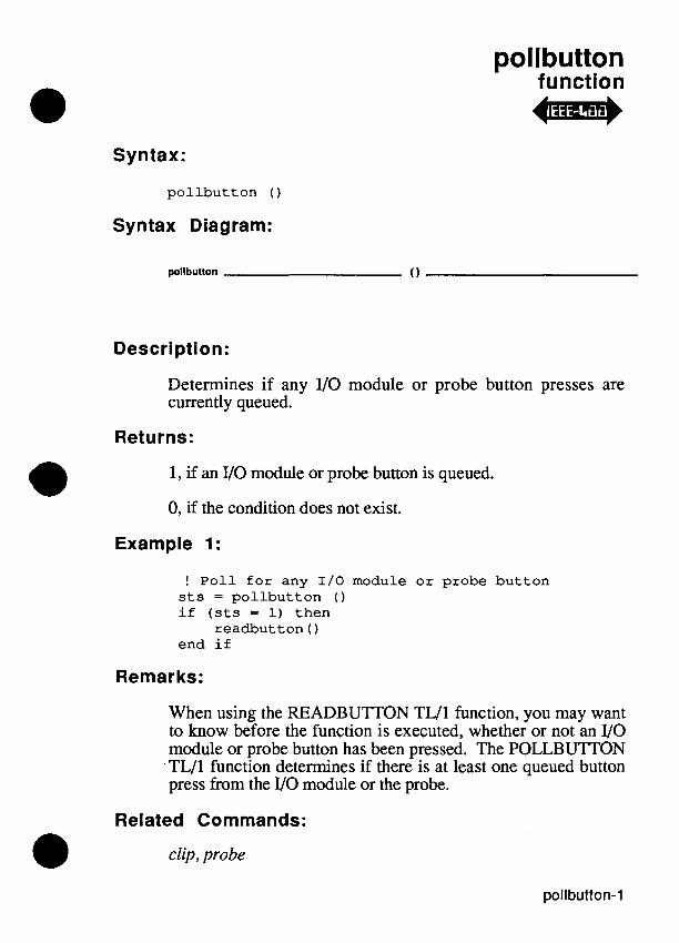
pollbutton function +-+
Syntax:
pollbutton ( )
Syntax Diagram:
pollbutton ( 1
Description:
Determines if any 110 module or probe button presses are currently queued.
Returns:
1, if an VO module or probe button is queued.
0, if the condition does not exist.
Example 1:
! Poll for any 1/0 module or probe button sts = pollbutton 0 if (sts = 1) then
readbutton ( ) end if
Remarks:
When using the READBUTTON TL/1 function, you may want to know before the function is executed, whether or not an VO module or probe button has been pressed. The POLLBUTTON TL/1 function determines if there is at least one queued button press from the VO module or the probe.
Related Commands:
clip, probe

pollbutton
For More Information:
The "Overview of TL11" section of the Programmer's Manual.

polluut function -*
Syntax:
p o l l u u t ( )
Syntax Diagram:
polluut - ( )
Description:
Determines whether the pod is executing instructions in the RUNUUT mode.
Returns: 1, if the pod is executing instructions in RUNUUT mode.
0, if the pod is not executing instructions in RUNUUT mode. This could be caused by any of the following reasons:
The pod wasn't put into RUNUUT mode.
The pod has halted RUNUUT execution after reaching a breakpoint.
A data compare equal (DCE) condition has occurred in an VO module.
Examples:
program look
runuut addr SFFFFFFO compare dev ice "/modl", p a t t " 1 1 0 1 1 1 0 1 "
(example is cont inued on t h e next page)
polluut
loop whi le p o l l u u t ( ) = 1 execu te io-stimulus ( ) ! a s t imu lus r o u t i n e
! you have w r i t t e n t o ! e x e r c i s e t h e 1/0 ! p o r t s of your UUT
end loop
end program
Related Commands:
compare, runuut, waituut
For More Information:
The "Overview of TL11" section of the Programmer's Manual.

POW function
Syntax:
pow num <expression I>, power <expression 2>
pow (<expression I>, <expression 2>)
Syntax Diagram:
pow - nu m < expression 1 > - , power < expression 2 >
Description:
Computes the value of one argument raised to the power of the other argument.
Arguments:
expression 1
expression 2
Returns:
A floating-point number.
Examples:
The floating-point value to raise by the power argument value.
The floating-point power argument value.
f = pow num 3.0, power 3.0 ! result is 27.0 f = pow (6.0, 1.0/3.0) ! result is cube root
! of 6.0

Remarks:
If any of the following is true, an error will result:
Both expression 1 and expression 2 are equal to 0.0.
The expression 1 value is negative.
Also, overflow errors may occur for certain ranges of argument values which cause excessively large returned values.
Related Commands:

pretestram function +m+
Syntax:
pretestram addr <addr>, upto <upto>, mask <mask>, addrstep <addrstep>
pretestram (<addr>, <upto>, <mask>, <addrstep>)
Syntax Diagram:
pretestram - addr < addr> - , upto < upto > ...
... - , mask <mask> - , addrstep <addrstep>
Description:
Performs a very fast pretest of RAM to find any simple faults such as a totally dead memory chip, stuck address lines, or stuck data lines.
Arguments:
addr Starting address.
upto Ending address.
mask Bit mask for data bits to test.
addrs tep Address increment.
Example:
if pretestram addr 0, upto SFFFE, mask SFFFF, addrstep 2 passes then
! If pretestram passes, do your customized ! test (or Pod Quick test) here.
(example is continued on the next page)

pretestram
! If your test finds an error, then execute ! diagnoseram, using the values for ! faultaddr, expdata, and data discovered by ! your program.
else
! No need to program anything. When ! pretestram fails, it has full diagnostics.
end if
Remarks:
The action of prestestram is included in testramfast and testramfull.
Related Commands:
diagnoseram, testramfast, testramfill
For More Information:
The "Overview of TL11" section of the Programmer's Manual.

print statement
Syntax:
p r i n t [<express ion l i s t>]
p r i n t [on <channel>] [, <express ion l i s t > ]
Syntax Diagram:
prlnt
- o n < channel >
Description:
Outputs character strings and numbers to a character-oriented output device.
A numeric expression that identifies a channel to a device open for output.
expression list One or more expressions for output separated by commas.
Example 1:
p r i n t " t e x t s t r i n g " ! output t o o p e r a t o r ' s d i s p l a y ! with no e x t r a spaces
Example 2:
p r i n t on c h l , " t e x t s t r i n g = ", t s ! output s t r i n g fol lowed by ! va lue of t s i n decimal

Remarks:
Before using the print command, the output device must be opened for output.
The print command without an "on" expression prints to the first device opened for output, append, or update. An error occurs if no device has been opened or if the device has subsequently been closed.
If an expression is a string, it is printed with no surrounding spaces. If an expression is numeric, it is printed in decimal with no surrounding spaces. If an expression is floating-point, it is printed in scientific notation format with six digits of precision following the decimal point.
The print command adds the termination character (which usually defaults to newline) associated with the channel after printing the last expression. A print command without any expression list prints a termination character (if any).
If the print channel is a serial port opened in buffered mode, the newline character is actually printed as either a carriage return or as a carriage return plus a line feed. This definition can be changed by pressing the SETUP MENU key and then the PORT1 or PORT2 softkeys found on the operator keypad. Output is not actually sent to a buffered serial port channel until a newline character is printed.
If the print channel is opened on either the IEEE-488 interface or a device attached to the IEEE-488 interface, EOI is automatically asserted with the termination character. In addition, if "EOI Enable" mode is turned on (see the ieee command for details), EOI is asserted with the last byte printed by the print command (which is not always a termination character, since the channel may have no associated termination character).

If an VO error occurs during an attempt to process a print command (for example, a timeout error during an attempt to print to an IEEE-488 device), then the io-error fault is raised, with numeric argument erxnum containing the 9lOOADl O5A error number, and string argument err-msg containing a description of the error. For example, the following is a TLl1 code fragment for an io-error fault handler:
handle io-error(err-num,err-msg) declare numeric err-num declare string err-msg print using "Error ?#:?#",err-num,err-msg
end handle
Related Commands:
open, print using
For More Information:
The "Overview of TLI1" section of the Programmer's Manual. The "Control Codes for Monitor and Operator's Display," appendix of this manual. The "9100Al9105A Error Numbers" appendix in this manual. The "IEEE-488,9105-015" section of the Technical User's Manual.


print using
Syntax: statement
p r i n t u s i n g <format s t r i n g > [, on <channel>] [, <express ion l is t>]
Syntax Diagram:
prlnt uslng < lormatstring r L , on < d a n n e ~ r -1 L , < expression k t r J
Description:
Outputs strings and numbers to a character-oriented output device in a specified format.
Arguments:
format string A string that defines the output format.
channel A numeric expression that identifies a device open for output.
expression list One or more expressions for output separated by commas.
Example 1:
p r i n t u s i n g " # # # # ####", 1, 2, 10, 110 ! ou tpu t s t h e s t r i n g : ! 1 2 10 110
Example 2:
p r i n t u s ing " f i r s t &&&&&&ti&, second %%%%, t h i r d i s # @ @ @ @ " , $FF, $10, 110
! ou tpu t s t h e s t r i n g : ! f i r s t 11111111, second 0010, t h i r d i s 0110
print using-1
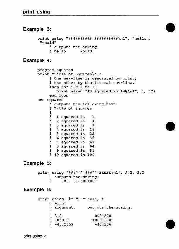
print using
Example 3:
p r i n t u s ing " # # # # # # # # # # ##########\n lW, "he l lo" , "world"
! ou tpu t s t h e s t r i n g : ! h e l l o world
Example 4:
program squa re s p r i n t "Table of s q u a r e s \ n l n
! One new-line i s gene ra t ed by p r i n t , ! t h e o t h e r by t h e l i t e r a l new-line. loop f o r i = 1 t o 10
p r i n t u s ing "#@ squared i s # # @ \ n l W , i, i * i end loop
end squa re s ! ou tpu t s t h e fo l lowing t e x t : ! Table of Squares ! ! 1 squared i s 1 ! 2 squared i s 4 ! 3 squared i s 9 ! 4 squared i s 16 ! 5 squared i s 25 ! 6 squared i s 36 ! 7 squared i s 49 ! 8 squared i s 64 ! 9 squared i s 81 ! 10 squared i s 100
Example 5:
p r i n t u s i n g "###"" " ###"""EEEEE\nlW, 3.2, 3.2 ! o u t p u t s t h e s t r i n g : I 003 3.2OOE+OO
Example 6:
p r i n t u s i n g "#""" . """ \nln, f ! with ! argument: ou tpu t s t h e s t r i n g : ! ! 3.2 003 .ZOO ! 1000.3 1000.300 ! -40.2359 -40.236
print using-2
print using
Example 7:
p r i n t u s i n g " ? # ?% ?@ ?& ? * \ n l W , $32, $32, $32, $32, 50.0
! o u t p u t s t h e s t r i n g : ! 50 32 50 110010 5.000000E+01
Remarks:
The print using command allows for highly structured or colurnnized output by use of format specifications contained in format smngs. Format smngs specify formatted output through combinations of literal characters and format pictures. There must be a format picture for every expression. It is a run-time error if there are more format pictures in the format smng than expressions in the expression list.
If no channel is specified in the print using command, output is directed to the first device opened for output, append, or update.
A print using command does not automatically output a termination character at the end of the output. To print a new- line character with the print using command, include 'Inl" in the format smng.
Characters in the format smng which are not part of a format picture are simply printed as given in the format string.
If the print channel is a serial port opened in buffered mode, the newline character is actually printed as either a carriage return or as a carriage return plus a line feed. This definition can be changed by pressing the SETUP MENU key and then the PORT1 or PORT2 softkeys found on the operator's keypad. Output is not actually sent to a buffered serial port channel until a newline character is printed.
If the print channel is opened on either the IEEE-488 interface or a device attached to the IEEE-488 interface, EOI is automatically asserted with the termination character (if any). In addition, if the 'EOI Enable' mode is turned on (see the ieee command for details), then EOI is asserted with the last byte printed by the print using command.
print using9

print using
If an VO error occurs while attempting to process a print using command (for example, a timeout error while attempting to print to an IEEE-488 device), the io-error fault is raised, with numeric argument ercnum containing the 9 100Al9 lO5A error number and string argument err-msg containing a description of the error. For example, the following is a TLI1 code fragment for an io-error fault handler:
handle io-error (err-num, err-msg) declare numeric err-num declare string err-msg print using "Error ? # : ?#Iv, err-num,
err-msg end handle
A format picture is a string of one or more format characters; a format string contains zero or more format pictures. Format pictures are one of two types: fixed-width and variable-width. Fixed-width format pictures output data in colurnnized format, while variable-width format pictures output data using the minimum number of columns needed to express the data. (The result for variable-width pictures is the same as that achieved with the print command, except that it is possible to control the radix when printing numeric values.)
print using-4

print using
Fixed-Width Formatted Output
A fixed-width string format picture is a string of one or more "#" characters, where each "#" character represents one character in the string data to be printed.
A fixed-width numeric format picture is a string of zero or more optional digit places (leading "#" characters) followed by one or more required digit places, which also determine the radix (hexadecimal, decimal, or binary) for numeric data.
A fixed-width floating-point format picture is a string of zero or more optional digit places (leading "#" characters), followed by a required digit sequence, optionally followed by the string "EEEEE" to denote the exponent. If the exponent sequence is included, the number will be printed in scientific notation; otherwise, it will be printed in fixed-point notation. For both notations, the required digit sequence contains "A" characters. In addition, fixed-point notation allows at most one decimal point character in the sequence of "A" characters to specify the position of the decimal point. (Note: At least one "A" character must precede the decimal point.)
The fixed-width format picture characters are defined below:
Symbol Description
# An optional digit place for numeric and floating-point formats or a character place for string formats. In numeric formats, if the place is a non-significant zero, a space is printed. When the "#" symbol appears as the last position of a numeric format picture, it is a required digit place and defines the radix to be decimal.
% A hexadecimal digit for numeric format pictures. If this digit is a non-significant zero, a zero is printed.
@ A decimal digit for numeric format pictures. If this digit is a non-significant zero, a zero is printed.
print using-5

print using
& A binary digit for numeric format pictures. If the digit is a nonsignificant zero, a zero is printed.
A Required digit place for floating-point numbers. A sequence of "A" characters may contain a single decimal-point character (which must be preceded by at least one character), or may be followed by a fixed sequence of five "E" characters denoting the exponent (in which case the sequence of "A"
characters may not include a decimal point).
When a numeric value is printed into a fixed-width format picture, the right-most digit place provides-the radix in which the number is printed. The character "%" in the right-most position causes the number to be printed in hexadecimal. The characters "#" and "@" cause the number to be printed in decimal. The character "&" causes the number to be printed in binary. If there are fewer characters in the format picture than there are significant digits in the number, a run-time error occurs. If there are fewer significant digits in the number than there are format picture characters, the number is right-justified in the format picture.
For example, the expression "10" will be printed as " A" with "#%" as the format picture, but it will be printed as "OA" with "%%" as the format picture.
When a fixed-width format picture is used to print a string, the string is left-justified in the picture. If there are more characters in the string than in the picture, a run-time error occurs. If there are fewer characters in the string than in the picture, the extra picture characters are replaced by spaces. Only the "#" character may represent string characters in a format picture. For example, the string "data" will be printed as "data " when "######" is used as the format picture.
print using-6

print using
Variable-Width Formatted Output
Like a fixed-width format picture, a variable-width format picture describes the format for a single data value. The difference is that a variable-width format picture prints as many characters as are necessary to express the corresponding value. The result for each value is identical to what is generated by the print command, except that it is possible to specify the radix to use for printing a numeric value.
A variable-width format picture consists of a single "?" character, followed by a single character denoting the picture type-
The following special picture type characters are defined:
Symbol Description
# Print a variable-width string or decimal number.
% Print a variable-width hexadecimal number.
@ Print a variable-width decimal number.
& Print a variable-width binary number.
A Print a variable-width floating-point number (in scientific notation with six digits of precision following the decimal point).
? Print a single "?" character.
If the picture type character is not one of the above, then it will be printed literally (the same as if it had not been preceded by a "?" character).
Related Commands:
open, print
print using-7

print using
For More Information:
The "Overview of TL/1" section of the Programmer's Manual. The "9100A/9105A Error Numbers" appendix in this manual.
The "IEEE-488 9105-015" section of the Technical User's Manual.
print using-8

probe function 47-
Syntax:
p r o b e r e f < r e f p i n >
p r o b e ( < r e f p i n > )
Syntax Diagram:
p r o b e ref <refpin>
Description:
Prompts the operator (on the operator's display) to probe the specified pin and press the ready button on the probe.
Arguments:
ref pin Name of pin to probe.
Example:
probe r e f "Ul-1"
Remarks:
This command is used to verify that the probe is set up for a measurement. The 9 lOOA/9 lO5A waits until the probe button is pressed before continuing on past this command.
For More Information:
The "Overview of TW1" section of the Programmer's Manual.

probe

program statement block
Syntax:
program <program name> [(<argname> { , <argname>))]
Syntax Diagram:
p r o g r a m <program name r
( -r 1 a r g y - n )
Description:
Specifies the beginning of a program block.
Arguments:
program name Name of the program defined on the lines following the program statement.
argname Name of an argument for this program.
Example 1:
program t e s t 8
end program
Example 2:
program m y g r o g ( a , b, c )
end m y g r o g

program
Example 3:
program 'my.filel ! Single quotes allow the ! use of a period in ! the program name.
end program
Remarks:
The first statement of every TL11 program must be a program statement. The program statement contains the program name and the names of any arguments passed to the program. The program block must be terminated with an end program statement or an end statement containing the same program name.
The name in the program and end statements must be the same. A valid program name contains from 1 to 10 characters and consists of only letters, numbers, and underscore characters (or periods, if the program name is enclosed in single quotes). A program name cannot be the same as the name of a built-in function.
Although TLl1 requires that a program name be spelled exactly the same wherever it appears, the case of letters is ignored when a program is looked up on the disk. Thus it is not possible to define two program names that differ only in case (such as PROGl and prog 1).
The scope of a program name is the UUT directory containing it plus the program library. Therefore, a program can call any other program in the same UUT directory, but not in another UUT directory.
The program argument list consists of one or more argument names, separated by commas; the argument list is enclosed in parentheses. The order of the names in this list is the same order in which the values for these arguments must be listed in positional notation calls to this program. If any arguments have default values, these values are assigned in the subsequent declaration blocks.

program
Program arguments may not be declared as arrays nor as global or persistent variables.
Declarations consist of any and all declaration blocks, function definition blocks, handler definition blocks, and exerciser definition blocks.
Related Commands:
declare, end, execute, exercise, function, handle, return
For More Information:
The "Overview of TLI1" section of the Programmer's Manual.

program

pulser function
Syntax:
p u l s e r mode <mode name>
p u l s e r (<mode name>)
p u l s e r 0
Syntax Diagram:
Description:
Turns on the probe in a pulser mode synchronized as specified by the sync command. The probe can pulse low, high, or toggle alternately high and low.
Arguments:
mode name "off", "high", "low", or "toggle". (Default = "off ')
Example:
p u l s e r mode " toggle"
Remarks:
When the probe threshold is set to RS-232, a low level is pulsed to 0 volts. Since this is not a valid RS-232 low level, the green light of the probe will not be illuminated.
Related Commands:
sync

pulser
For More Information:
The "Overview of TLI1" section of the Programmer's Manual.
rampaddr function
Syntax:
rampaddr addr <address>, mask <mask>
rampaddr (<address>, <mask>)
Syntax Diagram:
rampaddr - addr caddress> , mask <mask>
Description:
Performs a series of read operations, each at a different address. The number of reads and the values of the addresses are determined by the specified mask.
-
Arguments:
address Address.
mask
Example 1:
Hexadecimal mask of ramp bits.
rampaddr addr $1000, mask 3
The 9 100A/9 105A performs the following:
read addr $1000 read addr $1001 read addr $1002 read addr $1003

rampaddr
Example 2:
rampaddr addr $123B, mask $42 ! 123B hexadecimal = 0001 0010 0011 1011 b ina ry ! 42 hexadecimal = 0000 0000 0100 0010 b ina ry
The 9 1 O O A D 1 O5A performs the following:
read addr $1239 ! 0001 0010 0011 1001 b ina ry read addr $123B ! 0001 0010 0011 1011 b ina ry read addr $1279 ! 0001 0010 0111 1001 b ina ry read addr $127B ! 0001 0010 0111 1011 b ina ry
Remarks:
In the second example, the mask (42 hex) specifies the two address bits, 6 and 1. Four read operations are performed (2 raised to the power of 2.) The bits specified in the mask are ramped from all zeros to all ones with the right-most bit (bit 1) considered the LSB and the left-most bit (bit 6) considered the MSB of the ramped bits. The other address bits remain unaltered. It is much faster to ramp in groups of smaller masks (FO, F, FOO) than to ramp one large mask (FFF), although the larger mask provides more complete coverage.
For More Information:
The "Overview of TL/1" section of the Programmer's Manual.

rampdata function 4m+
Syntax:
r a m p d a t a addr < a d d r e s s > , data < d a t a > , m a s k < m a s k >
r a m p d a t a ( < a d d r e s s > , < d a t a > , < m a s k > )
Syntax Diagram:
rampdata - addr <address z , data <dafa> , mask <mask>
Description:
Performs
Arguments: -
address
data
mask
Example:
a series of write operations at the specified address.
Address.
Fist data value.
Hex mask of the data bits to be ramped.
r a m p d a t a addr $123B , data $ 2 5 , m a s k $ 4 3 ! data 2 5 h e x = 0 0 1 0 0 1 0 1 b i n a r y ! m a s k 4 3 h e x = 0 1 0 0 0 0 1 1 b i n a r y
The system performs eight writes as shown below:
w r i t e addr $123B , data $ 2 4 ! 0 0 1 0 0 1 0 0 w r i t e addr $123B, data $ 2 5 ! 0 0 1 0 0 1 0 1 w r i t e addr $123B, da ta $ 2 6 ! 0 0 1 0 0 1 1 0 w r i t e addr $123B, da ta $ 2 7 ! 0 0 1 0 0 1 1 1
( e x a m p l e i s c o n t i n u e d o n t h e n e x t page)

rampdata
w r i t e addr $123B, data $ 6 4 ! 0 1 1 0 0 1 0 0 w r i t e addr $123B, da ta $ 6 5 ! 0 1 1 0 0 1 0 1 w r i t e addr $123B, da ta $ 6 6 ! 0 1 1 0 0 1 1 0 w r i t e addr $123B, da ta $ 6 7 ! 0 1 1 0 0 1 1 1
Remarks:
You specify the original data and the data bits to be ramped. In the previous example, the mask (43 hex) specifies the three data bits 6, 1 and 0. This means that there are eight write operations (2 raised to the third power). The data bits are ramped from all zeros to all ones with the right-most bit (bit 0) considered the LSB and the left-most bit (bit 6) considered the MSB of the ramped bits. The other data bits remain unaltered.
The following command performs a ramp for an eight-bit pod that is equivalent to the 9000-series RAMP @ 1 122 command:
r a m p d a t a addr $ 1 1 2 2 , data 0 , m a s k $FF
This statement performs 256 writes (data 00-FF) at address 1 122 on a 16-bit pod.
Similarly, the following command performs 65536 writes (data 0000 - FFFF) at address 1122:
r a m p d a t a addr $ 1 1 2 2 , data 0 , m a s k $FFFF
For More Information:
The "Overview of TLIl " section of the Programmer's Manual.

random function
Syntax:
random [seed <expression>]
random ( [<expression>] )
Syntax Diagram:
I ( )
random smd < expression :, I
Description:
Produces pseudorandom sequences of numbers.
Arguments:
seed Providing this optional the sequence of numbers. (Default = $FFFFFFFF)
value changes
Returns:
Returns a pseudorandom 32-bit numeric value.
Example:
loop for i = 1 to 100 ! print 100 random numbers print random ( )
end loop

random
Remarks:
The seed argument can change the sequence of pseduorandom numbers that are generated by the random function. Setting the seed to zero begins a new sequence of numbers based on the current time of day.
Setting the seed to any number other than zero or $FFFFFFFF, begins a new sequence based on that number. Using the same number again generates the same sequence of numbers.
The seed value can also be set to $FFFFFFFF (Default), which returns the next number in the current pseudorandom sequence.
The sequence of numbers returned by random has the appearance of randomness, but no specific property of the sequence is guaranteed. The sequences of numbers generated by random may change in subsequent software revisions to provide more nearly random sequences.
For More Information:
The "Overview of TL11" section of the Programmer's Manual.

read function
Syntax:
r e a d a d d r < a d d r e s s >
r e a d ( < a d d r e s s > )
Syntax Diagram:
read add r < address r
Description:
Returns the data located at the specified address.
Arguments: address Address from which to read data.
Returns:
The data read at the specified address.
Example 1:
d a t a 2 = r e a d a d d r h e r e ! Reads t h e d a t a a t t h e a d d r e s s s p e c i f i e d by ! t h e v a l u e of t h e u s e r - d e f i n e d v a r i a b l e h e r e ! and s t o r e s i t i n t h e v a r i a b l e d a t a 2 .
Example 2:
d a t a 2 = r e a d ( h e r e ) ! The p o s i t i o n a l n o t a t i o n e q u i v a l e n t ! of t h e keyword n o t a t i o n i n t h e above ! example.

read
Example 3:
data1 = read ($8FFO) ! Reads the hex data at ! address 8FF0 into ! the variable datal.
For More Information:
The "Overview of TL/l" section of the Programmer's Manual.

read block function +-*
Syntax:
readblock file <file name>, format <format>, addr <address I>, upto <address 2,
readblock (<file name>, <format>, <address I>, <address 2,)
Syntax Diagram:
readblock - lllo < file name r , format < formal r ...
. - , addr caddress 1 r , upto caddress 2r
Description:
Reads the data from the specified address range and stores this data in the specified text file.
Arguments:
file name
format
address 1
address 2
The name of the file in which to store the data. If a full path name is not specified, the data will be stored in the specified file in the current UUT directory.
The ASCII format in which the data was previously stored. Either "motorola" or "intel". (Default="motorola".)
Start address.
End address.
read block
Example 1:
readblock file "testlcd", format "motorola", addr $7000, upto $7FD4
Example 2:
readblock ("pgml", "motorola", $1000, $lFFF)
Example 3:
readblock file "/HDR/testdataW, format "motorola", addr $7000, upto $7FD4
Related Commands:
loadblock, writeblock
For More Information:
The "Overview of TL11" section of the Programmer's Manual.

readbutton function
Syntax:
readbut ton mode <mode>
readbut ton (<mode>)
readbut ton ( )
Syntax Diagram:
( 1 readbutton I mode < m d e z I
Description:
Waits for you to press the VO module or probe button.
Arguments:
mode "beep" or "nobeep". Default = "beep"
Returns:
The name of the device that is selected.
Example 1:
! Wait f o r any 1/0 module o r probe bu t ton dev ice = readbut ton ( )
Example 2:
! Wait f o r probe bu t ton with no beep device = readbut ton ("nobeep")
! va lue of device v a r i a b l e i s now "/probew

readbutton
Example 3:
! Wait f o r 1/0 Module bu t ton with beep dev ice = readbut ton mode "beep"
! va lue of dev i ce v a r i a b l e i s now "/mod4BW
Remarks:
It is often inconvenient to continue pressing the <RETURN> key on the programmer's keyboard or the <ENTER/YES> key on the operator's keypad while probing points on a UUT. The readbutton command delays program execution until the If0 module or probe button can be pressed.
When the proper button is pressed, the function returns with the name of the device.
Related Commands:
clip, probe
For More Information:
The "Overview of TL/1" section of the Programmer's Manual.

readdate function 4m*
Syntax:
r eadda t e t i m e <express ion>
r eadda t e (<express ion>)
Syntax Diagram:
r e a d d a t e tlme i expression z
Description:
Returns a string which contains the date. To access the current date, the expression should be the value returned from the systime funchon.
Arguments:
expression A number returned by the systime function that represents a number of elapsed seconds.
Returns:
A string representing a date.
Example:
t = sys t ime 0 X = r eadda t e t i m e t ! S t o r e s t h e d a t e
! from v a r i a b l e t i n s t r i n g ! format i n t h e v a r i a b l e X
p r i n t r eadda t e ( t ) ! P r i n t s t h e d a t a from ! v a r i a b l e t i n s t r i n g format

readdate
Remarks:
The readdate function returns a string containing the date in the format:
where YYYY = year, MM = month, and DD = day.
For example, the string "1986/07/06" represents July 6, 1986.
Related Commands:
readtime, systime
For More Information:
The "Overview of TL/lW section of the Programmer's Manual.

readmenu function
Syntax:
readmenu channel <channel express ion>, i d e n t i f i e r <menu name> [, name < te rmina l name>] [, s t y l e < s t y l e > ] [, xorg <xloca t ion>] [, yorg <y loca t ion>] [, he igh t <he ight>]
Syntax Diagram:
readmenu - channel <channel expression D - , Identiller <menuname> - ...
... ... , name < terminal name D L, s t y l e < s t y / e > -..I
... L , xorg <xlocation D A L , xorg < ylocation D J L , height < height D J
Description:
Used to display and read from a menu defined by the define menu command.
Arguments:
channel expression A numeric expression to define a channel opened to read key presses used to make menu selections. Note that /term1 and /term2 are also considered windows.
menu name
terminal name
A menu name as defined by the define menu command. If the menu does not exist, readmenu returns an empty string (fff').
The name of the display device to draw the menu on. The only name allowed is "Iterrn2" (this is also the default value).

readmenu
style
xlocation
ylocation
height
0 - The menu is a non-button menu (Default).
1 - The menu is a button menu.
A numeric expression that defines the horizontal location of the upper left- hand comer of the menu in characters.
If xorg is not specified, the default is to center the menu on the display.
A numeric expression that defines the vertical location of the upper left hand comer of the menu in characters.
If yorg is not specified, the default is to center the menu on the display.
A numeric expression that defines the maximum height of the menu in characters. If not specified, it defaults to the size required to list all the menu items.
Returns:
A string indicating which menu item is selected.
Example 1:
response = readmenu channe l channe l , i d e n t i f i e r "MI"
! Read from menu M1
Example 2:
r e s p o n s e = readmenu channe l channe l , i d e n t i f i e r WM2 W
! Read from menu M2

readmenu
Example 3:
Pop up a menu when t h e u s e r pushes a key. On subsequent key p r e s s e s , s t a r t t h e menu a t t h e l a s t p l a c e t h e u s e r was on t h e menu. I f t h e u s e r makes no s e l e c t i o n , e x i t t h e program loop . This example assumes t h e u s e r has w r i t t e n a program c a l l e d doac t ion which causes t h e a c t i o n i n d i c a t e d by t h e menu s e l e c t i o n t o be done.
keyboard = open dev ice " / t e r m l M , a s " input" , mode "unbuffered"
response = "MI" notdone = 1 loop whi le notdone
i f ( p o l l channel keyboard, event " input" ) t hen response = readmenu channel keyboard,
i d e n t i f i e r response i f response = "" t hen
notdone = 0 else
doac t ion a c t i o n response end i f
end i f end loop
Remarks:
Menus are drawn in two styles, button or no button. In the no button style, a menu is simply a list of selectable items. In the button style, the menu is drawn as a collection of buttons with a box drawn around each menu item.
The user can type keys to make a menu selection if keys were defined for that menu. The keys defined are displayed in front of each menu item.
There is also a menu cursor displayed in a menu. The menu cursor is shown by inversing the active field. To select the item at the menu cursor enter a carriage return. To select a submenu at the menu cursor (submenus are drawn with a "->" appearing in the right hand side of the menu item) enter a carriage return or a right arrow key. To move the menu cursor down, press the

readmenu
down arrow key, and to move the menu cursor up, press the up arrow key. The height argument specifies the maximum height of the menu on the screen. If the menu items will not fit in the height specified, the menu becomes a scrollable menu. This is indicated by the menu having the word "More" and a down arrow appear on the bottom border. Pressing the cursor down key on the last visible field causes the menu to scroll down. The word "More" and an up arrow now appears on the top border to indicate the menu may be scrolled up by pressing the up arrow on the top most visible field.
If a selection is made by the user, a string indicating that selection is returned. That string is of the form MMM1- 1111/MMM2-1112/MMM3-1111, where 1111 is the selection made on menu MMM3, a submenu of menu MMM2 which is a submenu of MMM1. If the size of the string is larger than 255 characters, a string overflow error will be generated.
A menu can be forced to start up at a particular selection or submenu by passing the menu name of a particular selection. The menu name is of the form returned when a menu selection is made. For example, to start a menu in a submenu selection, pass menu as "MMM1-IIIlIMMM2-1111".
If the menu style was 1 (indicating buttons), readmenu will accept escape sequences from a touch-sense interface. The escape sequence recognized is "/lB[>2;xxxnW. The xxx is the location on the screen, assuming the screen is divided into 10 columns by 12 rows. The locations are numbered from 000 (the upper left comer) through 119 (the lower right comer).
The device is a channel opened for reading by the open command. It is recommended that this channel be opened as "input" mode "unbuffered". If the channel is buffered, you will have to type line terminators to cause menu action and this is probably undesirable. This channel will be flushed before characters are read if it is not a disk file.

readmenu
xorg and yorg specify the position of the menu on the screen in character cells in the default font. If xorg is missing, xorg will default to center the menu horizontally, and if yorg is missing, yorg will default to center the menu vertically.
Related Commands:
define menu, remove menu, open
For More Information:
The "Overview of TL/ lM section of the Programmer's Manual.

readmenu

readout function
Syntax:
readout dev i ce <device l i s t>
readout (<device l i s t>)
readout ( )
Syntax Diagram:
readout i i s > I
Description:
Reads response data from the VO module or the probe, and stores it in the system's memory. The response data is then available via the sig, count, and level commands.
Arguments:
device list VO module name, clip module name, probe name, or combinations of these. (Default = "/probe")
Example 1:
mod = c l i p r e f "u3" , p i n s 4 0
arm dev ice mod rampdata addr 0 , d a t a 0 , mask SFF rampdata addr 0 , d a t a 0 , mask SFFOO
readout dev i ce mod
readout
Example 2:
arm device "/modl, /mod2"
readout device "/modl,/mod2"
Remarks:
The readout command terminates signature gathering started by the arm command. Therefore arm and readout should be considered as beginning and ending statements for a TL/1 response-gathering block.
Related Commands:
arm, checkstatus, clip, count, level, sig, stopcount, sync
For More Information:
The "Overview of TL/1" section of the Programmer's Manual.

readspecial function 4m+
Syntax:
readspecial addr <address>
readspecial (<address>)
Syntax Diagram:
readspeclal - addr <address r
Description:
Returns the data located at the specified virtual address. This allows access to the virtual addresses that, in some pods, are used for special operations. This command should only be used when you know that the normal read command does not provide the required special operation.
Arguments:
address Address from which to read data.
Returns:
The data at the specified address.
Example 1:
value = readspecial addr $F0000018
Example 2:
value = readspecial ($F0000018)

readspecial
Remarks:
Incorrect use of this special-purpose command can place the pod and the 91004/9105A mainframe in inconsistent states.
For More Information:
The "Overview of TL11" section of the Programmer's Manual. The Fluke pod manual for the microprocessor you are using.

readstatus function 0-4
Syntax:
r e a d s t a t u s ( )
Syntax Diagram:
readstatus ( 1
Description:
The readstatus command reads the values on the status lines of the pod. To interpret the status data, refer to the pod's o~erator 's manual. As with the read function, a value is aicessed by assigning the function invocation to a variable.
Returns:
The status word.
Example:
s t a t u s = r e a d s t a t u s ( ) ! t h e v a r i a b l e s t a t u s i s ! loaded wi th d a t a from ! t h e f u n c t i o n r e a d s t a t u s
Related Commands:
writecontrol
For More Information:
The "Overview of TL/lW section of the Programmer's Manual.
readstatus-l
readstatus

readtime function @mp
Syntax:
read t ime t i m e <express ion>
read t ime (<express ion>)
Syntax Diagram:
Description:
Returns a string containing the time. To access the current time, the expression should be the value returned by the systime function.
Arguments:
expression A number returned by calling systime, or a number representing elapsed seconds.
Returns:
A string representing a time.
Example 1:
t = sys t ime ( ) p r i n t " the t i m e i s ", readt ime t i m e t
! p r i n t s " the t i m e i s 15:36:58 ( o r ! whatever t i m e t h e va lue of t i n d i c a t e s )
readtime
Example 2:
start = systime 0 testuut print "TestUUT time ", readtime (systime 0 - start)
! prints: "TestUUT time 00:05:03" if, ! testuut took five minutes and three ! seconds to execute.
Remarks:
The readtime function returns a string containing the time in the format:
where HH = hours, MM = minutes, and SS = seconds.
For example, the string " l5:36:58" represents 36 minutes and 58 seconds past 3 o'clock in the afternoon. In this format, a list of strings ordered by the ASCII value of the characters from left to right is also ordered chronologically.
Related Commands:
readdate, systime
For More Information:
The "Overview of TL/1 " section of the Programmer's Manual.

readvirtual function +m+
Syntax:
readvirtual extaddr <extended address>, addr <address>
readvirtual (<extended address>, <address>)
Syntax Diagram:
readvlrtual - oxtaddr < extentedaddress D , addr < address D
Description:
Readvirtual is a complete replacement for the obsoleted readspecial command. Returns the data located at the specified virtual address. This allows access to the virtual addresses that, in some pods, are used for special operations. This command should only be used when you know that the normal read command does not provide the required special operation.
Arguments:
extaddr Upper 32-bits of virtual address.
addr Address from which to read data.
Returns:
The data at the specified address.
Example 1:
value = readvirtual extaddr 0, addr SF0000018
Example 2:
value = readvirtual (0, SF0000018)

readvirtual
Remarks:
Incorrect use of this special-purpose command can place the pod and the 9 1 OON9 1 O5A mainframe in inconsistent states.
For More Information:
The "Overview of TL11" section of the Programmer's Manual. The Fluke pod manual for the microprocessor you are using.

readword function 4m*
Syntax:
r e a d w o r d [device < I / O m o d u l e n a m e > ] [, w o r d < w o r d number>] [, m o d e < m o d e > ]
r e a d w o r d ( < I / O m o d u l e n a m e > , < w o r d number> , < m o d e > )
Syntax Diagram:
word < word number >
mode <mode>
Description:
Allows a group of I/O module pins to be read as a single group of values.
Arguments:
I/O Module name I/O module name ("/mod1 ", "/mod2", "/mod3 ", or "/mod4"). (Default = "/mod 1 ")
word number The number of the word group. Valid values are from 1 through 5. (Default = 1)
mode The mode in which to read the word. Valid values are "now" or "stored". (Default = "now")
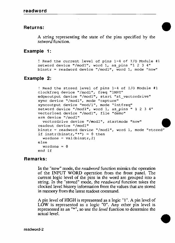
readword
Returns:
A string representing the state of the pins specified by the setword function.
Example 1:
! Read t h e c u r r e n t l e v e l of p i n s 1 -4 of 1 / 0 Module #1 setword dev ice "/modlW, word 1, a s g i n s "1 2 3 4" b i n s t r = readword dev ice "/modln, word 1, mode "now"
Example 2:
! Read t h e s t o r e d l e v e l of p i n s 1 - 4 of 1 / 0 Module #1 c l o c k f r e q dev ice "/modl", f r e q "1MHZ" edgeoutput dev i ce "/modl", s t a r t "at-vectordr ive" sync dev ice "/modln, mode "capture" syncoutput dev i ce "mod/l", mode " i n t f r e q " setword dev ice "/modll', word 1, a s g i n s " 1 2 3 4" vec to r load dev ice "/modl", f i l e "demo" arm dev ice "/modln
v e c t o r d r i v e device "/modl", s tar tmode "now" readout dev i ce "/modln
i f i n s t r ( b i n s t r , " * " ) = 0 t hen b i n s t r = readword dev ice "/modl", word 1, mode "s tored"
wordone = v a l ( b i n s t r , 2) else
wordone = 0 end i f
Remarks:
In the "now" mode, the readword function mimics the operation of the INPUT WORD operation from the front panel. The current logic level of the pins in the word are grouped into a string. In the "stored" mode, the readword function takes the clocked level history information from the values that are stored in memory from the latest readout command.
A pin level of HIGH is represented as a logic "1 ". A pin level of LOW is represented as a logic "0". Any other pin level is represented as an "*", so use the level function to determine the aciual level.

readword
Setword can make pin grouping assignments. Groupings may be made from 1 to 40 pins.
Related Commands:
setword, writeword
For More Information:
The "Overview of TLI1" section of the Programmer's Manual.

readword
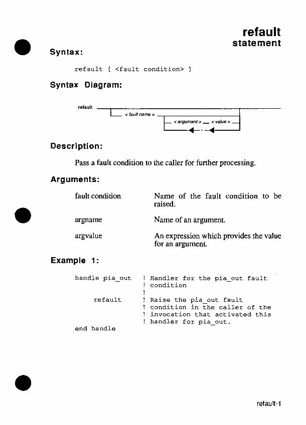
Syntax:
refault statement
r e f a u l t [ < f a u l t cond i t i on> ]
Syntax Diagram:
refault
c fault name z
c argument z - c value z - A , 7
Description:
Pass a fault condition to the caller for further processing.
Arguments:
fault condition Name of the fault condition to be raised.
argname Name of an argument.
An expression which provides the value for an argument.
Example 1:
handle pia-out ! Handler f o r t h e pia-out f a u l t ! c o n d i t i o n !
r e f a u l t ! Raise t h e pia-out f a u l t ! cond i t i on i n t h e c a l l e r of t h e ! i nvoca t ion t h a t a c t i v a t e d t h i s ! hand le r f o r pia-out.
end handle

refault
Example 2:
I n t h i s example, t h e o u t e r program c a l l s t h e i n n e r f u n c t i o n which r a i s e s a f a u l t c o n d i t i o n c a l l e d f a u l t l . Af t e r t h e handler p roces se s t h e f a u l t cond i t i on , it may wish t o r a i s e it t o t h e a t t e n t i o n of a hand le r a c t i v a t e d by t h e o u t e r program. The r e f a u l t command a l lows r a i s i n g t h e same f a u l t c o n d i t i o n i n t h e c a l l i n g b lock .
program o u t e r
handle f a u l t 1 ! Handler f o r t h e f a u l t ! f a u l t cond i t i on
p r i n t "execut ing o u t e r ' s handler" f a u l t ! Se t t e rmina t ion s t a t u s t o
! " f a i l s " end handle
func t ion i n n e r handle f a u l t l ! Another handler f o r t h e
! f a u l t l f a u l t cond i t i on p r i n t "execut ing i n n e r ' s handler" r e f a u l t ! Re-raise t h e same f a u l t
! cond i t i on i n t h e c o n t r o l ! program
end handle
i f s u b c i r c u i t 5 ( ) f a i l s t hen ! Test s u b - c i r c u i t 5 ! f o r f a u l t s
f a u l t f a u l t l !Raise t h e f a u l t l ! f a u l t cond i t i on
end i f end func t ion
execu te i n n e r ( )
end program

refault
I n t h i s example, t h e hand le r f o r f a u l t 2 i n t h e i n n e r f u n c t i o n wants t o r a i s e a d i f f e r e n t f a u l t cond i t i on , bu t doesn ' t want t o a c t i v a t e t h e hand le r f o r t h a t f a u l t t h a t i s a c t i v a t e d i n t h e i n n e r f u n c t i o n . The r e f a u l t command r a i s e s t h i s new f a u l t c o n d i t i o n i n t h e block t h a t c a l l e d t h e i n n e r f u n c t i o n ( i n t h i s case , t h e o u t e r program).
program o u t e r
handle f a u l t 1 ! Handler f o r t h e f a u l t 1 ! f a u l t cond i t i on
p r i n t "execut ing o u t e r ' s handler f o r f a u l t 1"
f a u l t ! Set t e rmina t ion s t a t u s ! t o " f a i l s "
end handle
f u n c t i o n i n n e r
handle f a u l t 2 ! Handler f o r t h e f a u l t 2 ! f a u l t c o n d i t i o n
p r i n t "execut ing i n n e r ' s handler" r e f a u l t f a u l t l ! Raise t h e f a u l t l
! f a u l t cond i t i on i n t h e ! o u t e r program, no t i n ! t h e i n n e r f u n c t i o n
end handle
handle f a u l t 1 p r i n t "execut ing i n n e r ' s handler
f o r f a u l t l " end handle

refault
i f s u b c i r c u i t l 6 ( ) f a i l s t h e n ! T e s t s u b - c i r c u i t 1 6
f a u l t f a u l t 2 ! R a i s e t h e f a u l t 2 ! f a u l t c o n d i t i o n
e n d i f
e n d f u n c t i o n
e x e c u t e i n n e r ( )
e n d program
Remarks:
The refault command is an advanced feature for fault condition handling. You will not need it for most test programs.
The purpose of the refault command is to permit fault condition handlers at outer levels of a program to see fault conditions even though they have been handled at a lower level. Once a fault condition is handled, it normally disappears. A fault command in the handler could be used to preserve the (failure) termination status for the program, but if the fault command has the same fault condition as the name of the handler, an infinite recursion will occur.
This recursion can be avoided by using a refault command instead of a fault command. When the refault command is used in a handler, the effect is as if the fault condition that invoked the handler had been raised in the invocation that activated that handler. This insures that the current handler is not invoked again, thereby avoiding an infinite recursion.
Using the refault command without a fault name raises the fault condition that invoked the handler, but raises it in the calling block. Using the refault command with a fault name raises the new fault condition in the calling block.

refault
Related Commands:
abort, fault, handle, return
For More Information:
The "Overview of TL11" section of the Programmer's Manual.

refault

remove function
Syntax:
r e m o v e m e n u [ < m e n u n a m e > ]
r e m o v e m o d e [ < m o d e n a m e > ]
r e m o v e p a r t [ < p a r t n a m e > ]
r e m o v e ref [ < r e f n a m e > ]
r e m o v e t e x t [ < t e x t n a m e > ]
Syntax Diagram:
menu <name> mode <name> part <name> ref <name> text <name>
Description:
Removes definitions made by the define commands.
Options:
menu name: The name of the menu definition to remove from the list of menu definitions. If the menu string is of the form "MMMM", that menu is removed. If the menu string is of the form "MMMM-1111", that menu item is removed, but the rest of the menu remains. If the name is the null string (""), all of the menu definitions are removed.

remove
mode name: The name of the mode definition to remove from the list of mode definitions. If the name is the null string (""), all of the mode definitions are removed. A comma-separated list of mode names (with no spaces in the list) allows more than one mode definition to be removed
part name:
ref name:
text name:
The name of the part definition to remove from the list of part definitions. If the name is the null string (""), all of the part definitions are removed. A comma-separated list of part names (with no spaces in the list) allows more than one part definition to be removed.
The name of the reference designator definition to remove from the list of ref definitions. If the name is the null string (""), all of the ref definitions are removed. A comma-separated list of ref names (with no spaces in the list) allows more than one ref name to be removed.
The name of the text definition to remove from the list of text definitions. If the name is the null string (""), all of the text definitions are removed. A comma-separated list of mode names (with no spaces in the list) allows more than one text name to be removed.
Example 1:
remove p a r t "" ! Remove a l l p a r t d e f i n i t i o n s
Example 2:
remove p a r t "box" ! Remove t h e p a r t d e f i n i t i o n ! named "boxw

remove
Example 3:
r e m o v e ref "" ! R e m o v e all ref d e f i n i t i o n s
Example 4:
r e m o v e m e n u "MI" ! R e m o v e m e n u M1
Example 5:
r e m o v e m e n u "M1-a" ! R e m o v e i t e m a f r o m m e n u M1
Remarks:
Removing a definition frees up any memory used by that definition. All of the definitions are removed automatically at the start of each new TL/1 invocation. A new TL11 invocation is started by pressing the REPEAT or EXEC keys on the operator's keypad or by pressing the EXECUTE or INIT softkeys when in the debugger.
Related Commands:
defne mode, define menu, define part, define ref, define text
For More Information:
The "Overview of TLJ1" section of the Programmer's Manual.

remove
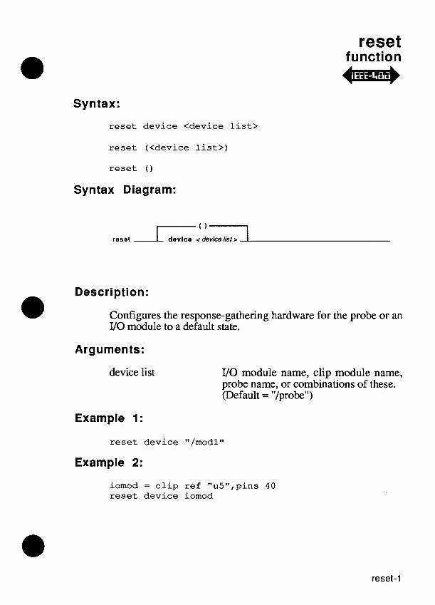
reset function O j *
Syntax:
reset device <device l i s t >
reset (<device l i s t > )
reset ( )
Syntax Diagram:
Description:
Configures the response-gathering hardware for the probe or an VO module to a default state.
Arguments:
device list VO module name, clip module name, probe name, or combinations of these. (Default = "/probeM)
Example 1:
reset device "/modlW
Example 2:
iomod = c l i p ref "u5",pins 4 0 reset device iomod

reset
Remarks:
The settings as a result of reset are as follows:
counter = "transition"
edge = "+" (rising edge for external start, stop, and clock
enable = "always"
sync = "pod for an 110 module = "freerun" for the probe
threshold = "ttl"
stopcount = "1"
syncoutput= "intfreq"
edgeoutput= "+" (rising edge for drive start, stop, and clock)
enableoutput "a1 ways"
clockfreq = "1MHz"
Also note that although the syncoutput, edgeoutput, enableoutput, and clockfreq settings are reset, they are only used when a 9 100-0 17 Vector Output I/O Module is connected.
In addition, all 110 module lines are placed in the high- impedance state.
For More Information:
The "Overview of TL/l" section of the Programmer's Manual.

resetpersvars function
Syntax:
resetpersvars ( )
Syntax Diagram:
resetperwars ( )
Description:
Resets the persistent variable set to the empty set.
Examples:
For each of the following example programs, assume that the persistent variable set initially contains:
Name Type Value
P V ~ numeric 3 P V ~ string rrfoorr P V ~ string "barrr
After executing the following command:
resetpersvars ( )
the persistent variable set is empty.
After executing the following program:
program progl declare persistent numeric pvl resetpersvars ( ) pvl = 4
end program
resetpe rsvars-1

resetpersvars
the persistent variable set contains:
Name Type Value
P V ~ numeric 4
After executing the following program:
program prog2 d e c l a r e p e r s i s t e n t s t r i n g pv2 d e c l a r e p e r s i s t e n t s t r i n g pv3 func t ion •’00
d e c l a r e p e r s i s t e n t s t r i n g pv2 end f u n c t i o n r e s e t p e r s v a r s ( )
foo 0 end program
the persistent variable set contains:
Name Type Value
P V ~ s t r i n g "f oo"
Remarks:
A local copy of any persistent variables known by the currently executing TL/1 program is retained, along with the current values. If any such persistent variables are subsequently redeclared or are assigned a value, they are added back to the persistent variable set.
The resetpersvars command allows purging of the persistent variable set, which would otherwise accrete forever (or until power was cycled).
Related Commands:
clearspersvars

restorecal function
Syntax:
r e s t o r e c a l [from <uut-userdisk>,name<name>]
r e s t o r e c a l (<uut-userdisk>, <name>)
r e s t o r e c a l ( )
Syntax Diagram:
restorecai I name <name>
Description:
Restores the calibration values for the I/O module and the probe from the requested UUT or USERDISK.
Arguments:
uut-userdisk USERDISK or UUT Default = "USERDISK"
name
Example 1:
USERDISK or UUT name Default = "" (current USERDISK or UUT)
! r e s t o r e c a l i b r a t i o n va lues from t h e c u r r e n t UUT r e s t o r e c a l from "UUT"
Example 2:
! r e s t o r e c a l i b r a t i o n v a l u e from t h e U U T DEMO r e s t o r e c a l from "UUT", name "DEMO"

restorecal
Example 3:
! res tore c a l i b r a t i o n va lue f r o m U S E R D I S K / D R 1 restorecal f r o m "USERDISK" , n a m e " / D R l W
Remarks:
This function is similar to the front panel RESTORE CALDATA operation and restores calibration values from a TL11 program. Calibration values may be restored from a USERDISK or UUT.
If the name of the USERDISK or UUT is the null string (""), then the current USERDISK or UUT is used. If the USERDISK or UUT is named, the calibration values are restored from the named USERDISK or UUT. Calibration values are restored for all VO modules and the probe.
For More Information:
The "Overview of TL11" section of the Programmer's Manual.

return statement
r e t u r n [<express ion>]
Syntax Diagram:
return L < expression > J
Description:
Causes a program, function, handler, or exerciser to terminate. Execution continues at the statement following the invocation statement (for programs and functions) or at the statement following the fault command (for handlers).
The value to return.
Returns:
As an option, the value of an expression can be returned when a function or program terminates.
Example 1:
r e t u r n ! Return c o n t r o l t o c a l l i n g program
Example 2:
r e t u r n d + 1 ! Return c o n t r o l t o c a l l i n g program. ! The va lue t h a t t h e func t ion ! r e t u r n s , i s t h e va lue of t h e ! v a r i a b l e d, p l u s 1.

return
Remarks:
The value of an expression can be returned when a program or function terminates. When the program or function is invoked as part of an expression the returned value is used in the expression.
A program or function that returns a value must do so explicitly. A program or function may not return values of two different types or return a value in one place without returning a value in every other place.
After the last statement of a block is executed, a return command is performed implicitly.
Related Commands:
execute, exercise, finction, handle, program
For More Information:
The "Overview of TL/lW section of the Programmer's Manual.

rotate function
Syntax:
r o t a t e a d d r < a d d r e s s > , d a t a < d a t a >
r o t a t e ( < a d d r e s s > , < d a t a > )
Syntax Diagram:
rotate - addr <address > , data <data >
Description:
Writes a data pattern to the specified address. The data is then rotated to the right and a write operation is performed. This is repeated as many times as there are data bits. Therefore, the last write performed writes the original data rotated one bit left.
Arguments:
address All write operations are written to this address.
data Initial data value.
Examples:
r o t a t e a d d r $FFFFE, d a t a $1234
The system performs the following sixteen operations:
w r i t e a d d r $FFFFE, d a t a $1234 w r i t e a d d r $FFFFE, d a t a S091A w r i t e a d d r $FFFFE, d a t a $048D w r i t e a d d r $FFFFE, d a t a $8246 w r i t e a d d r $FFFFE, d a t a $4123 w r i t e a d d r $FFFFE, d a t a $A091
(example i s c o n t i n u e d on t h e n e x t p a g e )

rotate
w r i t e addr SFFFFE, w r i t e addr $FFFFE, w r i t e addr SFFFFE, w r i t e addr SFFFFE, w r i t e addr SFFFFE, w r i t e addr SFFFFE, w r i t e addr SFFFFE, w r i t e a d d r $FFFFE, w r i t e addr SFFFFE, w r i t e addr SFFFFE,
da ta $DO48 da ta $ 6 8 2 4 da ta $3412 data SlA09 data $8D04 data $4682 da ta $ 2 3 4 1 data $91AO data $48DO data $ 2 4 6 8
For More Information:
The "Overview of TL/l" section of the Programmer's Manual.

runuut special function
Syntax:
runuut addr <address 1 > [, break <address 2>]
Syntax Diagram:
runuut - addr caddress 1 >
L , break <address 2 > J
Description:
Causes the UUT to begin executing instructions from its own memory, asynchronously to the system.
0 Arguments: address 1 Start address.
address 2 Break address.
Example 1:
runuut addr $ 1 2 3 5 ! start at hex address 1 2 3 5
Example 2:
runuut addr (read addr SFFFE) ! start at address read from location FFFE
Example 3:
runuut addr $1235 , break $2000 ! start at hex address 1 2 3 5 ! stop at hex address 2 0 0 0

runuut
Remarks:
Typically, runuut would be followed by waituut with a suitable maxtime value which would allow the UUT time to complete its operation.
Some pods have a breakpoint capability which can optionally be enabled by specifying a stop address with the "break" argument. Generally, pods designed before the 80286-era cannot use the "break" feature. Refer to your pod manual for more specific information.
Execution of runuut continues until one of the following events occurs:
The pod encounters a breakpoint.
A DCE condition occurs.
A hultuut is executed.
The time specified in a waituut expires.
The RESET key is pressed on the operator's keypad.
The RUN UUT HALT command is entered from the operator's keypad.
Faults which occur during the execution of runuut are reported on the subsequent haltuut or waituut. Attempts to perform any pod-related operations except waituut, haltuut, or polluut will result in an error if the runuut is still active. You must execute haltuut or waituut before attempting any other pod-related operations.
Related Commands:
compare, hultuut, polluut, waituut

runuut
For More Information:
The "Overview Manual.
of TL/ln section of the Programmer's
The Fluke pod manual for the microprocessor you are using.

runuut

special fbnction @m+
Syntax:
runuutspecial addr <address 1> [, break <address 2>]
runuutspecial (<address I>, <address 2>)
runuutspecial ( )
Syntax Diagram:
runuutspeclal
addr < address I r
break < address 2 r
Description:
Causes the UUT to begin executing instructions from its own memory, asynchronously to the system. Execution begins at the virtual address specified. If none is specified, runuutspecial defaults to an address that is pod dependent.
Arguments:
address 1 Virtual start address.
address 2
Example 1:
Stop address. (Default = 0)
runuutspecial ( ) ! start at pod-dependent starting ! address.
Example 2:
runuutspecial addr (read addr SFFFE) ! start at virtual address read from ! location FFFE

runuutspecial
Example 3:
runuutspecial addr $1235, break $2000 ! start at h e x virtual address 1235 ! stop at h e x address 2000
Remarks:
Some pods have special addresses where a runuut may begin. Such addresses may read a reset or interrupt vector from memory and begin execution at that address.
Typically, runuutspecial would be followed by waituut with a suitable maxtime value that allows the UUT time to complete its operation.
Some pods have a breakpoint capability which can optionally be enabled by specifying a stop address with the "break" argument. Generally, pods designed before the 80286-era cannot use the "break" feature. Refer to your pod manual for more specific information.
Execution of runuutspecial continues until one of the following events occurs:
The pod encounters a breakpoint.
A DCE condition occurs.
A haltuut is executed.
The time specified in a waituut expires.
The RESET key is press on the operator's keypad.
The RUN UUT HALT command is entered from the operator's keypad.

runuutspecial
Faults that occur during the execution of runuutspecial are reported on the subsequent haltuut or waituut. Attempts to perform any pod-related operations except waituut, haltuut, or polluut results in an error if the runuutspecial is still active. You must execute haltuut or waituut before attempting any other pod- related operations.
Related Commands:
compare, haltuut, polluut, waituut, runuut
For More Information:
The "Overview of TL/1 " section of the Programmer's Manual. The Fluke pod manual for the microprocessor you are using.
Supplemental Pod Information for 91 00Al91 O5A User's Manual.

runuutspecial

runuutvirtual special function
4 j * Syntax:
runuutvirtual [extadddr <ext>,] addr <address 1> [, break <address 2>]
runuutvirtual (<address 1>, caddress 2>)
runuutvirtual ( )
Syntax Diagram:
runuutvirtual extaddr c ext 2
Description:
Runuutvirtual is a compete replacement for the obsoleted runuutspecial command. Runuutvirtual causes the UUT to begin executing instructions from its own memory, asynchronously to the system. Execution begins at the virtual address specified. If none is specified, runuutvirtual defaults to an address that is pod dependent.
Arguments:
ext Extended address bits used to form virtual addresses from address 1 and address 2.
address 1 Start address.
address 2
Example 1:
Breakpoint address. (Default = 0)
runuutvirtual ( ) ! start at pod-dependent starting ! address.

runuutvirtual
Example 2:
r u n u u t v i r t u a l addr ( r e a d addr SFFFE) ! s t a r t a t v i r t u a l address read from ! l o c a t i o n FFFE
Example 3:
r u n u u t v i r t u a l addr $1235, break $2000 ! s t a r t a t hex v i r t u a l add re s s 1235 ! s t o p a t hex address 2000
Remarks:
Some pods have special addresses where a runuut may begin. Such addresses may read a reset or interrupt vector from memory and begin execution at that address.
Typically, runuutvirtual would be followed by waituut with a suitable maxtime value that allows the UUT time to com~lete its operation.
Some pods have a breakpoint capability which can optionally be enabled by specifying a stop address with the "break" argument. Generally, pods designed before the 80286-era cannot use the "break" feature. Refer to your pod manual for more specific information.
Execution of runuutvirtual continues until one of the following events occurs:
The pod encounters a breakpoint.
A DCE condition occurs.
A hultuut is executed.
The time specified in a waituut expires.
The RESET key is press on the operator's keypad.
The RUN UUT HALT command is entered from the operator's keypad.

runuutvirtual
Faults that occur during the execution of runuutvirtual are reported on the subsequent haltuut or waituut. Attempts to perform any pod-related operations except waituut, haltuut, or polluut results in an error if the runuutvirtual is still active. You must execute haltuut or waituut before attempting any other pod- related operations.
Related Commands:
compare, haltuut, polluut, waituut, runuut
For More Information:
The "Overview of TLI1" section of the Programmer's Manual. The Fluke pod manual for the microprocessor you are using. Supplemental Pod Information for 91 00Al91 O5A Users Manual.

runuutvirtual

setbit operator
Syntax:
s e t b i t <number>
Syntax Diagram:
setblt - <number>
Description:
Calculates the number that results from setting the bit whose index is given by the operand.
Arguments:
number Index on bit to set.
x = s e t b i t 3 ! t h e v a r i a b l e x i s s e t t o 8
Remarks:
An argument value greater than 3 1 (decimal) causes an error.
Related Commands:
bitmask

setbit

setoffset function
Syntax:
s e t o f f s e t [device <device name>] [, o f f s e t <value>]
s e t o f f s e t (<device name>, <value>)
s e t o f f set ( )
Syntax Diagram:
setoffset device < device name z
offset <value :, . e I ' Description:
Sets the delay offset for the specified I/O module or probe device. The value entered is biased by a value of 1000000 (decimal). For example, if data is to be sampled 10 nanoseconds before the calibration point, enter a value of 999990 (decimal). The delay lines in the hardware (I10 module or probe) will be set to the closest tap possible, which provides the desired delay offset. The I/O module has a resolution of about 15 nanoseconds per tap, and the probe has a resolution of about 4 nanoseconds per tap.
Each sync mode has a separate offset associated with it. For this reason, changing sync modes will change the offset.
Arguments:
device name I/O module name or probe name. (Default = "/probeM)
value Desired offset from calibration point. The value entered is biased by 1000000 (decimal). (Default = 1000000)

setoffset
Returns:
Returns a status of 1 or 0. A one indicates that the setting of the offset was successful (within the range of the hardware). A zero indicates that when setting the offset with the current calibration value, the resulting delay line setting is out of the range of the hardware. In this case, the hardware will still be set as close as possible to the desired offset; that is, the offset will be set to either the maximum or minimum of its range, depending on the offset value.
Example 1:
! Set an offset of -10 nanoseconds for the ! probe in pod address sync
sync device "/probew mode "pod" sync device "/podw, mode "addr" offset - value = 1000000 - 10 sts = setoffset device "/probew, offset offset value if (sts-= 1) then
print "setoffset succeeded" else
print "setoffset failed" end if
Example 2:
! Set an offset of 0 nanoseconds for 1/0 ! module 1 in pod data sync
sync device "/modlW, mode "pod" sync device "/podw, mode "data" offset-value = 1000000 sts = setoffset device "/modlW, offset offset-value if (sts = 1) then
print "setoffset succeeded" else
print "setoffset failed" end if

setoffset
Example 3:
! Set an offset of 25 nanoseconds for 1/0 ! module 4 in ext sync
sync device "/mod4", mode "ext" offset value = 1000000 + 25 sts = setoff set device "/mod4", off set off set-value if (sts = 1) then
print "setoffset succeeded" else
print "setoffset failed" end if
Remarks:
The setoflset command is valid only if the sync mode is "pod" or "ext"
In most cases, this function will not need to be used. Once the probe and VO module have been calibrated to a particular pod, their delay lines will have been set properly for the selected sync mode. But if special situations arise, where it is desired to "move" the clock point around, this command can be used.
These offsets are always relative to an edge. The calibration procedure for the probe and VO module finds the correct delay settings for a particular edge (for example, falling edge of ALE on the 8088 pod in address sync mode). The calibration procedure then sets an offset from that edge as defined in the pod database. When calibrating to ext, the offset is set to zero. This setoflset command allows other values of offset to be used, rather than these defaults.
Remarks concerning example 1 (using pod sync):
In the 80286 pod, assume that address sync is specified to occur 45 nanoseconds prior to the rising edge of signal -S 1. When calibration is performed, the hardware delay lines will be set as close as possible to this point. If getoffset is performed at this point, it will return a value of 999955 (decimal) or a value close to that, since the hardware provides delays in incremental values. If it is desired to sample a signal 20 nanoseconds before

setoffset
the rising edge of -S 1, an offset of 999980 (decimal) would be used. If it is desired to sample a signal exactly on the edge of -S1, an offset of 1000000 (decimal) would be used. And if it was desired to sample 35 nanoseconds after -S1, an offset of 1000035 (decimal) would be used.
Remarks concerning example 3 (using external sync):
If getoffset were performed just after an external calibration, the offset would return 1000000 (decimal) or some number near 1000000. This indicates that data will be sampled on the edge of the clock signal. If it is desired to sample the signal 28 nanoseconds before the clock edge, the offset would be set to 999972 (decimal). Likewise, sampling after the clock edge would require an offset value greater than 1000000 (decimal).
The range of the setofset command may vary from unit to unit. You need to be careful with programs that require large offsets. These offsets may be legal on some units but illegal on others. The recommended procedure is to determine the allowable range of offsets for a particular sync mode, and then make sure that some guard band is left. This range can be determined by selecting two very large offsets, such as +I000 nanoseconds and -1000 nanoseconds. Since these values will drive the hardware to its maximum settings, performing a getofset will return the maximum and minimum allowable offset values respectively.
Related Commands:
arm, getofset
For More Information:
The "Overview of TL11 " section of the Programmer's Manual. The "Offset Command" section of the Programmer's Manual for information on using offsets with GFI.

setspace function
Syntax:
setspace space <expression>
se tspace (<expression>)
Syntax Diagram:
setspace - space < expressh >
Description:
Sets the address space to the specified number.
Arguments:
expression A value returned by getspace or sysspace.
Example:
program t e s t15 s = getspace space "memory", s i z e "byte" setspace space s ! Sets the address space
! parameters.
s 2 = sysspace ( ) ! Saves t he last-used ! address space parameters.
execute t e s t12 ! Suppose the program tes t12 ! changes the address space.
setspace space s 2 ! Restores t he o r i g ina l ! address space parameters.
end program

Remarks:
Set the address space to the number returned by sysspace or getspace. It is meaningless to give setspace a number other than one returned by getspace or sysspace. An invalid space will cause an error.
Related Commands:
getspace, sysspace
For More Information:
The "Overview of TLI1" section of the Programmer's Manual. Appendix I, "Pod-Related Information," in this manual.

setword function
Syntax:
setword [device <device name>] [, word <word number>] [, a s g i n s <pins>]
setword (<device name>, <word number> , <pins>)
Syntax Diagram:
word < word number >
asglns < pin6 >
Description:
Allows pin numbers to be grouped together to form a user defined word. Setword is identical to the front panel operation IOMOD SET WORD. Up to 40 unique pins may be grouped together for each VO module in five different groups.
Arguments:
device name 110 module name, ("/mod1 ", "/mod2", "/mod3 'I, or "/mod4"). (Default = "/mod1 ")
word number The number of the word group. Valid values are from 1 through 5. (Default = 1)
pins A string of from 1 through 40 unique pin numbers. (Default = "40 39 38 37 ... 4 3 2 1")

setword
Example 1:
setword device "/modlW, word 1, a s g i n s "1 2 3 4"
Example 2:
setword device "/modlW, word 5, a s g i n s "40 39 2 1"
Remarks:
The setword function is identical in operation to the front panel operation IOMOD SET WORD. The purpose of this command is to group together user related pins to form specific words for use with the readword and writeword commands.
Only unique pin numbers between 1 and 40 inclusive are valid.
Related Commands:
readword, writeword
For More Information:
The "Overview of TL/lU section of the Programmer's Manual.

shl operator
Syntax:
<expression 1> shl [<expression 2>]
Syntax Diagram:
< expression 1 > T ::I J L < e x p r b Y i m r > J
Description:
Shifts the operand left by either one bit, or a specified number of bits. The first operand is shifted left: by one bit if the second operand is omitted, or by the number of bits specified by the second operand.
Arguments:
expression 1 The operand to be shifted left.
expression 2 The number of bits to shift. (Default = 1)
Returns:
The shifted number.
Example 1:
x = 7 shl ! the variable x is set to E
Example 2:
x = 7 shl 2 ! the variable x is set to 1C
Example 3:
x = 12 shl 2 ! the variable x is set to 30 ! hexadecimal
Remarks:
The symbol, << , also denotes the shl operation.
An error is raised if expression 2 is greater than decimal 31.
Since shl operations are carried out from right to left,
a shl b shl c
is the same as:
a shl (b shl c)
Related Commands:
shr

shr operator
0 Syntax: <expression 1> s h r [<expression 2>]
Syntax Diagram:
Description:
Shifts the operand right by either one bit, or a specified number of bits. The first operand is shifted right: by one bit if the second operand is omitted, or by the number of bits specified by the second operand.
The operand to be shifted right.
expression 2 The number of bits to shift. (Default = 1)
Returns:
The shifted number.
Example 1:
y = $19 s h r ! t h e v a r i a b l e y i s s e t t o C
Example 2:
y = $19 s h r 3 ! t h e v a r i a b l e y i s s e t t o 3
Example 3:
y = 1 9 s h r 3 ! t h e v a r i a b l e y i s s e t t o 2

shr
Remarks:
The symbol, >> , also denotes the shr operation.
An error is caused if expression 2 is greater than decimal 3 1.
Since shr operations are carried out from right to left,
a s h r b s h r c
is the same as:
a s h r (b s h r C )
Related Commands:
shl

sig function
Syntax:
s i g [device <device name>] [, p i n <p in number>] [, r e f p i n < r e f p i n name>]
s i g (<device name>, <p in number>, < r e f p i n name>)
Syntax Diagram:
dovlco < devicenamer pl n < pin number r rolpln < refpinnamer
Description:
Returns the signature for one pin. The signature can be requested either in terms of an VO module pin, a component pin, or the probe. This command will return useful information only after an am . . . readout block has taken a measurement.
Arguments:
device name VO module name, clip module name, probe name, or reference designator. (Default = "/probeM)
pin number
refpin name
Pin number of device specified. (Default = 1)
Specifies the device and pin in string format. The refpin argument is used to override the device and pin values. (Default = "")

Returns:
The 16-bit signature read.
Example 1:
modlist = clip ref "U3" , pins 40 modsig = sig device "U3" , pin 12
! Get sig on U3 pin 12
Example 2:
modsig = sig device "/modl", pin 12 ! Get sig on pin 12 of I/O module 1
Example 3:
modsig = sig ("/modlA", 12,"") ! Get sig on pin 12 of 1/0 module 1, clip A ! A refpin value must be supplied.
Remarks:
The signature can be requested for a specific pin of an I10 module by specifying the module name ("Imodl", "/mod2", etc.) as the device argument. The pin argument is interpreted as an UO module pin. Refer to Appendix E for tables that show what VO module pin numbers to use for every possible clip module.
If a component name ("Ul", "U2", etc.) is specified as the device argument, the pin argument is interpreted as a component pin. The sig function determines the VO module and pin number that corresponds to the specified component pin. The named component must have been previously named in a clip command.
If the smng value for refpin is not a null smng (""), the values of the device and pin arguments are ignored.
The sig function should be called only after the execution of an arm . . . readout block.
sig
Related Commands:
arm, count, level, readout
For More Information:
The "Overview of TLI1" section of the Programmer's Manual.


sin function
Syntax:
s i n ang le <express ion>
s i n (<expression>)
Syntax Diagram:
sln angle < expression >
Description:
Returns the sine function of the floating-point argument value.
Argument:
expression The floating-point argument value, expressed in radians.
Returns:
A floating-point number
Examples :
f = s i n ( ( n a t u r a l p i ) / 2 . 0 )
f = s i n ang le t h e t a
Related Commands:
asin, natural

sin

sqrt function
Syntax:
sqrt num <expression>
sqrt (<expression>)
Syntax Diagram:
sqrt nu m c expression r
Description:
Returns the square root of a floating-point argument value.
Arguments:
expression A floating argument value, which must be greater than or equal to 0.0.
Returns:
A floating-point number.
Examples:
f = sqrt num f f = sqrt (3.0)
Related Commands:

sqrt

stopcount function
Syntax:
stopcount [device <device list>] [,count <number>]
stopcount (<device list >, <number>)
stopcount ( )
Syntax Diagram:
stopcount
Description:
Sets the programmable stop count that turns off the response- gathering hardware after the specified number of enabled clock pulses. The stopcount function assigns this feature to the probe or a single VO module and specifies the value of the stop count (1-65535).
Arguments:
device list
number
VO module name, clip module name, probe name, or combinations of these. (Default = "/probe")
Number of clock pulses that the response-gathering hardware should count. (Default = 1)

stopcount
Example:
mod = c l i p r e f "u55", p i n s 2 4 s topcount dev i ce mod, count 1 0 0
Remarks:
When using stopcount, the edge command is required to set the stop condition to "count".
To get the same count as that entered at the operator's keypad, use a decimal number for the stopcount.
Example: stopcount count 1000
Related Commands:
a m , edge, readout
For More Information:
The "Overview of TL/lW section of the Programmer's Manual.

storepatt function
Syntax:
s t o r e p a t t dev i ce <device name>, p i n <p in number>, p a t t < s t r i n g p a t t e r n > [, r e f p i n < r e f p i n name>]
s t o r e p a t t (<device name>, <p in number>, < s t r i n g p a t t e r n > , < r e f p i n name>)
Syntax Diagram:
storepatt - dmvlcm < device name r , pln <pin numw r ...
... - , patt cstringpanernr L , retpin < refpin name r A
Description:
Stores an arbitrary sequence of patterns that will be overdriven with the VO module. The last pattern driven can be latched or pulsed.
Arguments:
device name
pin number
string pattern
refpin name
VO module name, clip module name, or reference designator.
Pin number affected.
Smng, composed of "l", "0", "X", or l l ~ t l .
Specifies the device and pin in smng format. The refpin argument is used to override the device and pin values. (Default = "")

storepatt
Example:
! driving a 7400 through its truth table
mod = clip ref "ul", pins 14 sync device mod, mode "int" clearpatt device "ul" storepatt device "ul" , pin 1, patt "0011" storepatt device "ul" , pin 2, patt "0101" storepatt device "ul", pin 4, patt "0011" storepatt device "ul" , pin 5, patt "0101" storepatt device "ul" , pin 9, patt "0011" storepatt device "ul" , pin 10, patt "0101" storepatt device "ul", pin 12, patt "0011" storepatt device "ul", pin 13, patt "0101"
arm device mod writepatt device "ul", mode "latch"
readout device mod
Remarks:
The storepatt command stores an arbitrary sequence of patterns that will be overdriven with the VO module. The last pattern driven can be either latched or pulsed. The overdrivers are turned off either by writing a pattern that sets all pins to high- impedance, or by using the clearourpurs command.
You describe the pattern to be driven using a pattern string. Each string describes the pattern of highs, lows, and high- impedance states that a single pin should be driven through.
Pattern strings are composed of the following characters: " 1" = high; "0" = low; "X" or "x" = high-impedance.
For example, to use an VO module pin and drive it alternately high and low, you would specify the following type of pattern string: "10101010101010101010".

The pattern can be driven in the following terms: VO module pins, pins on an VO module clip, or reference designator pins:
For UO module names: pin numbers are interpreted as 110 module pins. Each 110 module can have up to two clips connected. The clips are referred to as "A" and "B", depending on which end of the 110 module they are connected to.
For clip module names: pin numbers are interpreted as clip pin numbers.
For reference designator names: pin numbers are interpreted as component pins. An error is generated if the system does not recognize that the clip is connected to the component. This error occurs when the programmer does not use the clip command in the program.
If the smng value for refpin is not a null smng (""), the values of the device and pin arguments are ignored.
Related Commands:
clearouputs, clearpatt, writepatt
For More Information:
The "Overview of TL11" section of the Programmer's Manual.

storepatt

str function
Syntax:
str num <expression 1> [, radix <expression 2>]
str (<expression I>, <expression 2>)
Syntax Diagram:
st r - nu rn < expression 1 2
, radlx < expression 2 z
Description:
Returns the string representation of the numeric operand.
expression 2
A numeric expression for the number to be conve;ted into a string - representation.
A numeric expression for the radix of the number to be converted. The allowed radices are 2 ,8 , lO(default), or 16.
eturns:
The string representing the converted number.
Examples:
x = str (256,lO) ! the variable x is set to the ! character string "256"
x = str(256,16) ! the variable x is set to the ! character string "100"

Related Commands:
fstr, val

strobeclock function 4 j +
Syntax:
s t robec lock device <device l i s t>
s t robec lock (<device l is t>)
s t robec lock ( )
Syntax Diagram:
Description:
Strobes the internal clock of the probe or the specified 110 module for clocking CRC signatures and synchronous level histories.
Arguments:
device list VO module name, clip module name, or probe name. (Default = "/probeM)
Example:
mod = "/modlW sync dev ice mod, mode " i n t "
! w i n t m mode i s r e q u i r e d f o r t h e ! s t robec lock command
coun te r dev i ce mod, mode " t r a n s i t i o n " arm dev ice mod
s t robec lock dev ice mod readout dev i ce mod
crc = s i g dev ice mod, p i n 1 l v l = l e v e l dev ice mod, p i n 1, type "clocked"

strobeclock
Remarks:
The "int" sync mode is required when using the strobeclock command.
Related Commands:
arm, readout, sync
For More Information:
The "Overview of TL11" section of the Programmer's Manual.
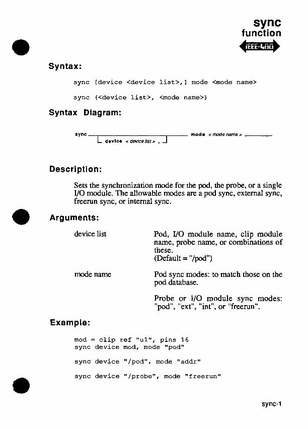
sync function
Syntax:
sync [device <device l i s t>,] mode <mode name>
sync (<device l ist>, <mode name>)
Syntax Diagram:
sync mod a < mode name r L devlca <devicelist> , J
Description:
Sets the synchronization mode for the pod, the probe, or a single VO module. The allowable modes are a pod sync, external sync, freerun sync, or internal sync.
@ Arguments:
device list
mode name
Pod, VO module name, clip module name, probe name, or combinations of these. (Default = "/podM)
Pod sync modes: to match those on the pod database.
Probe or I/O module sync modes: "pod", "ext", "int", or "freerun".
Example:
mod = c l i p r e f "ul" , p i n s 1 6 sync dev ice mod, mode "pod"
sync dev ice "/podw, mode "addr"
sync dev ice " /probew, mode " f reerun"

sync
Remarks:
When using the "pod" mode for the sync command, you must tell the pod what kind of pod sync signal should be generated. This is done with a second sync command:
sync device "/probe", mode "pod" sync device "/pod", mode "data"
Four 110 module or probe sync modes are allowed: external sync, pod sync, freerun sync, and internal sync.
External Sync Mode
This mode qualifies the external Clock line with the external measurement control Start, Stop, and Enable lines. For the probe, the lines are available through the clock module. The UO module has its own measurement control lines.
Start, Stop, and Clock are edge-sensitive inputs from the UUT. Each can be made to respond to falling or rising edges. The sync period can also be programmed to end after a specified number of valid clock pulses, in which case the Stop input is ignored. Enable is a level-sensitive signal and can be specified by the enable command.
After an ann command is entered, and after a valid Start edge is detected, the sync measurement period begins. Start is recognized independently of the enabling condition, but data is only gathered after the enabling condition becomes true. Asynchronous data is gathered immediately after this point. Synchronous data is gathered after the same point but only at the selected clock edges.
The data gathering period ends when the Stop condition becomes true: the selected Stop edge occurs, or a programmed number of clock edges completes. The data-gathering period ends when a readout command is executed.
In addition, this synchronization mode can be used to synchronize the probe's pulsing output resulting from the pulser command.

sync
Pod Sync Mode
This mode uses Pod Sync, an internal pod signal, as the clock. The generation of Pod Sync can be made to depend on valid address, data, or other (pod-dependent) cycles. The external measurement control lines are ignored.
Data is gathered after an arm command until a readout command is executed.
In addition, this synchronization mode can be used to synchronize the probe's pulsing output resulting from the pulser command.
Freerun Sync Mode
In this mode, the probe uses the 9100A/9105A system's internal lk Hz clock for asynchronous output. The external Start, Stop, Clock, and Enable lines are ignored.
For both the UO modules and the probe, asynchronous level history and transition count data can be gathered between the arm and readout commands. CRC signatures and clocked level histories are not gathered.
In addition, this synchronous mode can be used to synchronize the probe's pulsing output resulting from the pulser command.
Internal Sync Mode
This sync mode is designed to use a clock signal generated internally be the strobeclock command. The external measurement control lines (Start, Stop, Clock, and Enable) are ignored.
In addition, this synchronous mode can be used to synchronize the probe's pulsing output resulting from the pulser command.

sync
Related Commands:
arm, checkstatus, connect, enable, readout, strobeclock
For More Information:
The "Overview of TLI1" section of the Programmer's Manual. The Fluke pod manual for the microprocessor you are using.

sysaddr function
Syntax:
sysaddr 0
Syntax Diagram:
sysaddr- ( )
Description:
Returns the last address written to or read from.
Returns:
The last address written to or read from.
Example:
lastaddr = sysaddr ( ) ! stores the last address ! written to or read from in ! the variable lastaddr .
write addr sysaddr 0 , data $34
Remarks:
The value returned by sysaddr is used as the default address for the next read or write initiated from the operator's keypad.
In some cases, the last address written to or read from does not update sysaddr.
sysaddr
Related Commands:
sysspace
For More Information:
The "Overview of TL/lU section of the Programmer's Manual.

sysdata function
Syntax:
sysda ta 0
Syntax Diagram:
sysdata - ( )
Description:
Returns the last data read or written.
Returns:
The last data read or written.
Example:
l a s t d a t a = sysda ta 0 ! s t o r e s t h e l a s t d a t a read ! i n t h e v a r i a b l e l a s t d a t a
w r i t e d a t a sysda ta 0 , addr next
Remarks:
The value returned by sysdata is used as the default data for the next read or write initiated from the operator's keypad.
In some cases, the last data written or read does not update sysdata.

svsdata
Related Commands:
sysspace
For More Information:
The "Overview of TL/lM section of the Programmer's Manual.
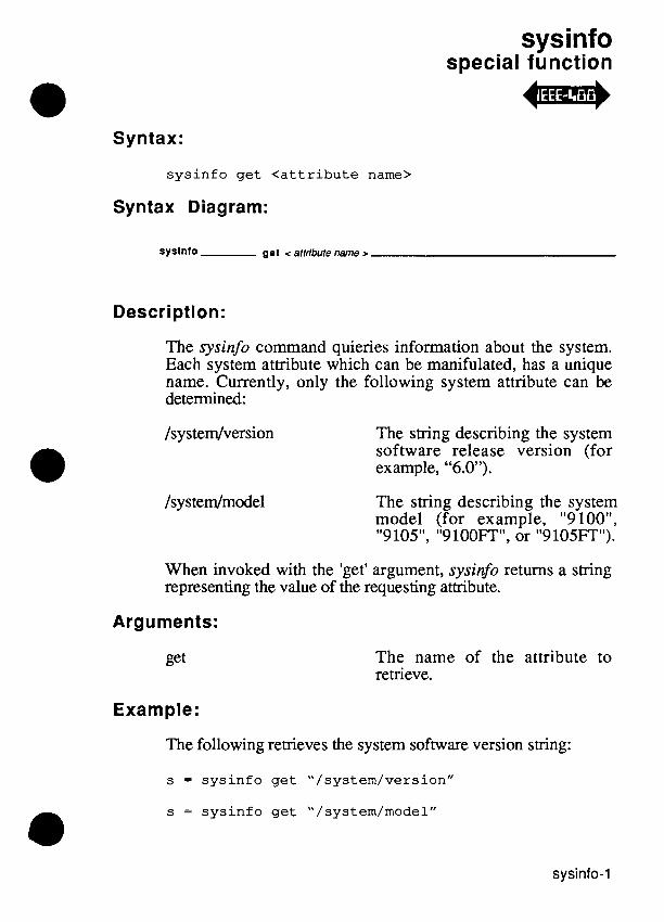
sysinfo special function
Syntax:
sysinfo get <attribute name>
Syntax Diagram:
syslnfo gel < attribute name >
Description:
The sysinfo command quieries information about the system. Each system attribute which can be manifulated, has a unique name. Currently, only the following system attribute can be determined:
The string describing the system software release version (for example, "6.0").
/sy s tedmodel The string describing the system model (for example, "9 loo", "9105", "9100FT", or "9105FT").
When invoked with the 'get' argument, sysinfo returns a string representing the value of the requesting attribute.
Arguments:
The name of the attribute to retrieve.
Example:
The following retrieves the system software version string:
s = sysinfo get "/system/version"
s = sysinfo get "/system/model"

sysinfo
Remarks:
This command first appeared in the 6.0 software release.
For More Information:
The "Overview of TL/l" section of the Programmer's Manual.

sysspace function
Syntax:
sysspace 0
Syntax Diagram:
sysspace - ( )
Description:
Returns the number associated with the last address space accessed.
Returns:
The number associated with the last address space accessed.
Examples:
program t e s t 1 5 s = ge t space space "memory", s i z e "byte" s e t s p a c e space s !
!
s 2 = sysspace 0 ! !
execute t e s t 1 2 ! !
s e t s p a c e space s 2 ! !
S e t s t h e add re s s space parameters .
Saves t h e l a s t - u s e d add re s s space parameters . Suppose t h e program t e s t 1 2 changes t h e add re s s space . Res to re s t h e o r i g i n a l add re s s space parameters .
end program

sysspace
Related Commands:
getspace, setspace, sysaddr, sysdata
For More Information:
The "Overview of TLI1" section of the Programmer's Manual.

systime function
Syntax:
systime 0
Syntax Diagram:
Description:
Returns the number of seconds that have elapsed since a particular date (January 1, 1980). This number alone is generally not useful. However, the difference between the numbers returned by two invocations of systime yields the elapsed time in seconds between the two invocations. The systime function also provides the argument for the readdate and readtime functions that produce the current date and time.
Returns:
The number of elapsed seconds.
Example:
start = systime ( )
testramfull addr 0, upto $7FFF finish = systime ( ) print "Full RAM test took ", finish - start,
I' seconds"
! prints: "Full RAM test took 368 seconds" ! if, testramfull requires six minutes and ! eight seconds to execute

systime
Related Commands:
readdate, readn'me
For More Information:
The "Overview of TLI1" section of the Programmer's Manual.

tan function
Syntax:
tan angle <expression>
tan (<expression>)
Syntax Diagram:
tan angle < expressh D
Description:
Returns the tangent function of a floating-point argument value.
Argument:
expression The argument (floating-point) value in radians.
Returns:
A floating-point number.
Examples:
f = tan ( (natural pi) / 4 . 0 ) f = tan angle theta
Related Commands:

tan

testbus function
Syntax:
testbus addr <address>
testbus (<address>)
Syntax Diagram:
testbus - addr <address z
Description:
Checks the address, data, and control lines for drivability.
address Readablelwritable address used for data bus testing.
Example:
testbus addr SFFFF
Remarks:
The testbus test performs the following checks:
Tests for control-line drivability.
Tests for address drivability and tied address lines.
Tests for data drivability and tied data lines.
The specified address must be a RAM location to prevent erroneous data line faults from being reported.

testbus
It is not a good idea to use testbus as a stimulus in GFI. The algorithm for this functional test could change and this would also change any resulting signatures. The commands toggleaddr, toggledata, rampaddr, and rampdata should be used instead.
Related Commands:
fails, passes
For More Information:
The "Overview of TL11" section of the Programmer's Manual.

testramfast function
Syntax:
testramfast addr <addr>, upto <upto> [, mask <mask>], addrstep <addrstep> [, delay <delay>] [, seed <seed>]
testramfast (<addr>, <upto>, <mask>, <addrstep>, <delay>, <seed>)
Syntax Diagram:
testramfast , addr < addf > , upto < uplo> ... L , mask < mask > -1
... , , addrstep<addrstep> ... L , delay <delay > A
Description:
Performs a probabilistic test on RAM.
Arguments:
addr Starting address.
upto
mask
addrstep
delay
Ending address.
Bit mask of testable data bits. (Default = $FFFFFFFF)
Address increment.
Milliseconds to delay between sweeps. (Default = 250)

testramfast
seed Number to be used as seed for pseudo- random number generator. (Default = 0; seed based on real-time clock.)
Example 1:
testramfast addr $B, upto here, addrstep 2 ! address hex B to address in variable ! "here"
Example 2:
testramfast addr $1234, upto $12FE, mask $7F, addrstep 2
! only the lower 7 data bits are tested
Remarks:
The fast RAM test is a probabilistic test which has complete coverage of a wide range of common faults and very thorough coverage of nearly every possible RAM fault. Each word is accessed five times using pseudo-random data.
The coverage of testramfast is shown on the next page. "P" represents the probability that a fault is not detected. "K" represents the number of addresses affected by the fault. The values which appear in parentheses are the actual probabilities for a 16K memory. Larger memories have better fault coverage.

testramfast
testrarrgfast Coverage
Fault Condition
Stuck cells
Aliased cells
Stuck address lines
Stuck data lines
Shorted address lines
Shorted data lines
Multiple selection decoder
Dynamic coupling
Aliasing between bits in same word
Refresh problems
Pattern sensitive faults
Coverage
Always found.
Always found.
Always found.
Always found.
Always found.
P = 0 .5~ .
P = O S K (2.9 x for a row or column decoder.
P = 0 . 7 5 ~ (0.75 for 1 cell coupling to 1 other cell).
P = 0SK.
Always detected if the delay is sufficiently long and standby reads do not mask the problem.
Because of the random nature of this test, some pattern sensitive faults can be detected.
The seed parameter controls the exact sequence of pseudo- random values which are generated. When the seed argument is zero, the 9100A19105A generates a different sequence of pseudo-random data at each pass through the memory. You should specify zero in most applications.
The mask parameter provides a convenient method for testing the parity bit of memories so equipped. First you perform a testramfast test with a mask that tests all valid data bits. Then you do a second testramfast test, but use a mask with an odd number of bits set. In addition, this second test is done with a line of a clip module connected to the output of the memory parity tree. The DCE condition is generated by using a compare
testramfast
command with a compare string only one bit long, which checks for the desired logic level at the parity tree output.
The procedure for testing memories with error-correcting codes is similar, except that you should choose a mask such that toggling the bits specified by the mask will cause all the check bits to toggle.
Related Commands:
fails, passes, testramfill
For More Information:
The "Overview of TLI1" section of the Programmer's Manual.
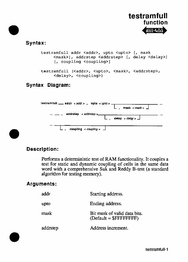
testramfull function +m*
Syntax:
testramfull addr <addr>, upto <upto> [, mask <mask>], addrstep <addrstep> [, delay <delay>] [, coupling <coupling>]
testramfull (<addr>, <upto>, <mask>, <addrstep>, <delay>, <coupling>)
Syntax Diagram:
testramfull - addr <addr> , upto < upror ... L , mask <mask> J
... - , addrstep t addrsrep> ... L , delay < d e l a y r A
L , coup~ng < coupling r -I
Description:
Performs a deterministic test of RAM functionality. It couples a test for static and dynamic coupling of cells in the same data word with a comprehensive Suk and Reddy B-test (a standard algorithm for testing memory).
Arguments:
addr
mask
addrstep
Starting address.
Ending address.
Bit mask of valid data bits. (Default = $FFFFFFFF)
Address increment.

testramfull
delay Milliseconds to delay between sweeps. (Default = 250)
coupling "ont' or "off'. (Default = "off ')
Example 1:
testramfull addr $B, upto here, addrstep 2 ! address hex B to variable address "here"
Example 2:
testramfull addr $1234, upto $13FF, mask $ 7 ~ , addrstep 2
Remarks:
The full RAM test is a deterministic test of RAM functionality. With coupling disabled, each word is accessed 17 times. With coupling enabled, each word is accessed 29 times for 8-bit spaces, 33 times for 16-bit spaces, and 37 times for 32-bit spaces.
This test has been found to be superior to testramfast in finding faults caused by electrical transients in the bus where worst-case fault detection occurs when writing data with all ones or all zeros. Fault coverage for testramfill is shown on the next page.

testramfull
testran3full Coverage
Fault Condition
Stuck cells
Aliased cells
Stuck address lines
Stuck data lines
Shorted address lines
Shorted address lines
Multiple selection decoder
Dynamic coupling
Aliasing between bits in same word
Refresh problems
Pattern sensitive faults
Coverage
Always found.
Always found.
Always found.
Always found.
Always found.
Always found if coupling is enabled or in buses through which the first or last address must pass.
Always found.
Always found.
Always found if coupling is enabled.
Always found if delay is sufficiently long and standby reads do not mask the problem.
Not found.
The delay parameter specifies the amount of time that the test waits between sweeps. This delay can be increased to find faults related to the dynamic memory refresh circuit.
The mask parameter provides a convenient method for testing the parity bit of memories so equipped. First you perform a testramfull test with a mask that tests all valid data bits. Then you do a second testramfull test, but use a mask with an odd number of bits set. In addition, this second test is done with a line of a clip module connected to the output of the memory parity tree. The DCE condition is generated by using a compare command with a compare string only one bit long, which checks for the desired logic level at the parity tree output.

testramfull
The procedure for testing memories with error-correcting codes is similar, except that you should choose a mask such that toggling the bits specified by the mask will cause all the check bits to toggle.
The coupling test verifies that, for every word, each pair of bits in that word can store opposite values. For many memory systems, the coupling test will not be necessary since the pretest checks for this with the first and last addresses, even with coupling disabled. However, for some memory systems, enabled coupling will be required in order to have a fully conclusive test.
You can specify an exhaustive check for coupling between bits in the same word (shorted data bus lines manifest as this fault at every address) by enabling coupling. For an eight-bit space the values 55, AA, 33, CC, OF, and FO are written to every word and read back. Wider spaces are similar.
Related Commands:
fails, passes, testramfast
For More Information:
The "Overview of TL11" section of the Programmer's Manual.

testromfull function 4m*
Syntax:
testromfull addr <addr>, upto <upto> [, mask <mask>], addrstep <addrstep>, sig <expsig>
testromfull (<addr>, <upto>, <mask>, <addrstep>, <expsig>)
Syntax Diagram:
testromlull- addr < addrr , upto < uptor ... L , mask <mask r J
. . . , , addrstep < addrstep r - , slg < expsig r
Description:
Verifies that the signature data contained by a range of ROM matches the signature obtained from a c 0 ~ e c t . 1 ~ programmed ROM.
Arguments:
addr Starting address.
upto
mask
Ending address.
Bit mask of valid data bits. (Default = $FFFFFFFF)
addrstep Address increment.
expsig Expected signature.
Example 1:
testromfull addr 0, upto $7FF, addrstep 1, sig $BE26
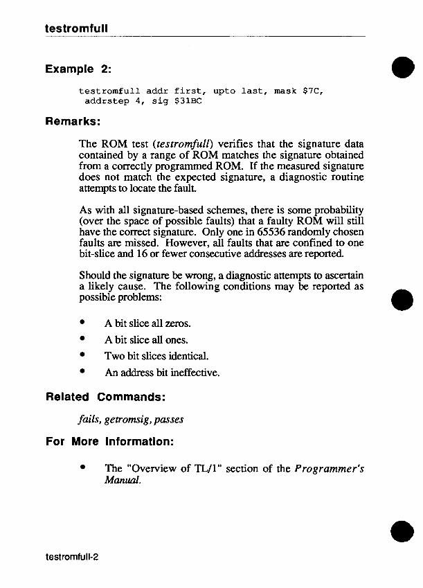
testromfull
Example 2:
testromfull addr first, upto last, mask $7C, addrstep 4, sig $31BC
Remarks:
The ROM test (testromfull) verifies that the signature data contained by a range of ROM matches the signature obtained from a correctly programmed ROM. If the measured signature does not match the expected signature, a diagnostic routine attempts to locate the fault.
As with all signature-based schemes, there is some probability (over the space of possible faults) that a faulty ROM will still have the correct signature. Only one in 65536 randomly chosen faults are missed. However, all faults that are confined to one bit-slice and 16 or fewer consecutive addresses are reported.
Should the signature be wrong, a diagnostic attempts to ascertain a likely cause. The following conditions may be reported as possible problems:
A bit slice all zeros.
A bit slice all ones.
Two bit slices identical.
An address bit ineffective.
Related Commands:
fails, getromsig , passes
For More Information:
The "Overview of TL/lW section of the Programmer's Manual.

threshold function 4-a
Syntax:
t h r e s h o l d [device <device l i s t > ] [, l e v e l < l e v e l name>]
t h r e s h o l d (<device l i s t> , < l e v e l name>)
t h r e s h o l d ( )
Syntax Diagram:
threshold dovlco < devfce //st z
Iovol <levelnamer IF0 4' Description:
Sets the input threshold levels for the probe or an VO module. The allowable levels are "ttl", "cmos", or (for the probe only) "rs232". "ecl" is allowed for the probe if ecl capability is installed.
Arguments:
device list
level name
VO module name, clip module name, probe name, or combinations of these. (Default = "/probew)
VO module threshold levels "ttl" or "cmosI'.
Probe threshold levels: "ttl", "cmos", or "rs232" if ecl capability is not installed.

threshold
Probe threshold levels: "ttl", "cmos", "rs232", or "ecl" if ecl capability installed.
Example 1:
mod = c l i p device "a l" , p ins 2 4 t h r e s h o l d device mod, l e v e l "ttl"
Example 2
t h r e s h o l d ("/modl", "ttl")
For More Information:
The "Overview of TLI1" section of the Programmer's Manual.

toggleaddr function
Syntax:
toggleaddr addr <address>, mask <mask>
toggleaddr (<address>, <mask>)
Syntax Diagram:
toggleaddr - addr <address> , mask <mask>
Description:
Performs a series of read functions to stimulate the microprocessor's address bus. For each 1 in the mask, two accesses are performed: one at the address with the masked bit set and one at the address with the masked bit cleared.
Arguments:
address Address.
mask Bit mask of address bits to toggle.
Example:
toggleaddr addr $1004, mask $25 ! addr 1 0 0 4 hex = 0 0 0 1 0000 0000 0100 ! mask 2 5 hex = 0000 0000 0010 0 1 0 1

toggleaddr
The system performs a series of six reauk as shown below:
read addr $1004 read addr $1005
read addr $1004 read addr $1000
read addr $1004 read addr $1024
Remarks:
Accesses are made in pairs for each bit in the mask, first at the original address and then at the address with the bit toggled.
The number of read's is equal to twice the number of bits set in the mask. The data read is not returned.
A 9000-series toggle address (ATOG) performs the equivalent of a toggleaddr for a single bit. Therefore, the following pairs of commands are equivalent:
toggleaddr addr $100, mask 1 ATOG @ 100 Bit 0 toggleaddr addr $100, mask $10 ATOG @ 100 Bit 4
For More Information:
The "Overview of TLI1" section of the Programmer's Manual.

togglecontrol function
Syntax:
t o g g l e c o n t r o l c t l < c o n t r o l word>, mask <mask>
t o g g l e c o n t r o l ( < c o n t r o l word>, <mask>)
Syntax Diagram:
togglecontrol - ctl < mtroi w r d > , mask <mask >
Description:
Performs a series of writecontrols to stimulate the microprocessor's control bus. For each 1 in the mask, two writecontrols are performed: one with the masked bit set, and one with the masked bit cleared.
Arguments:
control word Control word.
mask Mask of control bits to toggle.
Example:
t o g g l e c o n t r o l c t l 1, mask $41
The system performs two pairs of writeconrrols:
w r i t e c o n t r o l c t l 1 w r i t e c o n t r o l c t l 0
w r i t e c o n t r o l c t l 1 w r i t e c o n t r o l c t l $41

togglecontrol
Remarks:
Writes are performed in pairs for each bit in the mask, first with the original control word and then with the toggled value.
For More Information:
The "Overview of TL/ln section of the Programmer's Manual.

toggledata function 44mp
Syntax:
toggledata addr < a d d r > , da ta < d a t a > , m a s k < m a s k >
toggledata ( < a d d r > , < d a t a > , < m a s k > )
Syntax Diagram:
toggledata - addr <address> , data <data> , mask <mask> -
Description:
Performs a series of writes to stimulate the microprocessor's data bus. For each 1 in the mask, two writes are performed: one with the masked data bit set and one with the masked data
addr Address.
data Data value.
mask Mask of bits to toggle.
Examples:
toggledata addr SEEDO, da ta SAA, m a s k $ 5 5
The system performs:
w r i t e addr SEEDO, data $AA w r i t e addr SEEDO, data $AB
w r i t e addr SEEDO, data $AA w r i t e addr SEEDO, data $AE
( e x a m p l e i s con t inued on t h e next page)

toggledata
write addr SEEDO, data $AA write addr SEEDO, data $BA
write addr SEEDO, data $AA write addr SEEDO, data SEA
Remarks:
Writes are performed in pairs for each bit in the mask, first with the original data and then with the toggled data.
For More Information:
The "Overview of TL/lN section of the Programmer's Manual.

token function
Syntax:
t o k e n s t r < s t r i n g > [ , s e p s < s e p a r a t o r s > [ , f rom < s t a r t index> ]
t o k e n ( < s t r i n g > , <seps> , < s t a r t index>)
Syntax Diagram:
token 6tr c string r . . . , rep6 c separators r
. . . , from c start index r
Description:
Implements token scanning from strings, where the tokens can be distinguished by the presence of one or more separator characters.
Arguments:
string
separators
The string expression that is being scanned for a token.
A string containing the set of separator characters that can separate token values. Each character in the set is considered equivalent to all other characters in the set. No character fiom the separator set is included in any returned token sting value. The default set of separator characters is (newline, linefeed, space, tab).

token
start index The index in the string to start scanning for the next token substring, where an index value of 1 corresponds to the first character in the string. If the start index is not supplied, scanning starts at the beginning of the string unless the previous call to the token command supplied the same string argument. In that case, scanning continues at the position in the string immediately following the last returned token.
Returns:
The next and largest possible substring from the source string that does not contain any characters from the set of separators, skipping over any initial separator prefix sequence. If there are no more substrings that do not contain non-separator characters, then an empty string is returned.
Examples:
Given an arbitrary input string in-string, extract the "words" (where a word is any non-white- space sequence of characters), assigning up to 10 words to the elements of a string array:
declare string array [1:10] words ! extract the first word next-word = token str in-string, from 1 i = l loop while (next-word <> "" )
if (i <= 10) then words [i] = next-word
! extract the next word next-word = token str in-string
else next-word = ""
end if
i = i + l end loop

token
Suppose an IEEE-488 device outputs a single floating-point number string value, with an arbitrary number of leading spaces and a carriage return, linefeed character sequence a f g e a c h value. The following program example strips the whitespace (the spaces, carriage return and linefeed), then converts the remaining string to a floating-point number. If the device is opened with the termination character of the channel set to lihefeed, the problem reduces to stripping the spaces and the carriage return:
declare numeric ieee-chan declare numeric term-chan declare string val-string declare floating val-number
term-chan = open device "/termlm ieee-chan = open device "/ieee/lW,. term "\OAW print on ieee-chan, "val?" input on ieee-chan, val-st ring val-string = token str val-string, from 1 ! strip whitespace if (isflt (val-string) ) then
val-number = fval (val-string) print on term-chan, "value is ", val-number
else print on term-chan, "received a bogus value: ", val-string
end if
Suppose an IEEE-488 device outputs analog measurements in the following format:
chan (<nn>) : <ss> <f f f f . . . >
where <nn> represents a "channel number" in radix 10, <ss> represents a measurement status in radix 16, and <ffff. ..> is a string representation of the floating-point measurement value.
The following TL/1 fragment extracts these various fields, given the initial input string in the string variable meas-string:
meas-seps = " 0 : " ! the set of separators ! skip the "chan" substring token (meas-string, meas-seps, 1)

token
! extract the channel number chan-string = token str meas-string, seps meas-seps
if (isval (chan-string, 10) ) then chan-num = val(chan-string, 10)
else ! measurement string syntax error ! detected return (0)
endif
! extract the measurement status status-string = token str meas-string, seps meas-seps
if (isval (status-string, 16) ) then meas-status = val (status-string, 16)
else' !measurement string syntax error !detected return (0)
endi f
! extract the measurement value value-string = token str meas-string, seps meas-seps
if (isflt (value-string) ) then meas-value = fval(va1ue-string)
else ! measurement string syntax error ! detected return (0)
endif
Remarks:
The token command is useful for separating the fields of an input string from one another. Given a particular input smng, token can be called repeatedly to extract the fields of the smng.
Related Commands:
isval, isjlt

val function
Syntax:
val str <string> [, radix <radix>] val (<string>, <radix>)
Syntax Diagram:
val str <string >
L , radix <radix> 1
Description:
Calculates the numeric value of the string operand using the specified radix.
Arguments:
smng
radix
A smng which represents a number.
A numeric expression for the radix to use for the returned number. Allowed values for radix are 2, 8, 10 (default), and 16.
Returns:
A numeric value.
Example:
x = val ("15",16) ! the variable x is set to ! the numeric value of ! hexadecimal 15
x = val ("15",10) ! the variable x is set to ! the numeric value of decimal 15

Related Commands:
pal, str, isval

wait function
Syntax:
wait time <expression>
wait (<expression>)
Syntax Diagram:
walt t l me < expression r
Description:
Causes program execution to pause for the specified number of milliseconds.
Argument:
expression
Example:
Approximate length of time in milliseconds.
wait time 1000 ! Generate a one-second pause (plus or ! minus about 50 milliseconds)

wait
Remarks:
You must use wait commands carefully since they can cause a program to pause indefinitely. The wait command cannot be used to generate exact timing. The precision of the timer is approximately 50 milliseconds; longer waits may result if the 9 100Al9 lO5A must service interrupts or perform other operations.
For More Information:
The "Overview of TL11" section of the Programmer's Manual.

waituut function
Syntax:
wai tuut maxtime <express ion>
wai tuu t (<express ion>)
Syntax Diagram:
waltuut - rnaxtlrne c expression >
Description:
Suspends TL/1 program execution until one of the following conditions occurs:
The pod encounters a breakpoint.
The DCE condition occurs.
The number of milliseconds specified by the expression expires.
Argument:
expression
Example:
A numeric expression for the maximum timeout limit value in milliseconds.
runuut addr SFFOO wai tuu t maxtime 4000 ! suspends TL/1 program
! execut ion f o r 4 seconds ! whi le t h e UUT i s c o n t r o l l e d ! by i t s own program

waituut
Remarks:
After executing runuut, you must invoke either haltuut or waituut to regain control of the pod before executing other statements that send commands to the pod.
The command waituut (0) is equivalent to haltuut 0.
The waituut command is usually preferred over continuous looping using polluut because it frees the 9100A/9105A processor for other functions.
Related Commands:
haltuut, polluut, runuul
For More Information:
The "Overview of TL/1 " section of the Programmer's Manual.

winctl function
Syntax:
w i n c t l channel <channel express ion>, p o s i t i o n < p o s i t ion>
Syntax Diagram:
wlnctl - channel < channel expression > - , posltlon < pmi~m > -
Description:
Controls the window position for the specified channel.
Arguments:
channel expression A numeric exmession to define a channel openedLto write on the desired window. Remember that /term1 and /term2 are also considered windows.
position The position is one of the following:
"front" The window covers all other windows.
"back" The window is covered by all other windows.
"hide" The window is invisible.
"unhide" The window becomes visible.

winctl
Example 1:
w i n c t l channel chanl , p o s i t i o n " f r o n t "
Example 2:
w i n c t l channel chan2, p o s i t i o n "hide"
Remarks:
A window in the front covers all other windows. A window in the back is covered by all other windows. A window when hidden becomes invisible, but remains in the same position on the screen.
Related Commands:
open
For More Information:
"The Overview of TL/1" section of the Programmer's Manual.

write function
Syntax:
write addr <address>, data <data>
write (<address>, <data>)
Syntax Diagram:
w r l t e addr <address> , data <data>
Description:
Writes the specifkd data to the specified address.
Arguments:
address Address at which to write.
data Data to write.
Examples:
write addr $5567, data $21 ! writes hex 21 at ! hex address 5567
write data $34, addr $CDD3FF ! writes hex 34 ! at hex address ! CDD3FF

write
Remarks:
Refer to the pod manual for the microprocessor you are using to find specific address and data formats.
For More Information:
The "Overview of TL11" section of the Programmer's Manwl.

writeblock function 4m*
Syntax:
writeblock file <file name> [, format <format name>]
writeblock (<file name>, <format name>)
Syntax Diagram:
wrlteblock - flla <filename r L , format < rtxmarname r J
Description:
Loads the contents of a file in a standard ASCII form (Motorola S-Record format or Intel Hex format) into UUT or pod overlay RAM. The file contains information about the starting address and number of data bytes.
Arguments:
file name The name of the file containing the required data.
format name The ASCII format in which the data was previously stored. Either "motorola" or "intel". (Default = "motorola".)
Examples:
writeblock file "test-lcd", format "motorola"
writeblock ("pgml", "motorola")

writeblock
Related Commands:
loadblock, readblock
For More Information:
The "Overview of TL/1 " section of the Programmer's Manual.
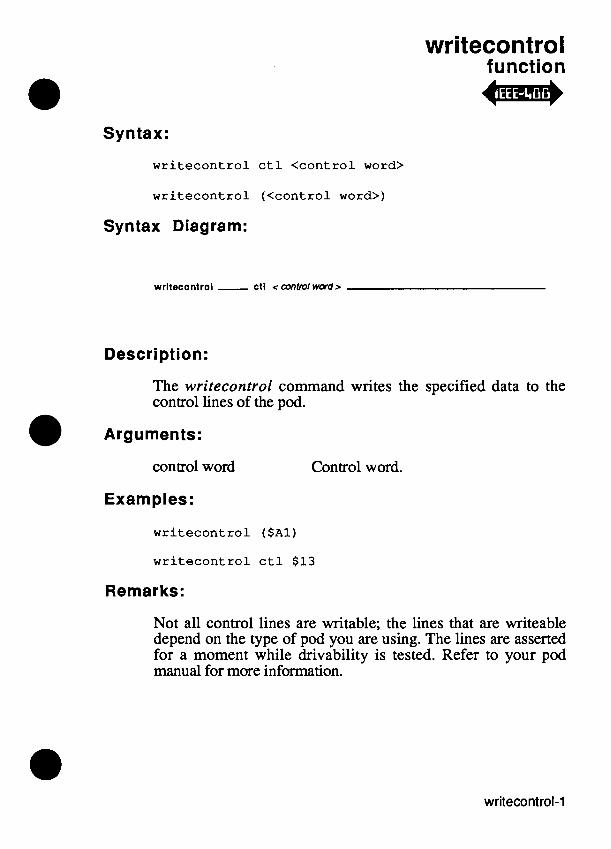
writecontrol function 4 j *
Syntax:
w r i t e c o n t r o l c t l < c o n t r o l word>
w r i t e c o n t r o l ( < c o n t r o l word>)
Syntax Diagram:
wrltetontrol - ctl <control wwdr
Description:
The writecontrol command writes the specified data to the control lines of the pod.
Arguments:
control word Control word.
Examples:
w r i t e c o n t r o l ($Al)
w r i t e c o n t r o l c t l $13
Remarks:
Not all control lines are writable; the lines that are writeable depend on the type of pod you are using. The lines are asserted for a moment while drivability is tested. Refer to your pod manual for more information.

writecontrol
Related Commands:
For More Information:
The "Overview of TL11" section of the Programmer's Manual. The Fluke pod manual for the rni~~~processor you are using.

writefill function -
Syntax:
writefill addr <address 1>, upto <address 2>, data <data>
writefill (<address 1>, <address 2>, <data>)
Syntax Diagram:
wrlteflll - addr <address 1 > , upto <address2> , data <data > -
Description:
The writejill command writes the specified data to each address within the specified address range.
Arguments:
address 1 Starting Address.
address 2 Ending Address.
data Data value.
Examples:
writefill addr $1000, upto $1FFF, data $21
writefill (0, $7F, S123D567E)
For More Information:
The "Overview of TL/l" section of the Programmer's Manual.

writefill
writef ill-2

writepatt function
Syntax:
w r i t e p a t t [device < d e v i c e l is t>] [, m o d e < m o d e n a m e > ]
w r i t e p a t t ( < d e v i c e l ist>, < m o d e n a m e > )
w r i t e p a t t ( )
Syntax Diagram:
wrltopatt dovlco < device l l s r ~ mode <modename>
a Description:
Overdrives the specified sequence of patterns through the VO module. The pattern to be written to each pin is stored beforehand using the storepatt command.
Arguments:
device list
mode name
VO module name, clip module name, reference designator, or combinations of these. (Default = "/mod1 ")
"pulse", or "latch". (Default = "latch")

writepatt
Example:
! dr iv ing a 7400 through i t s t r u t h t a b l e :
mod = c l i p re f " U l , p ins 1 4 c l e a r p a t t device "U1" s t o r e p a t t device "U1" , pin 1, p a t t "0011" s t o r e p a t t device " U l " , pin 2, p a t t "0101" s t o r e p a t t device "Ul" , p in 4, p a t t "0011" s t o r e p a t t device "Ul" , p in 5, p a t t "0101" s t o r e p a t t device "Ul" , p in 9, p a t t "0011" s t o r e p a t t device "U1" , pin 1 0 , p a t t "0101" s t o r e p a t t device " U l " , pin 12, p a t t "0011" s t o r e p a t t device " U l " , p i n 13, p a t t "0101"
! i n t e r n a l sync mode required f o r wr i t epa t t sync device mod, mode " in t " arm device mod
wr i t epa t t device "Ul" , mode " la tch" readout device mod
Remarks:
The writepatt command requires that the sync mode be set to "int".
The maximum pattern depth for writepatt for each pin depends on the number of UO modules used:
Number of UO Maximum Pattern Modules Used Depth
Appendix E, "YO Module Clip/Pin Mapping," shows, for each clip module, which I/O module pin is connected to each clip pin.

writepatt
Related Commands:
storepatt, clearpatt, clearoutputs
For More Information:
The "Overview of TLI1" section of the Programmer's Manual.

writepatt

writepin function
Syntax:
writepin [device <device name>] [, p i n <pin number>] [, l e v e l < l e v e l > ] [, mode <mode>] [, re fp in <re fp in name>]
writepin (<device name>, <pin number>, < l e v e l > , <mode>, <re fp in name>)
wri tepin ( )
Syntax Diagram:
wrltepln dovlco < device name > pln <pinnumber> lovol <level>
rofpln < relpin name >
Description:
Sets the specified I/O module pin to the desired state by either latching or pulsing.
Arguments:
device name
pin number
level
I/O module name, clip module name, or reference designator. (Default = "/mod1 ")
I/O module pin number. (Default = 1)
"1" for high, "0" for low, and "X" or "x" for high-impedance. (Default = "0")
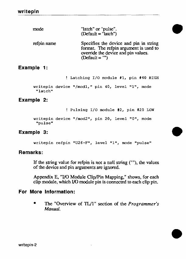
writepin
mode "latch" or "pulse". (Default = "latch")
refpin name Specifies the device and pin in string format. The refpin argument is used to ovemde the device and pin values. (Default = "")
Example 1:
! L a t c h i n g I / O module #1, p i n #40 H I G H
w r i t e p i n d e v i c e "/modl, " p i n 40, l e v e l "I", mode " l a t c h "
Example 2:
! P u l s i n g I / O module #2, p i n #20 LOW
w r i t e p i n d e v i c e "/mod2", p i n 20, l e v e l " O w , mode " p u l s e "
Example 3:
w r i t e p i n r e f p i n "U26-F", l e v e l "I", mode " p u l s e "
Remarks:
If the string value for refpin is not a null string (""), the values of the device and pin arguments are ignored.
Appendix E, "UO Module ClipIPin Mapping," shows, for each clip module, which UO module pin is connected to each clip pin.
For More Information:
The "Overview of TL11" section of the Programmer's Manual.

writespecial function 4i..n4
Syntax:
writespecial addr <address>, data <data>
writespecial (<address>, <data>)
Syntax Diagram:
wrltespeclal - addr <address> , data <data>
Description:
Writes the specified data to the specified virtual address. This allows access to the virtual addresses that, in some pods, are used for special operations. This command should only be used when you know that the normal write command does not provide the required special operation.
Arguments:
address The virtual address where data will be written.
data Data to write.
Examples:
writespecial addr $F0000018, data $21
For More Information:
The "Overview of TL11" section of the Programmer's Manual. The Fluke pod manual for the microprocessor you are using.

writespecial

writevirtual function *m*
Syntax:
writevirtual extaddr <ext>, addr <address>, data <data>
writevirtual (<ext>, <address>, <data>)
Syntax Diagram:
mltovlrtual - oxtaddr < ext r - . - addr <address r , data < data r .-,
Description:
Writevirtual is a complete replacement for the obsoleted writespecial command. The writevirtual command writes the specified data to the specified virtual address. This allows access to the virtual addresses that, in some pods, are used for special operations. This command should only be used when you know that the normal write command does not provide the required special operation.
Arguments:
extaddr Extended address bits.
address The virtual address where data will be written.
data Data to write.
Examples:
writevirtual extaddr 0, addr $F0000018, data $21

writevirtual
For More Information:
The "Overview of TL11" section of the Programmer's Manual. The Fluke pod manual for the microprocessor you are using.

writeword function
Syntax:
w r i t e w o r d [ d e v i c e < I / O m o d u l e n a m e > ] [ , w o r d < w o r d number>] [ , p a t t <pattern>]
w r i t e w o r d (<1 /0 m o d u l e n a m e > , <pat tern> , < w o r d number>)
Syntax Diagram:
Description:
Writes a data pattern to a group of UO module pins. The group of UO module pins is set using senuord.
Arguments:
UO module name UO module name ("/mod 1 ", " / m d " , ''/mod3 It, or "/mod4"). (Default = "/mod1 ")
word number This specifies the pin grouping to use in writing out the word. (Default = 1)
pattern
Example 1:
Specifies the levels to be driven. Valid values are 1 (HIGH), 0 (LOW), and X or x (driver off, 3-stated) (Default = "0")
w r i t e w o r d device " / m o d l " , w o r d 4, p a t t "10X"

writeword
Example 2:
writeword device "/mod2", word 1, patt "000000000000"
Remarks:
If not enough levels have been specified in the pattern, they are assumed to be LOW. If too many values are specified, the leading values are ignored.
Related Commands:
readword, setword
For More Information:
The "Overview of TL/lM section of the Programmer's Manual.

Appendix A ASCII - Codes

CHR HEX DEC CHR HEX DEC CHR HEX DEC CHR HEX DEC
NUL SOH STX ETX EOT ENQ ACK BEL B S HT LF VT F F CR SO S I D LE DC 1 DC2 DC 3 DC 4 NAK SYN ETB CAN EM SUB ESC F S GS RS us
@ 40 6 4 60 9 6 A 4 1 6 5 a 6 1 9 7 B 42 6 6 b 6 2 9 8 C 4 3 6 7 c 6 3 9 9 D 4 4 6 8 d 6 4 1 0 0 E 4 5 6 9 e 6 5 1 0 1 F 4 6 7 0 f 6 6 1 0 2 G 4 7 7 1 g 6 7 1 0 3 H 4 8 7 2 h 6 8 1 0 4 I 4 9 7 3 i 6 9 1 0 5 J 4A 7 4 j 6A 1 0 6 K 4B 7 5 k 6B 1 0 7 L 4C 7 6 1 6C 1 0 8 M 4D 7 7 m 6D 1 0 9 N 4E 7 8 n 6E 1 1 0 0 4 F 7 9 o 6 F 111 P 5 0 8 0 p 7 0 1 1 2 Q 51 8 1 q 7 1 113 R 5 2 8 2 r 7 2 1 1 4 S 53 8 3 s 7 3 115 T 5 4 8 4 t 7 4 1 1 6 U 55 8 5 u 7 5 1 1 7 V 5 6 8 6 v 7 6 1 1 8 W 5 7 8 7 w 7 7 1 1 9 X 5 8 8 8 x 7 8 1 2 0 Y 5 9 8 9 y 7 9 1 2 1 Z 5A 9 0 z 7A 1 2 2 [ 5 B 9 1 ( 7B 1 2 3 \ 5C 9 2 I 7C 1 2 4 ] 5D 9 3 ) 7D 1 2 5 A 5E 9 4 - 7 E 1 2 6
- 5 F 9 5 RUB 7 F 1 2 7

@ Appendix B Control Codes for Monitor
and Operator's Display
ERASING B.1.
Cursor to end-of-line ESC [ K or ESC [ 0 K
Beginning-of-line to cursor ESC [ 1 K Line containing cursor ESC [ 2 K Cursor to end-of-screen ESC [ J
or ESC [ 0 J Beginning-of-screen to cursor ESC [ 1 J Entire screen ESC [ 2 J
NOTE
Since the ESC key cannot be entered from the keyboard, substitute a backslash followed by the ASCII code for the ESC character. The example below erases the entire screen:
p r i n t " \ 1 B [ 2 J W

CURSOR CONTROL SEQUENCES 8.2.
UP Down Right L e f t
D i r e c t c u r s o r add re s s ing ESC [ P1;Pc H Where P1 = l i n e number o r ESC [ P1;Pc f
and PC = column number
Index ESC D
Next l i n e ESC E
Reverse index ESC M
Save c u r s o r and a t t r i b u t e s ESC 7 Res tore c u r s o r and a t t r i b u t e s ESC 8
DISPLAY ATTRIBUTES 8.3.
Change d i s p l a y a t t r i b u t e s ESC [ Ps m
Where Ps = 0 ( A l l a t t r i b u t e s o f f ) 1 (Bold) * 4 (Underscore) * 5 (Bl ink) 7 ( ~ n v e r s e / ~ e v e r s e v ideo)
* Not a v a i l a b l e f o r t h e o p e r a t o r ' s d i s p l a y .
DISPLAY MODE SEQUENCES
I n s e r t mode enabled Replacement mode enabled
Auto Line-feed mode enabled Auto Line-feed mode d i s a b l e d
ESC [ 4 h ESC [ 4 1
ESC [ 20 h ESC [ 20 1

Auto Wrap mode enabled Auto Wrap mode d i s a b l e d
Text c u r s o r enabled Text c u r s o r d i s a b l e d
TAB STOPS
S e t a t c u r r e n t column C l e a r a t c u r r e n t column
C lea r a l l t a b s
EDITING CONTROL
I n s e r t l i n e D e l e t e l i n e In . se r t c h a r a c t e r s D e l e t e c h a r a c t e r s
ANNUNCIATOR CONTROL
Set Annunciators
Where Ps =
ESC [ ? 7 h ESC [ ? 7 1
ESC [ ? 25 h ESC [ ? 25 1
ESC [ Pn L ESC [ Pn M ESC [ Pn @ ESC [ Pn P
ESC [Ps q
0 (All Annunciators Off) 1 (Busy) 2 (Stopped) 3 (Storing Seq) 4 (More Softkeys) 5 (More Information) 6 (Alpha)
When control returns from TL/1 to the operator interface, the operator interface sets the annunciators back to the correct state.

BEEPER CONTROL
Set Beeper
Where P1=
and Pt =
length in milliseconds. The actual length is set in increments of 16 milliseconds with a maximum of 1.008 seconds.
0 Bell 1 1 Bell 2 (Default on
power up) 2 Bell 1 and Bell 2
Setting the beep tone from the operator interface restores the beeper to Bell 2.
SPECIAL DISPLAY CHARACTERS FOR THE OPERATOR'S DISPLAY B.9.
Two-digit IC pin numbers (in GFI displays) are displayed in single-character cells. The special codes for these two-digit numbers are generated by this formula:
number + 95hex.
For example, the number 23, as displayed below, would use the hex code AC.

Other special symbols used in displaying ICs on the operator's display are shown below.
Symbol Hex
I C H e a d I C B o d y I C U p p e r L e g I C L o w e r L e g I C L o n g U p p e r L e g I C L o n g L o w e r L e g U p A r r o w Down A r r o w ~ i d i r e c t i o n a l A r r o w eft-adjusted V e r t i c a l B a r
DISPLAY CHARACTERS FOR THE MONITOR B.10.
The 9100Al9105A may use either the Fluke monochrome monitor or a customer-supplied IBM-compatible color monitor. Both ASCII characters and special graphics characters may be displayed on either type of monitor. The following pages show the 9x10 pixel character cells used for monochrome display and the 9x9 pixel character cells used for color display. The number above each character represents the hexadecimal control code required to use the character.

Monochrome Font, ASCII Characters B.8.1. 28
i iMi mom mu m w 5 o 8888N88El mmmmo mmmmo mmmmo
30 38 40 48 50 58 m m q q mmm q mmm om m ommmm mmmmo
88~ff iB99 mm~mm ~ B M B ommmm S#MMEI ~~mwmmu El33!$!#10 mmmm 013MMB mclmmao EQWBi380 m~ommo wmmmo oommmm omommm 8mmmmmmo 8111111m mmm3mo B!MHJE ~l:mi~ i:aBm E~~~BHEI 0:mm maws mnmmmo oommm oommmo owommm omm m mmmom m m q o ommmm m[mpm ommmm ommHm mmmmo mmm o ommmm ommmm ommmm ommmm mmmmo
mmmmo bm m ommmm o&mm bmmmm Emmmo SeMM!?i El88@kl 83 !MM6€l 888888830 0BMBB6€l MMWB0 mmmmo mmmm ommmm ommmm omommmo mmommo mommmoo ommmm ommmm ommmm ommmmm mmmmo ffiEl8888El 888e58888 08888830 ElR88883i 03988888 B88!88880 m11111 0 ommmm ommm ommmm ommmm 011111110 mmmdo ommmm ommmm ommmm ommmm mmmmo mmmmo ommmm ommmm ommmm ommmm mmmmo
3B ommmm
mmmm


Monochrome Font, Graphics Characters B.8.2.
BO 0-0 B8 u-u
~ 8 8 ~ 8 8 8 &PPi@3 &d?i88 bdMil 888BBBB88 i8888Bi mmmmo ommmmmo ommowm ommom ommmco mmommo mmmm ommmm ommomm oromom ommmm mommmo ~aa:i~es ampa p~aaa~~ EII~IBBIIEEI smse~m semq~l mmmomo o m m mmom ommom ommmm mmmm o mm10m0 ?I mmmm ommom oomo1m 111111111 11mm011 8888El888 888888888 ClPAflPA88 8MMM88 888888888 888888888
888888888 mmmmo mmmmo 88es88888 mmmmo
IIIIi 81 mmmmu mmmmu 88888888 mmmmu
p3Ii mmmu mmmmo
A2 A A BZ o-x BA u-x
888888888 ommmm ummmm 888REfl ummmm
!!I11
AC 1.1 B4 x-x BC EEBH~I ~ ~ J E I & w w i ENWWPP BHBBBBH PPW& mmm o om m o mmmm ommmm ommmm mmmmo mormmo orommm oBmmmm om mm ommmm mmmm H[111ii 8Ed888H 881888888 888~8888 ClMMMM BBBBHBB0 m mrmoo ommmro oormmm ommmm ommmm mmmmo mmmmo mommmmo oommmm ommmm ommmm mmmmrr 88m8888El i888888ra SB888888 mas88 088888888 888888880
R5 x-o immmm ommmm 088888888 ,mi ommmm ommmm
97 9F A7 AF 1.v B7 x-u BF 111111111 iiiiil 111111111
111111111 111111111

CO C8 DO D8 EO E8 FO F8
a ommmm ommmm omrnmn w m m m m m m mmmmo mmmmo mmmmo mm1mmmmmm mmmmmmmm mmmmmmmm ommm 111111111 mmmm mmmmo mmommo ommmmmmmo ommom ommmm omoommmo 111111111 mmmm8 mmmmo mmmmo oolmmmm 088118188 088118888 019818810 111311111 B8888998 888888888 BMMa0 888MaBBB omm mm ommmm omoommmo mmmmo ommmmoo 111111111 ommmmo ommmm ommEmm ommmm omoomm mmmm rnmommo mmmmo ommmmoo ommmm iNMo88 9NNNhl 1191:8811 H8888BBB 81mMM0 m 8 8 0 88~MEB3 08888BBBB ommmm ommmm omommm mmmmo mmmmo m mo m mmo ommmm C 1 C9 D 1 D9 El E9 F1 F9
omommm ommmm mommmm mmmmo mmmmo ommmmmmo mmmmo mmmmmm onmommom ommmm mmoommm mmmmo mmmmo olmm 0ll888888 18838888 11981883 11111111 BBBBt3MI [!::I: iiiiai iiira 001mmm 0mmmm 11001m11 111111111 mm10110 m10 111111100 110 mm 001111111 111111111 11~01m11 111111111 000013110 mmm 111111111 ~mmmm 0mmmm 0mmmm lloolmll 111111111 m021~130 mmm 111111111 ~mmmm C2 C A D2 DA ommmm oommmm ommrnm 111111111 mmmmmmm o o m m ommom 111111111 ommmm oommHm oommom 111111111
888888188 0I:BeWBB 881888188 11::::::: ommom oomomwom oommom BBBBBBBBB ommmmm oommmm m o m 111111111 W W R H 0~888888 ~1EHElW 111111111 ommmm o mmm ommmm BBBBBBBBB


- - ,"
if/$f~ BWBBBm BHHHm b ~ p cu cu ism1 ommom eimi[ ollmol ommmm ommom omammom 1Kg' El88888888 El88888888 EllsHsaEe 88881M


C5 CD D5 DD E5 ED F5 FD mmmmo mmmmo mmmmo mrmmmwmm
-. mmmm ommmm om am014 B~BBBPBB wIII 1:::::::: ommom om mmm 111111111 ommwomm om mm 111111111
111111111 111111111 a EBBMBI~ E E & ~ !::::::I: I .:il:.il; 111 mmmmmm ommmm ommmm mmm ~1111110 111111111
ommmm ommmm ommmm mmm 111111111 111111111

a Appendix C Operator's Keypad Mapping
to TLI1 Input
Input from the following keys is available in either buffered or unbuffered mode.
A S C I I CHR HEX
A S C I I CHR HEX
- EXEC (G) PROBE (H) BUS ( I ) READ (J) C D E F MAIN MENU (K) G F I ( L ) 1 /0 MOD (M) RAM (N) WRITE ( 0 ) 8 9 A B SETUP MENU ( P ) SEQ ( Q ) POD (R)
ROM ( S ) STIM ( T ) 4 5 6 7 OPTION (U) (V) SYNC (W) (X) RUN UUT (Y) 0 1 2 3 EDIT ( . ) REPEAT (-) LOOP ( 2 ) CONT (SPACE)

Input from the following keys is only available in unbuffered mode.
ENTER/YES CLEAR/NO LEFT ARROW UP ARROW RIGHT ARROW DOWN ARROW HELP ALPHA
A S C I I CHR HEX
CR OD RUB 7F
A 4 A1 A3 A2 9 2
ESC 1B
A S C I I CHR HEX
SOFT KEYS 9 4 F1 8 1 F2 82 F 3 8 3 F 4 8 5 F5 8 6 EXT SW (input) CR OD

Appendix D Programmer's ~eyboard
Mapping to TLIl Input
The hexadecimal character codes less th&n or equal to 7F are the standard ASCII codes as defined in Appendix A, "ASCII Codes." The chart on the next page shows the mapping of the programmer's keyboard to non-standard character codes. Input from these keys is only available in unbuffered mode. "Shifted" indicates that the Shift key is pressed.

Shifted HEX HEX
F 1 8 1 F 2 82 F 3 8 3 F4 8 5 F5 85 F 6 8 7 F 7 8 8 F8 8 A F 9 8 B F10 8 C E d i t 8D Q u i t 8 F M s g s 9 1 Help 92 I n f o 9 4 Begin F i l e 9 5 End F i l e 97 S c r o l l Forward 99 S c r o l l Backward 9B Begin Line 9D End Line 9F Le f t Arrow A4 Down Arrow A2 Right Arrow A3 Up Arrow A 1 F i e l d S e l e c t FO Break F3

Appendix E I10 Module CliplPin
Mapping
Clip size = 14, module installed on "A" side
C l i p 1/0 Mod P i n C l i p 1/0 Mod P i n
Clip size = 14, module installed on "B" side
C l i p 1/0 Mod P i n C l i p 1/0 Mod P i n

Clip size = 16, module installed on "A" side
Clip 1/0 Mod Pin Clip 1/0 Mod Pin
Clip size = 16, module installed on "B" side
Clip 1/0 Mod Pin Clip 1/0 Mod Pin

C l i p s i z e = 18, module i n s t a l l e d on "A" s i d e
Clip 1/0 Mod Pin Clip 1/0 Mod Pin
C l i p s i z e = 18, module i n s t a l L e d on "B" s i d e
Clip 1/0 Mod Pin Clip I/O Mod Pin

Clip s i z e = 20, module i n s t a l l e d on "A" s ide
C l i p 1/0 Mod P i n C l i p 1/0 Mod P i n
Clip s i z e = 20, module i n s t a l l e d on "B s i d e
C l i p 1/0 Mod P i n C l i p I / O Mod P i n

C l i p s i z e = 24, module i n s t a l l e d on "A" side
Clip 1/0 Mod Pin Clip 1/0 Mod Pin
C l i p s i z e = 24, module i n s t a l l e d on "B" side
Clip I/O Mod Pin Clip 1/0 Mod Pin

C l i p s i z e = 2 8
C l i p 1/0 Mod P i n
C l i p s i z e = 4 0
C l i p 1/0 Mod P i n
C l i p 1/0 Mod P i n
C l i p 1/0 Mod P i n

Appendix F TLII Reserved Words
a b o r t and a r r a y bi tmask C P ~ d e c l a r e else e l s e i f end e n d i f execu te e x e r c i s e e x i t f a i l s f a u l t f l o a t i n g f o r f u n c t i o n g l o b a l go t0 handle i f i n p u t l e n l o c a l loop
l s b msb next no t numeric on o r p a s s e s p e r s i s t e n t p r i n t program r e f a u l t r e t u r n s e t b i t s h l s h r s t e p s t r i n g tes t then t i m e s t o u n t i l u s i n g while xo r

Appendix G Handling Built-in Fault
Conditions
OVERVIEW G.1.
This appendix lists the arguments that are provided with TLIl's built-in tests. These arguments can be used in your fault condition handlers (the handle command) and fault condition exercisers (the exercise command).
A TL/1 fault-condition handling procedure for the ram - addr fault fault condition might look like this, for example:
handle ram-addr-fault (mask, access-attempted, addr, data-mask)
declare string mask string access-attempted numeric addr numeric data-mask
end declare ! <insert your code here>
end ram-addr-fault
The W1 applications interface always provides a fault condition handler for each fault test listed here. In the absence of a handler written by you, TLIl's default handler simply displays the name of the fault condition encountered on the operator's display.

When you provide a handler for a given test, TL/1 will use your handler and the fault message will not be displayed.
The process of calling a fau1.t condition handler is exactly like calling a function. The arguments are essential even to handlers designed to ignore the first several occurrences of a fault condition; for example, if your handler is to ignore the first five occurrences but act on the sixth, all of the relevant arguments must be in place so that they can be used on the sixth occurrence.
ARGUMENT NAMES G.2. mask, mask-tied, mask-low, mask-high, mask-stat, - A 64-character string of faulted mask-ctrl, mask-misc, bits, where 0 = not faulted, and mas k-addr , mas k-da t a 1 = faulted. The rightmost bit is (string) the least significant.
acce ss-attempted (string) - UUT access when a fault condition occurred, e.g. "READ", "WRITE".
upto (numeric)
ctl (numeric)
verified (string)
addr (numeric) - Address at which a fault condition occurred (as first detected by the test phase of the testldiagnostic built-in) or the low address of an address range.
- High address in an address range.
- Value written to control lines of the UUT.
- Parameter indicating that a fault condition has been verified (not in termittent), where verified = "conf i rmed" o r "not confmed. "

addr-expected (numeric)
data-expected (numeric)
code (numeric)
index (numeric)
data (numeric)
sig (numeric)
sig-expected (numeric)
iomod-nums (numeric)
data-mask (numeric)
addrstep (numeric)
nogins (numeric)
Address expected during a test.
Data expected during a test.
Pod self-test error code.
Index into a table of pod specific error messages.
Data read from or written to the UUT.
Faulty signature read in a ROM test.
Signature expected in a ROM test.
A bit mask for the faulty VO module number (the least- significant bit is VO module 1).
Example: If iomod-nums is 3, it refers to both VO module 1 and VO module 2.
Mask of testable data bits, where 0 = not testable bit, 1 = testable bit.
Address increment.
If this argument is present, pin numbers are not to appear in message text on the display (only signal names are displayed). If the no-pins argument is absent, both pin numbers and signal names will appear in fault messages on the display.

message, messagel, message2 - Additional information added (string) to a fault. Message1 becomes
the first line, and message2 becomes the second line of the display.
err-num (numeric) err-msg (st ring)
Arguments describing an error raised under special con- itions as a fault (e.g. the io - error fault)
RAM TEST FAULT CONDITIONS
Fault Condition Name Arguments
ram-addr-addr-tied
ram-addr-data-tied
mask (address bus tied)
access-attempted addr data-mask nogins verified
mask (data bits tied to an address line)
mas k-t ied (address bit tied to data bits)
access-attempted addr data data-expected data-mas k nogins
ram~addr~data~tiedram_addr_data_tied_unconfirmedun~~nfirmed mask (data bus tied to an address line)
mas k-t ied (address bit tied to data bits)
access-attempted

Fault Condition Name
ram - addr-fault
ram-cell-cell-tied
ram cell-high-tied -
ram-cell-low-tied
ram - data-data-tied
Arguments
data data-expected data-mask nogins
mask (address bits faulted)
access-attempted addr data-mask nogins
mask (data bits tied)
access-attempted addr data data-expected data-mask nogins verified
mask (data bits tied high)
access-attempted addr data data-expected da t a-ma s k nogins
mask (data bits tied low)
access-attempted addr data data-expected data - mask nogins
mask (data bits tied together)
access-attempted addr
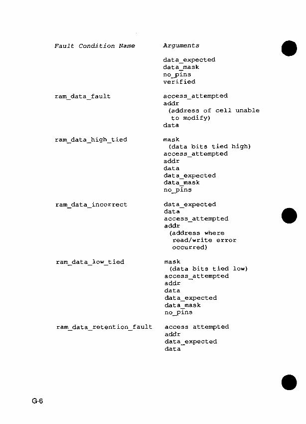
Fault Condition Name Arguments
dat a-expected da t a-ma s k nogins verified
ram - data-fault access-attempted addr (address of cell unable to modify)
data
ram-data-high-tied mask (data bits tied high)
access-attempted addr data data-expected data-mask nogins
ram-data-incorrect
ram-dat a-low-t ied
data-expected data access-attempted addr (address where read/write error occurred)
mask (data bits tied low)
access-attempted addr data dat a-expected dat a-mask nogins
ram-data-retention-fault access attempted addr data-expected data

ROM TEST FAULT CONDITIONS
Fault Condition Name Arguments
rom - addr-addr - tied addr upt 0 mask (addr bits tied together)
addrstep data-mask nogins
rom - data-data - tied
addr upto mask (addr. bits stuck)
addrstep data-mask nogins
addr upt 0 mask (data bits tied together)
addrstep da t a-ma s k nogins
addr upt 0 mask-low (data bits tied low)
mask-high (data bits tied high)
addrstep data - mask nogins
rom-data-high-tied-a11 addr upt 0 addrstep data-mask nogins

F a u l t C o n d i t i o n Name Arguments
rom-data-low-tied-all addr upt 0 addrstep data-mask nogins
rom-sig-incorrect s ig sig-expected addr upt 0
BUS TEST FAULT CONDITIONS
F a u l t Condi,t i on Name
bus-addr - high-tied
bus-addr-low-tied
bus-addr-tied
bus-data-high-tied
bus-data-low-tied
Arguments
mask (address bits tied high)
addr
mask (address bits tied low)
addr
mask (address bits tied together)
addr
mask (data bits tied high)
addr data
mask (data bits tied low)
addr data

Fault Condition Name Argumen t s
bus-data-t ied mask (data bits tied together)
addr data
MEMORY INTERFACE POD FAULT CONDITIONS
Fault Condition Name Arguments
messagel message2
m-bus-addr-high mask
m-bus-addr-low mask
mgod~buscycle~clock mask-stat mask-ctrl mask-misc
messagel message2
m g o d ~ s l o w ~ c l o c k mask
messagel message2
mask messagel message2
addr-expected mask high maskIlow
data-expected mask-high mask-low

GENERIC FAULT CONDITIONS
F a u l t C o n d i t i o n Name Argurnen t s
generic-fault message mask-stat mask-ctrl mas k-addr mas k-da t a mas k-mi s c
PRIMITIVE FAULT CONDITIONS
F a u l t C o n d i t i o n Name
clkmod-fuse-blown
iomod-dce
iomod-fuse-blown
iomod-current-fault
pod-addr-tied
pod-breakpoint
pod-ctl-tied
pod-data-incorrect
pod-data-tied
pod-forcing-active
pod-interrupt-active
Argurnen t s
iomod-nums
iomod-nums
mask (address bits tied together)
mask (control lines tied)
data data-expected
mask (data lines tied)
mask (forcing lines tied)
mask (interrupt line active)

Fault Condition Name Arguments
pod-misc-fault
pod-special
pod-timeout-bad-pwr
pod-timeout-enabled-line
pod-timeout-no-clk
pod-t imeout-recovered
pod-timeout-setup
pod-uutgower
podselftest-failed
probe-fuse-blown
110 FAULT CONDITIONS
Fault Condition Name
mask (miscellaneous signals faulted)
index
mask (enable line causing timeout)
code
Arguments
e r r-num err-msg

ARGUMENTS USED WITH BUILT-IN TESTS G.lO.
The following built-in tests raise the primitive fault conditions (listed in the previous section). In addition to the arguments required as indicated by each primitive fault condition, each built-in test adds the arguments listed in the following table:
B u i l t - i n T e s t Argumen t s
rampaddr
rampdat a
read
readblock
readstatus
rotate
toggleaddr
togglecont rol
toggledata
write
access-attempted addr
access-attempted addr data
access-attempted addr
access-attempted addr
(Does n o t r a i s e f a u l t c o n d i t i o n s )
access-attempted addr data
access-attempted addr
access-attempted ctl
access-attempted data addr
access-attempted data addr

Built -in Test
writeblock
writecontrol
write•’ ill
Arguments
access-attempted data addr access-attempted ctl
access-attempted data addr

Appendix H Generating 'Built-in
Fault Messages
OVERVIEW H.1.
This appendix relates the text of TL11 fault messages to the arguments used in the TLI1 fault command. With this information, you can produce the same fault messages as those produced by the TW1 default
0 Fault messages are one or two lines long, and each line can have up to three variatl'ons, depending on the absence or presence of particular arguments in the handler. For example, the podforcing - active fault condition can produce these different messages:
1. forcing signal <name> <pin> is active
2 . forcing signal <name> <pin> is active attempted to <action> at <address>
3 . forcing signal <name> <pin> is active attempted to <action> control <control>

Message 1 would be displayed if the following statement appeared in the program:
fault pod-forcing-active mask mask
Message 2 would be displayed if the following statement appeared in the program:
fault pod-forcing-active mask mask, access-attempted "read", addr $8000
Finally, message 3 would be displayed if the following statement appeared in the program:
fault pod-forcing-active mask mask, access-attempted "read", ctl $62
For the statements above, 62 is the argument value used for the argument named ctl, "read" is the argument value used for the argument named access-attempted, 8000 is the argument value used for the argument named addr, and mask is the variable name used to provide the argument value for the argument named mask.
Symbols H.l . I .
The following symbols and names are used in the tables that follow:
The argument is a smng. The argument is numeric. The argument is included in the handler. The message is always used for this fault condition. The first alternative for the fault message. The second alternative for the fault message. The third alternative for the fault message. The fourth alternative for the fault message. The fifth alternative for the fault message.

Message Variables H.1.2.
One of the following actions: write read
<name> A signal name.
<pin> A pin number or alphanumeric designation.
<data> A hexadecimal data value.
<pod-special message> A pod-dependent fault message.
A decimal number.
A UUT address.
<control> A control word.
Argument Names H.1.3.
mask, mas k-t ied, mas k-low, - A 64-character string of faulted mask-high (string) , bits, where 0 = not faulted, and mask-stat, mask-ctrl, 1 = faulted. mask-data, mask-addr, mask-misc
access-attempted (string) - UUT access when a fault condition occurred, (e.g. "read" or "write").
addr (numeric)
upto (numeric)
ctl (numeric)
- Address at which a fault condition occurred or the low address of an address range.
- High address in an address range.
- Value written to control lines of the UUT.

message, messagel, message2 (string)
verified (string)
addr-expected (numeric)
data-expected (numeric)
code (numeric)
index (numeric)
data (numeric)
sig (numeric)
sig-expected (numeric)
test-type (string)
iomod-nums (numeric)
data-mask (numeric)
addrstep (numeric)
no-pins (numeric)
- Message written to the display.
- Parameter indicating that a fault condition has been verified, where verified = " ~ o n f i e d ' ~ or "not confirmed. "
- Address expected during a test.
- Data expected during a test.
- Pod self-test error code.
- Index into a table of pod special error messages.
- Data read from or written to the UUT.
- Faulty signature read in a ROM test.
- Signature expected in a ROM test.
- The type of test being executed.
- A bit mask for the faulty VO module number (the least- significant bit is ID module 1).
Example: If iomod-nums is 3, it refers to both VO module 1 and VO module 2.
- Mask of valid data bits, where 0 = invalid bit, 1 = valid bit.
- Address increment.
- Pin numbers are not to appear in message text, where (0 = pins, 1 = no pins.)

err-num (numeric) err-msg (string)
- Arguments describing an error raised under special conditions as a fault (e.g. the io-error fault).
HOW TO READ THE FAULT-MESSAGE TABLES H.2.
In the tables that follow, the fault conditions are organized alpha- betically, the Type column shows whether the arguments for that fault condition are string or numeric variables. Columns 1 , 2 , 3, 4 or 5 contain an x if the related argument is needed to produce the fault message associated with that column.
For example, in the bus addr tied fault condition (next page), the arguments mask, accessattem~ted, and addr are needed in the fault condition handler if youwant MESSAGE 2 to be displayed. If you prefer MESSAGE 3, use the mask, access attempted, addr, and data arguments. To get MESSAGE 1, include The mask argument in your handler.

FAULT MESSAGE TABLES H.3.
Fault Condition and Arguments
Type Fault Message Alternutives
bus-addr-high-tied I I I I I mask I s I x I x I I access-attempted I s I 1 x 1 I addr I n I 1 x 1 I
MESSAGE 1: addr line <name> <pin> stuck high MESSAGE 2 : attempted to <action> at <address>
bus-addr-low-tied I I I I I I mask I s I x I x I I I access-attempted I s I 1 x 1 I I - addr I n I 1 x 1 I I
MESSAGE 1: addr line <name> <pin> stuck low MESSAGE 2: attempted to <action> at <address>
bus-addr-tied mask access-attempted addr data
I I I I I I I s I X I X I X I I I s I I X I X I I I n I I x l x l I I n I I 1 x 1 I
MESSAGE 1: addr line <name> <pin> tied MESSAGE 2: attempted to <action> at <address> MESSAGE 3: attempted to <action> data <data> at
<address>

a Fault Condition and Type Fault Message Arguments Alternatives
bus-data-high-tied I I I I I I mask I S 1 x 1 I I I
MESSAGE 1: data line <name> <pin> stuck high
bus-data-low-tied I I I I I I mask I S I x I x I I I
MESSAGE 1: data line <name> <pin> stuck low
bus data-tied mask
I I I I I I I S 1 x 1 I I I
MESSAGE 1: data line <name> <pin> tied
clkmod-fuse-blown I 1 * 1 I I I
MESSAGE 1: clock module fuse blown

Fault Condition and Arguments
Type Fault Message Alternatives
generic-fault message mask stat maskIctrl mas k-addr mask-dat a mas k-mi s c
I I I I I I I S 1 x 1 I I I I s 1 x 1 I I I I s 1 x 1 I I I I s 1 x 1 I I I I s 1 x 1 I I I I s 1 x 1 I I I
MESSAGE 1: <message> status line <name> <pin> control line <name> <pin> address line <name> <pin> data line <name> <pin> line <name> <pin>
io-error e r r-num err-msg
I I I I I I I n 1 x 1 I I I I s 1 x 1 I I I
MESSAGE 1: 1/0 error <err-num>: <err-msg>
iomod-current-f ault I I * I I I I
MESSAGE 1: 1/0 module overcurrent fault

Fault Condition and Type Fault Message Arguments Alternatives
iomod-dce iomod-nums access-attempted addr
I I I I I I I n 1 x 1 I I I I S 1 1 x 1 I I I n I 1 x 1 I I
MESSAGE 1: compare condition reached in 1/0 module <number>
MESSAGE 2: attempted to <action> at <address>
iomod-fuse-blown I I I I I I iomod-nums I n 1 x 1 I I I
MESSAGE 1: 1/0 module <number> fuse blown
m-bus-addr-high I I I I I I mask I s 1 x 1 I I I
MESSAGE 1: addr line <name> <pin> was high - expected low
m-bus-addr-low mask
MESSAGE 1: addr line <name> <pin> was low - expected high
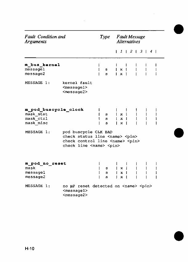
Fault Condition and Arguments
Type Fault Message Alternatives
m-bus-ke rnel messagel message2
MESSAGE 1: kernel fault <messagel> <message2>
m g o d ~ b u s c y c l e ~ c l o c k I I I I I I mask-stat I s 1 x 1 I I I mask-ctrl I s 1 x 1 I I I ma s k-mi s c I s 1 x 1 I I I
MESSAGE 1: pod buscycle CLK BAD check status line <name> <pin> check control line <name> <pin> check line <name> <pin>
mgod-no-reset mask messagel message2
MESSAGE 1: no pP reset detected on <name> <pin> <messagel> <message2>

Fault Condition and Arguments
Type Fault Message Alternatives
mgod-reset-addr addr-expected mask high mask~low
I I I I I I I n 1 x 1 I I I I s 1 x 1 I I I I S 1 x 1 I I I
MESSAGE 1: BAD reset address: <address> expected <name> <pin> was high <name> <pin> was low
m - pod-reset-data
a data-expected mask-high mask-low
I I I I I I I n 1 x 1 I I I I S 1 x 1 I I I I s 1 x 1 I I I
MESSAGE 1: BAD reset data: <data> expected <name> <pin> was high <name> <pin> was low
I I I I I I I s 1 x 1 I I I I S 1 x 1 I I I
MESSAGE 1: ROMl CS or OE is stuck invalid <messagel> <message2>

Fault Condition and Arguments
Type Fault Message Alternatives
m ~ p o d ~ s 1 o w ~ c l o c k mask
I I I I I I I S 1 x 1 I I I
MESSAGE 1: UTT clock <name> <pin> slow or stuck
I I I I I I I S 1 x 1 I I I I S 1 x 1 I I I
MESSAGE 1: microprocessor stopped or bad <messagel> <message2>
pod-addr-tied mask access-attempted addr data
MESSAGE 1: addr line <name> <pin> not drivable MESSAGE 2: attempted to <action> at <address> MESSAGE 3: attempted to <action> data <data> at
<address>
pod-breakpoint access-attempted addr
MESSAGE 1: breakpoint reached MESSAGE 2: attempted to <action> at <address>

Fault Condition and Arguments
Type Fault Message Alternatives
pod-ctl-tied mask access-attempted ctl addr data
I I I I I I I s I x l x l x l x l I s I I X I X I X I I n I I I 1 x 1 I n I I x l x l x l I n I I 1 x 1 I
MESSAGE 1: control line <name> <pin> not drivable MESSAGE 2: attempted to <action> at <address> MESSAGE 3: attempted to <action> data <data> at
<address> MESSAGE 4: attempted to <action> control <control>
a pod-data-incorrect I I I I I I data I n 1 x 1 I I I dat a-expected access-attempted addr
MESSAGE 1: read incorrect data <data> expected <data> MESSAGE 2: attempted to <action> at <address>
pod-data-tied mask access-attempted addr data
I I I I I I I S I X I X I X I I I s I I X I X I I I n I I x I x l I I n I I 1 x 1 I
MESSAGE 1: data line <name> <pin> not drivable MESSAGE 2 : attempted to <action> at <address> MESSAGE 3: attempted to <action> data <data> at

Fault Condition and Arguments
Type Fault Message Alternatives
pod-forcing-active I I I I I I mask I S I x I x I x I I access-attempted I s I I x I x I I ctl I n I I 1 x 1 I addr I n I 1 x 1 I I
MESSAGE 1: forcing signal <name> <pin> is active MESSAGE 2: attempted to <action> at <address> MESSAGE 3: attempted to <action> control <control>
pod-interrupt-active I I I I I I mask I s I x I x I x I I access-attempted I S I I x I x I I ctl I n I I 1 x 1 I addr I n I 1 x 1 I I
MESSAGE 1 : interrupt <name> <pin> is active MESSAGE 2: attempted to <action> at <address> MESSAGE 3: attempted to <action> control <control>
pod-miac-fault mask access-attempted ctl data addr
I I I I I I I s I x I x I x l x l x I S 1 I X I X I X I X I n I I I 1 x 1 I n I 1 x 1 I I I n I 1 x 1 I I x
MESSAGE 1: <name> fault <pin> MESSAGE 2 : attempted to <action> data <data> at
<address> MESSAGE 3: attempted to <action> MESSAGE 4: attempted to <action> control <control> MESSAGE 5 : attempted to <action> at <address>

Fault Condition and Arguments
Type Fault Message Alternatives
pod-special index access-attempted addr
MESSAGE 1: <pod-special message> MESSAGE 2 : attempted to <action> at <address>
pod-timeout-bad-pwr I I * I I I I
MESSAGE 1: pod timeout bad UUT power supply
pod-timeout-enabled-line I I I I I I mask I s 1 x 1 I I I
MESSAGE 1: enabled line <name> <pin> causes t imeout
pod-timeout-no-clk I 1 * 1 I I I
MESSAGE 1: pod timeout bad UUT clock

Fault Condition and Arguments
Type Fault Message Alternatives
pod-timeout-recovered I I * l I I I access-attempted I s I I x I x I x I ctl I n I I I 1 x 1 addr I n I I 1 x 1 I
MESSAGE 1: pod t imeout recovered MESSAGE 2: attempted to <action> MESSAGE 3: attempted to <action> at <address> MESSAGE 4: attempted to <action> <control>
pod-timeout-setup I I * I I I I
MESSAGE 1 : setup causes pod timeout
MESSAGE 1: bad UUT power supply
podselftest-failed I I I I I I code I n I x l I I I
MESSAGE 1: pod selftest code = <number>
probe-fuse-blown I l * I I I I
MESSAGE 1: probe fuse blown
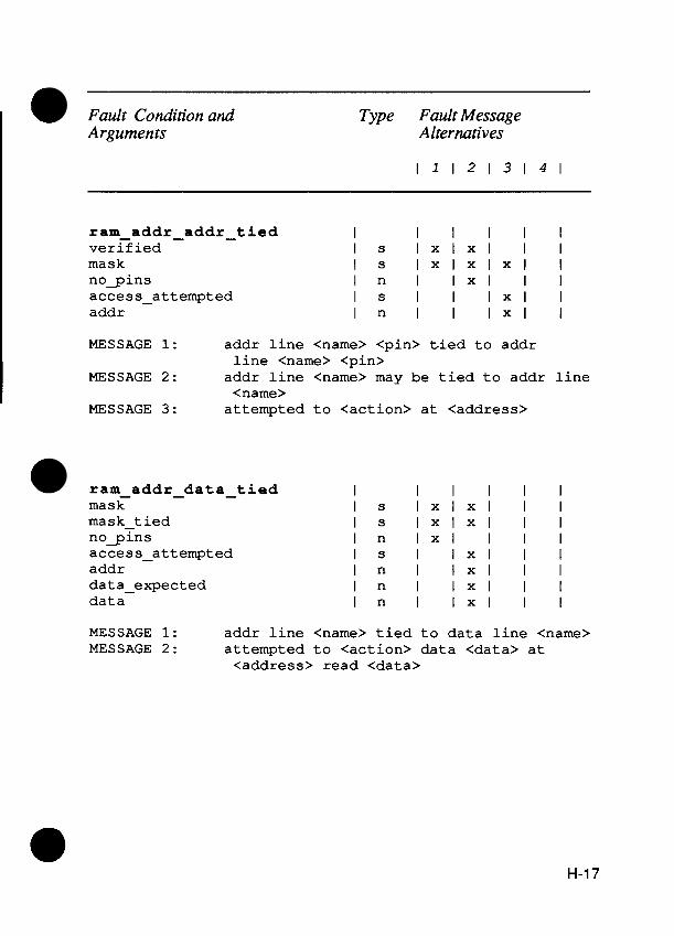
Fault Condition and Type Fault Message Arguments Alternatives
ram-addr-addr-t ied I I I I I I verified I S I x I x I I I mask I S I x I x l x l I nogins I n I 1 x 1 I I access-attempted I S I I 1 x 1 I addr I n I I 1 x 1 I
MESSAGE 1: addr line <name> <pin> tied to addr line <name> <pin>
MESSAGE 2 : addr line <name> may be tied to addr line <name>
MESSAGE 3 : attempted to <action> at <address>
ram-addr-data-t ied mask mask-t ied nogins access-attempted addr data-expected data
I I I I I I I S I X I X I I I I S I X I X I I I I n 1 x 1 I I I I S I 1 x 1 I I I n I 1 x 1 I I I n I 1 x 1 I I I n I 1 x 1 I I
MESSAGE 1: addr line <name> tied to data line <name> MESSAGE 2: attempted to <action> data <data> at
<address> read <data>

Fault Condition and Arguments
Type Fault Message Alternatives
ram-addr-data-tied-unconfirmed mask I s I x I x I I I mask-t ied I s I x I x I I I nogins I n 1 x 1 I I I access-attempted I S I 1 x 1 I I addr I n I 1 x 1 I I dat a-expected 1 n I 1 x 1 I I data I n I 1 x 1 I I
MESSAGE 1: addr line <name> may be tied to data line <name>
MESSAGE 2: attempted to <action> data <data> at <address> read <data>
ram-addr-fault mask nogins access-attempted addr
I I I I I I I S I X I X I I I I n 1 x 1 I I I I S I 1 x 1 I I I n I 1 x 1 I I
MESSAGE 1: addr line <name> stuck or open MESSAGE 2: attempted to <action> at <address>

Fault Condition and Type Fault Message Arguments Alternatives
ram-cell-cell-tied verified mask nogins access-attempted addr data-expected data
I I I I I I I s I 1 x 1 I I I S I X I X I X I I I n I x I x l I I I s I I 1 x 1 I I n I I 1 x 1 I I n I I 1 x 1 I I n I I 1 x 1 I
MESSAGE 1: memory cell for <name> coupled to memory cell for <name>
MESSAGE 2: memory cell for <name> may be coupled to memory cell for <name>
MESSAGE 3: attempted to <action> data <data> at <address> read <data>
ram cell-high-tied I I I I I I mask I s I X I X I I I nogins I n 1 x 1 I I I access-attempted I s I 1 x 1 I I addr I n I 1 x 1 I I data-expected I n I 1 x 1 I I data I n I 1 x 1 I I
MESSAGE 1: memory cell for <name> stuck high MESSAGE 2: attempted to <action> data <data> at
<address> read <data>

Fault Condition and Arguments
Type Fault Message Alternatives
ram-cell-low-tied I I I I I I mask I s I x I x I I I nogins I n 1 x 1 I I I access-attempted I s I 1 x 1 I I addr I n I 1 x 1 I I data-expected I n I 1 x 1 I I data I n I 1 x 1 I I
MESSAGE 1: memory cell for <name> stuck low MESSAGE 2: attempted to <action> data <data> at
<address> read <data>
ram-data-data-tied verified mask nogins access-attempted addr data-expected data
I I I I I I I s I I 1 x 1 I I s I X I X I X I X I I n I I x I x l I I s I I I 1 x 1 I n I I I 1 x 1 I n I I I 1 x 1 I n I I I 1 x 1
MESSAGE 1: data line <name> <pin> tied to data line <name> pod <pin>
MESSAGE 2: data line <name> tied to data line <name> MESSAGE 3: data line <name> may be tied to data line
<name> MESSAGE 4: attempted to <action> data <data> at
<address> read <data>

Fault Condition and Type Fault Message - - Arguments ~lternatives-
ram-data-f ault access-attempted addr data
MESSAGE 1: cannot modify RAM data MESSAGE 2: attempted to <action> at <address> read
<data>
ram-data-high-tied I I I I I I mask I s I x I x I x I I nogins access-attempted addr data-expected data
MESSAGE 1: data line <name> <pin> stuck high MESSAGE 2: data line <name> stuck high MESSAGE 3: attempted to <action> data <data> at
<address> read <data>
ram-data-incorrect I I I I I I data I n 1 x 1 I I I data-expected I n 1 x 1 I I I access-attempted I s I 1 x 1 I I addr I n I 1 x 1 I I
MESSAGE 1: read incorrect data <data> expected <data> MESSAGE 2: attempted to <action> at <address>

Fault Condition and Arguments
Type Fault Message Alternatives
ram-data-low-tied I I I I I I mask I s I x I x I x I 1 nogins I n I 1 x 1 I I access-attempted I s I I 1 x 1 I addr I n I I 1 x 1 I data-expected I n I I 1 x 1 I data I n I I 1 x 1 I
MESSAGE 1: data line <name> <pin> stuck low MESSAGE 2: data line <name> stuck low MESSAGE 3: attempted to <action> data <data> at
<address> read <data>
ram data-retention-fault I I I I I I access-attempted I s I 1 x 1 I I addr I n I 1 x 1 I I data-expected I n I 1 x 1 I I data I n I 1 x 1 I I
MESSAGE 1: RAM data retention fault (bad refresh?) MESSAGE 2: attempted to <action> data <data> at
<address> read <data>
ram-addr-addr-tied I I I I I I mask I s I x I x I I I nogins I n 1 x 1 I I I addr I n I 1 x 1 I I upt 0 I n I 1 x 1 I I
MESSAGE 1: addr line <name> tied to addr line <name> MESSAGE 2: testing from addr <address> to <address>
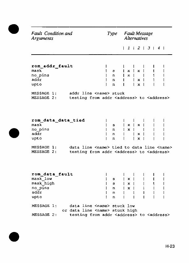
* Fault Condition and Type Fault Message Arguments Alternatives
rom-addr-fault mask nogins addr upt 0
I I I I I I I s I X I X I I I I n 1 x 1 I I I I n I 1 x 1 I I I n I 1 x 1 I I
MESSAGE 1 : addr line <name> stuck MESSAGE 2 : testing from addr <address> to <address>
ram-data-data-tied I I I I I I mask I s I x I x I I I nogins addr upt 0
MESSAGE 1 : data line <name> tied to data line <name> MESSAGE 2 : testing from addr <address> to <address>
rom-data-fault mask-low mask-high nogins addr upt 0
I I I I I I I S 1 x 1 I I I I s 1 x 1 I I I I n 1 x 1 I I I I n I I I I I I n I I I I I
MESSAGE 1: data line <name> stuck low or data line <name> stuck high
MESSAGE 2: testing from addr <address> to <address>

Fault Condition and Arguments
Type Fault Message Alternatives
rom-data-high-tied-a11 I I * I I I I addr I n I 1 x 1 I I upto I n I 1 x 1 I I
MESSAGE 1: all ROM data bits stuck high MESSAGE 2: testing from addr <address> to <address>
rom-data-low-tied-all I 1 * 1 I I I addr I n I 1 x 1 I I upto I n I 1 x 1 I I
MESSAGE 1: all ROM data bits stuck low MESSAGE 2 : testing from addr <address> to <address>
rom-sig-incorrect I I I I I I s ig I n 1 x 1 I I I sig-expected I n 1 x 1 I I I addr I n I 1 x 1 I I upto I n I 1 x 1 I I
MESSAGE 1: read incorrect sig <data> expected <data> MESSAGE 2: testing from addr <address> to <address>
unknown-fault access-attempted addr data
MESSAGE 1: unknown or intermittent fault occurred MESSAGE 2: attempted to <action> data <data> at
<address>

Appendix I Pod-Related Information
POD CALIBRATION AND OFFSETS 1.1.
Calibration is the process by which the internal delay lines in the UO module and probe are adjusted to correctly align (in time) the clock and signals to be sampled. To calibrate an UO module or probe to a pod for a particular pod sync mode, you are prompted to probe a signal on the UUT. The specified reference edge on that signal is found by adjusting the delay lines in the 110 module or probe relative to the internal PodSync signal, The appropriate delay, labeled "tcal" in Figure 1-1, may vary from one pod to another and from one sync mode to another. If calibration is not performed, then a default setting is used for the tcal value. When calibration is performed, the measured value for tcal replaces the default value.
Once the reference edge is found, then an offset is applied to that edge to determine just where in time the UO module or probe will latch data.
The following is an example for an imaginary "xyz" pod showing how the offset data is listed in this appendix and how this data would apply to real waveforms. Pod calibration and offset data for the "xyz" pod would appear in this appendix as follows:
Sync Mode UUT S i g n a l Edge o f S i g n a l O f f s e t f rom Edge
ADDR -ALE rising -24 ns

In the imaginary "xyz" pod, the reference edge for address sync is the rising edge of the -ALE (address latch enable) signal. Furthermore, the offset data shows that a valid address is best captured when sampled 24 nanoseconds before the rising edge of -ALE. (A positive offset would have indicated that the address should be latched after the reference edge.)
The waveforms corresponding to the above example are shown in Figure 1-1. The - symbol indicates that both the ALE signal and the PodSync signal are active low.
As a result of the calibration process, the offset value is set to the default value for the sync mode in use. If other offsets are required, the TL/1 setoffset command can be used. See the setoffset command and the getoffset command in the "TL11 Alphabetical Reference" section of this manual.
POD INFORMATION FOR 9100A/9105A USERS 1.2.
In addition to the pod information in Fluke pod manuals, the Supplemental Pod Information for 9100Al9105A Users Manual provides the following additional information for each pod:
Address space options: Shows the parameter names, para- meter values, and all legal combinations of parameter values. Address space options are accessed through the OPTIONS key at the operator's keypad and display or through the TLI1 getspace command.
Pod-specific set-up information: Shows the parameters that are available through the SETUP MENU key on the operator's keypad and display or through the TLI1 podsetup command. These parameters are used to set-up the pod for a specific UUT.

Data latched here
1 2 4 n T t a ,
Specified reference edge 4
Figure 1-1 : Calibration and Offset Example Waveforms

TLI1 support programs: Shows a list of the TL11 programs that are available in the pod library. These programs provide convenient interfacing with any special functions built into the pod. Pod sync calibration and offset data: Shows the UUT signal, active (reference) edge of the signal, and the default offset from the specified reference edge for each sync mode.
SUMMARY OF 80186 POD SUPPLEMENTAL INFORMATION 1.3.
The following information is included as one example of the information available in The Supplemental Pod Information for 9100A/9105A Users Manual. This information is particularly helpful for use with the getspace command, for pod-specific setup information when using pod- specific TL11 support programs, and for adjusting pod sync calibration.
Address Space Options:
Parameter Names : mode space size
Parameter Values : NORMAL
NORMAL NORMAL NORMAL DMA DMA DMA DMA
MEMORY MEMORY 1 /o I / O MEMORY MEMORY
1 /o I / O
Pod-Specific Setup Information:
WORD BYTE WORD BYTE WORD BYTE WORD BYTE
POD-CTL - P o d c o n t r o l addresses STDBY-AD - S t a n d b y read address RESET - R e s e t

SEG - REG - Segment r e g i s t e r s EXTRA - Ext ra segment r e g i s t e r STACK - Stack segment r e g i s t e r CODE - Code segment r e g i s t e r DATA - Data segment r e g i s t e r
ERR - MASK - E r r o r masks SUMMARY - E r r o r summary mask CTRL-DR - Cont ro l d r i v a b i l i t y e r r o r mask ACT FRC - Forc ing s i g n a l e r r o r mask ACTIINT - Act ive i n t e r r u p t s i g n a l mask SEG DR - Segment d r i v a b i l i t y e r r o r mask A D D ~ D R - Address d r i v a b i l i t y e r r o r mask DATA-DR - Data d r i v a b i l i t y e r r o r mask INTA-TO - I n t e r r u p t acknowledge and t i m e r ou t
e r r o r mask CHIP - SEL - Chip select e r r o r mask
CS-REG - Chip select r e g i s t e r s MPCS - MPCS r e g i s t e r MMCS - MMCS r e g i s t e r PACS - PACS r e g i s t e r LMCS - LMCS r e g i s t e r UMCS - UMCS r e g i s t e r
DMA-CHO - DMA channel 0 CTRL-WD - Cont ro l word TRNS-CNT - Trans fe r count DP UPPR - D e s t i n a t i o n p o i n t e r (upper f o u r b i t s ) DPILWR - D e s t i n a t i o n p o i n t e r ( lower s i x t e e n b i t s ) SP UPPR - Source p o i n t e r (upper f o u r b i t s ) SPILWR - Source p o i n t e r ( lower s i x t e e n b i t s )
DMA - C H 1 - DMA channel 1 CTRL-WD - Cont ro l word TRNS-CNT - Trans fe r count DP UPPR - D e s t i n a t i o n p o i n t e r (upper f o u r b i t s ) DPILWR - D e s t i n a t i o n p o i n t e r ( lower s i x t e e n b i t s ) SP-UPPR - Source p o i n t e r (upper f o u r b i t s ) SP-LWR - Source p o i n t e r (lower s i x t e e n b i t s )
TIMER0 - T i m e r 0 M/C-WD - Mode/Control word r e g i s t e r MAX-CNTA - Max count A r e g i s t e r MAX CNTB - Max count B r e g i s t e r COUNT - Count r e g i s t e r

TIMER1 - T i m e r 1 M/C-WD - Mode/Control word r e g i s t e r MAX-CNTA - Max coun t A r e g i s t e r MAX CNTB - Max coun t B r e g i s t e r COUNT - Count r e g i s t e r
TIMER2 - T i m e r 2 M/C-WD - Mode/Control word r e g i s t e r MAX CNTA - Max coun t A r e g i s t e r COUNT - Count r e g i s t e r
INT-CNTR - I n t e r r u p t c o n t r o l l e r r e g i s t e r s INT3 - INT3 c o n t r o l r e g i s t e r INT2 - INT2 c o n t r o l r e g i s t e r I N T l - I N T l c o n t r o l r e g i s t e r INTO - I N T O c o n t r o l r e g i s t e r DMAl - DMAl c o n t r o l r e g i s t e r DMAO - DMAO c o n t r o l r e g i s t e r TMR CTL - TIMER c o n t r o l r e g i s t e r INTISTAT - I n t e r r u p t c o n t r o l s t a t u s r e g i s t e r INT REQ - I n t e r r u p t r e q u e s t r e g i s t e r IN-SERV - ~ n - s e r v i c e r e g i s t e r PRI-MSK - P r i o r i t y mask r e g i s t e r MASK - Mask r e g i s t e r EOI - EOI r e g i s t e r INT-VECT - I n t e r r u p t v e c t o r r e g i s t e r
TLII Support Programs:
QWK RD Quick l o o p i n g r e a d Q W K ~ R Quick l o o p i n g w r i t e QWK-ROM Quick ROM test QWK RAM Q u i c k RAM test Q W K ~ R A M P Quick ramp QWK-FILL Quick f i l l
Pod Sync Cali bration
Sync Mode UUT S i g n a l
ADDR ALE DATA -DEN I N T A -DEN
Edge o f S i g n a l O f f s e t from Edge
f a l l i n g r i s i n g r i s i n g

Appendix J 91 OOA/gl O5A Error
Numbers
INTRODUCTION J.1.
The 9100Al9105A associates an error number with each possible error that the instrument can encounter during operation. This association is system-wide. A given error has the same error number in all facets of system operation.
Also associated with each error is an error message, which is a string describing the error. For some errors, this error message string is modified to reflect certain error parameters (for example, if a file cannot be opened because it does not exist, the error message will include the name of the file).
Normally, error numbers are invisible to the operator or programmer, with only the error message displayed when an error is encountered. However, some errors can be dealt with in a TL11 program, where it is more convenient to check error numbers than message strings when particular errors are handled differently .
ERROR NUMBERS J.2.
Figure J-1 contains only those errors that are relevant to TW1 programming. The number of errors which can be generated by the 9100Al9105A is much larger than this list; however, errors not in this table cannot be intercepted by TL11

programs. Also, error numbers from 900 through 999 are reserved for user-defined errors, which are sometimes needed in programs which deal with both system-specific and application- specific errors.
Error messages which are modified to reflect the actual error parameter(s) are shown with the error parameter(s) in italics.
The error numbers that appear in the following table are the 'err_numl argument to the io-error fault. This fault is raised by various VO statements, including print and input.
Error Number Error
Path Table full
Bad Path Number
Bad Mode
Out of Memory
End of File
File Not Accessible
Bad Path Name
Path Name Not Found
Creating Existing File
Phone hangup occurred (modem)
Out of Memory
Directory not empty
I10 error - bad disk sector number
Disk is Write Protected
Figure J-1 : List of Error Numbers

Error Number Error
10 error -- bad CRC verify
qead Error
Nrite Error
Uo disk in drive
Unreadable or unformatted disk
Disk Full
Incompatible Disk Type
I10 Device Busy
Disk ID error
File record is busy (locked out)
Non-sharable file busy
Device is format protected; cannot format
IEEE-488 output buffer not empty
Operation requires an IEEE-488 address list
Operation requires system controller capability
Operation requires controller-in-charge capability
Figure J-1 : List of Error Numbers (cont.)

Error
IEEE-488 interface hardware is busy
Not configured for parallel poll
IEEE-488 transaction timed out
Operation requires controller capability
No listeners on the IEEE-488 bus
Cannot go to local in local lockout
I10 attempted before any channels opened.
lnvalid BAUD Setting
lnvalid Parity Setting
lnvalid Number of Parity Bits
lnvalid Number of Stop Bits
file is write protected
file does not exist
Text files cannot be opened in update mode
There is no Video Interface
There is no Operator Display
Ports and files cannot have windows
Figure J-1 : List of Error Numbers (cont.)

Appendix K 91 00- Series
Software Error Report Form

9100 SERIES SOFTWARE ERROR REPORT FORM
We would like to thank you for taking the time to let us know about any bugs you encounter while using the 9100A or the 9105A. This information will help us in our goal of providing the best possible products for our customers.
We suggest that you retain this form as an original and use a photocopy for reporting a bug.
Name Date
Company
Department Mail Stop
Address
Country
Phone ( )
Model: 9100A 9105A
Serial Number:
Software Version:
Pod In Use:
Description of Problem:
(Continued on next page)

What sequence of steps led to the problem? a
What was displayed on the operator's display when the problem was encountered?
Line 1:
Line 2:
Line 3: a Was the problem intermittent? Yes No
Were you able to work around the problem? If so, how?
Please return the completed form to:
John Fluke Mfg. Co., Inc. MRBD Sales Support M/S 251 E Box C9090 Everett. WA 98206

Index
NOTE
TLIl commands are not - listed in this index. They are located alphabetically in Section 3.
0 Address Space Options, 1-4 ~nnunciator control, 8-3 Argument names, G-2, H-3 Arguments used with built-in tests, G-12 Arithmetic Operators, 2-1 2 Arrays, 2-1 1 ASCII Codes, A-1
Beeper control, 8-4 Bit mask operators, 2-1 5 Bit shifting operators, 2-1 5 Block statements, 2-22 Bus test faults, G-8
Calibration, 1-1 Case sensitive, 2-2,2-3 Case, 2-2 Comment, 2-22 Conditional expressions, 2-1 7 Control codes, B-1 Cursor control seauences. 8-2

Data types, 2-8 Device list, 2-6 Device names, 2-4 Display attributes, B-2 Display characters for the monitor, B-5 Display mode sequences, B-2 Double-quote character, 2-10
Editing control, B-3 Erasing, B-1 Error Numbers
91 OOA/9l OSA, J-1 Error table, J-1 Esc key, B-1
Fault condition arguments, G-2, H-6 handling, G-1 messages, H-6 raising, H-1
Fault message tables, H-6 File and directory names, 2-2, 2-3 Floating-point, 2-9 Functions, 2-20
I/O module and probe, 2-20 pod, 2-20 special, 2-20
Generating built-in fault messages, H-1 Generic faults, G-10
Handling built-in fault conditions, G-1 How to read fault message tables, H-5
I10 module cliplpin mapping, E-1
Keypad mapping to TU1 output, C-1
Logical operators, 2-1 3
Memory interface pod faults, G-9 Message variables, H-3 Monitor display, B-1
Name conventions, 2-2 Non-printing characters, 2-10 Numeric type, 2-8

Numeric type, 2-8 Numeric values, 2-8
Operator's keypad mapping, C-1 Operators, 2-1 1 Order of evaluation, 2-1 6 Organization of manual, 1-2 Other built-in test faults, G-12
Parentheses, 2-1 7 Pin names, 2-7 Pin numbers, 2-7 Pod calibration and offsets, 1-1 Pod related information, 1-2 Pod supplemental information, 1-4 Pod sync calibration data, 1-6 Pod-specific set-up information, 1-2 Pod-specific setup information, 1-4 Primitive fault conditions, G-10 Programmer's keyboard mapping to TU1 input, D-1
Ram test faults, G-4 Ref pins, 2-7 Reference designator names, 2-7 Relational Ooerators. 2-12 ROM test faults, G-7
Simple statements, 2-22 Single quote character, 2-2 Software error report form, J-6 Special display characters, B-4 String
operators, 2-1 4 Symbols, H-2
used in displaying IC's, B-5
Tab stops, B-3 TLI1
language conventions, 2-1 reserved words, F-1 statement conventions, 2-22 support programs, 1-6
Type conversion operators, 2-21