tube bender control manual rev3a - machmotion.com home types/tube bender/t… · congratulations on...
TRANSCRIPT

MACH MOTION / TUBE PROCESS
Tube Bender Control X15-250-300 User’s Manual
5/31/2011
MachMotion.com Tube Process LLC http://www.machmotion.com www.tubeprocess.com 14518 County Road 7240, Newburg, MO 65550 2302 Pod Drive, Vista, CA 92084 (573) 368-7399 • Fax (573) 341-2672 760-415-6945 – Fax 509-695-7962 Copyright © 2010, MachMotion.com All rights reserved.
Things you need to know about how to operate a MachMotion Tube Bender Control.

2
Contents
Contents .......................................................................................................................................... 2
Your Tube Bender Control....................................................................................................... 5
Getting Started ............................................................................................................................... 6
Manual Mode ............................................................................................................................... 9
The Carriage ................................................................................................................................. 10
Limit Switches .............................................................................................................................. 11
The Rotary Axis............................................................................................................................ 12
The Bending Arm ......................................................................................................................... 13 Return the C Arm ............................................................................................................................................. 15
Bender Functions ........................................................................................................................ 15 Pipe Clamp ........................................................................................................................................................ 16 Collet .................................................................................................................................................................. 16 Follower ............................................................................................................................................................. 16 Pressure Die ..................................................................................................................................................... 17 Mandrel .............................................................................................................................................................. 17
Settings ......................................................................................................................................... 18
Bending Sequence................................................................................................................... 20 Part Configuration ............................................................................................................................................ 21
The part configuration screen is where all the settings for the part program are entered. This will
be saved in the code so that when you load your file months later all the settings will be loaded
with it. ............................................................................................................................................................. 21 Pipe Dimensions .......................................................................................................................................... 21 Enable Options ............................................................................................................................................. 21
Create a Bend ............................................................................................................................... 22 Y Axis Point To Point ................................................................................................................................... 23 Y Clearance Feed ........................................................................................................................................ 25 Part Specifics ................................................................................................................................................ 25 Load Position ................................................................................................................................................ 26 Die Radius .................................................................................................................................................... 26 Pressure Die Interference Zone ................................................................................................................ 26
Springback Compensation ......................................................................................................... 27 Create Bending Sequence .............................................................................................................................. 29
Normal Mode ................................................................................................................................................ 30 Advanced Mode ........................................................................................................................................... 31 Test Bend ...................................................................................................................................................... 32 Capture Move ............................................................................................................................................... 33 Save Bend .................................................................................................................................................... 34

3
Carriage Safety Check ................................................................................................................................ 34 Last Bend ...................................................................................................................................................... 35
Delete a Bend ............................................................................................................................... 37 Delete Last Bend .............................................................................................................................................. 37 Delete All Bends ............................................................................................................................................... 37
Disable a Bend ............................................................................................................................. 38
Change a Program ....................................................................................................................... 38 Change Previous Bend ................................................................................................................................... 39
Run Mode ................................................................................................................................... 41
Open a Program ........................................................................................................................... 42 Old Program ...................................................................................................................................................... 42 Recent Program ............................................................................................................................................... 43
Run a Program ............................................................................................................................. 43 Start a Program ................................................................................................................................................ 44 Pause a Program ............................................................................................................................................. 45 Stop a Program ................................................................................................................................................ 45 Restart a Program ............................................................................................................................................ 45 Step through a Program .................................................................................................................................. 46 Program Display ............................................................................................................................................... 46 Run One Bend at a Time ................................................................................................................................ 47 Emergency Stop ............................................................................................................................................... 47
Close a Program .......................................................................................................................... 47
Run Functions .............................................................................................................................. 48
Shutting Down the Control .................................................................................................... 49
Unit Conversion ........................................................................................................................... 50

4
This page was intentionally left blank.

5
Your Tube Bender Control
Congratulations on purchasing your MachMotion Tube Bender Control. This software was
designed to be very simple and easy to learn, while not compromising on functionality. It offers
you complete control of each of the functions of the machine in addition to many complicated
automatic procedures. In this manual you will find everything you need to know to operate your
tube bender.
Note: This is a user’s manual, not a teacher’s manual! This manual
assumes you know the basics of tube benders and their functions.
****************************************************************************
Emergency Stop
In case of an emergency, press the large red E-Stop button located on the
operator’s panel (Figure 3 on page 8), rear electrical cabinet and the side of the
machine. All motion will stop immediately.
NOTE: FEED HOLD OR CYCLE STOP WILL COMPLETE THE CURRENT
MACHINE ACTION BEFORE STOPPING.
****************************************************************************
6
Getting Started
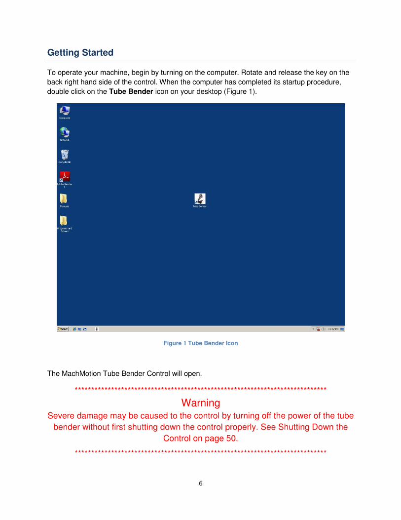
To operate your machine, begin by turning on the computer. Rotate and release the key on the
back right hand side of the control. When the computer has completed its startup procedure,
double click on the Tube Bender icon on your desktop (Figure 1).
Figure 1 Tube Bender Icon
The MachMotion Tube Bender Control will open.
****************************************************************************
Warning
Severe damage may be caused to the control by turning off the power of the tube
bender without first shutting down the control properly. See Shutting Down the
Control on page 50.
****************************************************************************

7
Figure 2 Mach Motion Tube Bender Control
This control has three modes: Run Mode, Manual Mode, and Bending Sequence. Before you
can proceed to any of the modes, the tube bender must be homed. To home, pull out the E-
Stop button on the operator’s panel. See Figure 3 below. Then push the Power On button to
start the hydraulic pump and supply power to the servo drives.
8
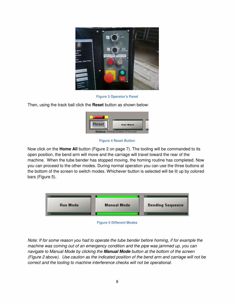
Figure 3 Operator's Panel
Then, using the track ball click the Reset button as shown below:
Figure 4 Reset Button
Now click on the Home All button (Figure 2 on page 7). The tooling will be commanded to its
open position, the bend arm will move and the carriage will travel toward the rear of the
machine. When the tube bender has stopped moving, the homing routine has completed. Now
you can proceed to the other modes. During normal operation you can use the three buttons at
the bottom of the screen to switch modes. Whichever button is selected will be lit up by colored
bars (Figure 5).
Figure 5 Different Modes
Note: If for some reason you had to operate the tube bender before homing, if for example the
machine was coming out of an emergency condition and the pipe was jammed up, you can
navigate to Manual Mode by clicking the Manual Mode button at the bottom of the screen
(Figure 2 above). Use caution as the indicated position of the bend arm and carriage will not be
correct and the tooling to machine interference checks will not be operational.

9
Manual Mode
In Manual Mode you have control of each moving part of your tube bender. Each function, such
as the pipe clamp and pressure die, can be operated in this mode. You can also do manual
bends. This is a good place to start when learning the control.
In this section you are going to begin by learning how to operate the Y, B, and C axes. Then you
will also discover how to operate each of the other functions of the tube bender independently.
Finally you learn what semi-auto mode is and how to use it. To begin, click on the Manual
Mode button (Figure 2 on page 7). You will see the following screen:
Figure 6 Manual Mode

10
The Carriage
The carriage, or Y axis, can be moved forward or backwards. All moves are incremental,
meaning that the carriage moves however far you command it to move from the current
position. The first input field on the left of the screen labeled “Y” is the + or - distance for the
carriage to move along the linear rail (Y) (Figure 7).
Figure 7 Input Fields
The distance value is in inches or millimeters depending on how your machine is configured
(See Unit on page 50). To move the carriage, enter your distance into the input field, adjust the
Feed rate Override vertical slider to set the speed between 0 and 100% and click the Run
button next to it. The carriage will move the distance that you commanded it.
If you command it to move farther than the machine limits will allow, an error will pop up (Figure
8).
Figure 8 Invalid Move
To manually jog the carriage, or Y axis, click on the Jog Y button to the right of the Feed rate
slider. Then, while holding the enable button (green pushbutton switch to the left side of the
control console), press + or – push buttons (black pushbuttons on the operator’s panel). The Y
axis will move as long as you hold the buttons. Adjust the Jog Rate slider to control the speed.

11
******************************************************************************
DANGER:
You can crash the carriage if you are not careful! If you hit a limit switch at high
speeds the carriage will continue to coast and may collide with the end of travel
stop or the tooling at the front of the machine.
******************************************************************************
On the right side of the Manual Mode screen there are Digital Read Outs (or DRO’s) labeled Y,
B and C. They indicate the current position of the carriage and bend arm. The small DRO below
shows the absolute machine coordinates. This is the real position of each axis measured from
the homing switch. The large DRO indicates the commanded distance remaining while the axis
is moving.
Figure 9 Y, B and C Axis DRO
Limit Switches
If the Y axis over travel limit switch is hit, the control disables all motion. An error will be
displayed in the status bar at the very bottom of the screen. See Figure 10 below.

12
Figure 10 Limit Switch
To reset from a limit switch condition, follow the procedure outlined below.
1. Move the carriage off the limit switch and beyond the home proximity switch manually.
2. Press Reset (Figure 4).
3. Home the machine by clicking the Home All button (Figure 6 on page 9).
You should now be ready to continue operating your machine.
The Rotary Axis
The rotary axis, or B axis, can do positive or negative rotations. All movements are incremental.
The second input field on the left of the screen labeled “B” is the distance for it to move in
degrees. Viewing the B axis from the front of the tube bender, positive is counter-clockwise and
negative is clockwise.
Figure 11 B Input Field
To move the rotary axis, enter your distance into the input field and click the Run button next to
the input field. The B axis will rotate however many degrees you commanded it to. The B axis
can rotate at different speeds. To change the speed, adjust the Feed rate Override vertical
slider to set the speed between 0 and 100%
Note: Changing the Feed rate slider also changes the Y and C axes speed.

13
To manually jog the B Axis, click on the Jog B button to the right of the Feed rate slider. Then,
while holding the enable button (green pushbutton switch to the left side of the control console),
press + or – push buttons (black pushbuttons on the operator’s panel). The B axis will rotate as
long as you hold the buttons. Adjust the Jog Rate slider to control the speed.
The second large DRO on the right of the screen labeled B is the current position of the B axis
(Figure 12). The absolute machine coordinates are in the small DRO below it. This is the
distance from the home position.
Figure 12 B Axis DRO
The Bending Arm
The bending arm, or C axis, can only bend positive angles. All bends are in absolute
coordinates, meaning that they are referenced from the home position. The third input field on
the left of the screen is for the C axis. Again the value is in degrees.
Figure 13 C Input Field

14
****************************************************************************
DANGER:
Stand clear of the C arm or serious injury may be incurred. During each C bend
the pipe clamp, pressure die, mandrel and mandrel lubricator can all function.
Keep your hands and all other objects far away.
****************************************************************************
Make a Bend
To move the C axis, enter your angle into the input field and click the Run button next to the
input field. The clamp and pressure dies will close, then the C axis will bend to whatever angle
was commanded.
If the carriage is in the pressure die interference zone (i.e. the pressure die will collide with the
carriage if the die closes). The clamp will close, the collet will open and the carriage will back
out of the interference zone. The pressure die will then close and the C axis will move to the
commanded position.
While the C axis is bending, the Y axis changes to torque mode. In torque mode a set amount of
force is applied to the carriage. Immediately after a bend, the carriage switches back to the
normal mode.
The C axis can also move at different speeds. To change the speed, adjust the Feed rate
Override vertical slider to set the speed between 0 and 100%
Note: Changing the Feed rate slider also changes the Y and B axes speed.
To manually jog the bend arm, click on the Jog C button to the right of the Feed rate slider.
Then, while holding the enable button (green pushbutton switch to the left side of the control
console), press + or – push buttons (black pushbuttons on the operator’s panel). The C axis will
move as long as you hold the buttons. Adjust the Jog Rate slider to control the speed.
The third large DRO on the right displays the current position of the C arm.
15
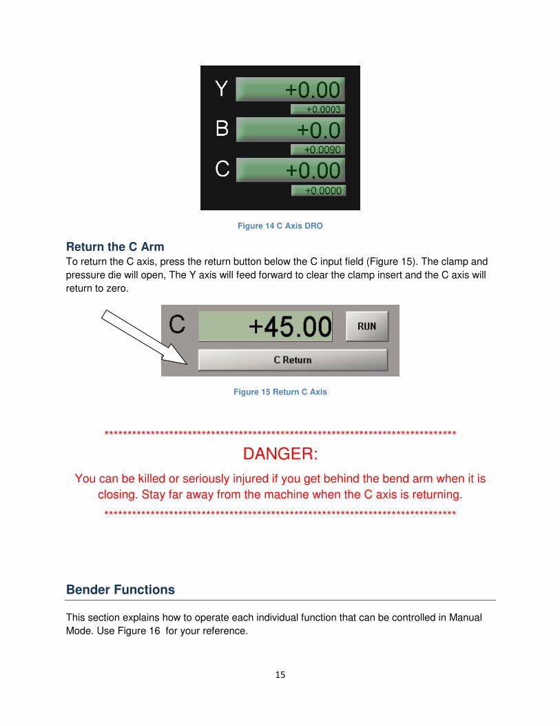
Figure 14 C Axis DRO
Return the C Arm To return the C axis, press the return button below the C input field (Figure 15). The clamp and
pressure die will open, The Y axis will feed forward to clear the clamp insert and the C axis will
return to zero.
Figure 15 Return C Axis
****************************************************************************
DANGER:
You can be killed or seriously injured if you get behind the bend arm when it is
closing. Stay far away from the machine when the C axis is returning.
****************************************************************************
Bender Functions
This section explains how to operate each individual function that can be controlled in Manual
Mode. Use Figure 16 for your reference.

16
Figure 16 Bender Functions
Note that each function box has vertical bars that light up when the box is selected. When the
function is selected you may move it incrementally by holding the Enable (green) button on the
left side of the console and selecting the direction with the + or – (black) buttons on the
console. The function will be commanded to move as long as you hold both buttons. The
motions are activated at a low system pressure for safety and to avoid damage to the tooling.
When you release the buttons all pressure is removed
To the right there is another smaller box labeled “Toggle”. When you are certain that the tooling
is properly installed and aligned, or is adjusted so that there is no danger of tooling damage, the
Toggle button can be selected to move the selected function at full system pressure. When the
function has completed its full range of motion, it will be held at full pressure in that position.
Clicking on the toggle button again will reverse the direction of the selected function
Note that the switch status for each function is shown by an illuminated box just below the
function button. The switches are used by the control to monitor the position of tooling during
machine operation. If the box is lit the switch is active. Other inputs and outputs connected to
the control can be monitored by the status of the input and output boxes to the right of the
function buttons.
Pipe Clamp To manually operate the pipe clamp, click the Pipe Clamp button (Figure 16). Holding the
enable button and pressing + will move the clamp toward the bend die to grip the tube. Holding
enable and pressing – will move the clamp away from the bend die to its open position. If the
toggle button is selected the clamp will change position. For instance, if the pipe clamp is
closed, clicking the button will open it up. Clicking it again will close the clamp.
Collet To manually operate the collet, click the Collet button (Figure 16). Each click of the button
clamps the collet or releases it. Jog and toggle mode operate the same for the collet.
Follower To manually operate the follower (pressure die forward and backward), click the Follower button
(Figure 16). Holding the enable button and pressing + will move the pressure die forward.

17
Holding enable and pressing – will move the pressure die back. If the toggle button is selected
the follower will move full stroke. For instance, if the follower is retracted, clicking the button will
move it forward the full length of the cylinder stroke. Clicking it again will retract the cylinder.
Pressure Die To manually operate the pressure die, click the Pressure Die button (Figure 16). Holding the
enable button and pressing + will move the Pressure die toward the bend die to grip the tube.
Holding enable and pressing – will move the pressure die away from the bend die to its open
position. If the toggle button is selected the pressure die will change position. For instance, if
the pressure die is closed, clicking the button will open it up. Clicking it again will close the
pressure die.
Mandrel To manually operate the mandrel, click the mandrel button (Figure 16). Holding the enable
button and pressing + will move the mandrel toward the bend die. Holding enable and pressing
– will move the mandrel back, away from the bend die. If the toggle button is selected the
mandrel will change position. For instance, if the mandrel is forward, clicking the button will
retract it. Clicking it again will advance the mandrel.
Mandrel Lube
To manually activate the mandrel lubrication pump, click the Mandrel Lube button (Figure 16).
Each click of the button operates the mandrel lube pump. Jog and toggle mode operate the
same for the mandrel lube function.
****************************************************************************
DANGER:
If you are doing a C bend, any of the above functions may operate if they are
enabled.
***************************************************************************

18
Settings
Clicking on the Settings button will open the following screen which allows setting the
parameters for several machine constants as well as selecting options for various equipment
included on your particular machine.
Figure 17 Settings
Soft limits This button is used to bring up a screen that allows changing the forward limit of
travel for the y axis. This value will change automatically depending on the dimensions of the
tooling installed on the machine.
MM – Inch These selection boxes are used to indicate the units of length for the Y axis. You
must use the procedure on page 51 to change units.
Time fields The three fields immediately below allow changing the time allotted for the pressure
die, clamp and mandrel to move to their commanded positions.

19
Max C Bend This is a field that sets the upper limit of the bend arm travel.
Table length is the distance from the tangent point on the bend die to the front of the collet
when the carriage is at its rear limit of travel (at the Y home limit switch).
Mandrel lubricator angle is the increment of bend arm motion when the mandrel lube pump is
activated. ie. A value of 5 means that the lube pump will be activated once every 5 degrees of
bend arm motion during the bend cycle. If it is enabled, the mandrel lubricator will turn on every
X number of degrees (X being whatever number is in the input field). It will stay on for X/2
degrees and then will be off for X/2 degrees.
Pressure Die Assist Delay is the time delay after the start of the bend when the pressure die
assist is activated.
Torque is the command sent to the Y axis during bending to allow the carriage to follow the
tube as it is being drawn into the arc of the bend.
Collet Depth is the distance the end of the tube is inserted into the collet.
C Homing Speed is the command sent to the bend arm to move it slowly to its home position
when the home all command is issued.
Options buttons on the right side of the screen allow selection of the functions present on your
particular machine.
Table Shift is for machines that move the carriage to the side to provide clearance for
feeding and rotation.
Pipe Clamp is for machines with a separate clamp valve for activating the clamp
mechanism
Collet clamp is for machines that have a powered collet closing mechanism.
Wiper is for machines with a retractable wiper die mechanism.
Pressure die is for machines with a separate powered pressure die closing mechanism.
Single Collet Output selects the type of control valve used to close the collet. When
active this button selects a single signal for collet control. i.e. if the signal is on the collet
is closed. If the signal is off the collet opens. When not active the control assumes the
collet open signal is separate from the collet close signal
Pressure Die Assist enables the powered follower. When disabled a spring or gravity
return of the follower is assumed.
Reverse Torque changes the direction of the Y axis command during the bending
action.

20
The small buttons at the lower left of the screen are for troubleshooting. The history button
opens a window that lists the sequence of steps the control has issued. The clear button erases
the history file.
Bending Sequence
The Bending Sequence is where you will create or edit your programs. This is designed to be
very user friendly and easy to understand. You can even bend pipe as you create your program
to make sure that everything will work correctly. To begin, click on the Bending Sequence
button.
Figure 18 Bending Sequence

21
Part Configuration
The part configuration screen is where all the settings for the part program are entered. This will
be saved in the code so that when you load your file months later all the settings will be loaded
with it.
Pipe Dimensions
Under Pipe Dimensions you can enter the diameter, length, and thickness of your pipe (Figure
19). Only the pipe length is used in calculations in the machine. The other values are for your
reference.
Figure 19 Pipe Dimensions
If you don’t know the developed length required for the part, you may leave this value to be
calculated after the part dimensions have been entered. At that time the Update button can be
selected to enter the calculated tube length.
Enable Options
The enable options have the following buttons:
• Mandrel
• Mandrel Lube
Click the buttons to turn off and on the LEDs. If a LED is on, that corresponding function will be
enabled for that program.
22
Create a new part file
To create a new part file, do the following:
1. Close the current program. Under Run Mode, close the program (See Close a Program
on page 47).
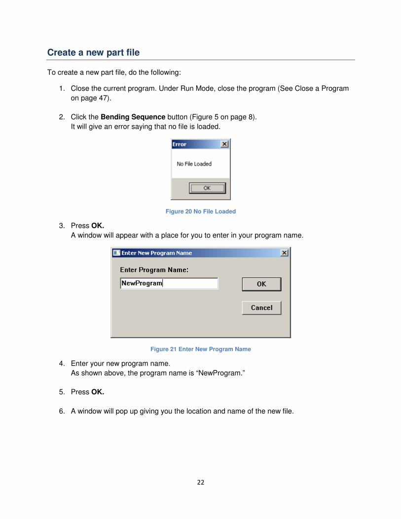
2. Click the Bending Sequence button (Figure 5 on page 8).
It will give an error saying that no file is loaded.
Figure 20 No File Loaded
3. Press OK.
A window will appear with a place for you to enter in your program name.
Figure 21 Enter New Program Name
4. Enter your new program name.
As shown above, the program name is “NewProgram.”
5. Press OK.
6. A window will pop up giving you the location and name of the new file.

23
Figure 22 New File Created
If another program with the same name exists, it will ask you if you want to overwrite the
existing file.
Figure 23 Erase Existing File
If you press Yes it will pop up with a new window showing where the new file was
created (Figure 22 on page 23). If you press No or Cancel start at step two again and
enter a different name.
7. Press OK.
The part configuration screen will be loaded (Figure 18 on page 20).
Y Axis Point To Point
To turn on Y Axis Point to Point data entry, click on the button and the LED will toggle.
Figure 24 Y Axis Point to Point
Y axis Point to Point turns on vector intersection mode. In this mode, you enter in the distance
from the vector to vector intersection point that defines each bend. See the diagram below. The
length of each red arrow is the distance you would use for Y Axis Point to Point data entry. The

24
tube bender control calculates, based on the die radius, how far to move the Y axis forward so
that the distance between bends will be correct.
Figure 25 YBC Bending
Note: You can only bend less than 180 degrees in Y Axis Point to Point mode. When you save
the bend it will give a divide by zero error if you try to bend more than 180 degrees.
If you do not use YBC bending, you have to enter in the distance between the tangent points of
each bend. The distance of the red arrows in the diagram below would be used if YBC was
disabled.

25
Figure 26 Distance Between Bends
Y Clearance Feed
The Y clearance feed is an automatic function used to keep the tube from getting caught in the
machine during the C arm’s return. The clearance is the distance that the carriage moves
forward before returning the C axis. If returning the C axis would cause the pipe to jam, entering
a number here causes the machine to always move that distance forward before returning the
bending arm. The next move will be the Y axis move minus the clearance feed length.
For an example, let’s assume that the Y clearance value is 5 inches. After the first bend, the
carriage will move forward 5 inches and then return the C axis. If the next commanded length
was 8 inches, the carriage would move forward 3 inches (length – Y clearance feed).
Note: Advanced Mode allows you to do the same thing as Y clearance feed but with more
control (See Advanced Mode on page 31).
If the value for Y clearance feed is changed after creating bends in a part, each bend must be
resaved in order to recalculate the Y axis move for that bend.
Part Specifics
These values are added for your convenience.
Die Number
You can also reference a die number.

26
Figure 27 Die Number
Operator Safety Distance
This is the distance that the operator should stand away from the machine to be safe.
This is configured manually and is only for your reference.
Figure 28 Operator Safety Distance
Load Position
Load position is the distance from the tangent of the bend die to the face of the collet.
The collet can be any distance from tangent as long as the carriage is within the limits
of the machine. When the Load button is pressed before running a program, the
carriage moves to this position so the tube can be loaded.
Figure 29 Load Position
Die Radius
The die radius is the radius of the main die on the bend arm. It must be correct for the
pipe length calculation. If die radius is changed after creating bends in a part, all bends
must be resaved in order to recalculate the tube length and Y axis moves.
Figure 30 Die Radius
Pressure Die Interference Zone
Normally equal to the pressure die length, makes sure that the pressure die never closes
without moving the carriage out of the way. The bending sequence is modified so that

27
the clamp closes to hold the part, the collet opens, and the carriage moves out of the
interference zone before the pressure die closes.
Figure 31 Pressure Interference Zone
Springback Compensation
Springback compensation is used to calculate how much over bend a pipe needs so that when the
clamp releases, the pipe springs back to the correct angle. This will have to be set up for each
different kind of pipe. To calculate your springback compensation, use the following procedure:
1. Click Calculate.
Figure 32 Springback Compensation

28
A new screen will be displayed.
Figure 33 Springback Calculator
2. Enter in a small angle such as 20 degrees in bend angle.
Figure 34 Bend Angle

29
3. Load a pipe into the bender.
4. Press Run (Figure 34). When the bend is completed, press C Return. The Y axis will
move forward to clear the clamp insert and the bend arm will return to zero.
5. Enter the commanded angle (the value in bend angle field) into the first input field under
Bend 1. This is the programmed value (Figure 33 on page 28).
6. Measure the actual angle of the tube. Enter this value under the second input field for
Bend 1. This is the actual value (Figure 33 on page 28).
7. Repeat steps 2-6 for Bend 2 and use a larger value, such as 120 degrees for the bend
angle.
8. Press the Calculate button.
The proportional value is the difference in spring back constant depending on the size of
the bend. The fixed value is always added to the bend.
Note: To disable spring back compensation, set proportional to 1 and fixed to 0.
Return to the settings page by clicking the Return to Part Configuration button.
Create Bending Sequence After you have all the settings adjusted correctly in the part configuration, you are ready to begin
actually programming the different bends. Click the SAVE CONFIGURATION / CONTINUE
button.
Figure 35 Save Configuration
A new screen called Create Bending Sequence is displayed. At the top right of the screen it
shows Current Bend: Bend 1. As you save your bends the current bend number will
increment. There is no limit to the number of bends per program.
The input fields in the Bending Sequence mode are laid out in the same order that the program
actually executes them. For instance, in Normal Mode the Y axis can move forward, then the C
axis can return, then the B axis can rotate, and finally the C axis can do a bend. Any of these
values can be zero and that function will not move.

30
Figure 36 Current Bend
Normal Mode
Most of your programs will use Normal Mode. When the LED by the Advanced button is off,
Normal Mode is on (Figure 37).
Figure 37 Normal Mode
Length
Length is the distance for the Y axis to move forward or backwards in inches or mm. Positive is
forward and negative is backwards. It is the distance between the bends. If YBC bending is
enabled, length becomes the distance of the vectors between each bend (Figure 37).
LED Off

31
C Return
Click C Return to toggle the LED. If the LED is on, the tube bender will return the C axis
immediately after doing the Y move. However, if it is not selected, the C axis will not return until
after the B move or right before the C axis does another bend (Figure 37 on page 30).
Rotation
Rotation is the number of degrees for the B axis to rotate (Figure 37 on page 30). Viewing the B
axis from the front of the tube bender, positive is counter-clockwise and negative is clockwise.
Bend
This is the angle that you want your pipe to be bent (Figure 37 on page 30).
Note: The label “C Return” underneath the bend input field is there only for test runs (See Test
Bend on page 32). The C axis does not actually return in a real program right after doing a
bend.
Speeds
You have complete control of each axis’s speed. On the bottom right of the screen there are
three feed rate sliders. See Figure 38 below. You may move the sliders to control the speed of
each axis move. These values can be different for each bend.
Figure 38 Speeds
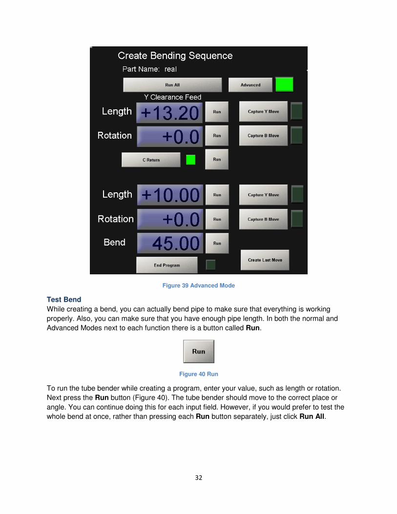
Advanced Mode
Advanced mode gives you more control of the machine. When the LED next to the Advanced
button is on, Advanced Mode is enabled. See the Figure 39 below.
Advanced Mode allows you to move the Y axis and rotate the B axis before returning the C axis.
In the second length and rotation entry, you can continue the Y axis motion and the B axis
motion to their final position for the next bend. The total move is the distance of both those
lengths /rotations added together. This can be used for avoiding collisions from the tube and
machine. The other input fields in Advanced Mode function the same as in Normal Mode.
32
Figure 39 Advanced Mode
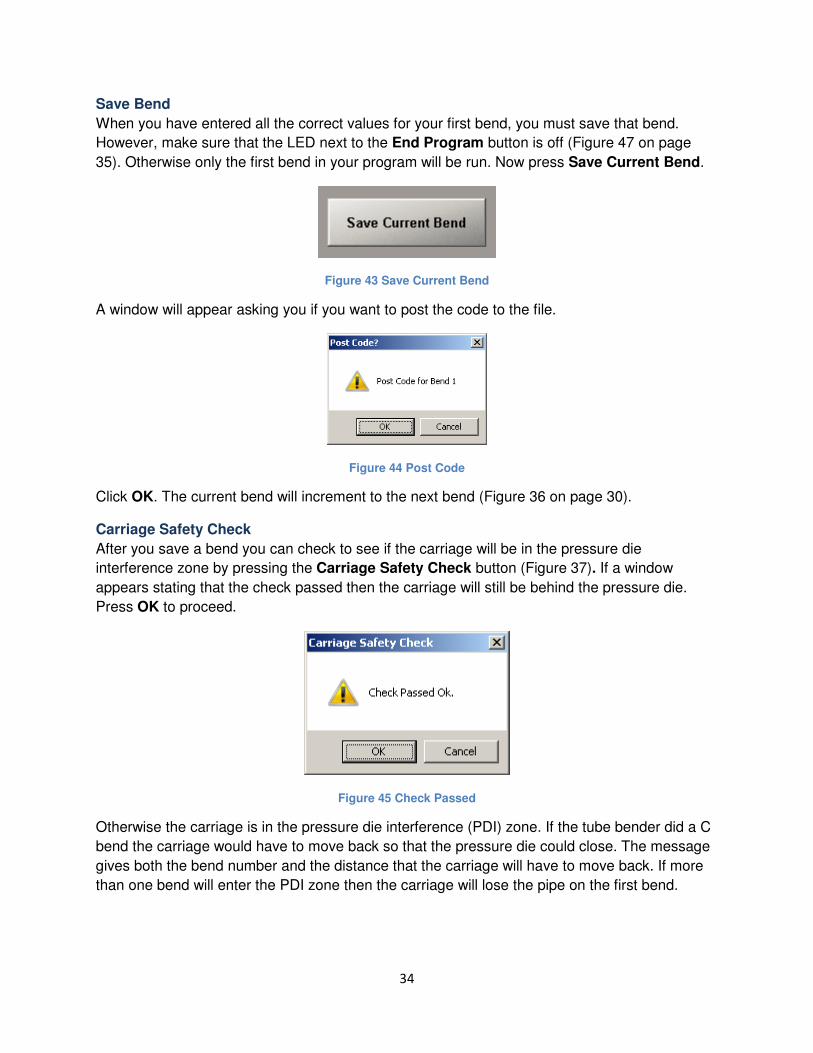
Test Bend
While creating a bend, you can actually bend pipe to make sure that everything is working
properly. Also, you can make sure that you have enough pipe length. In both the normal and
Advanced Modes next to each function there is a button called Run.
Figure 40 Run
To run the tube bender while creating a program, enter your value, such as length or rotation.
Next press the Run button (Figure 40). The tube bender should move to the correct place or
angle. You can continue doing this for each input field. However, if you would prefer to test the
whole bend at once, rather than pressing each Run button separately, just click Run All.

33
Figure 41 Run All
Note: Do not use the Run buttons in Y Axis Point to Point Bending.
****************************************************************************
DANGER:
Pressing the Run All button is equivalent to running a program. Stay clear of the
machine as every function may operate.
****************************************************************************
Capture Move
Another special feature for programming a bend is called Capture Move. This button is used to
capture or record a move. If you are figuring out the length to move forward before the C arm
returns, such as in an advanced move, you could use this feature. Also, if you are just creating a
bend for the first time, you can capture a move. To use it, do the following.
1. Click Capture Y Move or Capture B Move. The LED next to the button will turn on.
Figure 42 Capture Y Move
Jog the machine to the correct place. You can use the Run button or to manually jog each Axis,
click on the Jog button to the right of the Feed rate slider. Then, while holding the enable button
(green pushbutton switch to the left side of the control console), press + or – push buttons
(black pushbuttons on the operator’s panel). The axis will move as long as you hold the
buttons. Adjust the Jog Rate slider to control the speed.
2. Click Capture Y Move or Capture B Move button again. The LED next to the button will
turn off and the distance that you moved will be loaded into the input field next to the
button.
The Capture Move buttons record the initial position of the desired axis and then the final
position and writes the difference of the two into the corresponding input field.
34
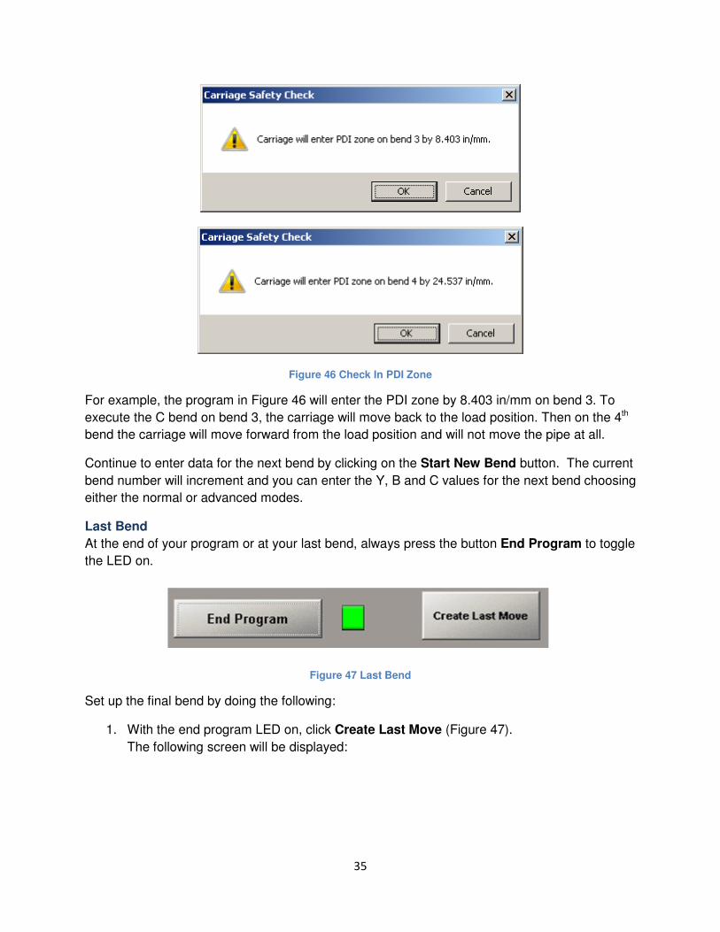
Save Bend
When you have entered all the correct values for your first bend, you must save that bend.
However, make sure that the LED next to the End Program button is off (Figure 47 on page
35). Otherwise only the first bend in your program will be run. Now press Save Current Bend.
Figure 43 Save Current Bend
A window will appear asking you if you want to post the code to the file.
Figure 44 Post Code
Click OK. The current bend will increment to the next bend (Figure 36 on page 30).
Carriage Safety Check
After you save a bend you can check to see if the carriage will be in the pressure die
interference zone by pressing the Carriage Safety Check button (Figure 37). If a window
appears stating that the check passed then the carriage will still be behind the pressure die.
Press OK to proceed.
Figure 45 Check Passed
Otherwise the carriage is in the pressure die interference (PDI) zone. If the tube bender did a C
bend the carriage would have to move back so that the pressure die could close. The message
gives both the bend number and the distance that the carriage will have to move back. If more
than one bend will enter the PDI zone then the carriage will lose the pipe on the first bend.
35
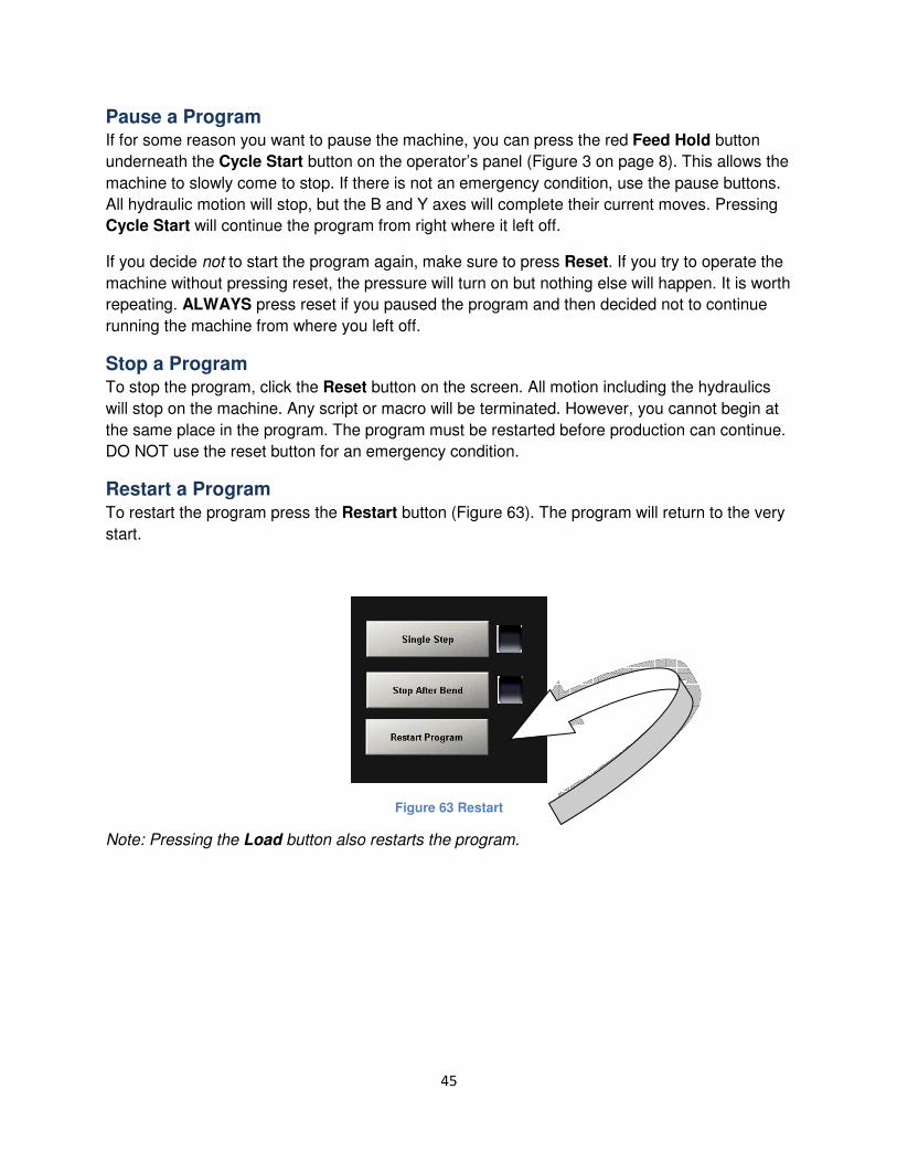
Figure 46 Check In PDI Zone
For example, the program in Figure 46 will enter the PDI zone by 8.403 in/mm on bend 3. To
execute the C bend on bend 3, the carriage will move back to the load position. Then on the 4th
bend the carriage will move forward from the load position and will not move the pipe at all.
Continue to enter data for the next bend by clicking on the Start New Bend button. The current
bend number will increment and you can enter the Y, B and C values for the next bend choosing
either the normal or advanced modes.
Last Bend
At the end of your program or at your last bend, always press the button End Program to toggle
the LED on.
Figure 47 Last Bend
Set up the final bend by doing the following:
1. With the end program LED on, click Create Last Move (Figure 47).
The following screen will be displayed:

36
Figure 48 End Program
2. Enter in the length you want the axis to move forward or backwards after the last bend.
3. Enter in the number of the degrees you want the part to rotate after the last bend.
(These values will allow moving the part to a more convenient position for unloading.)
4. Press the C Return button to toggle the LED on if you want the C axis to return.
5. Press the Release Collet button to toggle the LED on if you want to collet to release
when the program is done.
6. Enter the last Y length from the end of the last bend to the end of the part. This value is
used to calculate the required tube length.
7. Press Save.
You will now be back in the Bending Sequence page.
WARNING: Your last bend is not saved yet. Click save current bend to finish your
program.

37
All the programs are automatically stored in C:\Mach3\GCode. You can manually copy the files
to where ever you want for backup or file organization purposes. The file type is “.tap”.
Delete a Bend
At times when creating a program, you will need to delete a bend. You have two options.
Delete Last Bend To delete the last bend, click on the button Delete Last Bend.
Figure 49 Delete Last Bend
A small window will pop up asking you if you are sure that you want to delete that bend.
Figure 50 Delete Last Bend
Click OK. A window will pop up notifying you that the last bend was deleted. Again, click OK.
Figure 51 Bend Deleted
Delete All Bends If you want to start your program over, click Delete All Bends.

38
Figure 52 Delete All Bends
A window will pop up saying that the delete was successful. The program will revert back to
bend one.
Figure 53 Delete Successful
Disable a Bend
If you decide to you do not want to use a bend in the middle of a program, you can disable it by
clicking the Disable Bend button. The button toggles an LED and when the LED is on the bend
is disabled. Make sure to click Save Current Bend or the changes will not be implemented.
Figure 54 Disable Bend
Note: If you create a program and it does not do anything when you run it, make sure that the
disable bend LED is not on.
Change a Program
To change a program that is already loaded, simply click the Bending Sequence button (Figure
5 on page 8). You can make any changes you want in the part configuration. You must press
Save Configuration before leaving that screen for the changes to be saved.
After you press SAVE CONFIGURATION, Bending Sequence will come up. The current
program displayed will be one plus the number of bends. This last bend is NOT saved and is not
part of your program.

39
Change Previous Bend To change a previous bend click on Open Previous Bend.
Figure 55 Open Previous Bend
A window will pop asking you to choose a bend. Select your bend. Click OK.
Figure 56 Choose Bend
The screen is loaded with the values from that bend. Make your changes. Click Save Current
Bend and then at the prompt press OK.
When you are finished with your program, you can open Run Mode and your program will load
automatically. Your program should stay loaded until you close it or shut down the control.

40
This page was intentionally left blank.

41
Run Mode
In Run Mode you can execute your programs and bend tubing. This is where you will spend
most of your time. Almost everything is automatic in this mode. You can also test your programs
by running only segment of them at a time.
In this section you are going to learn how to open a program, step through a program, start and
stop a program, and much more. To begin, click on the Run Mode button (Figure 2 on page 7).
You will see the following screen:
Figure 57 Run Mode

42
Open a Program
Old Program To open an old program press Load Program.
Figure 58 Load Program
An open dialog will open (Figure 59). To open a specific file, navigate to its folder. All programs
are automatically stored in C:\Mach3\GCode. Change the type of file to (*.tap). Now you should
see all your bend programs. See Figure 59 below.
Figure 59 Open a File

43
Click on the correct program and press Open. Wait a moment as the program loads.
Recent Program To open a recent file, click on the Recent Program button.
Figure 60 Recent Program
It will open a window with a list of up to ten of the most recent files. Select a program to load
and press OK. Wait a moment as the program loads.
Figure 61 Select File to Load
Run a Program
Now with your program loaded, how do you start it? After starting a program you may need to
pause or restart it. Also, if this is the first time this file has been run you might want the program
to stop after every bend or after every line of code. If there is an emergency condition, you need
to know how to stop the machine. In this section you will learn how to do each of these things.

44
Start a Program To start a program, follow this procedure:
1. Press the Load button on the operator’s panel (Figure 3 on page 8). The control will
open the clamp and pressure die, move the carriage to load position and if not already
home, will return the bend arm.
*****************************************************************************
DANGER:
Stay clear of the machine. The C axis, pipe clamp, and pressure die will return
and the carriage may move.
****************************************************************************
2. Place a pipe in the machine.
3. Press the Collet button on the side panel (right below the Load button). The collet will
close.
4. Press the Enable button located on the left of the control console and at the same time
press the Cycle Start button on the operator’s panel. The file will begin to run.
****************************************************************************
DANGER:
Before pressing Cycle Start, move far away from the machine. Stay clear as long
as the machine is running. Every function of the machine may operate.
****************************************************************************
Figure 62 Control Buttons
45
Pause a Program If for some reason you want to pause the machine, you can press the red Feed Hold button
underneath the Cycle Start button on the operator’s panel (Figure 3 on page 8). This allows the
machine to slowly come to stop. If there is not an emergency condition, use the pause buttons.
All hydraulic motion will stop, but the B and Y axes will complete their current moves. Pressing
Cycle Start will continue the program from right where it left off.
If you decide not to start the program again, make sure to press Reset. If you try to operate the
machine without pressing reset, the pressure will turn on but nothing else will happen. It is worth
repeating. ALWAYS press reset if you paused the program and then decided not to continue
running the machine from where you left off.
Stop a Program To stop the program, click the Reset button on the screen. All motion including the hydraulics
will stop on the machine. Any script or macro will be terminated. However, you cannot begin at
the same place in the program. The program must be restarted before production can continue.
DO NOT use the reset button for an emergency condition.
Restart a Program To restart the program press the Restart button (Figure 63). The program will return to the very
start.
Figure 63 Restart
Note: Pressing the Load button also restarts the program.

46
Step through a Program If you are running a file for the first time you may want to step through the program one line at a
time. Press the Single Step button and the blue LED right next to it will begin to flash (Figure
64). Now every time you press cycle start, the control will only run one line of code.
Figure 64 Single Step
Program Display As a program is executed, you can view it on the top right hand corner of the screen (Figure 65).
Figure 65 Program Display
At the beginning of the program, information about your file is displayed. It shows you the part
number, the pipe dimensions, the die information, functions that are turned on, the spring back
values, and the operator’s safety distance. Farther down in the program it has the information
for the different bends. Notice that the first two lines of each bend contain a series of numbers.
These values store information for the bend.

47
Run One Bend at a Time When you are running a program for the first time, you may want to run more than one line at a
time, but still you do not want to run the whole program at once. To run only one bend at a time,
click on Stop After Bend (Figure 66). When the LED is on, only one bend will be run for every
time cycle start is pressed.
Figure 66 Stop After Bend
Emergency Stop In case of an emergency, press the large red EStop button on the operator’s panel (Figure 3 on
page 8). DO NOT PRESS FEED HOLD OR CYCLE STOP! The EStop button shuts down
power to everything but the control. All motion will stop immediately.
Note: Re-home the tube bender after an emergency condition.
Close a Program
To close a program click Close Program. See Figure 67 below.
Figure 67 Close Program

48
Run Functions
Other functions available in Run Mode are detailed below.
Cycle Start, Enable and Cycle Stop LED’s provide a visual feedback for the switches on the
operator’s console.
Program Time shows how long it has been since the last time cycle start was pressed (Figure
68 on page 48). This can give you an estimate of how long it will take to do a certain number of
parts.
Figure 68 Program Time
Feedrate Override Is used to control the overall speed of the axis motions. Y, B and C axes are
all controlled by the Feedrate Override slider.
Figure 69 Feedrate Override
Parts Needed and Parts Run are fields used to keep track of how many parts are needed for a production run and how many have been produced.

49
Shutting Down the Control
To power down your control, follow the steps outlined below.
1. Shut down the tube bender control software by clicking the exit button at the top right of the control. A window will pop up asking you if you are sure you want to end the session.
Figure 70 End Session
2. Click Yes. If another window pops up and asks you if you want to save the fixture, click Yes.
Figure 71 Fixture Save
3. Then click on the Start menu and then press Shut Down. The Mach Motion Tube Bender Control will turn off.
Note: Do not remove the power of the machine until the tube bender control is completely off.
50
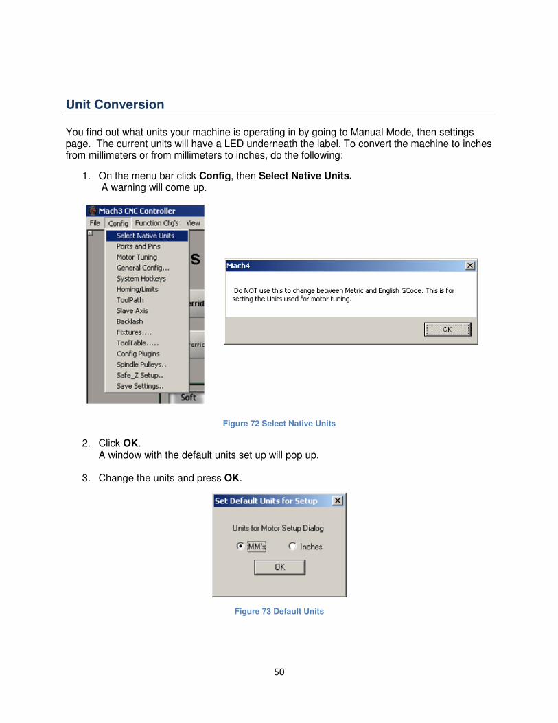
Unit Conversion
You find out what units your machine is operating in by going to Manual Mode, then settings page. The current units will have a LED underneath the label. To convert the machine to inches from millimeters or from millimeters to inches, do the following:
1. On the menu bar click Config, then Select Native Units. A warning will come up.
Figure 72 Select Native Units
2. Click OK. A window with the default units set up will pop up.
3. Change the units and press OK.
Figure 73 Default Units

51
4. Shut down the tube bender control software by clicking the exit button at the top right of the control. A window will pop up asking you if you are sure you want to end the session.
Figure 74 End Session
5. Click Yes. If another window pops up and asks you if you want to save the fixture, click Yes.
Figure 75 Fixture Save
6. Restart the tube bender control by double clicking on the icon on the desktop.
7. Click Home Machine (Figure 2 on page 7).
8. Click on the Manual Mode button and then click Settings. The LED next to the label of your desired unites should be on.
Figure 76 Convert Units
9. Click the Convert Units button ONLY ONCE (Figure 76)! More than once could mess up your machine. You will see a bunch of the values on the settings page change.
Your tube bender is now in the desired units.