tube clamps according to din 3015 - hansa-flex ag clamps according to din 3015 types of clamp bodies...
TRANSCRIPT


Tube clamps according to DIN 3015
Types of clamp bodies
The clamp bodies are available in these materials ex store– Polypropylene (dark green colour)– Polyamide (black colour)– Solid rubber (black colour)– Aluminium
Upper and lower clamp halves are identical. The inside of the clamp is available with or without webs.
Webs on the inside of the clamps have a vibration and impact reducing effect and absorb force towards the direction of the tube axis. A spacing between both halves produces the bias of the tube.
For the support of hoses and cables, we recommend to use clamps with an even inside without bias. The spacing measure s 1 is not required. Thus,the block height h 1 is reduced.
Types of metal parts
As a regular feature of the light and double series clamps, screws, rail nuts and cover plates are zinc coated,welding plates phosphatized and support rails uncoated.As a regular feature of the heavy series clamps, all steel parts are uncoated.All steel parts of the different construction series are also available ex stock in stainless steel type W5 and in rust-and acid-resisting stainless steel 1,4571 (AISI 316 Ti).Other surface treatments are available upon request.
UNC-threads are available upon request
Metric corresponding thread UNC-thread
M 6 1/4 – 20 UNC M 8 5/16 – 18 UNC M 10 3/8 – 16 UNC M 12 7/16 – 14 UNC M 16 5/8 – 11 UNC M 20 3/4 – 10 UNC M 24 7/8 – 9 UNC M 30 1 1/8 – 7 UNC
RegistrationGerman LloydLloyd’s Register of Shipping Bureau VeritasDET Norske VeritasRegistro Italiano Novale
Technical InformationHANSA-FLEX Tube Clamps

Mechanical Properties
Polypropylene (PP) Polyamide 6 (PA 6) Aluminium Rubber
Density 0,906 g/cm3 1,12 – 1,15 g/cm3 2,65 g/cm3 0,98 g/cm3
Flexural Deflection 36 N/mm2 130 ... 200 N/mm2 70 N/mm2 —
Impact Resistance no break no break — —
Compressive Strength 90 N/nm2 120 N/mm2 HB 500…600 N/mm2 shore
Modulus of Elasticity 1500 N/mm2 3000 N/mm2 70.0000 N/mm2 –
Tensile Strength 25 – 35 N/mm2 80 – 90 N/mm2 180 N/mm2 8,5 N/mm2
without reakage
Thermal Properties
Temp. Resistance – 30 up to + 90°C – 40 up to + 12O°C 300°C – 50 up to + 120°C
Chemical Properties
Weak Acids limited resistant limited resistant — resistant
Weak Alkalis limited resistant limited resistant — resistant
Alcohol resistant resistant — resistant
Petrol limited resistant resistant — limited resistant
Mineral Oils limited resistant resistant — resistant
Other Oils resistant resistant — resistant
Other materials on request.
The outlined particulars are approximate values and are only valid as references, which are not binding, also with regard to possible protection of third parties, and they do not exempt you from your own exam-ination of suitabillty of the products delivered by us.Therefore, these values can only be used in a limited sense for construction purposes.The application of the products is carried out outside our control possibilities and, therefore, is exclusive ly subject to your own area of responsibility.If, however, liability should be possible, it would be limited for all damages to the value of the goods supplied by us and in use by you.It goes without saying, that we guarantee the perfect quality of our products according to our general sales and delivery conditions.
Technical InformationHANSA-FLEX Tube Clamps

Assembly Instruction
Assembly on metal welding plates
Place welding plates on a base appropriate for the load. Make sure that the clamps are properly aligned. Clamp lower clamp halve onto welding plate, insert tube, place upper clamp halve onto lower halve and fasten with the screws. Attention must be paid to the bias (after completed assembly, clamp halves may not be in contact)! Do not weld with fitted plastic clamp!Extended welding plates may be screw-fastened to the base. Assembly on support rails
Assembly on support rails
Support rails are available in four different heights and come in pieces of 1 m or 2 m length, as required.Weld on support rail or screw-fasten with fastening angle bracket. Insert support rail nuts in rail and turn until stoppage. For heavy duty construction series, nuts are simply pushed in. Clamp lower clamp half on support rail nuts, insert tube, place upper clamp halve onto lower halve and fasten with the screws. Before fastening the screws,the clamp may still be positioned. Attention must be paid to the bias (after completed assembly,the clamp halves may not be in contact)!
Construction assembly
HANSA-FLEX Clamps allow the assembly of multiple clamps of the same construction size and of different tube diameters one above the other. The construction assembly is carried out with special fixing screws that are secured against twisting by applying a locking plate.Clamp lower clamp halve on welding plate or support rail respectively, insert tube, place upper clamp halve on lower halve and fasten with fixing screws. The fixing screw juts out from the upper clamp halve. The application of a locking plate securely fastens the fixing screw and prevents twisting. Clamp on second clamp halve on to the fixing screws etc.
Technical InformationHANSA-FLEX Tube Clamps

Screw Tightening Torque and axial Pipe Shearing Forces
The indicated srew tightening torque and axial pipe shearing forces refer to the assembly with cover plates and outside hexagon bolts according to DIN 931/933.The axial pipe shearing force (according to DIN 3015, part 10) is an average value, determined by three tests made with a steel pipe according to DIN 2448 of St 37, for which static friction is presupposed (temperature during tests: 23°C).When loading the HANSA-FLEX clamp with the indicated test force (F) in axial pipe direction, the pipe does not slide in the clamp.
Light series (DIN 3015, part 1)
Polypropylene Polyamide Aluminium
Screw Pipe Screw Pipe Screw Pipe tightening shearing tightening shearing tightening shearing Size Fixing screw torque (Mn) force F (kN) torque (Mn) force F (kN) torque (Mn) force F (kN)
0 M6 8 0,6 10 0,6 — —
1 M6 8 1,1 10 0,7 12 4,2
2 M6 8 1,2 10 0,8 12 4,3
3 M6 8 1,4 10 1,6 12 4,8
4 M6 8 1,5 10 1,7 12 5,0
5 M6 8 1,9 10 2,0 12 7,3
6 M6 8 2,0 10 2,5 12 8,9
Technical InformationHANSA-FLEX Tube Clamps

Heavy series (DIN 3015, part 2)
Polypropylene Polyamide Aluminium
Screw Pipe Screw Pipe Screw Pipe tightening shearing tightening shearing tightening shearing
Size Fixing screw torque (Mn) force F (kN) torque (Mn) force F (kN) torque (Mn) force F (kN)
1 M10 12 1,6 20 4,2 30 12,1
2 M10 12 2,9 20 4,5 30 15,1
3 M10 15 3,3 25 5,1 35 15,5
4 M12 30 8,2 40 9,3 55 29,4
5 M16 45 11,0 55 15,8 120 34,8
6 M20 80 14,0 150 21,0 220 50,0
7 M24 110 28,0 200 32,0 250 70,6
8 M30 180 40,0 350 48,0 500 84,5
Double series (DIN 3015, part 3)
Polypropylene Polyamide
Screw tightening Pipe shearing Screw tightening Pipe shearing Size Fixing screw torque (Mn) force F (kN) torque (Mn) force F (kN)
1 M6 5 0,9 5 0,9
2 M8 12 2,1 12 2,2
3 M8 12 1,9 12 2,0
4 M8 12 2,7 12 2,9
5 M8 8 1,7 8 2,5
Technical InformationHANSA-FLEX Tube Clamps
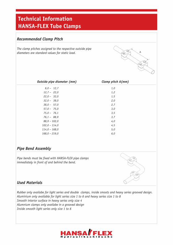
Recommended Clamp Pitch
The clamp pitches assigned to the respective outside pipe diameters are standard values for static load.
Outside pipe diameter (mm) Clamp pitch A(mm)
6,0 – 12,7 1,0 12,7 – 22,0 1,2 22,0 – 32,0 1,5 32,0 – 38,0 2,0 38,0 – 57,0 2,7 57,0 – 75,0 3,0 75,0 – 76,1 3,5 76,1 – 88,9 3,7 88,9 – 102,0 4,0 102,0 – 114,0 4,5 114,0 – 168,0 5,0 168,0 – 219,0 6,0
Pipe Bend Assembly
Pipe bends must be fixed with HANSA-FLEX pipe clamps immediately in front of and behind the bend.
Used Materials
Rubber only availabe for light series and double clamps, inside smoots and heavy series grooved design.Aluminium only available for light series size 1 to 6 and heavy series size 1 to 8Smooth interior surface in heavy series only size 4Alumnium clamps only availabe in a grooved designInside smooth light series only size 1 to 6
A
Technical InformationHANSA-FLEX Tube Clamps

Tube ClampsLight Construction Series

SRS 0108 L 0* 8 5/16
SRS 0110 L 0* 10 G 1/8
SRS 0112 L 0* 12
SRS 106 A L 1 6
SRS 108 A L 1 8 5/16
SRS 109,5 A L 1 9,5 3/8
SRS 110 A L 1 10 G 1/8
SRS 110,2 A L 1 10,2
SRS 112 A L 1 12
SRS 0213,5 L 2 13,5 G 1/4
SRS 0214 L 2 14
SRS 0215 L 2 15
SRS 0216 L 2 16 5/8
SRS 0217,2 L 2 17,2 G 3/8
SRS 0218 L 2 18
SRS 0320 L 3 20
SRS 0321,3 L 3 21,3 G 1/2
SRS 0322 L 3 22
SRS 0323 L 3 23
SRS 0325 L 3 25 1
*) only 1 screw
SRS-0100…Complete Clamps2 halves with short welding plate, screws and washers typ U
Material: Polypropylen
Light serie
Article category 9201
Clamp size 0
Designation Series Clamp size Ø Inch NB O.D.

SRS 0426,9 L 4 26,9 G 3/4
SRS 0428 L 4 28
SRS 0430 L 4 30
SRS 0532 L 5 32 1“1/4
SRS 0533,7 L 5 33,7 G 1
SRS 0535 L 5 35
SRS 0538 L 5 38 1“1/2
SRS 0540 L 5 40
SRS 0542 L 5 42 G 1“1/4
SRS 0542,4 L 5 42,4
SRS 0644,5 L 6 44,5 1“3/4
SRS 0645 L 6 45
SRS 0648 L 6 48 G 1“1/2
SRS 0648,3 L 6 48,3
SRS 0650 L 6 50
SRS 0652 L 6 52
SRS 0655 L 6 55
SRS 0657 L 6 57 2“1/4
Clamp size 1–6
SRS-0100…Complete Clamps2 halves with short welding plate, screws and washers typ U
Material: Polypropylen
Light serie
Article category 9201
Designation Series Clamp size Ø Inch NB O.D.

SRS 0106 DP L 0 6
SRS 0108 DP L 0 8 5/16
SRS 0110 DP L 0 10 G 1/8
SRS 0112 DP L 0 12
SRS 106 A-DP L 1 6
SRS 108 A-DP L 1 8 5/16
SRS 110 A-DP L 1 10 G 1/8
SRS 110,2 A-DP L 1 10,2
SRS 112 A-DP L 1 12
SRS 0213 DP L 2 12,7 1/2
SRS 0213,5 DP L 2 13,5 G 1/4
SRS 0214 DP L 2 14
SRS 0215 DP L 2 15
SRS 0216 DP L 2 16 5/8
SRS 0217,2 DP L 2 17,2 G 3/8
SRS 0218 DP L 2 18
SRS 0320 DP L 3 20
SRS 0321,3 DP L 3 21,3 G 1/2
SRS 0322 DP L 3 22
SRS 0323 DP L 3 23
SRS 0325 DP L 3 25 1
*) only 1 screw
Clamp size 0
SRS-0100…DPComplete Clamps2 halves with short welding plate, screws and washers typ U
Material: Polypropylen
Light serie
Article category 9200
Designation Series Clamp size Ø Inch NB O.D.

SRS 0426,9 DP L 4 26,9 G 3/4
SRS 0428 DP L 4 28
SRS 0430 DP L 4 30
SRS 0532 DP L 5 32 1“1/4
SRS 0533,7 DP L 5 33,7 G 1
SRS 0535 DP L 5 35
SRS 0538 DP L 5 38 1“1/2
SRS 0540 DP L 5 40
SRS 0542 DP L 5 42 G 1“1/4
SRS 0542,4 DP
SRS 0644,5 DP L 6 44,5 1“3/4
SRS 0645 DP L 6 45
SRS 0648 DP L 6 48 G 1“1/2
SRS 0648,3 DP L 6 48,3
SRS 0650 DP L 6 50
SRS 0652 DP L 6 52
SRS 0655 DP L 6 55
SRS 0657 DP L 6 57 2“1/4
Clamp size1–6
SRS-0100…DPComplete Clamps2 halves with short welding plate, screws and washers typ U
Material: Polypropylen
Light serie
Article category 9200
Designation Series Clamp size Ø Inch NB O.D.

SRS 0106 PP L 0 6 28 27 - 13,5
SRS 0108 PP L 0 8 5/16 28 27 - 13,5
SRS 0109,5 PP L 0 9,5 3/8 28 27 - 13,5
SRS 0110 PP L 0 10 G 1/8 28 27 - 13,5
SRS 0112 PP L 0 12 28 27 - 13,5
SRS 106 A PP L 1 6 34 27 20 13,5
SRS 108 A PP L 1 8 5/16 34 27 20 13,5
SRS 109,5 A PP L 1 9,5 3/8 34 27 20 13,5
SRS 110 A PP L 1 10 G 1/8 34 27 20 13,5
SRS 110,2 A PP L 1 10,2 34 27 20 13,5
SRS 112 A PP L 1 12 34 27 20 13,5
SRS 0213 PP L 2 12,7 1/2 40 33 26 16,5
SRS 0213,5 PP L 2 13,5 G 1/4 40 33 26 16,5
SRS 0214 PP L 2 14 40 33 26 16,5
SRS 0215 PP L 2 15 40 33 26 16,5
SRS 0216 PP L 2 16 5/8 40 33 26 16,5
SRS 0217,2 PP L 2 17,2 G 3/8 40 33 26 16,5
SRS 0218 PP L 2 18 40 33 26 16,5
SRS 0320 PP L 3 20 48 35 33 17,5
SRS 0321,3 PP L 3 21,3 G 1/2 48 35 33 17,5
SRS 0322 PP L 3 22 48 35 33 17,5
SRS 0323 PP L 3 23 48 35 33 17,5
SRS 0325 PP L 3 25 1 48 35 33 17,5
b
eca
Größe 0
bd
eca
Größe 1–6
Clamp Designation Series size Ø Inch NB O.D. b c d e
SRS-PP2 Clamp HalvesDIN 3015 Part 1
Material: Polypropylen
Light serie
Article category 9229

SRS SP 1 0 - 30
SRS SP 1 A 1 20 36
SRS SP 2 2 26 42
SRS SP 3 3 33 50
SRS SP 4 4 40 59
SRS SP 5 5 52 72
SRS SP 6 6 66 88
b
d
Größe 0
30
Größe 1–6
b
SRS-SPWelding Plates, shortDIN 3015 Teil 1
Light serie
Article category 9213
Designation Clamp size d b

SRS SP L 1 L 0 - 58 44
SRS SP L 1 A L 1 20 64 50
SRS SP L 2 L 2 26 70 56
SRS SP L 3 L 3 33 78 64
SRS SP L 4 L 4 40 87 73
SRS SP L 5 L 5 52 100 86
SRS SP L 6 L 6 66 116 100
fe
Größe 0
307
fe
d
Größe 1–6
SRS-SP LWeld / Screw Plates, longDIN 3015 Teil 1
Light serie
Article category 9214
Designation Series Clamp size d e f

SRS D SP 1 L 0 - 30 61
SRS D SP 1 A L 1 20 35 69
SRS D SP 2 L 2 26 43 86
SRS D SP 3 L 3 33 52 104
SRS D SP 4 L 4 40 60 117
SRS D SP 5 L 5 52 75 145
SRS D SP 6 L 6 66 90 176
d
a e
30SRS-D SPTwin Welding PlatesDIN 3015 Part 1
Light Serie
Article category 9215
Designation Series Clamp size d a e

SRS SP R 1 L 0 - 30 298
SRS SP R 1 A L 1 20 35 349
SRS SP R 2 L 2 26 43 427
SRS SP R 3 L 3 33 52 516
SRS SP R 4 L 4 40 60 297
SRS SP R 5 L 5 52 75 370
SRS SP R 6 L 6 66 90 446
d
ae
30SRS-SP RMultiple Welding PlatesDIN 3015 Teil 1
Light serie
Article category 9216
Designation Series Clamp size d a e

SRS TS 11-2 L 1–6 2 28 11 2 meters
SRS TS 14-2 L/D 1–6 2 28 14 2 meters
SRS TS 14-3 L 1–6 2 28 14 3 meters
SRS TS 30-2 L 1–6 2 28 30 2 meters
SRS TS 40-1 S 1–4 5 40 22 1 meters
SRS TS 40-2 S 1–4 5 40 22 2 meters
b
h
12
a
SRS-TSMounting RailsDIN 3015 Part 3
Article category 9210
Designation Series Clamp size a b h lenght

SRS SM D 1 12 20 22 5 M 6
SRS SM 30-50 S 1–3 18 25 20 7 M 10
SRS SM 60 S 4 20 25 23 8,5 M 12
SRS SM D D 2–5 14 20 22 11 M 8
h1
h2
a
12aM
d
SRS-SMRail NutsArticle category 9211
Designation Series Clamp size d a h1 h2 M

SRS DP 1 L 0 – –
SRS DP 1 A L 1 34 20
SRS DP 2 L 2 40 26
SRS DP 3 L 3 48 33
SRS DP 4 L 4 57 40
SRS DP 5 L 5 70 52
SRS DP 6 L 6 86 66
28
30
b
d
Größe 0Größe 1–6
SRS-DPCover PlatesDIN 3015 Part 1
Light serie
Article category 9208
Designation Series Clamp size B D
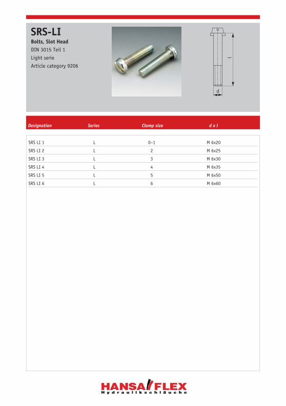
SRS LI 1 L 0–1 M 6x20
SRS LI 2 L 2 M 6x25
SRS LI 3 L 3 M 6x30
SRS LI 4 L 4 M 6x35
SRS LI 5 L 5 M 6x50
SRS LI 6 L 6 M 6x60
l
d
SRS-LIBolts, Slot HeadDIN 3015 Teil 1
Light serie
Article category 9206
Designation Series Clamp size d x l

SRS AS 1 L 0–1 M 6x30
SRS AS 2 L 2 M 6x35
SRS AS 3 L 3 M 6x40
SRS AS 4 L 4 M 6x45
SRS AS 5 L 5 M 6x60
SRS AS 6 L 6 M 6x70
l
d
SRS-ASBolts, Hexagon HeadDIN 3015 Part 1
Light serie
Article category 9203
Designation Series Clamp size d x l

SRS AS DP 1 L 0–1 M 6x30
SRS AS DP 2 L 2 M 6x35
SRS AS DP 3 L 3 M 6x40
SRS AS DP 4 L 4 M 6x45
SRS AS DP 5 L 5 M 6x60
SRS AS DP 6 L 6 M 6x70
l
d
SRS-AS DPBolts, Hexagon HeadDIN 3015 Part 1
Light Serie
Article category 9204
Designation Series Clamp size d x l

SRS AF 1 L 0–1 20 34
SRS AF 2 L 2 25 39
SRS AF 3 L 3 30 44
SRS AF 4 L 4 35 49
SRS AF 5 L 5 50 64
SRS AF 6 L 6 60 74
The use of stacking bolts neccessitates the deployment of locking plates during the construction assembly.
M6SW 11
12
b
a
M6
SRS-AFBolts, stackingDIN 3015 Part 1
Light serie
Article category 9207
Designation Series Clamp size a b

SRS SIL L 0–6 30 11
The use of stacking bolts neccessitates the deployment of locking plates during the construction assembly.
173,
5
SW
a
821 9,5
SRS-SILLocking PlatesDIN 3015 Teil 1
Light serie
Article category 9212
Designation Series Clamp size a SW

SRS SIS L 1–6 9 18
When assemblying solid rubber clamps, covering plates, hexagon screws and locking washers must be used.
b
aSRS-SISLocking WashersDIN 3015 Teil 1
Light serie
Article category 9212
Designation Series Clamp size a b

Tube ClampsHeavy Construction Series

SRS 3008 S 1 8 5/16
SRS 3010 S 1 10 G 1/8
SRS 3012 S 1 12
SRS 3012,7 S 1 12,7
SRS 3013,5 S 1 13,5 G 1/4
SRS 3014 S 1 14
SRS 3015 S 1 15
SRS 3016 S 1 16 5/8
SRS 3018 S 1 18
SRS 4020 S 2 20
SRS 4021,3 S 2 21,3 G 1/2
SRS 4022 S 2 22
SRS 4023 S 2 23
SRS 4025 S 2 25 1
SRS 4026,9 S 2 26,9 G 3/4
SRS 4028 S 2 28
SRS 4030 S 2 30
SRS 5030 S 3 30
SRS 5032 S 3 32 1“1/4
SRS 5033,7 S 3 33,7 G 1
SRS 5035 S 3 35
SRS 5038 S 3 38 1“1/2
SRS 5040 S 3 40
SRS 5042 S 3 42 G 1“1/4
SRS-30-80Complete Clamps2 halves with welding plate, screws
Material: Polypropylen
Heavy serie
Article category 9218
Designation Series Clamp size Ø Inch NB O.D.

SRS 3006 PP S 1 6 55 32 33 16 30
SRS 3008 PP S 1 8 5/16 55 32 33 16 30
SRS 3010 PP S 1 10 G 1/8 55 32 33 16 30
SRS 3012 PP S 1 12 55 32 33 16 30
SRS 3012,7 PP S 1 12,7 1/2 55 32 33 16 30
SRS 3013,5 PP S 1 13,5 G 1/4 55 32 33 16 30
SRS 3014 PP S 1 14 55 32 33 16 30
SRS 3015 PP S 1 15 55 32 33 16 30
SRS 3016 PP S 1 16 5/8 55 32 33 30 30
SRS 3018 PP S 1 18 55 32 33 16 30
SRS 4020 PP S 2 20 70 48 45 24 30
SRS 4021,3 PP S 2 21,3 G 1/2 70 48 45 24 30
SRS 4022 PP S 2 22 70 48 45 24 30
SRS 4023 PP S 2 23 70 48 45 24 30
SRS 4025 PP S 2 25 1 70 48 45 24 30
SRS 4026,9 PP S 2 26,9 G 3/4 70 48 45 24 30
SRS 4028 PP S 2 28 70 48 45 24 30
SRS 4030 PP S 2 30 70 48 45 24 30
SRS 5030 PP S 3 30 85 60 60 30 30
SRS 5032 PP S 3 32 1“1/4 85 60 60 30 30
SRS 5033,7 PP S 3 33,7 G 1 85 60 60 30 30
SRS 5035 PP S 3 35 85 60 60 30 30
SRS 5038 PP S 3 38 1“1/2 85 60 60 30 30
SRS 5040 PP S 3 40 85 60 60 30 30
SRS 5042 PP S 3 42 G 1“1/4 85 60 60 45 30
b
d
eca
f
SRS-30-80PP2 Clamp HalvesDIN 3015 Part 2
Heavy serie
Article category 9220
Clamp Designation Series size Ø Inch NB O.D. b c d e f

SRS 6038 PP S 4 38 1“1/2 115 90 90 45 45
SRS 6040 PP S 4 40 115 90 90 45 45
SRS 6042 PP S 4 42 G 1“1/4 115 90 90 45 45
SRS 6045 PP S 4 45 115 90 90 45 45
SRS 6048,3 PP S 4 48,3 G 1“1/2 115 90 90 45 45
SRS 6050 PP S 4 50 115 90 90 45 45
SRS 6052 PP S 4 52 115 90 90 45 45
SRS 6055 PP S 4 55 115 90 90 45 45
SRS 6060,3 PP S 4 60,3 G 2 115 90 90 45 45
SRS 6063 PP S 4 63 2“1/2 115 90 90 45 45
SRS 6065 PP S 4 65 115 90 90 45 45
SRS 6070 PP S 4 70 115 90 90 45 45
SRS 7070 PP S 5 70 152 120 122 60 60
SRS 7075 PP S 5 75 152 120 122 85 60
SRS 7076,1 PP S 5 76,1 G 2“1/2 3 152 120 122 85 60
SRS 7080 PP S 5 80 152 120 122 60 60
SRS 7088,9 PP S 5 88,9 G 3 3“1/2 152 120 122 60 60
SRS 7090 PP S 5 90 152 120 122 60 60
SRS 8090 PP S 6 90 205 170 168 85 80
SRS 8100 PP S 6 100 205 170 168 85 80
SRS 8101,6 PP S 6 101,6 G 3“1/2 4 205 170 168 85 80
SRS 8108 PP S 6 108 4“1/4 205 170 168 85 80
SRS 8114,3 PP S 6 114,3 G 4 4“1/2 205 170 168 85 80
b
d
eca
f
SRS-30-80PP2 Clamp HalvesDIN 3015 Part 2
Heavy serie
Article category 9220
Clamp Designation Series size Ø Inch NB O.D. b c d e f

SRS SP 30 S 1 33 30 73 8 M 10
SRS SP 40 S 2 45 30 85 8 M 10
SRS SP 50 S 3 60 30 100 8 M 10
SRS SP 60 S 4 90 45 140 10 M 12
SRS SP 70 S 5 122 60 180 10 M 16
SRS SP 80 S 6 168 80 225 15 M 20
b
d
Größe 0
30
Größe 1–6
b
SRS-SP 30-80Welding PlatesDIN 3015 Teil 2
Heavy serie
Article category 9221
Clamp Designation Series size d f g i m

SRS DP 30 S 1 55 33 30 8 11
SRS DP 40 S 2 70 45 30 8 11
SRS DP 50 S 3 85 60 30 8 11
SRS DP 60 S 4 115 90 45 10 14
SRS DP 70 S 5 152 122 60 10 18
SRS DP 80 S 6 205 168 80 15 22
i
M
f
b
d
SRS-DP 30-80Cover PlatesDIN 3015 Part 2
Heavy serie
Article category 9222
Clamp Designation Series size b d f i m

SRS AS 30 S 1 M 10x45
SRS AS 40 S 2 M 10x60
SRS AS 50 S 3 M 10x70
SRS AS 60 S 4 M 12x100
SRS AS 70 S 5 M 16x130
SRS AS 80 S 6 M 20x190
l
d
SRS-AS 30-80Bolts, Hexagon HeadDIN 3015 Part 2
Heavy serie
Article category 9223
Designation Series Clamp size d x l

SRS IS 30 S 1 M 10x45
SRS IS 40 S 2 M 10x60
SRS IS 50 S 3 M 10x70
SRS IS 60 S 4 M 12x100
SRS IS 70 S 5 M 16x130
SRS IS 80 S 6 M 20x190
l
d
SRS-IS 30-80Bolts, Socked HeadDIN 3015 Part 2
Heavy serie
Article category 9224
Designation Series Clamp size d x l

SRS AF 30 S 1 25 51 M 10 15
SRS AF 40 S 2 40 66 M 10 15
SRS AF 50 S 3 50 76 M 10 15
SRS AF 60 S 4 85 112 M 12 17
SRS AF 70 S 5 110 146 M 16 21
SRS AF 80 S 6 155 206 M 20 27
SWM
ab
M
SRS-AF 30-80Bolts, stackingDIN 3015 Part 2
Heavy serie
Article category 9225
Clamp Designation Series size a b m SW

SRS SIS 30 S 1 13 22
SRS SIS 40 S 2 13 22
SRS SIS 50 S 3 13 22
SRS SIS 60 S 4 15 28
SRS SIS 70 S 5 18 32
SRS SIS 80 S 6 21 36
When assemblying solid rubber clamps, covering plates, hexagon screws and locking washers must be used.b
aSRS-SISLocking WashersDIN 3015 Teil 1
Heavy serie
Article category 9212
Clamp Designation Series size a b

Tube ClampsDouble Series

SRS 106 D D/L 1 6
SRS 108 D D/L 1 8 5/16
SRS 110 D D/L 1 10 G 1/8
SRS 112 D D/L 1 12
SRS 214 D D/L 2 14
SRS 215 D D/L 2 15
SRS 216 D D/L 2 16 5/8
SRS 218 D D/L 2 18
SRS 320 D D/L 3 20
SRS 322 D D/L 3 22
SRS 325 D D/L 3 25 1
SRS 428 D D/L 4 28
SRS 430 D D/L 4 30
SRS 533,7 D D/L 5 33,7 G 1
SRS 535 D D/L 5 35
SRS 538 D D/L 5 38 1“1/2
SRS 542 D D/L 5 42 G 1“1/4
SRS-DTwin Tubes Complete Clamps2 clamps halves with welding plate, screws with hexagon head
Material: Polypropylen
Light serie
Article category 9231
Designation Series Clamp size Ø Inch NB O.D.

SRS 106 D PP D/L 1 6 36 27 20 13,5
SRS 108 D PP D/L 1 8 5/16 36 27 20 13,5
SRS 110 D PP D/L 1 10 G 1/8 36 27 20 13,5
SRS 112 D PP D/L 1 12 36 27 20 13,5
SRS 214 D PP D/L 2 14 53 26 29 13
SRS 215 D PP D/L 2 15 53 26 29 13
SRS 216 D PP D/L 2 16 5/8 53 26 29 13
SRS 218 D PP D/L 2 18 53 26 29 13
SRS 319 D PP D/L 3 19 3/4 67 37 36 18,5
SRS 320 D PP D/L 3 20 67 37 36 18,5
SRS 322 D PP D/L 3 22 67 37 36 18,5
SRS 325 D PP D/L 3 25 1 67 37 36 18,5
SRS 428 D PP D/L 4 28 82 42 45 21
SRS 430 D PP D/L 4 30 82 42 45 21
SRS 533,7 D PP D/L 5 33,7 G 1 106 54 56 27
SRS 535 D PP D/L 5 35 106 54 56 27
SRS 535/30 D PP D/L 5 35/30 106 54 56 27
SRS 538 D PP D/L 5 38 1“1/2 106 54 56 27
SRS 542 D PP D/L 5 42 G 1“1/4 106 54 56 27
b
ec
d
a2a1
SRS-D PP2 Clamp HalvesDIN 3015 Part 3
Material: Polypropylen
Article category 9232
Clamp Ø Designation Series size a1/a2 Inch NB O.D. b c d e

SRS SP 1 D 1 37 M 6
SRS SP 2 D 2 55 M 8
SRS SP 3 D 3 70 M 8
SRS SP 4 D 4 85 M 8
SRS SP 5 D 5 110 M 8
g
30
MSRS-SP-DWelding PlateDIN 3015 Teil 3
Heavy serie
Article category 9237
Designation Clamp size g m

SRS AS 1 D D/L 1 M 6x35
SRS AS 2 D D/L 2 M 8x35
SRS AS 3 D D/L 3 M 8x45
SRS AS 4 D D/L 4 M 8x50
SRS AS 5 D D/L 5 M 8x60
l
d
SRS-AS DBolts, Hexagon HeadDIN 3015 Part 3
Article category 9233
Designation Series Clamp size d x l

SRS IS 1 D D/L 1 M 6x35
SRS IS 2 D D/L 2 M 8x35
SRS IS 3 D D/L 3 M 8x45
SRS IS 4 D D/L 4 M 8x50
SRS IS 5 D D/L 5 M 8x60
l
d
SRS-IS DBolts, Socked HeadDIN 3015 Part 3
Article category 9234
Designation Series Clamp size d x l

SRS AF 1 D D/L 1 20 34 M 6 11
SRS AF 2 D D/L 2 20 33 M 8 12
SRS AF 3 D D/L 3 29 44 M 8 12
SRS AF 4 D D/L 4 34 49 M 8 12
SRS AF 5 D D/L 5 47 62 M 8 12
MSW
12
b
a
M
SRS-AF DBolts, stackingDIN 3015 Part 3
Article category 9235
Clamp Designation Series size a b M SW

SRS DP 1 D D/L 1 34 6,6
SRS DP 2 D D/L 2 51 8,6
SRS DP 3 D D/L 3 64 8,6
SRS DP 4 D D/L 4 78 8,6
SRS DP 5 D D/L 5 102 8,6
730
b
d
SRS-DP DCover PlatesLight serie
Article category 9236
Designation Series Clamp size b d

SRS SI 1D D 1 11
SRS SI 2D D 2–5 12
The use of stacking bolts neccessitates the deployment of locking plates during the construction assembly.
20
20,5
22
SW
1527
SRS-SILocking PlatesDIN 3015 Teil 3
Article category 9212
Designation Series Clamp size SW

SRS-SIS D 1 9 18
SRS-SIS 2D D 2–5 11 20
When assemblying solid rubber clamps, covering plates, hexagon screws and locking washers must be used.
b
aSRS-SISLocking WashersDIN 3015 Teil 1
Article category 9212
Designation Series Clamp size a b

HSRS25 25 52,5
HSRS30 30 55
HSRS35 35 57,5
HSRS38 38 59
HSRS42 42 61
HSRS hydraulik steel-clamps are mainly used in the field of building machinery.The support-block is welded to the machine body or another component either in upend or flatposition. The tube-clamp is screwed on.The robust construction of the clamp has an impact- and vibrationabsorbing effect. The small dimension/hight of the clamp allows hydraulic cables to be fitted later on – e.g. for installing additional equipment to building machinery.
50
15
80
40
255 ØD
31
12 AHSRSHydraulic Steel-clampsArticle category 9299
Designation Ø D A

SRS EP L
SRS ES S
SRS-ESleeves for Tube ClampsMaterial: Polypropylen
Article category 9209
Designation Series

22 Clamp Halves 13
2 Clamp Halves 29
2 Clamp Halves 30
2 Clamp Halves 39
BBolts, Hexagon Head 22
Bolts, Hexagon Head 23
Bolts, Hexagon Head 33
Bolts, Hexagon Head 41
Bolts, Slot Head 21
Bolts, Socked Head 34
Bolts, Socked Head 42
Bolts, stacking 24
Bolts, stacking 35
Bolts, stacking 43
CComplete Clamps 9
Complete Clamps 10
Complete Clamps 11
Complete Clamps 12
Complete Clamps 28
Cover Plates 20
Cover Plates 32
Cover Plates 44
HHSRS 47
Hydraulic Steel-clamps 47
LLight Construction Series 8
Locking Plates 25
Locking Plates 45
Locking Washers 26
Locking Washers 36
Locking Washers 46
MMounting Rails 18
Multiple Welding Plates 17
RRail Nuts 19
SSleeves for Tube Clamps 48
SRS-0100… 9
SRS-0100… 10
SRS-0100…DP 11
SRS-0100…DP 12
SRS-30-80 28
SRS-30-80PP 29
SRS-30-80PP 30
Index

SRS-AF 24
SRS-AF 30-80 35
SRS-AF D 43
SRS-AS 22
SRS-AS 30-80 33
SRS-AS D 41
SRS-AS DP 23
SRS-D 38
SRS-DP 20
SRS-DP 30-80 32
SRS-DP D 44
SRS-D PP 39
SRS-D SP 16
SRS-E 48
SRS-IS 30-80 34
SRS-IS D 42
SRS-LI 21
SRS-PP 13
SRS-SI 45
SRS-SIL 25
SRS-SIS 26
SRS-SIS 36
SRS-SIS 46
SRS-SM 19
SRS-SP 14
SRS-SP-D 40
SRS-SP 30-80 31
SRS-SP L 15
SRS-SP R 17
SRS-TS 18
TTube Clamps 8
Twin Tubes Complete Clamps 38
Twin Welding Plates 16
WWeld/ Screw Plates, long 15
Welding Plate 40
Welding Plates 31
Welding Plates, short 14
Index