tullaroop dam: embankment cracking and risk based ...€¦ · ancold 2006 conference page 1...
TRANSCRIPT
ANCOLD 2006 Conference Page 1
TULLAROOP DAM: EMBANKMENT CRACKING AND RISK BASED
ASSESSMENT OF REMEDIAL WORKS
G. Hunter
1 R. Fell
2 S. McGrath
3
ABSTRACT
The main embankment at Tullaroop Reservoir is a 42m high zoned earth and rockfill dam that was
constructed in the late 1950s. The constructed embankment has a very broad, well compacted clay
earthfill zone with dumped rockfill on the mid to lower upstream and downstream shoulders.
Over a two week period in April 2004 a diagonal crack of 60mm width and greater than 2m depth
developed on the downstream shoulder of the main embankment. The crack was located on the left
abutment and extended from the crest to the toe of the embankment. The diagonal crack terminated at
the downstream edge of the crest. A continuous longitudinal crack extended along the downstream
edge of the crest from the diagonal crack almost to the left abutment. Since April 2004 no further
widening of the diagonal crack has been observed.
This paper presents the findings of a series of site investigations and analysis to understand the
mechanism for formation of the diagonal crack, and the risk assessment process that culminated in the
eventual construction of a full height filter buttress on the left abutment of the main embankment.
Factors that influenced the cracking included the change in slope in the foundation profile, the
temporary diversion channel on the left abutment, residual stresses in the dam abutment due to
differential settlement during construction, a complex foundation geology and presence of shear
surfaces in a Tertiary alluvial sequence that formed due to valley formation, an historic dry period
and a prolonged period of drawdown. The presence of the crack and its assessed mechanism of
formation presented a dam safety risk of piping through the embankment. The risk evaluation process
was worked through with URS, Goulburn-Murray Water (G-MW), and G-MW’s expert panel, and
eventuated in construction of the localised filter buttress in February – March 2006 to address the
dam safety deficiency.
1 Principal Geotechnical Engineer, URS Australia Pty Ltd, Melbourne, VIC, Australia
2 Emeritus Professor, School of Civil and Environmental Engineering, University of New South Wales
3Manager Major Projects, Goulburn-Murray Water
Tullaroop Dam: Embankment cracking and risk based assessment of remedial works
ANCOLD 2006 Conference on Dams Page 1
1 INTRODUCTION
Tullaroop Reservoir is a 74,500 ML storage
located on Tullaroop Creek in central Victoria.
It supplies town water to Maryborough and
irrigation water to the local district. The dam
and appurtenant works were constructed in the
late 1950s. The main embankment is a zoned
earth and rockfill embankment of 42m
maximum height and 427m length (Figures 1
and 2).
Over a two week period in April 2004 a
diagonal crack of 60mm width and greater than
2m depth developed on the downstream
shoulder of the main embankment over the left
abutment. The crack extended from the crest
to the toe, terminating at the downstream edge
of the crest, but did not extend across the crest.
A continuous longitudinal crack extended
along the downstream edge of the crest from
the diagonal crack almost to the left abutment.
Since April 2004 no further widening of the
diagonal crack has been observed.
The diagonal crack formation is unusual for
this type of broad earthfill embankment. In
particular, the diagonal nature of the crack
itself, its time of observation after construction
(some 55 years), its formation over a period of
several weeks in April 2004 without further
movement thereafter. The authors are not
aware of a reported similar cracking
observation in a similar type embankment.
A series of investigations and analysis were
undertaken to understand the mechanism for
crack formation. The findings were used in a
risk assessment of piping failure modes
initiated by the presence of the crack. The risk
profile for Tullaroop Reservoir plotted above
the ANCOLD (2003) Limit of Tolerability for
existing dams with the risk of piping along the
crack contributing significantly to the risk
profile.
The first stage of risk reduction (undertaken
immediately following the risk workshop) was
to further update the Dam Safety Emergency
Plan and increase the surveillance levels at the
main embankment. The purpose of these
measures was to provide as early detection as
possible of seepage through the embankment,
stockpile materials in preparation for a dam
safety incident, thereby reducing the risk
profile as low as practicable in the very short
term.
The second stage of risk reduction was the
construction of a filter buttress on the left
abutment of the main embankment. The works
were started in February 2006 and practically
completed by March.
The paper presents details of the cracking
observations, key findings of the investigations
and analysis, and the two postulated
mechanisms for the cracking leading up to the
workshop. Additional observations during the
construction period are also presented, which
indicate the presence of a pre-existing shear
plane in the foundation contributing to the
failure mechanism (Crack Mechanism 2). The
risk profile before and after the filter buttress
construction is presented and the upgrade
works summarised.
2 GEOLOGY AND
EMBANKMENT HISTORY
Regional Geology Ordovician age sediments underlie the region
including the Tullaroop Reservoir. This is a
deep marine deposit comprising interbedded
sandstone and siltstone with minor shale and
chert. Cycles of erosion and deposition
including glaciation occurred until the Tertiary
age when alluvial deposits of clays, sands and
gravels infilled valleys. These deposits were
subsequently eroded, however some deposits
remain either as isolated outcrops or as “deep
lead” deposits buried by Early Quaternary
aged sheet and valley infill flows of olivine
basalt from multiple eruption points distributed
around the region.
Within the Tullaroop creek valley, Late
Quaternary aged flood plain deposits of gravel,
sand, silt and clay overlie the Ordovician
bedrock.
Geology on the Left Abutment of the Main Embankment The geological sequence on the left abutment
of the main embankment (Figure 3) consists of
a basalt cap overlying Tertiary alluvials in turn

Tullaroop Dam: Embankment cracking and risk based assessment of remedial works
ANCOLD 2006 Conference on Dams Page 2
overlying Ordivician sediments. The
Ordovician bedrock is dominantly siltstone
with interbedded sandstone units. It is steeply
dipping and tightly jointed, and on the left
abutment is extremely to highly weathered to
15 to 20m depth.
The Tertiary alluvium is a heavily over-
consolidated dominantly sandy and silty clay
of medium plasticity (but variable) of hard
strength consistency and fissured. Deposits of
clayey to gravely sand and gravely clay are
much less frequent. On the left abutment, the
Tertiary alluvium reflects deposition within a
minor tributary to a larger north flowing river.
The embankment is positioned over this broad
minor tributary and therefore a relatively thick
deposit of Tertiary alluvium is present in the
foundation on the left abutment.
There is evidence of pre dam landslide activity
on the left abutment of the main embankment
and is consistent with the geomorphologic
evolution of the valley. This was likely
formed by undercutting from the Tullaroop
creek removing the relatively softer
Ordovician and Tertiary alluvium, resulting in
over-steepening and landsliding. A large and
old landslide feature extending back into the
basalt capping is likely present upstream of the
embankment, but was assessed as not likely to
extend beneath the embankment.
Site investigations intersected and original
drawings showed up to several metres of
colluvium on the left abutment at the
embankment location. This colluvium would
likely be formed by landslide activity and
would therefore suggest a series of shallow
landslides within the Tertiary alluvium in the
region now occupied by the embankment.
Main Embankment The main embankment is a zoned earth and
rockfill embankment of 42m maximum height
(Figures 1 and 2, Plates 1 and 2). It has a very
broad central earthfill zone with rockfill zones
at the outer upstream and downstream toe
regions. Transition zones of rounded quartz
gravel separate the earthfill and rockfill zones.
The earthfill consists of sandy clay and clay of
low to medium plasticity. It was borrowed
locally from colluvial soils and residual soils
derived from the Ordovician sedimentary
formation. It was placed on the dry side of
optimum and compacted using sheepsfoot
rollers to produce a well compacted earthfill.
Basalt for the rockfill zones was sourced from
the spillway excavation and a nearby quarry
area. The basalt was dumped in layers, spread
and trafficked by dozers and haul trucks.
Investigations encountered a dirty rockfill in a
loose condition comprising basalt boulders
within a clayey gravel matrix.
Plate 1. Downstream shoulder of Tullaroop
Dam
Plate 2. Upstream shoulder of Tullaroop
Dam
A temporary diversion channel was cut into the
left abutment of the main embankment (Figure
3). It was formed within the Ordovician
sediments with a cut height of 9 to 10m and
battered at 50 degrees. Earthfill levels on the
dam side of the diversion channel reached 10m
above invert level before the diversion channel
was filled in early 1959.
Tullaroop Dam: Embankment cracking and risk based assessment of remedial works
ANCOLD 2006 Conference on Dams Page 3
Foundation Preparation The alluvium from the valley floor was
removed (by dragline) to expose the
underlying weathered Ordovician bedrock.
Stripping by scraper was undertaken on the hill
slopes. Stripping over the Tertiary alluvium
was typically in the order of 2 to 3m according
to the as constructed drawings.
It was not clear from the historical records if
the colluvium overlying the Tertiary alluvium
was removed during stripping. Investigations
(URS 2005a) confirmed the presence of
several metres of colluvium below the
embankment on the left abutment region. In
addition, during the construction works in
2006, several slickensided slide planes were
encountered within the Tertiary alluvial
foundation. These were assessed as remnant
from shallow landslide features that were not
removed during stripping. Further details are
given in Section 7.
3 HISTORY OF CRACKING
AND CRACK
OBSERVATION
The history of cracking and defect
observations was sourced through Goulburn-
Murray Water (G-MW) records, mainly visual
inspection reports, dating back to 1987.
Cracking on the main embankment has been
reported back to as early as 1988, but probably
pre-dates this.
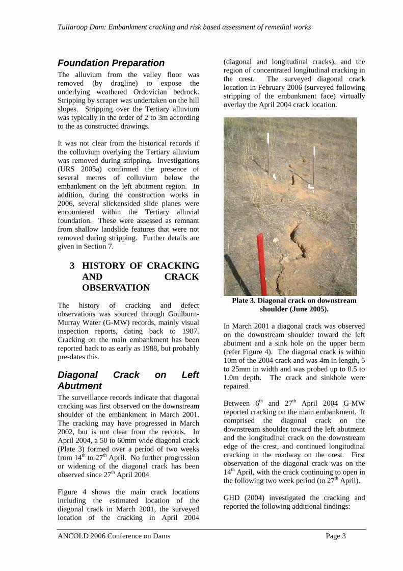
Diagonal Crack on Left Abutment The surveillance records indicate that diagonal
cracking was first observed on the downstream
shoulder of the embankment in March 2001.
The cracking may have progressed in March
2002, but is not clear from the records. In
April 2004, a 50 to 60mm wide diagonal crack
(Plate 3) formed over a period of two weeks
from 14th to 27
th April. No further progression
or widening of the diagonal crack has been
observed since 27th April 2004.
Figure 4 shows the main crack locations
including the estimated location of the
diagonal crack in March 2001, the surveyed
location of the cracking in April 2004
(diagonal and longitudinal cracks), and the
region of concentrated longitudinal cracking in
the crest. The surveyed diagonal crack
location in February 2006 (surveyed following
stripping of the embankment face) virtually
overlay the April 2004 crack location.
Plate 3. Diagonal crack on downstream
shoulder (June 2005).
In March 2001 a diagonal crack was observed
on the downstream shoulder toward the left
abutment and a sink hole on the upper berm
(refer Figure 4). The diagonal crack is within
10m of the 2004 crack and was 4m in length, 5
to 25mm in width and was probed up to 0.5 to
1.0m depth. The crack and sinkhole were
repaired.
Between 6th and 27
th April 2004 G-MW
reported cracking on the main embankment. It
comprised the diagonal crack on the
downstream shoulder toward the left abutment
and the longitudinal crack on the downstream
edge of the crest, and continued longitudinal
cracking in the roadway on the crest. First
observation of the diagonal crack was on the
14th April, with the crack continuing to open in
the following two week period (to 27th April).
GHD (2004) investigated the cracking and
reported the following additional findings:

Tullaroop Dam: Embankment cracking and risk based assessment of remedial works
ANCOLD 2006 Conference on Dams Page 4
1) On the downstream shoulder the crack was
up to 50mm to 60mm wide at the surface and
was probed to 1.8m depth at several locations.
2) In test pits excavated over the crack, it was
observed that the crack width had reduced to 1
to 2mm below 1.3m where exposed.
3) No shearing type movement was observed
either vertically or laterally along the crack.
The crack was effectively a tension type
feature.
4) The direction of movement of the diagonal
crack on the upper berm was at 40 degrees to
the dam axis (refer Figure 4). This direction is
close to perpendicular to the alignment of the
crack.
5) The crack is rough and irregular.
6) At the junction of the diagonal crack and
downstream edge of the crest the crack was
observed to 0.6m depth then continued as a
30mm wide softened zone to 1.5m depth.
Other Notable Cracking Observations Apart from the diagonal crack observations
described above, the most notable cracking has
been longitudinal cracks on the crest and
downstream shoulder of the embankment.
Longitudinal cracking in the crest roadway
have been observed since at least the 1980s.
Whilst cracking is present along the length of
the crest, it is concentrated on the left abutment
(refer Figure 4). Since the installation of
temporary survey targets in 2004, lateral
spreading of the crest is notable in this area of
concentrated longitudinal cracking.
GHD (2004) excavated a test pit in the
embankment crest over a longitudinal crack
and reported that the crack extended to depths
in excess of 1.5 to 2m (crack widths of 1 to
2mm persisted to the 2m depth of the
excavation); sand wash into the crack and
bitumen runs from sealing was evident; the
crack was slightly inclined off vertical to
upstream; its surface varied from smooth and
planar to irregular; and no signs of shearing
along the crack were observed.
The longitudinal cracking on the downstream
shoulder has been observed along the
embankment. The cracking typically follows
significant periods of low rainfall, generally
over summer to autumn, with crack
observations typically in the period from
March to June. These cracks usually close up
following rainfall.
Minor tranverse cracks are also present in the
embankment crest. These cracks are typically
less than 1mm wide and of limited depth (0.3
to 0.6m) as reported by GHD (2004).
4 PROPERTIES OF
EARTHFILL
The very broad earthfill zone consists of sandy
clay and clay of low to medium plasticity and
of very stiff to hard strength consistency.
Particle size distributions show the fines
content (minus 75 micron) ranges from 40 to
94% and clay fractions (minus 2 micron) from
7 to 56%. Shrink swell indices range from 0.9
to 2.1% and linear shrinkage from 3 to 12.5%,
indicating the earthfill is typically of low
reactivity, but does contain some moderately
reactive clays.
Hole erosion tests indicate the rate of the
erosion is Moderately Slow according to the
UNSW Classification System (Fell et. al,
2004). Pin hole and Emerson class tests
indicate the earthfill is non dispersive in
reservoir water, but slightly dispersive in
distilled water.
The moisture content profile of the earthfill in
the downstream shoulder (from 2004
investigation results) shows substantial drying
in the upper 1.5 to 2m. The moisture content
in this region is well dry of the average
moisture content at placement and Standard
Optimum moisture content reflecting the dry,
hard and desiccated condition of the earthfill in
this region.
Under the sealed crest of the embankment the
extent of drying is not as extensive, although
moisture contents in the upper 2m are 2 to 4%
below the average moisture content at
placement. This variation in moisture content
between the crest and downstream shoulder is
due to the pavement capping the crest.
On the upstream face, the earthfill below the
upstream rockfill surfacing was in a moist to
very moist and firm to stiff condition. This
region was significantly wetter than that
Tullaroop Dam: Embankment cracking and risk based assessment of remedial works
ANCOLD 2006 Conference on Dams Page 5
encountered elsewhere in the embankment.
No diagonal or transverse cracks were
observed in the excavated upstream face on the
left abutment (Excavation 1, Figure 1).
5 DAM SURVEILLANCE
Reservoir Operation Figure 5 presents the reservoir operation for
Tullaroop from first filling through to March
2005. Also shown is the annual rainfall. The
reservoir is subjected to an annual cycle of
drawdown and re-filling, with drawdown
during the summer to winter period and re-
filling during the winter to spring period. Up
until 1997 the reservoir was generally operated
above RL 214m AHD and subject to an annual
drawdown up to 7 to 9 metres.
Since 1997 the reservoir has been at a
sustained drawn down level, generally
operated below RL 215m AHD. The
minimum reservoir level of RL 208.61m AHD
was reached in June 2004. This period
corresponds with the sustained drought period
in Victoria (6 of 8 years from 1997 to 2004 of
below average rainfall) and to the driest period
in recorded history in the Maryborough area
(126 years of records).
Piezometers A total of 35 piezometers have been installed
in the main embankment at Tullaroop. All
were virtually dry prior to first filling. On
establishing equilibrium conditions after first
filling, the piezometers show a gradual
reduction in piezometric level across the broad
earthfill zone. A number of piezometers at the
higher elevations, particularly those in the
downstream shoulder, are dry.
The piezometers respond to fluctuations in
reservoir level. Those piezometers in the
upstream shoulder have the shortest lag and the
higher amplitude of response to change.
Under the downstream shoulder the
piezometers show a general long-term trend
and do not appear to respond to short term
fluctuations.
From pre 1997 to 2005, the reduction in
piezometric level in the central to downstream
section of the earthfill has been small at less
than approximately 10 to 20 kPa. The
standpipe piezometers installed in the left
abutment in November 2004 have been dry
since installation.
Embankment Deformation Behaviour In general, the post construction deformation
behaviour of the crest and downstream
shoulder of the main embankment are
consistent with the general trends for similar
type embankments. The trend of the
settlement and displacement show a gradually
decreasing rate of settlement and downstream
displacement with time (time on normal scale).
Long-term settlement rates range from 0.23 to
0.53% for the crest points and downstream
shoulder, and are within the expected range.
Since the mid 1990s, lateral displacements
have virtually stopped; in fact several points
show a small and gradual displacement to
upstream (total displacement to upstream of
less than 5 to 10mm).
Tullaroop ReservoirPost construction settlement of ES2 at Chainage 204m
(maximum section)
0
5
10
15
20
25
30
35
40
45
0 25 50 75 100 125 150 175 200 225
Post Construction Settlement (mm)
Dep
th B
elo
w C
res
t (m
)
9-Feb-61
1-Apr-63
15-Mar-68
30-Nov-76
19-Jun-81
1-Nov-84
24-May-96
24-Apr-01
15-Dec-04
crest
End of construction on
18 May 1959
foundation level
First reading
after first filling
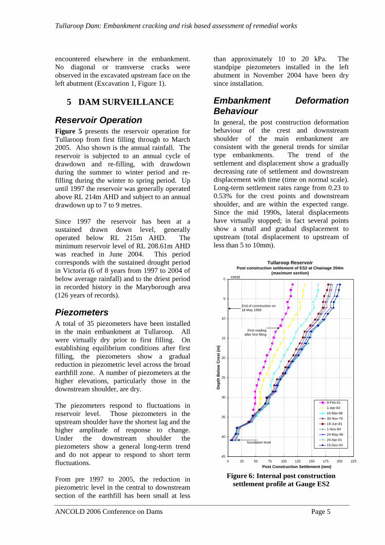
Figure 6: Internal post construction
settlement profile at Gauge ES2

Tullaroop Dam: Embankment cracking and risk based assessment of remedial works
ANCOLD 2006 Conference on Dams Page 6
The two internal settlement gauges also show a
trend consistent with similar type
embankments and “normal” type deformation
behaviour. Figure 6 is from the settlement
gauge at the maximum section and shows a
total settlement of approximately 200mm since
end of construction. Close to 60% of this
occurred during first filling in 1959/60 and
90% by 1981. During the prolonged drought
period (from 1997), total settlements were less
than 5mm.
6 FACTORS INFLUENCING
CRACK FORMATION
A number of possible contributing factors were
evaluated as part of the assessment of
mechanics of crack formation, and these are
discussed in the following sub-sections.
Embankment Deformation Under Sustained Drawdown The surface deformation and internal
settlement profiles (Figure 6) show only small
deformations during the sustained period of
drawdown from 1997. It was assessed
therefore, that embankment deformation under
sustained drawdown had a negligible
contribution to the formation of the diagonal
crack.
However, a possible contributing factor could
be localised higher deformation in the area of
the diversion channel on the left abutment
attributed to a lesser quality of earthfill
placement in the restricted working area and
the short time for placement. The nearest
settlement point (located on the dam side of
the diversion channel) recorded no
significantly greater deformation.
Shrink and Swelling of Earthfill There are a number of factors that point toward
shrinkage and swelling of the earthfill as
having some influence on the diagonal crack
observation. These include the low to
moderate reactivity of the earthfill, the
substantial drying in the upper 1.5 to 2m depth
of the downstream shoulder, the reduction in
crack width below about 1.3m, and opening
and closing of cracks depending on climatic
conditions.
The seasonal deformation behaviour of the
temporary survey points on the left abutment
(from April 2004 to late 2005) shows a
cyclical pattern of deformation. Deformation
in seasonally drier periods is into the plane of
the downstream face (settlement and upstream
displacement) and out of the plane of the
downstream face in seasonally wetter periods
(upward and downstream displacement). This
cyclical response to climatic conditions is
assessed as reflecting seasonal shrinkage and
swelling of the earthfill.
The observation of the reduction in crack
width below the upper zone of significant
drying was assessed as confirmation that
shrinkage and swelling of the earthfill was a
factor in the crack formation. Also, the
reduced drying below the crest and moist
condition below the upstream shoulder could
partly be the reason why the crack had not
progressed across the crest. However, on its
own shrink-swell does not fully explain the
observed cracking (i.e. why a diagonal crack
on the left abutment as observed).
During the construction works in 2006 when
the outer face of the embankment was exposed
and further excavation along the crack was
performed, it was evident that the crack width
persisted to greater depth than initially thought.
This is discussed further in Section 7.
Landslide on the Left Abutment The formation of landslides in the left
abutment prior to dam construction is
consistent with the geomorphologic evolution
of the valley and there is evidence of pre dam
landslide activity on the left abutment as
discussed in Section 2. However, it was
assessed that deep seated mass instability of
the left abutment was not likely to be a
contributing factor to the crack mechanism.
It was assessed as possible that pre-existing
slide planes from shallow landslips in the
Tertiary alluvium or weathered Ordovician
units could be present below the embankment.
The shallow stripping in this area may not
have removed these potential shear surfaces
thereby leaving a potential plane of weakness
within the Tertiary alluvium at close to the

Tullaroop Dam: Embankment cracking and risk based assessment of remedial works
ANCOLD 2006 Conference on Dams Page 7
embankment interface above the steepened cut
section of the former diversion channel.
This mechanism was considered as a
contributing factor in the mechanics of the
crack formation and included in the risk
assessment.
During the construction works several pre-
existing shear surfaces were observed within
the Tertiary alluvium on the left abutment
(Section 7). These observations provide strong
evidence that the presence of pre-existing
shear surfaces in the foundation are a
significant contributing factor in explaining the
crack mechanism.
Change in Foundation Slope on the Left Abutment Excavation for the temporary diversion culvert
resulted in a steep step in the foundation
profile from upstream to downstream across
the embankment. As shown in Figure 3, the
diagonal crack is located above this change in
slope.
Numerical modeling was undertaken to
evaluate the potential for development of
tensile stresses within the earthfill during
construction due to the change in slope on the
left abutment. A 2-dimensional model of the
embankment construction (in long section) was
undertaken using the computer program
DIANA (modeling by NSW Department of
Commerce). Embankment construction was
modeled in 10 stages and the staging of works
around the temporary diversion channel.
The modeling showed that a zone of reduced
minor principal stress over the change in
abutment slope. In some cases a small tensile
stress was observed on the crest of the
constructed layer. The zone of reduced
compressive stress to low tensile stress from
the numerical analysis is shown on Figure 3.
The results of the modeling show that the
change in slope of the left abutment does
reduce the minor principal stress within the
earthfill as construction proceeds. However,
the stresses are generally still compressive.
The small to negligible formation of tensile
stress above the change in slope was possibly
due to the relatively low height of the steep
section of slope. The results indicate that a
tensile crack is unlikely to have formed during
embankment construction.
Post construction deformation across the
change in slope was estimated to be in the
range 75 to 95mm from the internal settlement
gauge records (note, the gauges are located at
the maximum section and on the right
abutment). Most of this differential settlement
would have occurred in the period of first
filling.
Although not modelled numerically, the post
construction differential settlement is likely to
further reduce the compressive stress over the
change in slope, and possibly result in the
formation of tensile stress in the outer slope of
the embankment. Longitudinal strains on the
embankment crest would be expected to be
tensile in the zone directly over and upslope of
the change in slope and compressive below the
change in slope, much the same as was
modelled during construction.
Another factor to consider in the potential for
tensile stress formation is the properties of the
earthfill itself. The low to medium plasticity
earthfill was placed on the dry side of optimum
and would potentially be relatively brittle.
In summary, the numerical modelling showed
the formation of a zone of reduced minor
principal stress over the change in abutment
slope, and minor tensile stress formation. Post
construction deformations are likely to have
further reduced the stresses in this area. It is
postulated that these stress conditions have
been effectively “locked in” since construction
and the period of significant post construction
settlement.
Foundation Compressibility Compressibility of the foundation was ruled
out as a possible contributing factor given the
heavily over-consolidated nature of the
Tertiary alluvium.

Tullaroop Dam: Embankment cracking and risk based assessment of remedial works
ANCOLD 2006 Conference on Dams Page 8
7 OBSERVATIONS DURING
CONSTRUCTION WORKS
IN 2006
Crack Mapping After stripping the downstream face of the
embankment, the diagonal crack on the
embankment was mapped and surveyed.
Figure 7 shows the surveyed crack location.
The separation between the mapped crack on
the upper and mid slopes of the shoulder is
because this is the location of one of the test
pits. The lower termination position of the
crack is because filter had been placed to this
elevation.
Plate 4 shows the crack on the mid slope
(above the embankment toe) at an estimated
depth of 2 to 2.5m below the original
embankment surface. At this depth the crack
was continuous and its width measured at 5 to
10mm.
Plate 4. Crack in mid slope
Along the downstream edge of the crest the
excavation was 1.5m deep, and at this depth
there was no trace of the longitudinal crack as
mapped on the surface (refer Figure 3).
Plates 5 and 6 show the diagonal crack on
upper slope. Towards the crest of the
embankment the crack was discontinuous
(Plate 5) and the angle of the crack to the dam
axis decreased as the crest is approached. As
shown, the surface of the crack was irregular
and rough. No evidence of shear movement
was observed.
Plate 5. Crack in upper slope within 5m of
the crest
Plate 6. Crack in upper slope (mid to lower
section)
crack

Tullaroop Dam: Embankment cracking and risk based assessment of remedial works
ANCOLD 2006 Conference on Dams Page 9
Sections of the diagonal crack on this upper
slope were then excavated locally to
approximately 1m depth to further assess the
extent of cracking with depth and to remove
longitudinal cracking from around the main
crack. The crack was clearly visible in the
base of the excavated section on the upper
slope (approximately 1.5m below the original
embankment surface). At these depths the
crack was measured at 10-15mm width,
occasionally up to 40mm. The crack was
probed with a 12mm reinforcement rod to
depths from 0.3m (near crest) up to 1.5m depth
(lower end of the crack in Plate 6).
These findings indicate that the crack is
persistent at depth. Crack widths of 5 to
15mm persist to depths of 2.5 to 3.0m below
the original embankment surface. At these
depths, the crack is open below the region of
drying. Previously it was thought that the
crack narrowed to less than 1 to 2mm below
the upper zone of drying. Therefore, the
significance of shrinkage and swelling of the
earthfill is not as great as previously evaluated.
Slip Surfaces in Tertiary Alluvium Part of the upgrade works involved a 2 to 2.5m
deep excavation along the downstream toe of
the embankment on the left abutment. Two
slide planes (Slide Plane 1 and Slide Plane 2)
were observed in the Tertiary alluvium within
this excavation. Test pitting was undertaken
along the upstream toe of the embankment on
the left abutment. A slide plane (Slide Plane
3) was observed within this excavation and
was at similar elevation to Slide Plane 1. The
location, orientation and measured dip of these
surfaces is shown in Figure 7. Figure 8
presents a section showing the location of
Slide Plane 1 and 3.
All three slide planes were oriented near
normally to the natural slope, the slide surface
dipped into the slope at a low angle (0 to 6
degrees) and the plane of movement (evident
from slickensides and striations) was out of the
slope.
Slide Plane 1 (Plate 7 and 8) was observed in
the Tertiary alluvium at the contact between a
layer of light grey high plasticity clay and the
lower zone white friable sandy clays. It was
continuous across the excavation and exposed
in the side of the excavation (Plate 8), the
surface was polished and slickensided, there
was no evidence of self healing as the surface
was readily separated by hand along the slip
plane. The surface was slightly undulating
normal to the direction of movement.
Slide Plane 3 (Plate 9) had similar attributes to
Slide Plane 1. Slide Plane 2 was less
developed than either 1 or 3.
Plate 7. Slide Plane 1
Plate 8. Slide Plane 1
Plate 9. Slide Plane 3
Dip 6
Direction of
movement
Direction of
movement

Tullaroop Dam: Embankment cracking and risk based assessment of remedial works
ANCOLD 2006 Conference on Dams Page 10
Inclinometer INC01 was installed in the crest
of the embankment (refer Figure 7 for its
location). Continuous tube sampling was
successfully undertaken across the elevation
interval of Slide Plane 1 and 3; however, no
sign of a shear surface was observed in the
extruded samples.
8 MECHANICS OF CRACK
FORMATION
Following the investigations and prior to the
risk workshop, two potential mechanisms were
postulated for the development of the observed
diagonal crack. Subsequent to the findings
during the construction works, Crack
Mechanism 2 is now considered the most
likely mechanism.
Crack Mechanism 1 Crack Mechanism 1 is a combination of the
tensile stress formation due to the change in
slope and shrink-swell. The events resulting in
the formation of the diagonal crack were
postulated as follows (Figure 9):
1) Formation of a “locked in” zone of reduced
compressive stress within the earthfill and
tensile stress formation in the outer slope of
the earthfill across the change in slope. These
stress conditions resulted from differential
settlement across the change in slope during
and post construction and were present well
before the observation of the cracking in April
2004;
2) The prolonged dry period since 1997 has
resulted in the observed drying of the earthfill
in the downstream shoulder to 1.5 to 2m depth
(this is potentially the driest the earthfill has
been to these depths in its history). This
drying has resulted in shrinkage of the
earthfill.
3) The combination of the tensile stress and
shrinkage of the earthfill has resulted in the
formation and location of the diagonal crack
now present on the downstream face of the
embankment.
Extension of the crack into the crest and
upstream shoulder was not observed because
the earthfill in the upper 1.5 to 2m in these
areas is at a much higher moisture content than
in the downstream shoulder. The tensile
stresses are present in these areas, but a crack
is not visible due to the higher moisture
content and possibly plastic type deformation
of the earthfill.
The strong evidence for the influence of
shrink-swell behaviour was the correlation
between moisture content of the earthfill and
crack width.
What does not fit well with Crack Mechanism
1 is the direction of movement across the
crack. It is inclined to the dam axis at
approximately 40 degrees. For this mechanism
the movement would be expected to occur
parallel with the dam axis.
Crack Mechanism 2 Crack Mechanism 2 is similar to Crack
Mechanism 1, with the major difference being
that a basal plane of sliding is present within
the foundation that has had a significant
influence of the crack formation.
Crack Mechanism 2 (Figure 10) involves
movement along this postulated basal slide
plane within the foundation. The trigger to the
movement would be the sustained period of
drawdown and resulting change in stress
conditions acting on and within the
embankment, and the effects of shrinkage of
the earthfill from the sustained drought period
(to explain the crack width reduction).
The evidence pointing toward this mechanism
and the influence of internal stress changes
resulting from the sustained drawdown is the
direction of movement across the crack, the
diagonal angle of the crack and the observation
of cracking post the sustained period of
drawdown. Why the crack does not extend
across the embankment crest is not known,
although at the risk workshop it was
considered that the longitudinal crack on the
downstream edge of the crest could form the
extension to the backscarp.
Evidence that does not fit well with Crack
Mechanism 2 is that the reservoir has
previously been drawdown to levels below the
basal plane of movement (i.e. below about EL
212m AHD) and no evidence of movement has
previously been observed.

Tullaroop Dam: Embankment cracking and risk based assessment of remedial works
ANCOLD 2006 Conference on Dams Page 11
Additional Comments on Crack Mechanism In postulating the mechanism/s for cracking
the known factors potentially influencing the
formation of the crack as described in Section
6 were taken into consideration. There are
likely to be other factors that are not known or
are known and cannot be quantified that may
influence the mechanism for cracking.
Amongst other factors, this included the
properties of the earthfill placed within the
temporary diversion channel. It is not known
if the clays in this confined zone were placed
to the same standards as for the bulk of the
earthfill.
Although desirable, it was not necessary to
fully understand the crack mechanism for the
risk workshop as weightings could be given to
the postulated crack mechanisms. However, it
was important that the factors affecting the
crack mechanism were understood and the
crack properties (its thickness and depth)
approximated for evaluation of the risk of
piping.
Implications of the Observed Slide Planes Pre-existing slide planes were observed within
the Tertiary alluvium on the left abutment. It
is unlikely that these slide planes would have
been fully removed as part of the original dam
construction stripping works, and are therefore
present within the Tertiary alluvium below the
embankment.
Figure 8 shows the transposed location of the
Slide Planes 1 and 3 onto the cross section
through the embankment centreline on the left
abutment. Also shown is the crack location
and the zone of tensile stress / low
compressive stress determined from numerical
modeling.
The characteristics of Slide Planes 1 and 3 are
very similar (elevation, dip and strike,
direction of movement, located within light
grey high plasticity clay, presence of clay seam
on slip plane) and would suggest the presence
of a continuous slide plane below the
embankment on the left abutment. However,
the slide plane was not observed within the
“undisturbed” tube samples recovered from the
borehole drilled for Inclinometer INC01. It is
possible therefore that the slide plane may not
be continuous across the embankment.
In terms of the crack mechanism, the presence
of the slide planes supports Crack Mechanism
2. As shown in Figure 8, it is likely that the
slide plane within the Tertiary alluvium forms
a basal plane of sliding above the steepened
cut section of the temporary diversion channel.
The observed diagonal crack is likely to be a
backscarp to a slip surface involving the
downstream shoulder of the embankment.
Termination of the cracking at the downstream
edge of the dam crest could be due to several
reasons, including the lateral extent of the
basal slide plane. This would assist in
explaining the direction of movement across
the crack, as it could be hinged somewhere
about the dam centerline.
9 RISK WORKSHOP
Discussions during the risk workshop on the
diagonal crack (on 9th September 2005) were
unable to rule out the existence of either of the
crack mechanisms. Hence it was agreed that
the risk of failure associated with the cracking
be evaluated for each of the mechanisms
separately. Details of the workshop and
outcomes are presented in URS (2005b).
Piping Implications due to Crack Presence The presence of the diagonal crack on the left
abutment has implications for internal erosion
and piping through the embankment. The
presence of the diagonal crack had a
significant influence on the assessment of
development of a concentrated leak through
the earthfill and on initiation of erosion. The
potential for continuation of erosion,
progression and breach do not significantly
change as a result of the presence of the crack.
It was assessed that Crack Mechanism 2
presented an increased risk of piping over
Crack Mechanism 1 in the following main
areas:
1) For Crack Mechanism 1, the crack depth,
tensile zone and potential zone of hydraulic
fracturing would be expected to be limited to

Tullaroop Dam: Embankment cracking and risk based assessment of remedial works
ANCOLD 2006 Conference on Dams Page 12
the upper, outer surface of the earthfill. For
Crack Mechanism 2, the crack depth would
extend to foundation level and it would be
expected to be of similar width with depth.
The probability of a concentrated leak was
assessed as more likely for Crack Mechanism
2.
2) Due to the potential for a greater crack
width for Crack Mechanism 2, the probability
that erosion initiates was assessed as more
likely for Crack Mechanism 2.
3) To detect and intervene, it was assessed as
slightly more likely that piping failure could
not be intervened for Crack Mechanism 2
The potential for future opening and deepening
of the crack was also considered. The internal
settlement profiles have shown very little
settlement in the last 8 years (less than 5 mm),
indicating that it is unlikely there will be
further differential settlement to increase the
zone of tensile stress. Opposed to this are the
effects of drying below the crest, creep and
stress concentration from the existing diagonal
crack on the downstream shoulder.
Risk Profile Figure 11 shows the revised F-N curve for
Tullaroop Dam for all failure modes as at
September 2005.
The f, n pairs for the critical case of piping
through the left abutment crack for both crack
mechanisms is shown separately. These are
shown separately to illustrate the relative
difference in likelihood of the two
mechanisms. The combined weighted case is
based on a likelihood assessment of the crack
mechanism at the workshop; 60% for Crack
Mechanism 1 and 40% for Crack Mechanism
2.
The total F-N curve for Tullaroop Dam plots
more than one order of magnitude above the
Limit of Tolerability line, and hence did not
satisfy ANCOLD Guidelines for societal risk.
The estimated individual risk value for the
person most at risk was 2.4 x 10⁻⁴
, and this also
did not satisfy the ANCOLD criteria for
individual risk.
The dominant failure modes were failure of the
butterfly valve (works due to be undertaken in
2006) and piping through the main
embankment involving the diagonal crack.
The main conclusions from the risk assessment
were:
1) The risk of piping failure associated with
the left abutment crack plots more than an
order of magnitude above G-MW’s First
Interim Risk Target. The risk does not satisfy
the ANCOLD societal risk criteria for existing
dams.
2) The critical loading condition for this failure
mode is refilling of the reservoir to Full Supply
Level.
Upgrade Options During and following the risk workshop, a
number of options were developed to reduce
the risks associated with piping through the
main embankment. These included:
Option P1. Enhanced Monitoring and
Surveillance (Revised DSEP). This is a non-
structural option that involved increasing the
frequency of inspections during refilling of the
reservoir and during flood surcharge
conditions. It also involved stockpiling of
filter materials on site and having ready access
to equipment to construct a reverse filter
should a seep be observed.
Option P2. Filter Buttress on Left Abutment.
Construction of a filter buttress locally over the
area of cracking on the left abutment area.
Option P3. Filter Buttress on Upper
Embankment. Construction of a downstream
filter buttress along the full length of the main
embankment, including filter protection around
the outlet culvert.
Option P4. Full Height Filter Buttress.
Construction of a downstream filter buttress
over the upper and lower portions of the main
embankment.
Option P5. Filter on main and Secondary
Dams. Option P4 plus construction of a full
height filter buttress on the secondary
embankments.
Figure 12 shows the revised F-N curve for
Tullaroop Dam following the upgrade works.
Shown is the upgrade of the butterfly valve,
Option P1 and Option P2. Also shown is the
current risk profile determined from the 2006
portfolio risk assessment (URS, 2006).

Tullaroop Dam: Embankment cracking and risk based assessment of remedial works
ANCOLD 2006 Conference on Dams Page 13
G-MW took the immediate step of
implementing Option P1. Although the overall
risk reduction shown in Figure 12 is small, the
risk reduction for the piping failure mode was
significant. This is because the risk profile for
a loss of life of one is controlled by the
butterfly valve failure mode.
G-MW also took the immediate action to
undertake detailed design for Option P2 with a
view to construction of the local filter buttress
in early 2006. As shown in Figure 12, a
significant reduction in risk was achieved by
implementation of these actions.
At the time of the September 2005 risk
workshop, the risk profile for Tullaroop after
Actions P1 and P2 and butterfly valve repair
still plotted close to the ANCOLD limit of
tolerability. The risk profile was reassessed as
part of the 2006 portfolio risk assessment and
as shown plotted slightly lower than that
assessed at the 2005 workshop.
10 EMBANKMENT
UPGRADE WORKS
The constructed filter buttress included a two
stage filter (Zone 2A fine filter and Zone 2B
coarse filter) and outer rockfill buttress zone
(Zone 3). Each filter zone was 0.75m
horizontal width giving a total combined filter
width of 1.5m. Zone 3 was a minimum width
of 3m at the crest.
The filter buttress covered the left abutment
from 30m east of the diagonal crack, west to
the dam crest (i.e. from RD 280m to 410m).
The purpose of covering this area was to
provide a filter over the area of the crack itself,
over the extent of longitudinal cracking that is
connected with the crack and the region of low
compressive stress over the change in slope.
The initial design intent was to provide a
sufficient filter and rockfill depth to resist
water pressure from full supply level. After
review by GMW it was decided to maximise
the rock depth at the level of the upper berm
by deepening the excavation by 1m at the level
of the upper berm while maintaining the design
rockfill level. This was for constructability of
the solution, but also provided additional
protection against piping for reservoir levels
above full supply level.
Other features of this option included:
1) Excavation of the earthfill on the
downstream shoulder to a vertical depth of
0.6m to remove the upper desiccated zone.
2) Additional local excavation around the
diagonal crack and longitudinal crack on the
downstream edge of the crest for assessment of
the crack at depth and remove interconnection
with longitudinal cracks on the downstream
shoulder.
3) Excavation to a depth of 2m into the
foundation at the toe of the embankment and
blanketing for a horizontal width of up to 5m
beyond the existing toe of the embankment.
11 CONCLUSIONS
Over a two week period in April 2004 a
diagonal crack of 60mm width and greater than
2m depth developed on the downstream
shoulder of the main embankment over the left
abutment. The crack extended from the crest
to the toe, terminating at the downstream edge
of the crest, but did not extend across the crest.
The diagonal crack formation is unusual for
this type of broad earthfill embankment. In
particular, the diagonal nature of the crack
itself, its time of observation after construction
(some 55 years), its formation over a period of
several weeks in April 2004 without further
movement thereafter.
Investigation and analysis was undertaken to
understand the mechanics of the crack
formation. Significant factors contributing to
the crack formation were the presence of pre-
existing shear planes in the foundation not
removed as part of the embankment
construction, and the sharp change in
foundation slope on the left abutment from
excavation of the temporary diversion channel.
The timing of the crack in 2004 was assessed
as due to a combination of sustained
drawdown and the extended drought period
(resulting in drying profile in the downstream
shoulder of the earthfill).
A risk assessment of piping failure modes was
undertaken drawing on the findings of the
study. The outcomes of the risk assessment

Tullaroop Dam: Embankment cracking and risk based assessment of remedial works
ANCOLD 2006 Conference on Dams Page 14
were that the presence of the diagonal crack
dominated the piping failure modes and the
risk profile plotted above the ANCOLD limit
of tolerability for existing dams.
Based on the outcomes of the risk assessment,
G-MW implemented two actions. The first
action (implemented immediately) was to
further enhance monitoring and surveillance
frequency, and update the DSEP for a dam
safety piping related emergency incident. This
included stockpiling of filter materials and
having contractors and plant on standby so that
repair works could be undertaken as soon as
seepage was detected.
The second action by G-MW was to initiate
detailed design of a filter buttress on the left
abutment with a view to construction in early
2006. These works were undertaken in
February to March 2006.
Additional surveillance monitoring was
installed to monitor embankment
deformations, pore water pressures and
seepage on the left abutment of the main
embankment. The deformation monitoring
included installation of two inclinometers and
a series of surface survey targets on the
embankment.
12 REFERENCES
ANCOLD (2003), “Guidelines on Risk
Assessment”, Australian National Committee
on Large Dams Inc., October 2003.
GHD (2004), “Tullaroop Dam cracking
investigation, draft final report on investigation
cracking”, prepared for Goulburn-Murray
Water by GHD Pty Ltd, Report Ref.
31/15278/78683 dated August 2004.
Fell, R. Wan, C.F. and Foster, M.A., "Methods
for estimating the probability of failure of
embankment dams by internal erosion and
piping - piping through the embankment"
University of New South Wales, School of
Civil and Environmental Engineering,
UNICIV Report No. R-428, May 2004.
URS (2005a), “Tullaroop Reservoir Design
Review: Final Report”, prepared for Goulburn-
Murray Water by URS Australia Pty Ltd,
Report Ref. 43482505\05710 dated October
2005.
URS (2005b), “Tullaroop Reservoir – Risk
Assessment of the Existing Crack in the Main
Embankment”, letter report prepared for
Goulburn-Murray Water by URS Australia Pty
Ltd, Report Ref. 43482505.06010 dated 31
October 2005.
URS (2006), “Goulburn-Murray Water DIP
Risk Assessment Project: Tullaroop
Reservoir”, draft report prepared for Goulburn-
Murray Water by URS Australia Pty Ltd,
Report Ref. 43270673\TUL-REP dated 28 July
2006.

Tullaroop Dam: Embankment cracking and risk based assessment of remedial works
ANCOLD 2006 Conference on Dams Page 15
Figure 1. Plan view of main embankment
Figure 2. Cross section of main embankment (RD. 200m, maximum section)
Figure 3. Long section of main embankment along dam axis

Tullaroop Dam: Embankment cracking and risk based assessment of remedial works
ANCOLD 2006 Conference on Dams Page 16
Figure 4. Crack locations on left abutment, main embankment
Figure 5. Reservoir operation and annual rainfall
198
200
202
204
206
208
210
212
214
216
218
220
222
224
1-Jan-59 1-Jan-63 1-Jan-67 1-Jan-71 1-Jan-75 1-Jan-79 1-Jan-83 1-Jan-87 1-Jan-91 1-Jan-95 1-Jan-99 1-Jan-03 1-Jan-07
Re
se
rvo
ir L
ev
el
(m A
HD
)
0
200
400
600
800
1000
1200
Yea
rly R
ain
fall (
mm
)
Reservoir Level
Yearly Rainfall
FSL = 222.8m
AHD
208.61
211.26
213.04
223.94
Average 527.8mm
Note: Average yearly rainfall from
Maryborough station (126 years of records)

Tullaroop Dam: Embankment cracking and risk based assessment of remedial works
ANCOLD 2006 Conference on Dams Page 17
Figure 7. Site observations during construction works
SLIDE PLANE 1
5°
SLIDE PLANE 2
0°-6°
SLIDE PLANE 3
Plate 9
TP201
sandy CLAY, medium plasticity light
grey mottled white and yellow. sand
fraction fine. friable. (Tertiary Alluvium)
Black/Dark Brown Basaltic
Clays with highly weathered
basalt floaters (colluvium).
EDGE OF BITUMEN
ROAD CENTRELINE
6°
'Dirty' Rockfill
Gravel TransitionCLAY, high plasticity,
grey. (Tertiary Alluvium)
silty CLAY, medium plasticity, grey
and red ironstone staining with
orange mottle. fissured.
(Tertiary Alluvium)
silty clay, medium plasticity
yellow and orange, fissured .
(Tertiary Alluvium)
Plate 4
Plate 8
Embankment Earthfilll
Basaltic Clays and
Cobbles. (Colluvium)
Slighty weathered basalt.
Rock becoming more
competent in excavation base.
Plate 5&6
LOCAL CRACK
EXCAVATION
SURVEYED CRACK
LOCATION
Plate 7
NOTE:SURVEY FROM AS CONSTRUCTED SURVEY
DRAWING 5096 BY ADRIAN CUMMINGS &
ASSOCIATES.
EXISTING PIEZOMETER
EXISTING FENCE
SURVEY CRACK LOCATION
SLIDE PLANE AND DIP ANGLE DIRCTION
LEGEND:
6°
Basalt
Colluvium
Tertiary Alluvium
'Dirty' Rockfill
Gravel Transition
Embankment Fill
Figure 8. Section of left abutment showing location of shear planes within foundation
APPROXIMATE
CRACK LOCATION
TERTIARY SEDIMENTS
ORDOVICIAN BEDROCK (HW)
EARTH FILL
EL (
mA
HD
)
200
220
OBSERVED SLIDE PLANE 3
(UPSTREAM TOE)
EMBANKMENT CREST
CLAY - high plasticity, light grey
ZONE OF LOW COMPRESSIVE
STRESS TO SMALL TENSILE
STRESS
LOCATION OF
TEMPORARY
DIVERSION CHANNEL
OBSERVED SLIDE PLANE 1
(DOWNSTREAM TOE)
210
230
FILTER BUTTRESS
EXCAVATION DEPTH ON
LEFT ABUTMENT
EMBANKMENT
CONSTRUCTION
STRIPPING DEPTH
Running Distance (m)
?
?
?
?
ZONE OF CONTINUOUS
TUBE SAMPLING
INC01
TO 41.8m DEPTH

Tullaroop Dam: Embankment cracking and risk based assessment of remedial works
ANCOLD 2006 Conference on Dams Page 18
Figure 9. Postulated Crack Mechanism 1
Figure 10. Postulated Crack Mechanism 2

Tullaroop Dam: Embankment cracking and risk based assessment of remedial works
ANCOLD 2006 Conference on Dams Page 19
Figure 11. Risk profile of Tullaroop Dam (September 2005)
1E-07
1E-06
1E-05
1E-04
1E-03
1E-02
1 10 100 1000 10000
(N) Loss of Life
(F)
Pro
ba
bilit
y o
f fa
ilu
re p
er
da
m y
ea
r w
ith
ex
pe
cte
d lo
ss
of
life
>=
N
Original Assessment (2001)
Revised Risk (Crack Workshop 2005)
Crack Mechanism 1 (f, n pair)
Crack Mechanism 2 (f, n pair)
Weighted Total Mechanisms 1 & 2 (f, n pair)
Risks are unacceptable,
except in exceptional
circumstances
Risks are tolerable only if
they satisfy the ALARP
principle
Limit of tolerability for
existing dams

Tullaroop Dam: Embankment cracking and risk based assessment of remedial works
ANCOLD 2006 Conference on Dams Page 20
Figure 12. Risk reduction for upgrade options (September 2005)
1E-07
1E-06
1E-05
1E-04
1E-03
1E-02
1 10 100 1000 10000
(N) Loss of Life
(F)
Pro
ba
bilit
y o
f fa
ilu
re p
er
da
m y
ea
r w
ith
ex
pe
cte
d lo
ss
of
life
>=
N
Original Assessment (2001)
Revised Risk (Crack Workshop 2005)
After Revised DSEP (Option P1)
After Repair of BFV
Option P2 - Filters left abutment
2006 Risk Assessment (80%)
Risks are unacceptable,
except in exceptional
circumstances
Risks are tolerable only if they
satisfy the ALARP principle
Limit of tolerability for
existing dams