tundish optimization - ansys · tundish optimization rodrigo borges, mech. eng., magnesita brazil...
TRANSCRIPT

ANSYS, Inc. Proprietary© 2006 ANSYS, Inc.
Tundish OptimizationTundish Optimization
Rodrigo Borges, Mech. Eng., Magnesita Brazil
Marcelo Kruger, Mech. Eng., ESSS Brazil
Regis Ataídes, Mech. Eng., ESSS Brazil
Rodrigo Ferraz, Mech. Eng., ESSS Brazil
Leonardo Trindade, Mech. Eng., STE Brazil

ANSYS, Inc. Proprietary© 2006 ANSYS, Inc.
Magnesita – The company
– Brazilian company providing solutions for the metallurgic market
– Technological development in:
• Raw materials for refractories
• Metallurgical fluxes
• Refractory products
• Mechanisms
• Numerical simulation
– Also providing technical and laboratory support for subsidiaries, production, marketing and quality control.

ANSYS, Inc. Proprietary© 2006 ANSYS, Inc.
Magnesita and ESSS
• Numerical Simulation:
– Good interaction with ESSS (ANSYS distributor in South America)
– Some Analyses Performed:
• Open nozzle continuous casting
• Submerged entry nozzle
• Structural analyses of a steel ladle
• Tundish flow analyses

ANSYS, Inc. Proprietary© 2006 ANSYS, Inc.
Continuous Casting - Tundish
Tundish (region of interest)
Inlet
Residence time is the key point:•Separation of inclusions
•Cold spots (solidification)
Outlet
Inlet
Outlet

ANSYS, Inc. Proprietary© 2006 ANSYS, Inc.
Continuous Casting - Tundish
• There are different ways to obtain a Tundish’sResidence Time Distribution (RTD):
– Using a Tracer
• Injecting tracer as a step function and monitoring its concentration as a function of time at the outlets
– Lagrangean models
• Monitoring particles traveling time at the outlets
– Solving for Age
• Additional variable that represents residence time
Largely compared with experimental data

ANSYS, Inc. Proprietary© 2006 ANSYS, Inc.
[Kg/m ]3
tmin
t [s]
Ct
Continuous Casting - Tundish
• Residence Time Distribution methodology
[Kg/m ]3
t1
t [s]
Ct
C
Inlet
Outlet
Ideal
Short Circuit
[Kg/m ]3
tmin
t [s]
Ct
[Kg/m ]3
tmin
t [s]
Ct
Stagnated (cold) Regions
Min. Residence TimeNot too small
Average Residence TimeBig enough
Min. Residence TimeToo small
Average Residence TimeAlso Small
Min. Residence TimeToo small
Average Residence TimeBig Enough
The curve laststoo long
A passive scalar is Injected

ANSYS, Inc. Proprietary© 2006 ANSYS, Inc.
Continuous Casting - Tundish
• Characteristic Volumes:– Plugged Volume
– Dead Volume
avettmin
[Kg/m ]3
tmin
t [s]
Ct
Average RT
2*Average RT
Area = Dead Volume
To be Maximized
To be Minimized

ANSYS, Inc. Proprietary© 2006 ANSYS, Inc.
Continuous Casting - Tundish
• To provide a better control over Residence Time Distribution, baffles are positioned along the domain.
Baffles

ANSYS, Inc. Proprietary© 2006 ANSYS, Inc.
Tundish Optimization
• Baffle Designs are well suitable for optimization tools:
– Finding the optimum point is a hard process due to non-linearity of the Navier-Stokes Equations and the two conflicting objectives;
– CFD analyses provide an easy way to inspect different baffle configurations;
– Automatic mesh generation can be easily overcome with ANSYS ICEM CFD.
ANSYS, Inc. Proprietary© 2006 ANSYS, Inc.
Tundish Optimization
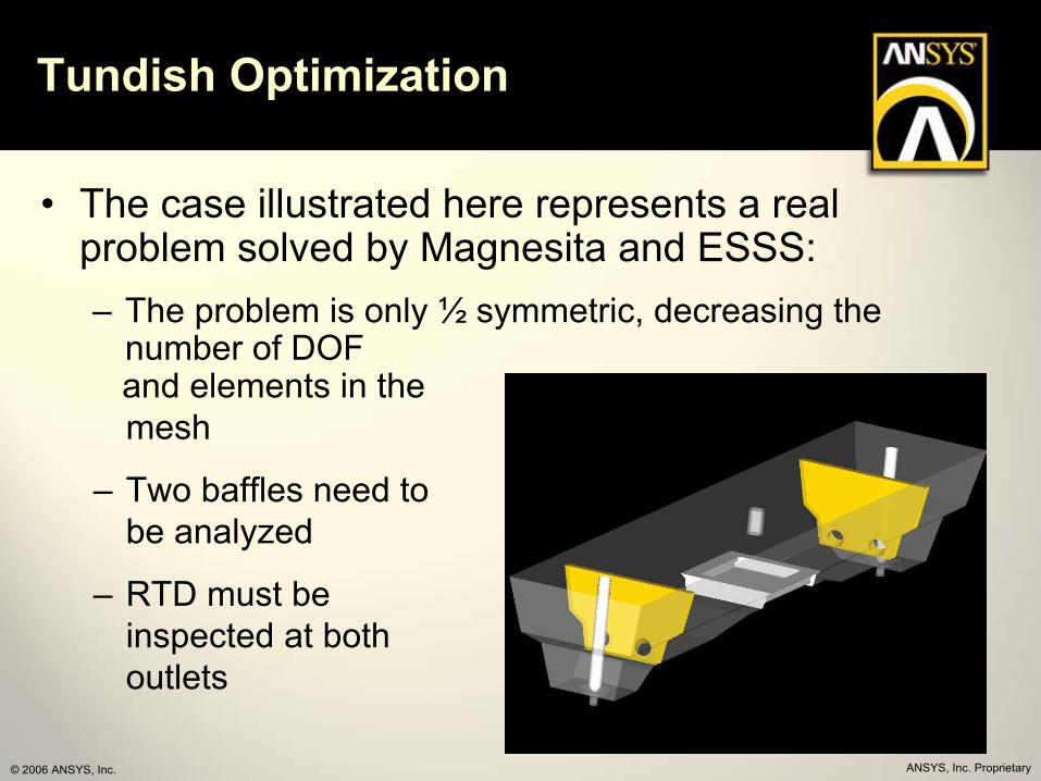
• The case illustrated here represents a real problem solved by Magnesita and ESSS:– The problem is only ½ symmetric, decreasing the
number of DOFand elements in the mesh
– Two baffles need to be analyzed
– RTD must be inspected at both outlets

ANSYS, Inc. Proprietary© 2006 ANSYS, Inc.
Tundish Optimization
• To simplify the problem, only two design parameters were considered:– HB: Baffle Height
– DB: Baffle Distance (from the outlet)
DB DB
HB HB

ANSYS, Inc. Proprietary© 2006 ANSYS, Inc.
Unstructured mesh with prisms (370k nodes)Transient: 2500 seconds, 1E-5 (approx. 26h)1E-5 (approx. 6h)
Tundish Optimization
• First step: Automatize the Evaluation process.
Geometry GenerationCATIA V5
Mesh generationANSYS ICEM CFD
Solve for FlowANSYS CFX
Solve TracerANSYS CFX
RTD AnalysesMS Excel
One evaluation: approx. 30h
modeFrontier• Process Integration• Optimization algorithms

ANSYS, Inc. Proprietary© 2006 ANSYS, Inc.
Tundish Optimization
• modeFrontier setup:
Input Parameters
Step 1: Geometry GenerationCatia Direct Node
Step 2: Mesh GenerationANSYS ICEM CFD
Step 3: Solve for FlowANSYS CFX
Step 4: Solve TracerANSYS CFX
Output Parameters(extracted from MS-Excel)
Step 5: DTR AnalysesMS-Excel Direct Node

ANSYS, Inc. Proprietary© 2006 ANSYS, Inc.
Tundish Optimization
• Since CFD analyses are computational demanding, a DOE and RSM (Response Surface) approach was adopted, saving computational time.
– DOE table with 25 designs:
• A Response Surface is created;
– The Optimization process runs in the RSM
• Virtual designs are founded;
– Virtual designs are evaluated;

ANSYS, Inc. Proprietary© 2006 ANSYS, Inc.
Tundish Optimization
• The DOE table was created uniformly along the Design Space:
HB
DB
Design Space
ANSYS, Inc. Proprietary© 2006 ANSYS, Inc.
Tundish Optimization
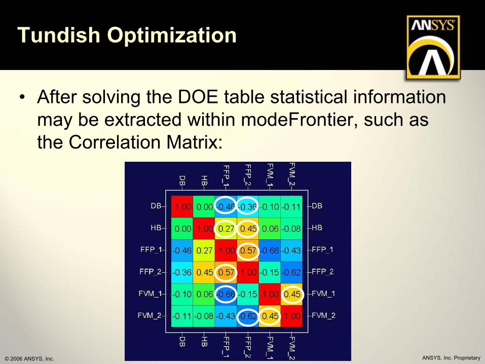
• After solving the DOE table statistical information may be extracted within modeFrontier, such as the Correlation Matrix:

ANSYS, Inc. Proprietary© 2006 ANSYS, Inc.
Tundish Optimization
• With the results of the DOE table a Response
Surface is created for each outlet and objective,
using Kriging’s algorithm:
– RSM for Plugged volume at Outlet 1
– RSM for Plugged volume at Outlet 2
– RSM for Dead volume at Outlet 1
– RSM for Dead volume at Outlet 2

ANSYS, Inc. Proprietary© 2006 ANSYS, Inc.
Tundish Optimization
• Plugged Volume – Outlet 1
ANSYS, Inc. Proprietary© 2006 ANSYS, Inc.
Tundish Optimization
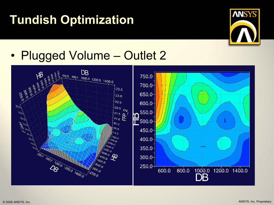
• Plugged Volume – Outlet 2

ANSYS, Inc. Proprietary© 2006 ANSYS, Inc.
Tundish Optimization
• Dead Volume – Outlet 1

ANSYS, Inc. Proprietary© 2006 ANSYS, Inc.
Tundish Optimization
• Dead Volume – Outlet 2
ANSYS, Inc. Proprietary© 2006 ANSYS, Inc.
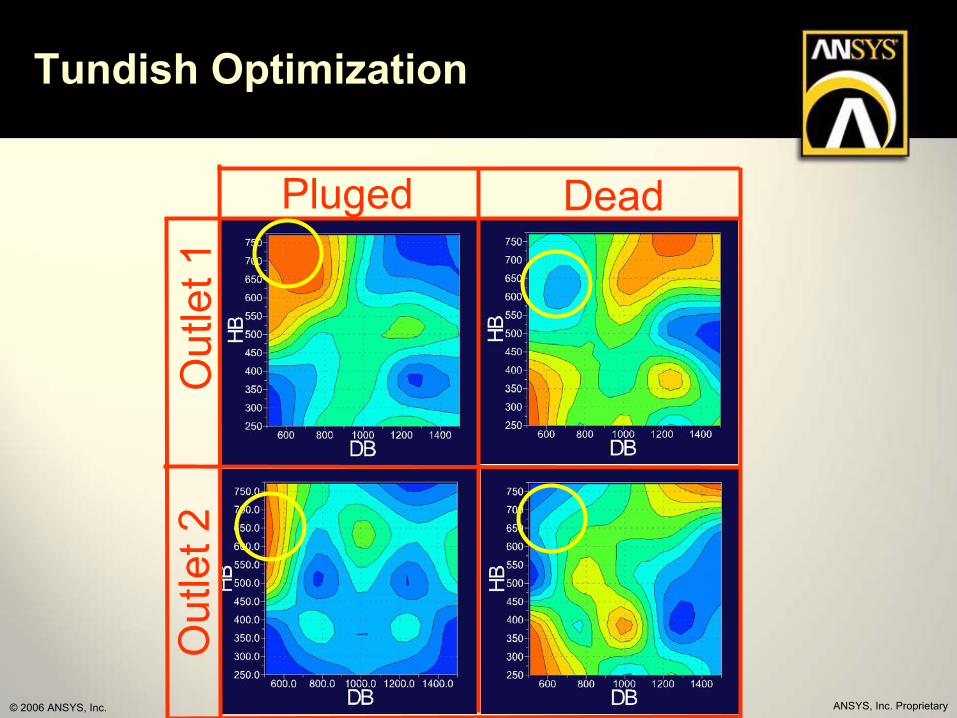
Tundish Optimization
Out
let1
Out
let2
Pluged Dead

ANSYS, Inc. Proprietary© 2006 ANSYS, Inc.
Tundish Optimization
• Response Surface inspection indicate that the best designs:– Are closer to the outlets
– Have higher baffles
• A Multi-Objective algorithm (MOGA II) is used to extract the best results from the Response Surface– Only two Objectives: Maximize Plugged volume at
both outlets (since Plugged and Dead volume are strongly correlated)

ANSYS, Inc. Proprietary© 2006 ANSYS, Inc.
Tundish Optimization
• Virtual Designs (the more red, the newer)
Plugged Volume 1
Plu
gged
Vol
ume
2

ANSYS, Inc. Proprietary© 2006 ANSYS, Inc.
Tundish Optimization
• Best Virtual Designs were located at the minimum distance from the outlets
• Three Virtual Designs were chosen to be validated
• The results were then compared to the initially suggested configuration (next Slide)

ANSYS, Inc. Proprietary© 2006 ANSYS, Inc.
Tundish Optimization
• Best Designs x Original Design
h1
h2
h3
h1
h2
h3
Original Design
Original Design
22
23
24
25
26
27
28
29
30
31
HB
(%)
Dead Volume Pluged Volume
h1
h2
h3
h1
h2
h3
Original Design
Original Design
22
23
24
25
26
27
28
29
30
31
HB
(%)
Dead Volume Pluged Volume
Outlet 1 Outlet 2

ANSYS, Inc. Proprietary© 2006 ANSYS, Inc.
Conclusions
• Baffles:
– Better Residence Time Distribution were found with higher baffles and closer to the outlet
– Increasing height will only improve results to a certain value
• Characteristic Volumes:
– Plugged and Dead volumes are strongly correlated.

ANSYS, Inc. Proprietary© 2006 ANSYS, Inc.
Future Studies
– Validate different methodologies for Residence Time Distribution calculation:
• Lagragean Models• Solving Residence Time as a Scalar
– Apply optimization techniques in other metallurgic components