tuning the surface properties of hydrogel at the nanoscale
TRANSCRIPT

Soft Matter
PAPER
Publ
ishe
d on
18
Aug
ust 2
014.
Dow
nloa
ded
by S
win
burn
e U
nive
rsity
of
Tec
hnol
ogy
on 2
5/02
/201
5 08
:28:
22.
View Article OnlineView Journal | View Issue
Tuning the surfa
aDepartment of Mechanical and Aerospace E
VIC, 3800, Australia. E-mail: jing.fu@monabDepartment of Chemical Engineering, M
AustraliacSchool of Applied Science, RMIT University
Cite this: Soft Matter, 2014, 10, 8448
Received 15th May 2014Accepted 18th August 2014
DOI: 10.1039/c4sm01061b
www.rsc.org/softmatter
8448 | Soft Matter, 2014, 10, 8448–845
ce properties of hydrogel at thenanoscale with focused ion irradiation
Y. Kim,a A. Y. Abuelfilat,a S. P. Hoo,b A. Al-Abboodi,b B. Liu,a Tuck Ng,a P. Chanc
and J. Fu*a
With the site-specificmachining capability of Focused Ion Beam (FIB) irradiation, we aim to tailor the surface
morphology and physical attributes of biocompatible hydrogel at the nano/micro scale particularly for
tissue engineering and other biomedical studies. Thin films of Gtn–HPA/CMC–Tyr hydrogels were
deposited on a gold-coated substrate and were subjected to irradiation with a kiloelectronvolt (keV)
gallium ion beam. The sputtering yield, surface morphology and mechanical property changes were
investigated using Scanning Electron Microscopy (SEM), Atomic Force Microscopy (AFM) and Monte
Carlo simulations. The sputtering yield of the hydrogel was found to be approximately 0.47 mm3 nC�1
compared with Monte-Carlo simulation results of 0.09 mm3 nC�1. Compared to the surface roughness of
the pristine hydrogel at approximately 2 nm, the average surface roughness significantly increased with
the increase of ion fluence with measurements extended to 20 nm at 100 pC mm�2. Highly packed
submicron porous patterns were also revealed with AFM, while significantly decreased pore sizes and
increased porosity were found with ion irradiation at oblique incidence. The Young's modulus of
irradiated hydrogel determined using AFM force spectroscopy was revealed to be dependent on ion
fluence. Compared to the original Young's modulus value of 20 MPa, irradiation elevated the value to
250 MPa and 350 MPa at 1 pC mm�2 and 100 pC mm�2, respectively. Cell culture studies confirmed that
the irradiated hydrogel samples were biocompatible, and the generated nanoscale patterns remained
stable under physiological conditions.
1. Introduction
Hydrogels are crosslinked networks composed of either naturalor synthetic polymers, and the hydrophilic properties ofhydrogels make them great materials for bioengineering.1,2 It iswell known that the shapes and physicochemical properties ofhydrogels have a strong inuence on cell growth and migration,and various approaches have been developed to tune theseproperties for improved cell growth and biocompatibility. Forexample, porosity and pore size could be altered throughadditional porogens, freeze-drying, photopatterning, foamgeneration, etc.,3–7 while the elastic modulus is a function ofcomponent concentrations.8,9 It has recently been suggestedthat, in addition to physical and chemical properties, topo-graphic properties at themicro and nanoscale play a critical rolein cellular interaction with its surrounding environment.10–13
For tissue engineering applications, it is now also advantageousto create nanoscale features on the surface with properties
ngineering, Monash University, Clayton,
sh.edu
onash University, Clayton, VIC, 3800,
, 3000, Australia
6
similar to those in the extracellular matrix in order to controlcellular behaviour and enhance cell growth, adhesion andproliferation.10,11,13–15
Previous studies on shape control of surface nanotopologywere typically based on so lithography16 or the intrinsic elasticproperty,16,17 predominantly on polydimethylsiloxane (PDMS);however, there are only limited reports on altering the surfacetopology of hydrogels at the micro and nanoscale, possibly dueto the technical difficulties involved in fabricating micro/nanoscale structures on so materials, or a limited knowledgeof the fundamental mechanisms involved. Recent reportsshowed that ion beam irradiation was capable of formingnanoscale wrinkle features on polymer surfaces.18–24 Typicallyequipped with a gallium ion (Ga+) or helium ion (He+) source, amodern Focused Ion Beam (FIB) instrument allows the accel-erated ions to perform site-specic milling with electrostaticlenses.25–27 In conjunction with scanning electron microscopy(SEM), micro- and nano-machining with resolution in nano-meteres down to single digits can be done while imaging andanalysing at the same time. FIB/SEM has been successfullyapplied for imaging applications such as three-dimensionalhydrogels,4 cell–material interfaces and even single cells.28–30
However, the capability of site-specic FIB milling is not fullyutilized for biomaterial applications.
This journal is © The Royal Society of Chemistry 2014

Paper Soft Matter
Publ
ishe
d on
18
Aug
ust 2
014.
Dow
nloa
ded
by S
win
burn
e U
nive
rsity
of
Tec
hnol
ogy
on 2
5/02
/201
5 08
:28:
22.
View Article Online
An example of a periodic pattern of micron size dots pre-sented in Fig. 1a was designed and preliminarily patterned on ahydrogel surface within minutes, without the use of chemicalsor sophisticated masks. This provided a quick method forfabricating nano/micro scale features on hydrogel, and the nalpattern was visible by optical microscopy with clearly denedgeometry (Fig. 1b). Under SEM, however, some morphologicalartefacts on the surface could be observed, and inconsistentgeometries such as the milling depth were also present due to alack of information (Fig. 1c). As such, the primary aim of thepresent research is to provide an in-depth investigation on thesurface topology and physical properties of hydrogel at thenano/micro scale by utilizing FIB to achieve designed patternsof high precision. The engineering issues including yield andangular effects were investigated through both Monte Carlosimulations and experimental studies. Other questions such assurface roughness and modulus of the hydrogel were measuredby Atomic Force Microscopy (AFM) prior to and aer ion irra-diation. Based on these results, patterns on hydrogel withtailored surface topology and physical attributes could beprecisely achieved by setting the beam parameters, e.g. accel-eration voltage, ion uence and incident angle. The compati-bility and stability of the patterned hydrogels were also tested incell culture to demonstrate the applicability of this patterningmethod for bioapplications.
2. Materials and methodsSample preparation
Carboxymethylcellulose–tyramine (CMC–Tyr) and gelatin–hydroxyphenylpropionic acid (Gtn–HPA) were synthesizedaccording to ref. 4. CMC–Tyr and Gtn–HPA conjugates wereeach dissolved in a phosphate buffer saline (PBS) solution at aconcentration of 5%. A hydrogel precursor solution wasprepared by mixing Gtn–HPA and CMC–Tyr in an 80 : 20 weightratio, respectively. This precursor went through a vigorousvortex for a few minutes. Horseradish peroxide (HRP) anddiluted H2O2 were then added to the precursor as cross-linkingreagents; each reagent was pre-diluted with PBS solution. A nalconcentration of 15.5 units per L of HRP and 49.8 � 10�6 M ofH2O2 was used in this research. This precursor was then
Fig. 1 Site-specific patterning on hydrogel with Focused Ion Beam(FIB) irradiation. (a) Designed pattern and (b) optical image of thecorresponding 1 mm diameter dots after patterning. (c) Low currentSEM image showing the detailed dots during ion milling.
This journal is © The Royal Society of Chemistry 2014
vigorously vortexed for a few minutes. The pH level of thehydrogel PBS solution before and aer cross-linking wasmeasured using a pHmeter (Thermo Fisher Scientic, Scoresby,VIC Australia). For the PBS solution, the pH level was measuredto be 7.51 and the pH level of the hydrogel before and aercross-linking was 7.35 and 7.41, respectively.
An aliquot of 100 mL of the precursor was deposited on a goldplated cover glass and any air bubbles were removed by gentlystirring with the tip of a micropipette. In order to achieve a thin,uniform layer of hydrogel, spin coating was performed in threestages. In the rst stage, spin coating was carried out at 500 rpmfor 10 seconds, followed by 3000 rpm for 40 seconds. Finally,another 500 rpm for 10 seconds of spin coating provided a thinuniform layer of mixture with a thickness of approximately 1mm. The precursor was then allowed to cross-link to form thehydrogel.
Focused Ion Beam (FIB) irradiation
FIB milling was performed on a FIB/SEM system (FEI HeliosNanoLab 600) equipped with a gallium liquid metal ion source(LMIS). Thin lms of hydrogel samples were rst transferred tothe system chamber until high vacuum status was reached. Theion current used in the experiment ranged from 0.92 pA to 0.97nA. Without additional notes, default overlapping and dwelltime were 0% and 3 ms, respectively. The ion uence of Ga+
ranging from 0.05 pC mm�2 to 600 pC mm�2 was regulated toirradiate a 10� 10 mm square region. The default incident anglewas kept at 0� (normal incidence), and to study the effect of theincident angle, the stage was tilted from 0� to 62�. SEM imageswere typically acquired with a secondary electron detector with a5 keV acceleration voltage and 86 pA current.
Atomic force microscopy (AFM)
Surface properties were examined using an AFM instrument(Dimension Icon, Bruker Corporation. Santa Barbara, CA, US) ina cleanroom environment. For measuring the surface topology,cantilevers with a 70 kHz resonance frequency and 0.4 N m�1
spring constant were used. By default, 20 � 20 mm regions werescanned to obtain reliable statistics. The sputtering yield of thehydrogel was calculated by examining the volume removed bythe ion beam irradiation and ion uence applied. Surfaceroughness and the characteristics of regular patterns werecalculated using the soware package NanoScope Analysis 1.4(Bruker Corporation. Santa Barbara, CA, US). For the forcemeasurements and modulus calculations, a cantilever with a0.06 N m�1 spring constant was used to accommodate the lowmodulus of the hydrogel sample with a JPK NanoWizard2 AFM(JPK Instruments AG, Berlin, Germany) under ambient condi-tions. Calibration of the cantilever was conducted prior to theforce mapping using a mica sheet, measuring the sensitivityand spring constant of the cantilever. Force mapping of thesample of 5 � 5 mm regions were done at 16 � 16 resolution.Analysis was carried on using JPKSPM Data Processing soware(JPK Instruments AG, Berlin, Germany) which allows batchprocessing.
Soft Matter, 2014, 10, 8448–8456 | 8449
Soft Matter Paper
Publ
ishe
d on
18
Aug
ust 2
014.
Dow
nloa
ded
by S
win
burn
e U
nive
rsity
of
Tec
hnol
ogy
on 2
5/02
/201
5 08
:28:
22.
View Article Online
SRIM Monte-Carlo simulation
A Monte-Carlo simulation of the sputtering process of hydrogelwas performed with the soware package SRIM (The Stoppingand Range of Ions in Matter) version 2013.31 The hydrogel wasset up as a new compound consisting of carbon, hydrogen andoxygen with an atomic stoichiometry of 8 : 8 : 1, respectively.The density of the hydrogel was obtained by measuring the bulkweight and volume, and the average value 1.655 g cm�3
obtained was input for all of the simulations. At least 5000 ionswere simulated in each run, and parameters including the angleof incident and ion energy were varied based on the parametersused in the experiments.
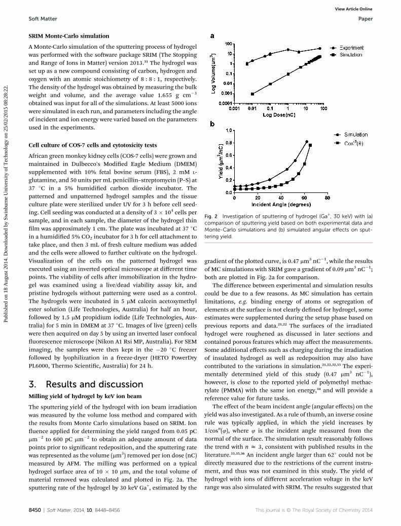
Fig. 2 Investigation of sputtering of hydrogel (Ga+, 30 keV) with (a)comparison of sputtering yield based on both experimental data andMonte-Carlo simulations and (b) simulated angular effects on sput-tering yield.
Cell culture of COS-7 cells and cytotoxicity tests
African green monkey kidney cells (COS-7 cells) were grown andmaintained in Dulbecco's Modied Eagle Medium (DMEM)supplemented with 10% fetal bovine serum (FBS), 2 mM L-glutamine, and 50 units per mL penicillin–streptomycin (P–S) at37 �C in a 5% humidied carbon dioxide incubator. Thepatterned and unpatterned hydrogel samples and the tissueculture plate were sterilized under UV for 3 h before cell seed-ing. Cell seeding was conducted at a density of 3 � 104 cells persample, and in each sample, the diameter of the hydrogel thinlm was approximately 1 cm. The plate was incubated at 37 �Cin a humidied 5% CO2 incubator for 3 h for cell attachment totake place, and then 3 mL of fresh culture medium was addedand the cells were allowed to further cultivate on the hydrogel.Visualization of the cells on the patterned hydrogel wasexecuted using an inverted optical microscope at different timepoints. The viability of cells aer immobilization in the hydro-gel was examined using a live/dead viability assay kit, andpristine hydrogels without patterning were used as a control.The hydrogels were incubated in 5 mM calcein acetoxymethylester solution (Life Technologies, Australia) for half an hour,followed by 1.5 mM propidium iodide (Life Technologies, Aus-tralia) for 5 min in DMEM at 37 �C. Images of live (green) cellswere then acquired on day 5 by using an inverted laser confocaluorescence microscope (Nikon A1 Rsi MP, Australia). For SEMimaging, the samples were then kept in the �20 �C freezerfollowed by lyophilization in a freeze-dryer (HETO PowerDryPL6000, Thermo Scientic, Australia) for 24 h.
3. Results and discussionMilling yield of hydrogel by keV ion beam
The sputtering yield of the hydrogel with ion beam irradiationwas measured by the volume loss method and compared withthe results from Monte Carlo simulations based on SRIM. Ionuence applied for determining the yield ranged from 0.05 pCmm�2 to 600 pC mm�2 to obtain an adequate amount of datapoints prior to signicant redeposition, and the sputtering ratewas represented as the volume (mm3) removed per ion dose (nC)measured by AFM. The milling was performed on a typicalhydrogel surface area of 10 � 10 mm, and the total volume ofmaterial removed was calculated and plotted in Fig. 2a. Thesputtering rate of the hydrogel by 30 keV Ga+, estimated by the
8450 | Soft Matter, 2014, 10, 8448–8456
gradient of the plotted curve, is 0.47 mm3 nC�1, while the resultsof MC simulations with SRIM gave a gradient of 0.09 mm3 nC�1;both are plotted in Fig. 2a for comparison.
The difference between experimental and simulation resultscould be due to a few reasons. As MC simulation has certainlimitations, e.g. binding energy of atoms or segregation ofelements at the surface is not clearly dened for hydrogel, someestimates were supplemented during the setup phase based onprevious reports and data.21,22 The surfaces of the irradiatedhydrogel were roughened as discussed in later sections andcontained porous features which may affect the measurements.Some additional effects such as charging during the irradiationof insulated hydrogel as well as redeposition may also havecontributed to the variations in simulation.21,22,32,33 The experi-mentally determined yield of this study (0.47 mm3 nC�1),however, is close to the reported yield of polymethyl methac-rylate (PMMA) with the same ion energy,34 and will provide areference value for future tasks.
The effect of the beam incident angle (angular effects) on theyield was also investigated. As a rule of thumb, an inverse cosinerule was typically applied, in which the yield increases by1/cosn(4), where 4 is the incident angle measured from thenormal of the surface. The simulation result reasonably followsthe trend with n z 3, consistent with published results in theliterature.22,35,36 An incident angle larger than 62� could not bedirectly measured due to the restrictions of the current instru-ment, and thus was not examined in this study. The yield ofhydrogel with ions of different acceleration voltage in the keVrange was also simulated with SRIM. The results suggested that
This journal is © The Royal Society of Chemistry 2014

Paper Soft Matter
Publ
ishe
d on
18
Aug
ust 2
014.
Dow
nloa
ded
by S
win
burn
e U
nive
rsity
of
Tec
hnol
ogy
on 2
5/02
/201
5 08
:28:
22.
View Article Online
the sputtering yield gradually increased and reached its peakpoint close to 30 keV. With the acceleration voltage approaching60 keV, the yield of hydrogel started to decrease. This result alsoagrees with the trends found in previous reports for variousmaterials.35,37
Surface morphology of irradiated hydrogel
The surface roughness of the hydrogel surface prior to and aerirradiation was investigated with AFM, with ion uence rangingfrom 0.05 pC mm�2 to 100 pC mm�2. Two examples of ion u-ence at 0.1 pC mm�2 and 100 pC mm�2 were presented in Fig. 3aand b, respectively. For each obtained image, measurementswere performed at multiple locations in both pristine andirradiated regions. At an ion uence of 0.1 pC mm�2, nosignicant morphological change was observed, and even theoriginal swelling islands on the pristine hydrogel remainedunchanged aer the irradiation (Fig. 3a). In Fig. 3b, a dramaticporous pattern was introduced on the bottom of the milledcavity aer signicantly extended irradiation (100 pC mm�2)compared to the smoother pristine surface. Detailed measure-ments of the surface roughness are presented in Fig. 3cincluding side-by-side comparisons with regard to ion irradia-tion. It is evident that surface roughness was at least doubledaer irradiation; however, the average values remained below10 nm at initial ion uences. A surge occurred at an ion uenceof 1 pC mm�2, and the average surface roughness was elevated to
Fig. 3 AFM images (top view) of surface morphology after ion milling(Ga+, 30 keV) with an ion fluence of (a) 0.1 pC mm�2 and (b) 100 pCmm�2. (c) The corresponding numerical values of surface roughness ofpristine hydrogel and after ion irradiation with increasing ion fluence(scale bar: 5 mm).
This journal is © The Royal Society of Chemistry 2014
20 nm at an ion uence of 100 pC mm�2. This result suggeststhat nanoscale roughening occurs aer initial radiation,while aer achieving a certain threshold, an erosion-typemorphology becomes the dominant appearance on the hydrogelsurface.
Previous reports showed directional patterns on poly-mers,18,35,38–41 such as oriented ripples, wrinkles, etc., which aremainly induced by the interplay of sputtering erosion andsurface relaxation mechanisms, e.g. surface expansion which isperpendicular to the direction of the ion beam.39 In addition tosurface roughness, these unique patterns and the distributionsare also interesting phenomena and were the subjects ofinvestigations with different ion irradiation parameters in thisstudy. Fig. 4a and b present selected AFM images aer FIBirradiation at 0� incident angles (normal) on hydrogel. Theincident angle was raised to 50� and 60�, with the results pre-sented in Fig. 4c and d, respectively. A 2D prole of the AFMmeasurements is presented in Fig. 4g to demonstrate the typicalcross-section. Overall, porous structures were observed acrossall of the irradiated samples, with average diameters in theorder of several hundreds of nanometers. Contrary to previousreports, no signicant orientation was observed in the patternsgenerated on the hydrogel surface in this study regardless ofthe ion uence or incident angle. This may be due to thefact that synthetic hydrogel possesses more heterogeneousstructures compared to single-component polymers, and thesputtering yield was varied across the surface to promote theformation of porous structures. Although it is feasible forhydrogel to have a controlled microscale porous morphology forscaffolding,4 the proposed ion irradiation approach providesunique controllable submicron pores which are challenging forother approaches.
The patterns measured by AFM were further analysed toobtain details of the submicron pores. By converting the orig-inal AFM data to binary images as shown in Fig. 4e and f,porosity, as dened by the percentage of void to overall area,could then be quantied. The measured pore size and porosityat varied ion uence and incident angles were summarized inFig. 5a–d. The results showed that the size of the porouspatterns was not signicantly changed with the increase of ionuence, and the average pore size and porosity are approxi-mately 600 nm and 0.45 respectively (Fig. 5a and c). This alsosuggests that pore formation requires limited ion uence evenat 1 pC mm�2, and then with the increase in ion uence, thehydrogel surface underwent uniform erosion with similarporous structures. In comparison, results based on a higherincident angle (50 to 60 degree) showed similar porous struc-tures (Fig. 4c and d) but with signicantly smaller pore size andhigher porosity (Fig. 5b and d). It is common practice for ionsputtering at oblique incidence to introduce differentmorphology for inorganic materials.42 For the current study, theaverage implantation depth of the incident gallium ion wasreduced at higher incident angles, and the overall transferredkinetic energy is in closer proximity to the top surface layer. Thisallowed sputtering at the top layer to be more effectivecompared to other dynamic surface mechanisms, and thusresulted in pores of higher density.
Soft Matter, 2014, 10, 8448–8456 | 8451

Fig. 4 3D AFM images of the porous patterns after ion irradiation (Ga+, 30 keV) with ion fluence from (a) 1 pC mm�2, 0� incident angle to (b) 100pC mm�2, 0� incident angle. Porosity increases with the increase of incident angle from (c) 100 pC mm�2, 52� incident angle to (d) 100 pC mm�2,62� incident angle. The corresponding converted binary images for porosity measurements after irradiation at incident angle (e) 0� and (f) 62�. (g)A cross-section profile of hydrogel after irradiation based on AFM.
Soft Matter Paper
Publ
ishe
d on
18
Aug
ust 2
014.
Dow
nloa
ded
by S
win
burn
e U
nive
rsity
of
Tec
hnol
ogy
on 2
5/02
/201
5 08
:28:
22.
View Article Online
Modulus of irradiated hydrogel
Mechanical elasticity has been widely accepted as a control-lable factor for cell growth and differentiation.9,43 Though it isfeasible to tune the elasticity of polymers including hydrogelin bulk forms by varying the concentrations,8 controlled elas-ticity modication, particularly at the submicron scale, hasnever been established. Previous studies39,44 showed a signi-cantly higher modulus of PDMS aer keV ion irradiation, andin the present study, we also aim to investigate the modulusthrough FIB irradiation in situ. The results measured by AFMforce spectroscopy are presented in Fig. 6 with ion uencefrom 1 pC mm�2 to 100 pC mm�2. Compared to pristinehydrogel, the average modulus was signicantly elevated withthe increase in ion uence, from less than 20 MPa for pristinehydrogel to 250 MPa at an ion uence of 1 pC mm�2 and 350MPa at an ion uence of 100 pC mm�2. All the AFM modulusmeasurements were performed under ambient conditions,
8452 | Soft Matter, 2014, 10, 8448–8456
and although preferred, measuring the modulus of hydrogel inliquid medium remains a challenge, as it is well known thathydrogel response in water is varied. Also, in order to accom-modate the estimated modulus range of hydrated hydrogel,so cantilevers with a spring constant of 0.03 N m�1 wereinitially used in a few attempts, and cantilevers were likelybroken at the air–liquid interface, possibly due to surfacetension at the air–liquid interface. The ttings based on a fewsuccessful measurements suggested that the modulus ofhydrated hydrogel is in the range of 100 kPa to 1 MPa,consistent with the reported hydration induced effects.45,46 Theincreased water content in the hydrogel may have resulted in alarger probe–surface contact area, and the actual hydration–modulus relationship aer ion irradiation will be an inter-esting topic for future study.
It is interesting to note that the site-specic modulus tuningof post-crosslinking hydrogel accomplished in this study has
This journal is © The Royal Society of Chemistry 2014

Fig. 5 Numerical values of pore size on hydrogel after ion irradiation (Ga+, 30 keV) measured by AFM with (a) ion fluences ranging from1 pC mm�2 to 600 pC mm�2 and (b) incident angles ranging from 0� to 62�. Data for porosity after irradiation at varied ion fluences and incidentangles are presented in (c) and (d).
Paper Soft Matter
Publ
ishe
d on
18
Aug
ust 2
014.
Dow
nloa
ded
by S
win
burn
e U
nive
rsity
of
Tec
hnol
ogy
on 2
5/02
/201
5 08
:28:
22.
View Article Online
not been feasible with other existing approaches. Althoughfocused electron beam irradiation was deployed for localizedcrosslinking of hydrogel,47,48 the fabricated features wereattached to a substrate such as silicon and was not applicablefor tissue engineering. A swelling effect of the electronpatterned hydrogel was reported, but so far no details onmodulus have been provided. In the current study, nuclear
Fig. 6 Young's modulus of hydrogel prior to and after the irradiation (Ga+
represent the fitted normal distributions of the fitted histograms.
This journal is © The Royal Society of Chemistry 2014
stopping of the gallium ions is expected to be dominant inconjunction with the MC simulation results, and that causessubstantial nuclear displacements and scission of bonds in thetarget hydrogel. A transition from one-dimensional chains intoa three-dimensional matrix may provide an explanation for theelevated Young's modulus,49,50 although a more conclusivestudy is needed in the future.
, 30 keV) with ion fluence from 1 pC mm�2 to 100 pC mm�2. Solid curves
Soft Matter, 2014, 10, 8448–8456 | 8453

Soft Matter Paper
Publ
ishe
d on
18
Aug
ust 2
014.
Dow
nloa
ded
by S
win
burn
e U
nive
rsity
of
Tec
hnol
ogy
on 2
5/02
/201
5 08
:28:
22.
View Article Online
Results of cell culture on patterned hydrogel
To assess the stability of the generated patterns, ion irradiatedsamples were kept in a physiological environment for 48 h, i.e.with the same culture medium and temperature but withoutseeding cells. Aer dehydration, the samples were nallyinvestigated with both optical and SEM imaging (Fig. 7a and b),and the original FIB milled patterns were clearly presentwithout noticeable changes. This suggests that the FIB milledpatterns are stable in a cell culture environment, at least prior tothe controlled dissolution of hydrogel. Although increased
Fig. 7 Without cell seeding: (a) optical image of ion beam inducedpatterns, compared with (b) the same patterns kept in a physiologicalenvironment for 48 h (SEM image). Optical images of cells on non-irradiated hydrogels (c) at 0 h, and (d) at 44 h after cell seeding. Opticalimages of cells on irradiated hydrogel (e) at 0 h, and (f) at 44 h after cellseeding. Confocal images of cell morphology on (g) the controlhydrogel sample, and (h) the patterned hydrogel. (Scale bar: 10 mm in aand b, 50 mm in c–f.)
8454 | Soft Matter, 2014, 10, 8448–8456
roughness aer ion irradiation resulted in a larger contactsurface area, hardening of the top layer as shown by theincreased modulus may provide an additional barrier againstphysical and chemical modications of the patterns.
To demonstrate the biocompatibility of FIB patterning onhydrogel, cell culture experiments were performed on the irra-diated samples. Optical images recorded right aer seeding andat 44 h aer seeding are presented in Fig. 7c–f. For both irra-diated and non-irradiated samples, the COS-7 cells reachedconuence, and displayed typical spread out morphology. Thesame morphology was observed in the 10 mm ion irradiatedsquare regions (Fig. 7d) compared to the cells grown on theirradiated hydrogel surface. In addition, confocal microscopywas performed to provide higher magnication investigations,with results presented in Fig. 7g and h. It is clear that, for bothirradiated and non-irradiated samples, COS-7 cells were rmlyadhered to hydrogel, a scenario consistent with this type ofhydrogel in the literature.4 For the cells grown on the rectanglepatterned regions as shown in Fig. 7h, nomeasurable differencein morphology was found. The viability of these cells wasconrmed by the consistent green uorescent color, without thepresence of any dead cells. These results conrmed that galliumion beam irradiation has negligible effects on cell growth,although gallium is generally considered as toxic.51,52 FromSRIM results, the majority of the incident gallium will eventu-ally be implanted into the target hydrogel, and the free galliumions, which are a possible source of the toxicity, are expected tobe minimal on the hydrogel surface. It can also be inferred thatpatterns generated by other commercially available FIB sourcesbased on noble gases such as helium, neon, etc. will likely bebiocompatible, although additional studies to conrm it wouldbe preferable. The results of both experiments presented aboveprove the stability and compatibility of these nano/microscale patterns on hydrogel, and pave the way towards variousbioapplications.
4. Conclusion
In conclusion, Focused Ion Beammilling was performed on thethin lms of hydrogel to tune various surface propertiesincluding surface morphology and modulus, characterized byelectron microscopy and AFM. The sputtering yield of hydrogelby a keV gallium ion beam was examined experimentally andcompared to results obtained from Monte-Carlo simulations. Itwas revealed that the surface roughness was doubled aer lowdose irradiation, and a signicant increase in the Young'smodulus was also conrmed. During irradiation, uniquenanoscale porous features in regular formation were alsoobserved, and the pore parameters were found to be dependenton ion incident angles. Cell culture experiments conrmed thebiocompatibility and stability of the patterns generated basedon FIB with gallium sources. Given the in situ high precisioncapability and sufficient yield compared to laser and electronbeam based approaches, we expect that the proposed approachwill provide tunable submicron features on hydrogel whichare unique for future research in tissue engineering andbiosensing.
This journal is © The Royal Society of Chemistry 2014

Paper Soft Matter
Publ
ishe
d on
18
Aug
ust 2
014.
Dow
nloa
ded
by S
win
burn
e U
nive
rsity
of
Tec
hnol
ogy
on 2
5/02
/201
5 08
:28:
22.
View Article Online
Acknowledgements
Funding for this research was partly provided through AustraliaResearch Council Discovery Project Grant (DP120102570 andDP120100583) and Seed Fund of Monash Engineering. Thiswork was performed in part at the Melbourne Centre forNanofabrication (MCN) in the Victorian Node of the AustralianNational Fabrication Facility (ANFF). The author would like tothank the staff from MCN for various support and training.
References
1 J. Kopecek, Biomaterials, 2007, 28, 5185–5192.2 A. C. Jen, M. C. Wake and A. G. Mikos, Biotechnol. Bioeng.,1996, 50, 357–364.
3 Q. Liu, E. L. Hedberg, Z. Liu, R. Bahulekar, R. K. Meszlenyiand A. G. Mikos, Biomaterials, 2000, 21, 2163–2169.
4 A. Al-Abboodi, J. Fu, P. M. Doran, T. T. Tan and P. P. Chan,Adv. Healthcare Mater., 2013, 3, 725–736.
5 S. J. Bryant, J. L. Cuy, K. D. Hauch and B. D. Ratner,Biomaterials, 2007, 28, 2978–2986.
6 S. P. Hoo, Q. L. Loh, Z. Yue, J. Fu, T. T. Y. Tan, C. Choong andP. P. Y. Chan, J. Mater. Chem. B, 2013, 1, 3107–3117.
7 J.-y. Lin, W.-j. Lin, W.-h. Hong, W.-c. Hung, S. H. Nowotarski,S. M. Gouveia, I. Cristo and K.-h. Lin, So Matter, 2011, 7,10010–10016.
8 J. R. Tse and A. J. Engler, Curr Protoc Cell Biol., 2010,10.16.11–10.16.16.
9 A. J. Engler, S. Sen, H. L. Sweeney and D. E. Discher, Cell,2006, 126, 677–689.
10 F. Boccafoschi, M. Rasponi, C. Mosca, E. Bocchi andS. Vesentini, Adv. Mater., 2012, 409, 109–110.
11 Z. Pan, C. Yan, R. Peng, Y. Zhao, Y. He and J. Ding,Biomaterials, 2012, 33, 1730–1735.
12 M. M. Stevens and J. H. George, Science, 2005, 310, 1135–1138.
13 W. Chen, L. G. Villa-Diaz, Y. Sun, S. Weng, J. K. Kim,R. H. W. Lam, L. Han, R. Fan, P. H. Krebsbach and J. Fu,ACS Nano, 2012, 6, 4094–4103.
14 L. Csaderova, E. Martines, K. Seunarine, N. Gadegaard,C. D. W. Wilkinson and M. O. Riehle, Small, 2010, 6, 2755–2761.
15 E. K. F. Yim, E. M. Darling, K. Kulangara, F. Guilak andK. W. Leong, Biomaterials, 2010, 31, 1299–1306.
16 P. Kim, W. E. Adorno-Martinez, M. Khan and J. Aizenberg,Nat. Protoc., 2012, 7, 311–327.
17 Y. Zhang, E. A. Matsumoto, A. Peter, P.-C. Lin, R. D. Kamienand S. Yang, Nano Lett., 2008, 8, 1192–1196.
18 M.-W. Moon, S. H. Lee, J.-Y. Sun, K. H. Oh, A. Vaziri andJ. W. Hutchinson, Scr. Mater., 2007, 57, 747–750.
19 T. Kaito, in Introduction to Focused Ion Beams, ed. L.Giannuzzi and F. Stevie, Springer, US, 2005, ch. 4, pp. 73–86.
20 K. M. Lee, A. Neogi, J. M. Perez and T. Y. Choi,Nanotechnology, 2010, 21, 205303.
21 J. J. L. Mulders, D. A. M. de Winter andW. J. H. C. P. Duinkerken, Microelectron. Eng., 2007, 84,1540–1543.
This journal is © The Royal Society of Chemistry 2014
22 H. Ostadi, K. Jiang and P. D. Prewett, Microelectron. Eng.,2009, 86, 1021–1024.
23 M. Serantoni, A. S. Sarac and D. Sutton, Surf. Coat. Technol.,2005, 194, 36–41.
24 F. A. Stevie, L. A. Giannuzzi and B. I. Prenitzer, inIntroduction to Focused Ion Beams, ed. L. Giannuzzi and F.Stevie, Springer, US, 2005, ch. 1, pp. 1–12.
25 A. Gaston, A. Z. Khokhar, L. Bilbao, V. Saez-Martınez,A. Corres, I. Obieta and N. Gadegaard, Microelectron. Eng.,2010, 87, 1057–1061.
26 A. Al-Abboodi, J. Fu, P. M. Doran and P. P. Y. Chan,Biotechnol. Bioeng., 2013, 110, 318–326.
27 F. Boccafoschi, M. Rasponi, C. Mosca, E. Bocchi andS. Vesntini, Adv. Mater. Res., 2012, 409, 105–110.
28 G. E. Murphy, K. Narayan, B. C. Lowekamp, L. M. Hartnell,J. A. Heymann, J. Fu and S. Subramaniam, J. Struct. Biol.,2011, 176, 268–278.
29 J. A. Heymann, D. Shi, S. Kim, D. Bliss, J. L. Milne andS. Subramaniam, J. Struct. Biol., 2009, 166, 1–7.
30 B. Liu, H. H. Yu, T. W. Ng, D. L. Paterson, T. Velkov, J. Li andJ. Fu, Microsc. Microanal., 2014, 20, 537–547.
31 SRIM – The Stopping and Range of Ions in Matter, 2014,http://www.srim.org.
32 P. J. Cumpson, J. F. Portoles, A. J. Barlow, N. Sano andM. Birch, Surf. Interface Anal., 2013, 45, 1859–1868.
33 R. D. Kolasinski, J. E. Polk, D. Goebel and L. K. Johnson, J.Vac. Sci. Technol., A, 2007, 25, 236.
34 FEI Company, Operation manual of dual beam system,2014.
35 J. Munoz-Garcıa, L. Vazquez, R. Cuerno, J. Sanchez-Garcıa,M. Castro and R. Gago, in Toward FunctionalNanomaterials, ed. Z. M. Wang, Springer, US, 2009, ch. 10,vol. 5, pp. 323–398.
36 J. Fu, S. B. Joshi and J. M. Catchmark, J. Micromech.Microeng., 2008, 18, 095010.
37 J. Fu, S. B. Joshi and J. M. Catchmark, J. Vac. Sci. Technol., A,2008, 26, 422–429.
38 M. Guvendiren and J. A. Burdick, Biomaterials, 2010, 31,6511–6518.
39 M.-W. Moon, S. H. Lee, J.-Y. Sun, K. H. Oh, A. Vaziri andJ. W. Hutchinson, Proc. Natl. Acad. Sci. U. S. A., 2007, 104,1130–1133.
40 C. O. Yang, E. K. Her, K. H. Oh and T. J. Kang, J. Korean Phys.Soc., 2012, 61, 297–300.
41 J. Yin and C. Lu, So Matter, 2012, 8, 6528.42 B. Ziberi, F. Frost, B. Rauschenbach and T. Hoche, Appl.
Phys. Lett., 2005, 87, 033113.43 D. E. Discher, P. Janmey and Y.-l. Wang, Science, 2005, 310,
1139–1143.44 C. E. Foerster, I. T. S. Garcia, F. C. Zawislak, F. C. Serbena,
C. M. Lepienski, W. H. Schreiner and M. Abbate, Thin SolidFilms, 2002, 411, 256–261.
45 R. A. Frazier, M. C. Davies, G. Matthijs, C. J. Roberts,E. Schacht, S. J. B. Tendler and P. M. Williams, Langmuir,1997, 13, 4795–4798.
46 M. Radmacher, M. Fritz and P. K. Hansma, Biophys. J., 1995,69, 264–270.
Soft Matter, 2014, 10, 8448–8456 | 8455

Soft Matter Paper
Publ
ishe
d on
18
Aug
ust 2
014.
Dow
nloa
ded
by S
win
burn
e U
nive
rsity
of
Tec
hnol
ogy
on 2
5/02
/201
5 08
:28:
22.
View Article Online
47 P. Krsko, S. Sukhishvili, M. Manseld, R. Clancy andM. Libera, Langmuir, 2003, 19, 5618–5625.
48 Y. Hong, P. Krsko and M. Libera, Langmuir, 2004, 20, 11123–11126.
49 J. Jagielski, A. Turos, D. Bielinski, A. M. Abdul-Kader andA. Piatkowska, Nucl. Instrum. Methods Phys. Res., Sect. B,2007, 261, 690–693.
8456 | Soft Matter, 2014, 10, 8448–8456
50 R. L. Clough, Nucl. Instrum. Methods Phys. Res., Sect. B, 2001,185, 8–33.
51 M. M. Hart and R. H. Adamson, Proc. Natl. Acad. Sci. U. S. A.,1971, 68, 1623–1626.
52 FEI Company, Material Safety Data Sheet Gallium.
This journal is © The Royal Society of Chemistry 2014