tunnel cooling programme (tcp) systems engineering · tunnel cooling programme (tcp) systems...
TRANSCRIPT

UNDERGROUND Engineering Directorate
Tunnel Cooling Programme (TCP)Systems Engineering
Mark Gilbey &
Jonathan Harding
UNDERGROUND Engineering Directorate
Purpose
• Explain the complexity of the problem
• Explain how we are using Systems Engineeringin the Tunnel Cooling Programme to manage thenetwork wide, long term cooling challenge
• Show examples of the proposed solutions

UNDERGROUND Engineering Directorate
Problem• The TCP was set up in recognition of LU’s desire to
improve the thermal conditions for the travelling public.
• Whilst thermal conditions on some portions of LU’sunderground system are already reported to beuncomfortable, conditions could become significantlyworse as a consequence of the proposedimprovements in journey time capability required aspart of the PPP contracts.
• The TCP GOAL is to improve passenger comfort andsafety by maintaining 29°C station temperatures intime for the line upgrade programme between 2012and 2019.

UNDERGROUND Engineering Directorate
Current Tunnel Temperatures

UNDERGROUND Engineering Directorate
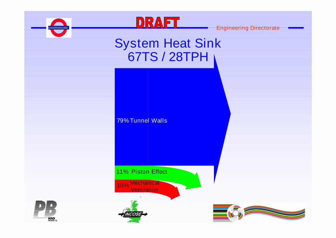
Energy Sources
UNDERGROUND Engineering Directorate
79%
11%
10%
Tunnel Walls
Piston Effect
Mechanical
Ventilation
System Heat Sink67TS / 28TPH
UNDERGROUND Engineering Directorate
CAR AIR VOLUMETUNNEL AIR VOLUME
CAR WALLS
CARINTAKE
AIR
CARRELIEF AIR
PASSENGERS
INTERNALAUXILIARIES
EXTERNALAUXILIARIES
TUNNEL WALLS
RESISTORGRIDS
INTAKE AIRFROM
UPSTREAMSEGMENT
CAR HEAT BALANCE
TUNNEL HEAT BALANCE
AC SYSTEMAC
CONDENSER
skin
fat
muscle
core
radiant flux
HVAC inlet
Person
Train
Mesh
Cross Section
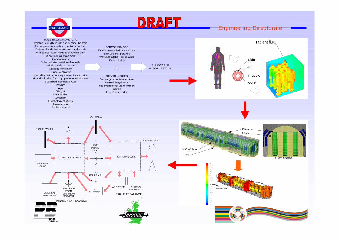
POSSIBLE PARAMETERSRelative humidity inside and outside the trainAir temperature inside and outside the trainCarbon dioxide inside and outside the trainWall temperature inside and outside train
In-carriage air movementCondensation
Solar radiation outside of tunnelsWind outside of tunnels
Carriage ventilationTunnel ventilation
Heat dissipation from equipment inside trainsHeat dissipation from equipment outside trains
Sustained electrical powerPosture
AgeWeight
Train loadingCrowding
Psychological stressPre-exposure
Acclimatisation
STRAIN INDICESPassenger core temperature
Rate of dehydrationMaximum exposure to carbon
dioxideHeat Stress Index
STRESS INDICESEnvironmental indices such as:
Effective TemperatureWet Bulb Globe Temperature
Oxford Index
ALLOWABLEEXPOSURE TIMEOR

UNDERGROUND Engineering Directorate
How the Tunnel Cooling Programme is usingSystems Engineering

UNDERGROUND Engineering Directorate
TCP Document hierarchy
SteeringGroup brief
Technical Work scope packages
Design and BuildPackages
Detailed design
Project ObjectiveDefinition
FunctionalSpecification
Operational RailwaySystem Specification
Principal RequirementsSpecification
Line Application Specification
UNDERGROUND Engineering Directorate
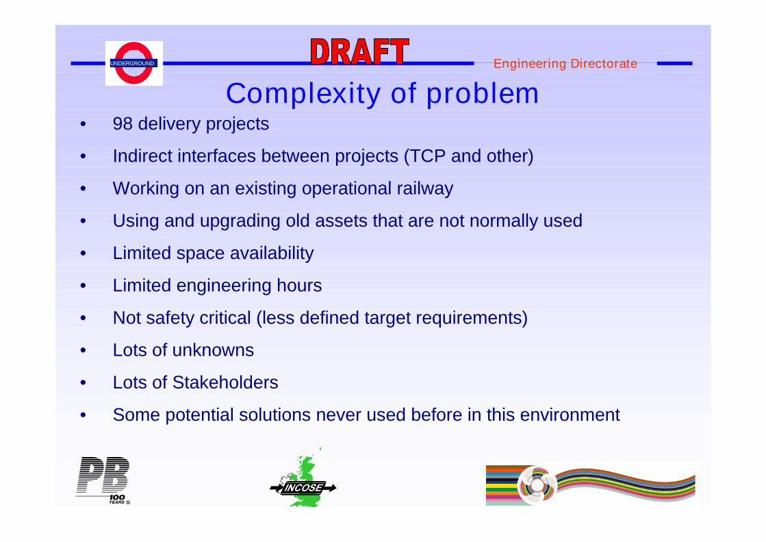
Complexity of problem• 98 delivery projects
• Indirect interfaces between projects (TCP and other)
• Working on an existing operational railway
• Using and upgrading old assets that are not normally used
• Limited space availability
• Limited engineering hours
• Not safety critical (less defined target requirements)
• Lots of unknowns
• Lots of Stakeholders
• Some potential solutions never used before in this environment

UNDERGROUND Engineering Directorate
Solution breakdown
UNDERGROUND Engineering Directorate
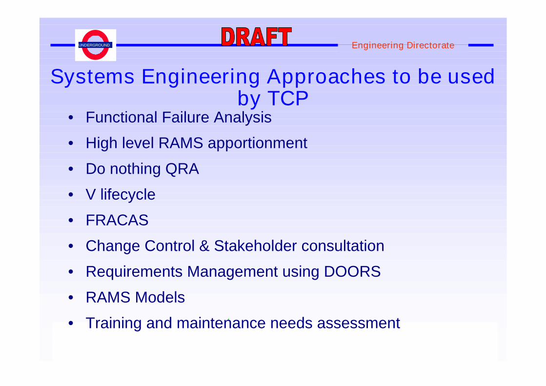
Systems Engineering Approaches to be usedby TCP
• Functional Failure Analysis
• High level RAMS apportionment
• Do nothing QRA
• V lifecycle
• FRACAS
• Change Control & Stakeholder consultation
• Requirements Management using DOORS
• RAMS Models
• Training and maintenance needs assessment

UNDERGROUND Engineering Directorate
Failure mode <3hr >3hrs
100% failure single station low tangible
50% failure multiple stations low tangible
100% failure multiple stations tangible high
Functional Failure analysis results

UNDERGROUND Engineering Directorate
RAMS targets
Using the assumptions that;
• 29°C or below is the targettunnel cooling temperature;
• Upper limit is undesirable;and
• SES modelling shows howlong it takes for thetemperature to raise 3°C tothe upper limit on 100%failure of a cooling solutionand so dictates reactiontimes;

UNDERGROUND Engineering Directorate
Do nothing QRA.
• Purpose – to calculate the change to the LU customer riskprofile if we did nothing, to set the baseline case.
• The definition of “do nothing” in this scenario is that notunnel cooling is undertaken and the current plans for theupgrade of the underground go ahead including:
– More trains per hour (peak and off peak), leading to lesscoasting and more acceleration and braking.
– Upgrade to Rolling stock.
– Upgrade to stations.

UNDERGROUND Engineering Directorate
Engineering Lifecycle from SEMP
Note: there will be 1 high level V lifecycle and lots ofsmaller solution specific V lifecycles
At a high level the business requirement is;
•“deliver the means to reduce the LU network heat load by theimplementation of a set of feasible solutions which can bedelivered at a reasonable price and in an appropriate timescale.”
•The TCP GOAL is to improve passenger comfort and safety bymaintaining 29°C station temperatures in time for the line upgradeprogramme between 2012 and 2019.

UNDERGROUND Engineering Directorate
Lifecycle definition phase example (2+3)
UNDERGROUND Engineering Directorate
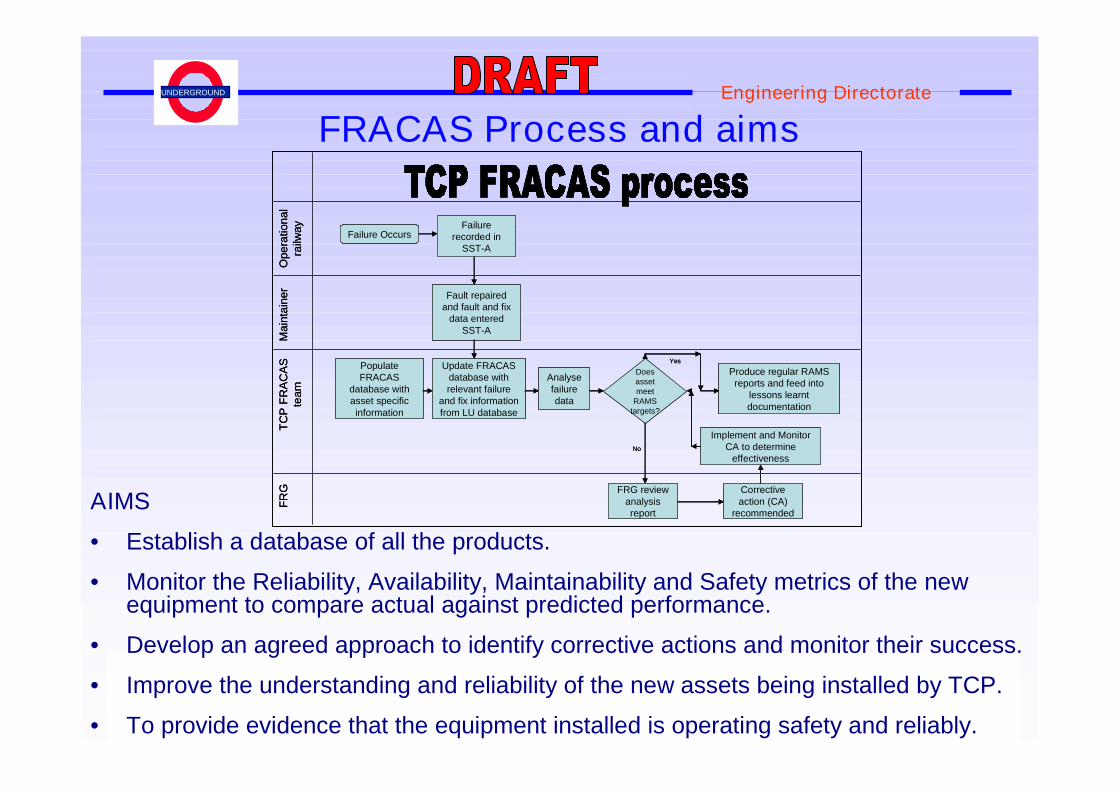
FRACAS Process and aims
AIMS
• Establish a database of all the products.
• Monitor the Reliability, Availability, Maintainability and Safety metrics of the newequipment to compare actual against predicted performance.
• Develop an agreed approach to identify corrective actions and monitor their success.
• Improve the understanding and reliability of the new assets being installed by TCP.
• To provide evidence that the equipment installed is operating safety and reliably.
Ope
ration
al
railw
ay
Failure OccursFailure
recorded inSST-A
Ma
inta
ine
rFault repaired
and fault and fixdata entered
SST-A
TC
PF
RA
CA
Ste
am
PopulateFRACAS
database withasset specificinformation
Update FRACASdatabase withrelevant failure
and fix informationfrom LU database
Analysefailuredata
FR
G FRG reviewanalysisreport
Doesassetmeet
RAMStargets?
Correctiveaction (CA)
recommended
Implement and MonitorCA to determine
effectivenessNo
Produce regular RAMSreports and feed into
lessons learntdocumentation
Yes
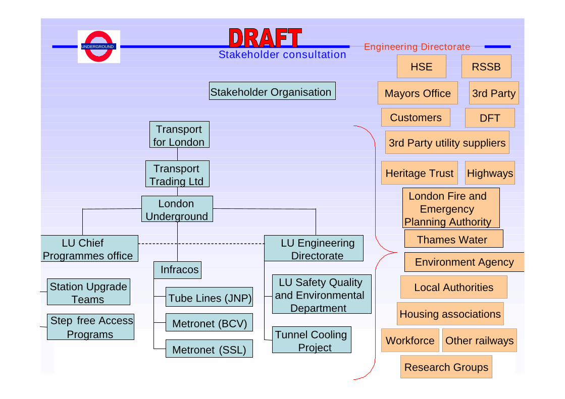
UNDERGROUND Engineering DirectorateStakeholder consultation
Stakeholder Organisation
London Fire andEmergency
Planning Authority
LU Safety Qualityand Environmental
Department
LU EngineeringDirectorate
Tube Lines (JNP)
Metronet (BCV)
Metronet (SSL)
Thames Water
Environment Agency
Station UpgradeTeams
Step free Access
Programs Tunnel CoolingProject
Transportfor London
Infracos
LU ChiefProgrammes office
TransportTrading Ltd
LondonUnderground
HSE
Mayors Office
RSSB
Customers
3rd Party
Housing associations
DFT
Highways
3rd Party utility suppliers
Other railways
Heritage Trust
Workforce
Research Groups
Local Authorities

UNDERGROUND Engineering Directorate
UNDERGROUND Engineering Directorate
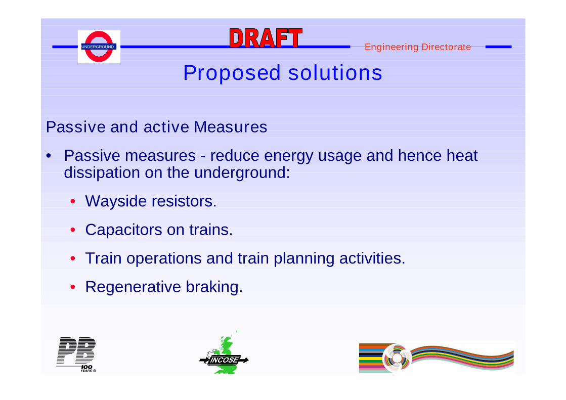
Proposed solutions
Passive and active Measures
• Passive measures - reduce energy usage and hence heatdissipation on the underground:
• Wayside resistors.
• Capacitors on trains.
• Train operations and train planning activities.
• Regenerative braking.
UNDERGROUND Engineering Directorate
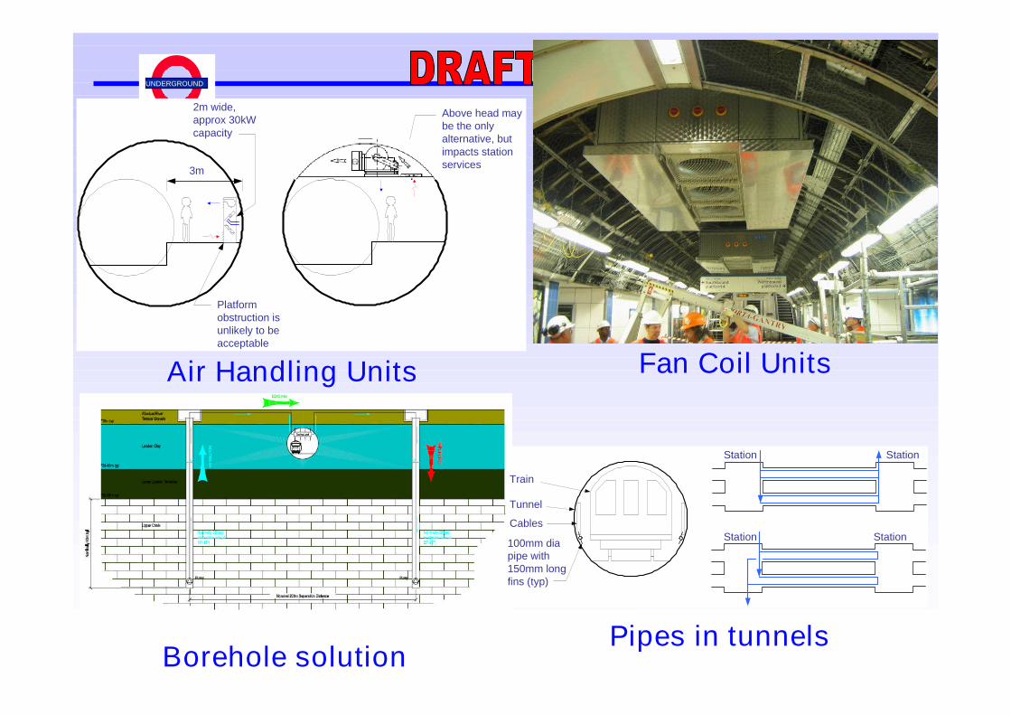
Fan Coil Units
Borehole solution
3m
2m wide,approx 30kWcapacity
Platformobstruction isunlikely to beacceptable
Above head maybe the onlyalternative, butimpacts stationservices
Air Handling Units
Train
Tunnel
Cables
100mm diapipe with150mm longfins (typ)
Station Station
Station Station
Pipes in tunnels
UNDERGROUND Engineering Directorate
Chillers
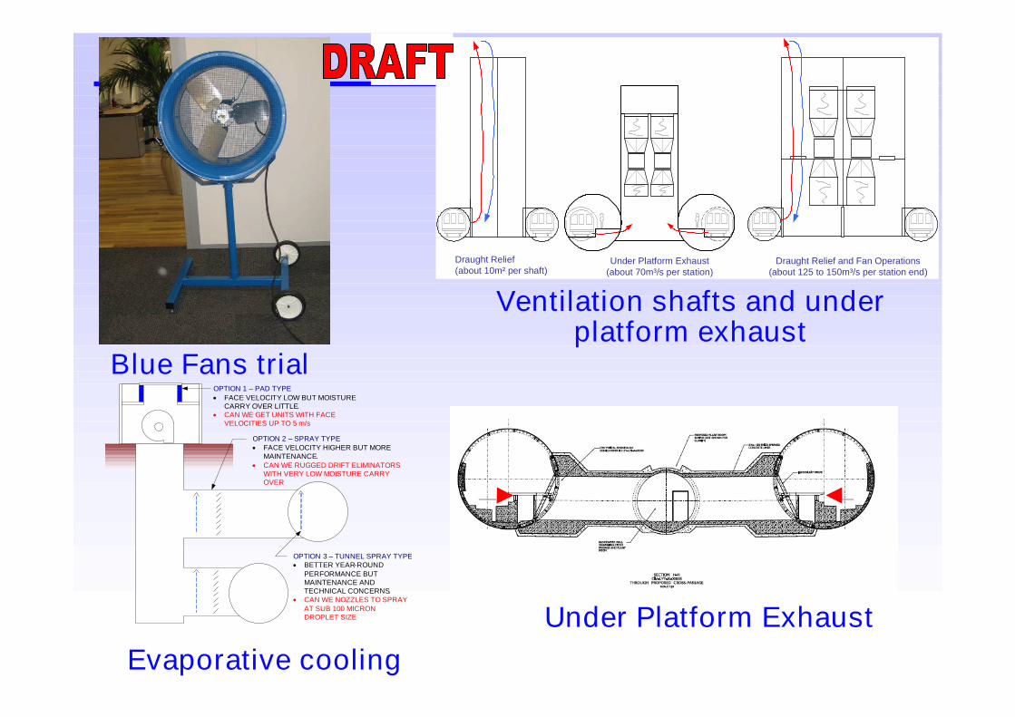
Blue Fans trial
Evaporative cooling
Draught Relief(about 10m² per shaft)
Under Platform Exhaust(about 70m³/s per station)
Draught Relief and Fan Operations(about 125 to 150m³/s per station end)
Ventilation shafts and underplatform exhaust
OPTION 1 – PAD TYPE
FACE VELOCITY LOW BUT MOISTURECARRY OVER LITTLE.
CAN WE GET UNITS WITH FACEVELOCITIES UP TO 5 m/s
OPTION 2 – SPRAY TYPE FACE VELOCITY HIGHER BUT MORE
MAINTENANCE. CAN WE RUGGED DRIFT ELIMINATORS
WITH VERY LOW MOISTURE CARRYOVER
OPTION 3 – TUNNEL SPRAY TYPE BETTER YEAR-ROUND
PERFORMANCE BUTMAINTENANCE ANDTECHNICAL CONCERNS.
CAN WE NOZZLES TO SPRAYAT SUB 100 MICRONDROPLET SIZE Under Platform Exhaust

UNDERGROUND Engineering Directorate

UNDERGROUND Engineering Directorate
Summary• Explained the complexity of the problem
• Explained how we are using Systems Engineeringin the Tunnel Cooling Programme to manage thenetwork wide, long term cooling challenge
• Showed examples of the proposed solutions
UNDERGROUND Engineering Directorate
Any Questions?