tunnelling in tectonic melanges – accomodating the...
TRANSCRIPT

1
TUNNELLING IN TECTONIC MELANGES – ACCOMODATING THE IMPACTS OF GEOMECHANICAL COMPLEXITIES AND ANISOTROPIC ROCK MASS FABRICS
E.BUTTON, G.RIEDMÜLLER, W.SCHUBERT, K.KLIMA, AND E.MEDLEY
E. Button
Institute for Rock Mechanics and Tunneling, Graz University of Technology, Rechbauerstrasse 12, 8010 Graz, Austria
Fax: +43 316 873 8618, e-mail: [email protected]
G. Riedmüller
Institute of Engineering Geology and Applied Mineralogy, Graz University of Technology, Rechbauerstrasse 12, 8010 Graz, Austria Fax: +43 316 873 6871, e-mail: [email protected]
W. Schubert
Institute for Rock Mechanics and Tunneling, Graz University of Technology, Rechbauerstrasse 12, 8010 Graz, Austria Fax: +43 316 873 8618, e-mail: [email protected]
K. Klima
Institute of Engineering Geology and Applied Mineralogy, Graz University of Technology, Rechbauerstrasse 12, 8010 Graz, Austria Fax: +43 316 873 6871, e-mail: [email protected]
E. Medley
Exponent Failure Analysis Associates, 149 Commonwealth Drive, Menlo Park, CA 94025, USA Fax: 650 328 3094, e-mail: [email protected]
Accepted (October 2003) for publication in the
Bulletin of Engineering Geology and the Environment Contact: Dr Edmund Medley, Exponent Failure Analysis Associates, 149 Commonwealth
Drive, Menlo Park, CA 94025 (650) 688 7107 [email protected]

2
Abstract Experiences from the construction of two shallow tunnels through a thrust melange are discussed. It is
shown that complex geological environments, such as a melange zone, requires continuous geological and
geotechnical characterisation as well as state of the art monitoring to comprehend the details of the melange’s
internal block / matrix structure and the effects on the excavation. The acquired data are used to determine the
appropriate key parameters that sufficiently describe the expected rock mass behaviour. We discuss how the
evaluation of three dimensional displacement data, combined with a continuous geological characterisation
allows the optimisation of a tunnel construction in a tectonic melange.
Key words Tunneling, Thrust melange, Rock mass characterisation, Displacement
monitoring
Introduction
Tectonic melanges (from French mélange, or “mixture”) are defined as chaotic,
heterogeneous geological mixtures of blocks, with different types and sizes, surrounded by
weaker sheared finer-grained rocks (Raymond and Terranova 1984). The highly deformed
“block-in-matrix” fabrics of melanges are formed by tectonic fragmentation and mixing of
rocks in convergent plate boundaries of orogenic belts, e.g. Alps, Himalayas, the west Taiwan
fold belt etc. In some mountain belts, such as the Californian Coast Ranges and the Taurus -
Zagros mountains of Turkey and Iran, they form expansive fault-bounded regions thousands
of square kilometres in area (Moore and Twiss 1995).
Over the last ten years, construction of tunnels has increased in mountainous regions of high
geological complexity, and tunnelling in tectonic melanges has become necessary.
Successfully developing this type of project challenges geologists, design engineers and
contractors.
The enormous heterogeneity of a melange poses severe engineering problems. For the
tunnelling community, one of the main construction problems is working with mixed face
conditions, in which the working face contains materials with different excavation
characteristics. This can have a significant impact on the excavation, for example
complicating the construction logistics by forcing the use of different excavation techniques
during a single excavation cycle, with attendant delays and cost increments. In our
experience, the main geotechnical problems result from the significant spatial variations in
rock mass stiffness and strength, which reduce the confidence of predictions, thereby

3
adversely affecting the engineering and construction operation (Püstow et al. 2001; Button et
al. 2002).
The heterogeneity of a melange rock mass, demands comprehensive characterisation, of the
geological, geometrical, mechanical and hydraulic properties, even more than in other rock
mass types. However, even when comprehensive investigations are performed, the
complexity of the internal block/matrix structure may prevent the geotechnical investigations
from yielding sufficiently precise rock mass models.
The rock mass strength of block-in matrix-rocks such as melanges, is mainly governed by
strength contrasts between the blocks and matrix, the sizes of blocks, and block volumetric
proportions (Lindquist 1994; Medley 1994a; Medley 1994b; Medley 1998; Medley and
Goodman 1994). The rock mass behaviour, particularly during tunnelling, is primarily
influenced by the local rock mass strength and very importantly by the location and size of
significant blocks (Button et al. 2002). Hence, deficiencies in rock mass models are typically
caused by a significant lack of geometrical and spatial information, particularly in accurate
information on block sizes, block shapes, and block locations, all of which are virtually
impossible to obtain in full.
Because of the often extreme difficulty of fully and accurately characterizing tectonic
melanges, a typical geotechnical description of a tectonic melange may simplify the
geological and geomechanical heterogeneity by assuming that the melange rock mass is a
chaotic “pseudo - isotropic mixture” (Marinos and Hoek 2000). This type of simplification
should be carefully assessed as recent experience from tunnel constructions in melanges of the
Austrian Alps has shown that mechanical complexity and fabric anisotropies (resulting from
the ductile – brittle tectonic development) can have a tremendous impact on the rock mass
behaviour during tunnelling (Button et al. 2002; Dissauer et al. 2002). This is especially true
when the block sizes approach the scale of the excavation. These features of a melange, which
are particularly important for the prediction of the rock mass behaviour during tunnelling, can
only be revealed by geotechnical investigations that are combined with detailed structural-
geological analyses and, during the excavation, by state-of-the-art techniques to interpret the
results of monitoring in real time. Such approaches, described in this paper, were developed
during work over the last decade with the Spital and Steinhaus tunnel projects that are
currently under construction in a thrust melange of the Austrian Alps.

4
The Spital and Steinhaus tunnels are dual-lane, twin bore tunnels constructed for the
Semmering expressway S6 (Figure 1). The Spital tunnel is approximately 2,500 m long with
approximately 500 m consisting of cut and cover construction. The distance between the
bores is about 50 m over most of the tunnel length. The maximum overburden is 90 m, but
averages 20 to 30 m. Construction of the tunnel started in September 1998 and was completed
in November 2002 after severe time and cost overruns, due to unexpected difficulties during
excavation (Dissauer et al. 2002) .
Figure 1
The Steinhaus tunnel is approximately 1,800 m long with approximately 100 m consisting of
cut and cover construction. The maximum overburden is 50 m, but averages 20 to 25 m. The
tunnel is scheduled to be completed in 2003 (Eberl 2002).
Regional Geology in the Area of the Spital and Steinhaus Tunnels
The tunnels are located within the “Semmering-Unterostalpine” nappe system. The tectonic
units, which are separated by pronounced detachment zones, include a polymetamorphic
crystalline basement and a low-grade metamorphic Mesozoic sequence (Neubauer and Genser
1990; Riedmüller et al. 2000). The tectonic melange was generated during thrusting within a
ductile crustal environment. Blocks of various sizes and lithologies, were emplaced within a
foliated matrix of intensely sheared phyllites. Significant blocks range in size from several
meters to more then 500 m in length. The blocks are typically lenticular in shape and are
oriented with their long axes sub-parallel to parallel to the NNW dipping foliation. Most block
/matrix contacts are either composed of brecciated rocks or highly sheared fine-grained clayey
gouge. Strike-slip faults associated with the Tertiary Mur-Mürztal fault zone overprint the
original structures formed during thrust tectonics. This combination of tectonic events has
created an extremely heterogeneous rock mass at the scale of the tunnel alignments, with a
spatially complex distribution of strength and stiffness (Figure 1).

5
Characterization of the Internal Structure of a Melange Rock Mass
Incorporating research results from rock mechanics and structural geology into the evaluation
of the rock mass and system behaviour provided a basis for understanding the complex spatial
relationships and their effect on the behaviour during excavations. The local behavior of a
melange rock mass is controlled by the size, distribution, and the position of the blocks related
to the excavation, as well as variations in the strength of the matrix, which in turn influence
the appropriate tunnel excavation and support methods.
Figure 2
Figure 3
Accordingly, in melange rock masses the geologist needs to make predictions about the rock
mass conditions ahead of and surrounding the excavation. The distribution of blocks and the
variation in matrix properties can be estimated and correlated with careful evaluation of the
observed rock mass conditions and their trends by understanding the types, kinematics, and
relative magnitudes of the tectonic deformations that created the anisotropic fabric of the
melange.
The typical anisotropic fabric of tectonic melanges, resulting from ductile to brittle
deformation histories, is found from the micro- to the mega-scale. The apparent scale
independence allows relatively small-scale observations made at successive faces during the
tunnel excavation to be extended to three-dimensional rock mass modelling and short-term
predictions ahead of the face. For example figure 2 shows a small block of rauwacke (cellular
dolomite) immediately surrounded by sheared graphitic phyllite and chlorite phyllite, which
was exposed during the excavation for the east portal of the Steinhaus tunnel. Figure 3 shows
a large quartzite block surrounded by sheared graphitic phyllite that was encountered during
the Steinhaus tunnel excavation at approximately station 400 of the south bore. On the basis
of geologic observations and interpretations, extensional and compressive domains due to

6
brittle faulting can be identified at small scales, which then provide information as to the
states of initial, pre-excavation stresses and ground conditions. For instance, extensional fault
kinematics, usually found in larger elongated blocks, indicates reduced lateral ground pressure
and attendant risks of ground water inflow and overbreak.
The geometry of blocks (aspect ratio and volume) is influenced by the original structures of
the parent rock mass such as bedding thickness, fault zone thickness, fault spacing and
roughness, etc., metamorphic reactions, the amount of local strain accumulated around the
blocks; and whether the deformation that occurred during formation of the melange was
ductile, transient, or brittle.
Research in structural geology suggests that the size and shape of blocks is a function of how
they were formed, their tensile strength, and the block/matrix strength contrasts. The latter
influences the transmission of tractions. Higher strength parent rock masses can result in
larger blocks with higher aspect ratio’s then weaker materials that will break apart more easily
(Mandal et al. 2001), frequently creating chains of smaller blocks separated by secondary
shear zones.
Experimental data show that most blocks in a frictional material become stable when they are
oriented at angles between 5° and 25° to the shear direction (Grotenhuis et al. 2002;
Mancktelow et al. 2002). Blocks with large aspect ratios tend to stabilize at the lower end of
this range. Blocks with smaller aspect ratios tend to be inclined with angles in the upper
portion of this range. Additionally, the long axes of some blocks may become sub parallel to
secondary shear zones. Shear localization is one process that will allow a blocks orientation to
stabilize (Grotenhuis et al. 2002). This process results in a stable geometric configuration
consisting of blocks surrounded on all sides by sheared matrix, the fabric that is typically
observed in tectonic melanges. The sheared, slickensided block/matrix contacts control the
shear strength of failure surfaces that may subsequently develop around the blocks (Grossauer
2001).
Evaluation of Monitoring Data and Rock Mass Behaviour
The geotechnical engineer must work with the geologist in evaluating displacement
measurements, as the system behaviour is governed to a great extent by the rock mass that is

7
not observed at the tunnel face. Therefore, by combining careful mapping and recording of
geotechnically and geologically relevant key parameters with the 3-D displacement data,
important features and indicators can be identified and used to determine excavation and
support methods for the upcoming sections.
The rock mass behaviour during excavation depends largely on the local volumetric block
proportion (ratio of representative block volume of to the relevant rock mass volume) in the
immediate vicinity of the excavation area, the sizes, shapes and positions of blocks, the
relative deformability and strength of blocks and matrix and the effect of ground water. On
the one hand the heterogeneity of a tectonic melange leads to stress concentrations in the
blocks, whereas, on the other hand, there will also be relatively high deformations in the
matrix during the tunnel excavation. The stress concentrations occurring in the blocks may
lead to sudden brittle failure of the blocks (Schubert and Riedmüller 2000 a, 2000 b) while
matrix deformation can be time dependent.
It is emphasised that the rock mass structure outside the excavation area dominates the rock
mass response. Isolated blocks within the excavation perimeter may contribute to the face
stability, but only temporarily influence the overall stability of the tunnel. Our evaluations of
displacement monitoring data, such as displacement vector plots, time histories and deflection
and trend lines (Schubert and Budil 1995; Vavrovsky and Schubert 1995; Steindorfer 1997;
Schubert et al. 2002), indicate that the displacement magnitudes generally increase with
decreasing block volumetric proportion. Furthermore, the position of the stronger blocks
relative to the perimeter of an excavation plays a key role in the behaviour of the surrounding
rock mass.
Figure 4
In Figure 4a the results of 3-D numerical simulations are displayed. The simulations were
performed with the numerical code BEFE (Beer 1999) assuming elastic material behaviour.
For this discussion we used these simulations as a simple model to demonstrate the general
response of a soft zone crossing the excavation (Grossauer 2001). The results in the upper
graph show the increase in the maximum stress at the sidewall, normalized by the vertical
stress, when entering and exiting the soft zone. The middle graph shows the increase in
settlements for the crown point. While the lower graph demonstrates how the vector

8
orientation (ratio of longitudinal deformation to settlements) changes when entering and
exiting the soft zone. Figure 4b shows the results of a 2-D simulation performed to investigate
the potential for stress concentrations in blocks depending on their location; also performed
with BEFE (Beer 1999). The stress concentration in a block intersected by the tunnel
excavation can clearly be seen.
An illustration of this phenomenon (typical for the behaviour in both tunnels) is provided
from our experience investigating the south bore of the Spital tunnel. Figure 5 shows the
documented geology presented as a plan view (lower) and a longitudinal section (upper) for
the south bore of the Spital tunnel from station 1700 to 1800 (Heim 2001). At about station
1,700 the tunnel excavation exited from a large marble block and entered a matrix dominated
section composed of sheared chlorite phyllites and graphitic phyllites with blocks of quartzite
and marble ). At approximately station 1,760, a quartzite block was observed in the upper left
section of the top heading. From station 1,775 to 1,785 another large quartzite block was
located in the bench. At station 1,790 a NE trending, high angle fault zone displaced this
block and overprinted the matrix rocks creating a complexly folded and sheared zone 20 m
thick. The excavation entered the next block dominated zone at about station 1,850.
Figure 5
Figure 6
Figure 7
Figure 8
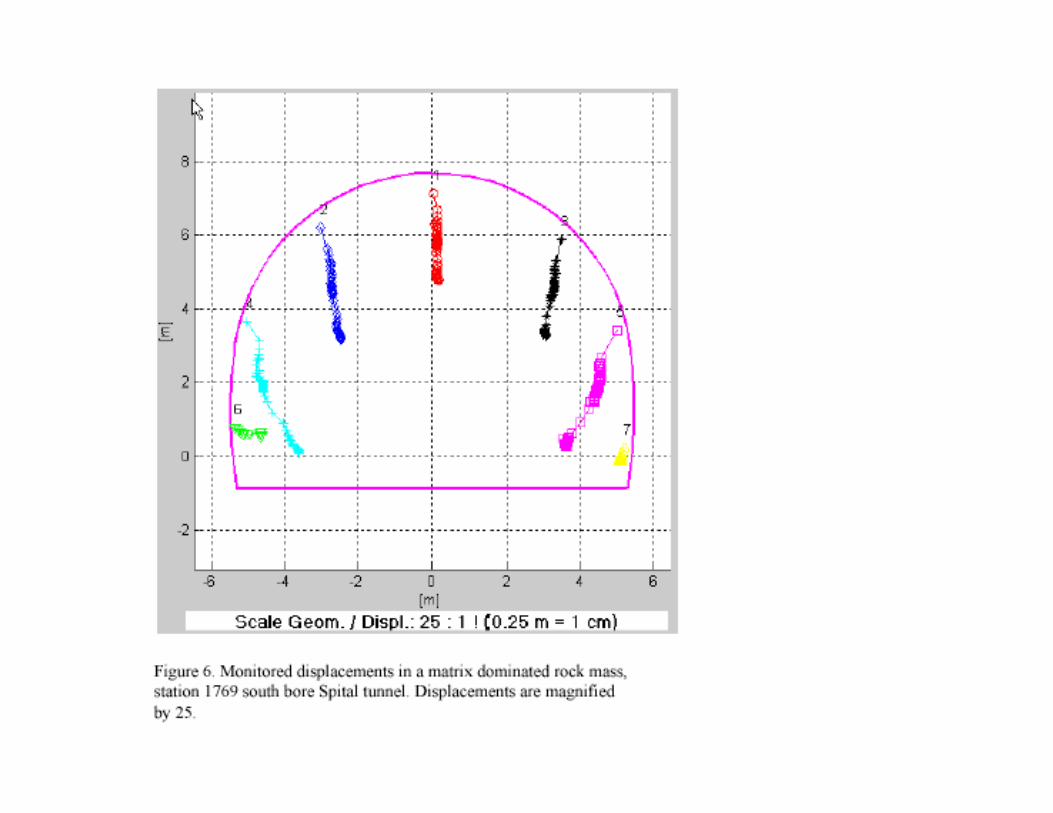
The displacement plots shown in the following sections were created with the program
GeoFit (Sellner 2000; Sellner and Schubert 2000; http://www.3-g.at). Figures 6 shows the
displacement vectors for the matrix dominated rock mass at station 1,769. This deformation
style is typical for these rock mass conditions. The deformation consists of more or less
homogeneous settlements with magnitudes in the range of 10 to 20 cm. The decreased
deformation magnitudes for points 6 and 7 is due to their later installation time during the
bench excavation.

9
Figure 7 shows the displacement vectors for a block-influenced rock mass at station 1,779.
The anisotropic deformation results from the size and position of the quartzite block
encountered during the bench excavation. The block extends from the rock mass at the right
side of the tunnel, across the bench ending at the left tunnel boundary. The block limited the
vertical settlements on the right side of the tunnel and initially on the left side. When the
bench excavation removed most of the block the left side displayed similar behaviour to the
previous measurement section. This considerable difference in displacement magnitudes
between left and right sides of the tunnel imposed a sufficient torque on the lining that caused
the shotcrete in the right upper sidewall to crack over a distance of 25 m (Figure 8).
Deflection lines are used to display the development of displacements with time and position
along the tunnel excavation. The deflection lines are created by connecting the
displacements at each measurement section that are recorded on the same day. A trend line is
created by extracting values from the deflection lines at a constant distance behind the
measurement section (Steindorfer 1997). The displacement trend lines assist in the short term
prediction techniques as discussed in (Steindorfer 1997; Schubert et al. 2002). In Figure 9,
deflection lines for the settlements of points 4 and 5 are displayed from station 1,720 to 1,850,
the approximate extent of the encountered brittle fault zone. The displayed measurements
begin with the settlements caused by the top heading excavation, and show the additional
deformations resulting from the bench excavation. There is some effect on the final
deformation magnitudes from the block encountered from stations 1,757 to 1,768 on point 4
while little effect is seen on point 5. The stabilizing effect of the block encountered between
stations 1,771 and 1,789 and the extent of the region which is influenced by it can clearly be
seen for both points.
The evaluation of deformations along the tunnel axis together with the results of geologic face
mapping allows one to clarify the influence of the complex structure of a tectonic melange on
the rock mass behaviour during the excavation of the tunnel.
Short term predictions of the rock mass conditions ahead of the tunnel face are based on
displacement analysis techniques (Schubert and Budil 1995; Vavrovsky and Schubert 1995;
Steindorfer 1997; Grossauer 2001; Schubert et al. 2002). Figure 10 shows the vector
orientation trend for both points 4 and 5 calculated 8 m behind the advancing face. There are
10
differences between the two plots that indicate that the rock mass qualities are different for
each side of the excavation, as shown in Figure 9.
Figure 9
Figure 10
A brief discussion on the interpretation follows. The “normal” vector orientation is between
8° and 10° against the excavation, which is in the range reported in previous evaluations
(Steindorfer 1997). Increasing trends indicate weaker material ahead of the face, while
decreasing trends indicate stiffer material. The slope indicates the relative difference between
the material properties as shown in Figure 4a. In extensive zones, the vector orientation will
return to the “normal” value before indicating the next transition. There is a good agreement
between the interpretation of the vector orientation trends and the observed geologic
conditions and system behaviour. Due to the complexity of the rock mass structure, it must be
emphasized that in combination with the geological mapping that multiple evaluation methods
must be applied and evaluated to make short term predictions in real time. In some cases it
may be necessary to verify the predictions by probing ahead of the face.
The techniques illustrated here require constant and consistent collection of real time data,
face mapping and analysis, which can only be achieved through cooperation between
geologists, engineers, contractors, and owners.
When tunnelling in a melange, severe problems can occur from unexpected ground water
inflows. Large blocks with sizes exceeding several tens of meters may act as aquifers, or
“perched water lenses”, and indeed, large blocks provide water in rural parts of Northern
California (Medley 1994). The stiff blocks typically have a higher fracture permeability and
storativity then the weak, soft matrix rocks. This situation can create significant water and
seepage forces between the blocks, matrix and the excavation, resulting in a high potential for
collapses. Several such critical situations associated with severe overbreaks were encountered
during the excavation of the Spital tunnel. One of these resulted in a short-term water inflow
up to 100 liters/sec leading to a top heading collapse (Dissauer 2002).

11
Determination of Support and Excavation Sequences
During the design phase, melange rock mass types must be defined considering possible block
locations and sizes with different material qualities. The defined rock mass types are then
used to evaluate the rock mass behaviour types considering the projects influencing factors.
Once rock mass behaviour types are defined, different support and excavation methods can be
evaluated (Schubert et al. 2001; Goricki 2002). Due to the extreme heterogeneity of melange
rock masses at the scale of tunnelling interest, the actual conditions will likely vary
considerably from those anticipated from the results of geological mapping and subsurface
investigations (exploration drilling and geophysical surveys). Because of the in-situ
heterogeneity, it is inappropriate and simplistic to use rock mass characterizations founded on
the principles of homogenising the rock mass behaviour from generic parameters collected
during investigations or at the tunnel face. In other words, classification schemes such as Q or
RMR (Barton et al. 1974; Barton 1998; Bieniawski 1989) will fail to adequately determine
optimum support requirements and appropriate excavation methods. Note that in blocky rock,
it is equally, if not even more cogently necessary to avoid a generic classification system to
detect and treat potentially sliding or falling blocks.
Despite high investigation efforts during the design phase, the selection of the appropriate
support and excavation methods, particularly in a tectonic melange, demands short term
predictions during construction. This prediction has to be based on a careful evaluation of
monitoring data and continuous updating of the three-dimensional geological model, which
must include a representative rock mass volume
The tunnel excavation in tectonic melanges is usually performed by subdividing the
excavation into top, bench and invert headings with a primary lining consisting regularly of
steel ribs, grouted bolts, shotcrete and wire mesh. Subdivision of the top heading and/or
additional face support may be necessary in sections dominated by weak matrix rocks. From
our experience, matrix dominated by clayey gouge typically contain swelling clay minerals
(Klima et al. 1988; Riedmüller 1978). Therefore, a strong invert support is recommended due
to the potential for volume increase by osmotic swelling as well as stress-induced shear
failures with high radial displacements (Einstein 2000).
Opportunities to reduce the support and increase round lengths when excavating larger
competent blocks have to be carefully checked by constantly reviewing displacement

12
monitoring data and performing short-term predictions of the ground ahead of the face. It is
vital that it be understood that larger blocks accumulate stresses, which under certain strength
and/or kinematic conditions, may cause an unexpected and sudden failure.
It is also emphasised that the abruptly changing rock mass conditions in a tectonic melange
require a strong but also ductile support, rather than the intuitively attractive option of
increased stiff support. Such ductile support can be achieved by installing yielding support
elements, such as “Lining Stress Controllers” which homogenise the stress distributions in the
lining as well as maximize the utilization of the shotcrete as its strength develops with time
(Moritz 1999; Schubert 1995; Schubert et al. 2000).
Conclusions
There is a small but growing appreciation amongst geo-practitioners of the often extreme
geological, geometric, geomechanical and geohydrological heterogeneity of tectonic
melanges and other block-in-matrix rocks. Any attempt to geotechnically homogenize the
highly complex geological environments of tectonic melanges by the commonly used
quantitative rock mass classification systems leads to an inappropriate design and
construction. Rather, tunnelling in a tectonic melange requires continuous modelling of the
spatial distribution of blocks and matrix ahead of the face and around the tunnel. This can be
achieved by now available state-of-the art monitoring and evaluation techniques combined
with geological face mapping which consider the key features of block-in matrix-rocks.
Strong variations in the displacements frequently lead to overstressing of rigid supports.
Consequently, ductile supports are recommended also for tunnels with low overburden.
Experience shows that blocks have a potential for sudden brittle failure due to the
accumulation of stresses during excavation advance. Using three dimensional displacement
monitoring and advanced evaluation techniques a prediction of the rock mass structure around
the excavation is possible even in such complex ground conditions as a tectonic melange. A
detailed knowledge about the location, size, and shape of blocks, as well as the anisotropic
matrix fabric during construction enable safe and economical tunnelling.
Acknowledgement: The research described in this paper was conducted as part of the
research project entitled “rock mass characterisation of phyllites for tunnelling”. The project
is funded by the FWF No. P14767- GEO.

13
The authors wish to thank Prof. R. E. Goodman for his critical review and useful suggestions.
References
BARTON N (1998) NMT support concepts for tunnels in weak rocks. In: Tunnels and Metropolises, Sao Paulo, Negro AJr,
Feirreira AA (eds), Balkema, Rotterdam, pp 273-279
BARTON N, LIEN R, LUNDE J (1974) Engineering classification of rock masses for the design of tunnel support. Rock
Mechanics 6(4): 189-236
BEER G (1999) BEFE user´s manual. Computer Software & Services International, Austria
BIENIAWSKI ZT (1989) Engineering rock mass classifications. Wiley, New York, 251 p
BUTTON EA, SCHUBERT W, RIEDMÜLLER G (2002) Shallow tunneling in a tectonic melange: rock mass characterization and
data interpretation. In: Proc. NARMS-TAC 2002, Mining and Tunelling Innovation and Opportunity. July 7-10. Hammah R ,
Bawden W, Curran J, Telesnicki M (eds), Toronto Canada, Univ. Toronto Press, Toronto, vol 2: 1125-1132
DISSAUER J, LEITNER A, MITTELBACH H (2002) Tunnel Spital – Tunnelbau in schwierigen Verhältnissen.- Felsbau 20/1: 40 –
48
EBERL G (2002) Tunnel als wesentliche Teile sicherer und umweltfreundlicher Straßen:- Felsbau 20/1: 8 – 11
EINSTEIN HH (2000) Tunnels in Opalinus Clayshale—A review of Case Histories and New Developments. Tunnelling and
Underground Space Technology, 15/1: 13-30
GORICKI A, SCHICK KJ, STEIDL A (2002) Quantification of the Geotechnical and Economic Risk in Tunneling. In:
Probabilistics in Geotechnics: Technical and Economic Risk Estimation, Graz, Austria, Sept. 2002, Glueckauf, Essen, pp.
483-490
GROSSAUER K (2001) Tunnelling in heterogeneous ground- numerical investigations of stresses and displacements. Masters
Thesis. Institute of Rock mechanics and Tunnelling. Graz University of Technology, Graz, 50 p
GROTENHUIS SM, PASSCHIER CW, BONS PD (2002) The influence of strain localisation the rotation behaviour of rigid objects
in experimental shear zones. Journal of Structural Geology, 24: 485-499
HEIM N (2001) Geologic Documentation for the Spital Tunnel, Quartalsbericht Nr. 02/2001. Technisches Büro für Geologie
und Geotechnik TBGG Dr. Norbert Heim, Vienna, Austria
KLIMA K, RIEDMÜLLER G, STATTEGGER K (1988) Statistical Analyis of Clay Mineral Assemblages in Fault Gouges. Clays
and Clay Minerals, 36/3: 227-283
LINDQUIST ES (1994) The strength and deformation properties of melange. PhD thesis, Dept.of Civil Engineering, Univ. of
California, Berkeley, 262 p
MANCKTELOW NS, ARBARET L, PENNACCHIONI G (2002) Experimental observation on the effect of interface slip on rotation
and stabilisation of rigid particles in simple shear and a comparison with natural mylonites. Journal of Structural Geology,
24: 567-585
MANDAL N, CHAKRBORTY C, SAMANTA KS (2001) Control of the failure mode of brittle inclusions hosted in a ductile matrix.
Journal of Structural Geology, 23: 51-66
MARINOS P, HOEK E (2000) GSI: A Geologically Friendly Tool for Rock Mass Strength Estimation. In: Geo Eng 2000, Proc.
Int. Symp. Melbourne, Ervin MC (ed), CD
MEDLEY EW (1994a) The engineering characterization of melanges and similar block-in-matrix-rocks (bimrocks). PhD
thesis, Dept. of Civil Engineering, Univ. of California, Berkeley, 387 p

14
MEDLEY EW (1994b) Using stereological methods to estimate the volumetric proportions of blocks in melanges and similar
block-in-matrix-rocks (bimrocks). In: 7th International IAEG Congress, Lisbon, Portugal; Balkema, Rotterdam, pp.1031 –
1040
MEDLEY EW (1998) Confronting geological complexity: Working with melange bimrocks. In: 8th International IAEG
Congress , Vancouver, Canada; Balkema, Rotterdam, pp. 227 – 233
MEDLEY EW, GOODMAN RE (1994) Estimating the block volumetric proportion of melanges and similar block-in-matrix-
rocks (bimrocks). In: Proc. 1st North American Rock Mechanics Conference (NARMS), Austin, Texas; Balkema, Rotterdam;
pp. 851 – 858
MOORE EM, TWISS JT (1995) Tectonics. Freeman, New York, 415 p
MORITZ BA (1999) A Ductile Support Method for Tunnels in Squeezing Rock. PhD thesis. Gruppe Geotechnik Graz,
Riedmüller G, Schubert W, Semprich S (eds), Graz University of Technology, Graz, 5, 112 p
NEUBAUER F, GENSER J (1990) Architektur und Kinematik der östlichen Zentralalpen. Mitt. Naturwiss. Ver. Steiermark, 120:
203 – 219
PÜSTOW H, RIEDMÜLLER G, SCHUBERT W (2001) Tunnelling in a tectonic melange of high structural complexity. Felsbau
19/4: 34 – 42
RAYMOND, LA, TERRANOVA T (1984) Prologue: The melange problem – a review. Geol. Soc. Am. Special Paper 198:1-5
RIEDMÜLLER G (1978) Neoformations and Transformations of Clay Minerals in Tectonic Shear Zones. Tschermaks
Mineralogische und Petrographische Mitteilungen, Springer, 25: 219-242
RIEDMÜLLER G, SCHUBERT W, GORICKI A, PÖLSLER P (2000) Investigation strategies for the design of the Semmering base
tunnel. Felsbau, 18/4: 28 – 36
SCHUBERT W (1995) Dealing with Squeezing Conditions in Alpine Tunnels. Rock Mech. Rock Engng, 29(3): 145-153
SCHUBERT W, BUDIL A (1995) The Importance of Longitudinal Deformation in Tunnel Excavation. In: Proceedings 8th Int.
Congress on Rock Mechanics (ISRM), Tokyo, Balkema, Rotterdam, pp 1411-1415
SCHUBERT W, GORICKI A, BUTTON, EA, RIEDMÜLLER G PÖLSLER P, STEINDORFER A, VANEK R (2001) Excavation and
Support Determination for the Design and Construction of Tunnels. In: ISRM Reg. Symp. Eurock 2001, Espoo, Finland.
Rock Mechanics a Challenge for Society, Särkkä P, Eloranta P (eds), Balkema, Rotterdam, pp 383 –388
SCHUBERT W, MORITZ BA, SELLNER P (2000) In: Tunnelling Methods in Squeezing Ground. In: Proceedings Geo Eng 2000,
An International Conference on Geotechnical and Geological Engineering, Melbourne, Australia, pp 19-24
SCHUBERT W, RIEDMÜLLER G (2000a) Tunnelling in Fault Zones - State of the Art in Investigation and Construction. Felsbau
18/2: 7-15
SCHUBERT W, RIEDMÜLLER G (2000b) Tunnelling in Fault Zones - Innovative Approaches. In: Pacific Rocks 2000, Proc. Int.
Congr. Seattle, Girard, Liebman, Breeds, Doe (eds) Balkema, Rotterdam, pp 113-124
SCHUBERT W, STEINDORFER A, BUTTON EA (2002) Displacement monitoring in tunnels- an overview. Felsbau 20/2: 15-23
SELLNER P (2000a) Prediction of displacements in tunneling. Ph.D thesis, Gruppe Geotechnik Graz, Riedmüller G, Schubert
W, Semprich S (eds), Graz University of Technology, Graz, 9, 129 p
SELLNER P (2000b) Prediction of displacements in tunneling. In: Geo Eng 2000, Proc. Int. Symp. Melbourne, Ervin MC (ed),
CD
STEINDORFER A (1997) Short term prediction of rock mass behaviour in tunnelling using advanced analysis of displacement
monitoring data. PhD thesis. Gruppe Geotechnik Graz, Riedmüller G, Schubert W, Semprich S (eds), Graz University of
Technology, Graz, 1, 111 p
VAVROVSKY GM, SCHUBERT P (1995) Advanced analyses of monitored displacements opens a new field to continuously
understand and control the geotechnical behavior of tunnels. In: Proceedings 8th Int. Congress on Rock Mechanics (ISRM).
Tokyo, Balkema, Rotterdam, pp 1416-1420