tuomas matti juhani kuusisto re-routing of cooling …
TRANSCRIPT

Tuomas Matti Juhani Kuusisto
RE-ROUTING OF COOLING WATER PI-
PELINE
Tekniikka ja liikenne
2011
2
OPENING WORDS
This thesis has been done in co-operation with Wärtsilä Finland Oy, Power Plant
engineering management office. I have been working for Wärtsilä as a summer
trainee for 2 summers now. In the summer of 2009 I worked as a machinist and
got familiar with production. I machined cylinder heads for Wärtsilä 32 engines.
In the following summer in 2010 I was a mechanical supervisor trainee in power
plants. I was working in a project in Maracanau, Brazil. There we were building a
power plant with eight Wärtsilä W20V46F engines and it was producing electrici-
ty for power-distribution network. With this experience I had quite a good basis
for doing my thesis on power plants.
I want to thank my teachers and different employees in Wärtsilä who have helped
me with my thesis.
Vaasa 15.3.2011
Tuomas Kuusisto

3
VAASAN UNIVERSITY OF APPLIED SCIENCES
Kone- ja tuotantotekniikka
ABSTRACT
Author Tuomas Kuusisto
Title Re-routing of cooling water pipeline
Year 2011
Language English
Pages 40 + 1 Appendices
Name of Supervisor Lotta Saarikoski
This thesis was made for Wärtsilä Finland Oy department of Power Plants. The
purpose of this thesis was to compare different solutions and to find the best and
cost-efficient solution for cooling water pipelines when radiators were located on
the roof of the power plant.
Making this thesis began by gathering all the possible solutions together and di-
vides into different groups depending on the solution. There were five different
groups and five different solutions were selected for a closer inspection. While
searching the best route for cooling water pipelines I gathered information by in-
terviewing designers, pipe-experts and engineers.
The result is a well-defined matrix table where the comparison and all the differ-
ent pipeline solutions were gathered. Prices for pipelines (€/m and €/kg), entry to
Power House, entry from top or under the hall and directness were taken into ac-
count in the comparison. The result of this thesis is good basis to start standardiz-
ing the certain solution. The matrix is not included in this thesis because the in-
formation is classified.
Keywords: Wärtsilä, cooling system, power plants, research

4
VAASAN UNIVERSITY OF APPLIED SCIENCES
Kone- ja tuotantotekniikka
TIIVISTELMÄ
Tekijä Tuomas Kuusisto
Opinnäytetyön nimi Jäähdytysvesiputkiratkaisujen vertailu ja suunnittelu
Vuosi 2011
Kieli englanti
Sivumäärä 40 + 1 liite
Ohjaaja Lotta Saarikoski
Tämä päättötyö tehtiin Wärtsilä Finland Oyj Power Plants yksikölle. Tavoitteena
oli vertailla eri ratkaisutapoja ja löytää paras ja edullisin ratkaisu jäähdytys-
vesiputkistolle, kun jäähdyttimet sijaitsivat voimalaitoksen katolla.
Päättötyön tekeminen alkoi keräämällä kaikki tämän hetkiset ratkaisumahdolli-
suudet yhteen ja jakamalla ne ryhmiin käytetyn ratkaisumallin mukaan. Ryhmiä
tuli 5 ja sieltä valittiin 5 erilaista ratkaisua lähempään tarkasteluun. Parasta putki-
tusreittiä suunniteltaessa tietoa haettiin haastattelemalla suunnittelijoita, putkiasi-
antuntijoita ja insinöörejä.
Lopputuloksena saatiin selkeä matriisitaulukko, johon on koottu kaikki erilaiset
putkitusmahdollisuudet ja niistä tehty vertailu. Vertailussa on otettu huomioon
putkitushinnat (€/m ja €/kg), putkituksen sisääntuloreitti, sisääntulo halliin ylä- tai
alaosasta sekä reitin suoruus. Tämän tutkimustyön tuloksia on helppo käyttää jat-
kossa, kun tiettyä putkitusratkaisua aletaan standardoida. Taulukkoa ei ole liitetty
tähän työhön, koska tiedot ovat luottamuksellisia.
Asiasanat: Wärtsilä, suunnittelu, jäähdytys

5
USED TERMS AND ABBREVIATIONS
CW Cooling water
PH Power House
HT High Temperature
LT Low Temperature
EMO Engineer Management Office
EPC Engineer, Procure and Construct
EEQ Engineered Equipment Delivery
IDM Integrated Document Management
FTH Fuel Treatment House
EAM Engine Auxiliary Modules
W32 Wärtsilä 32 Engine
SG Gas engine

6
CONTENT
OPENING WORDS
ABSTRACT
TIIVISTELMÄ
TERMS AND ABBREVATIONS
1 INTRODUCTION ............................................................................................ 8
1.1 The objective ............................................................................................. 8
1.2 Research Plan ............................................................................................ 8
1.3 Thesis structure ......................................................................................... 8
2 INTRODUCTION OF THE COMPANY ........................................................ 9
2.1 Wärtsilä Corporation ................................................................................. 9
2.2 Power Plants............................................................................................ 10
3 COSTS IN THE EARLY STAGE OF THE PROJECT ................................. 11
4 COOLING SYSTEM ..................................................................................... 13
4.1 Basics ...................................................................................................... 13
4.2 Cooling Water System Components ....................................................... 14
4.2.1 Air & Dirt Separators .................................................................. 14
4.2.2 Cooling water temperature control.............................................. 15
4.2.3 Heat Exchanger ........................................................................... 15
4.3 Radiators ................................................................................................. 16
4.4 Radiator Locations .................................................................................. 17
4.4.1 Radiator Field .............................................................................. 17
4.4.2 Radiators on the Roof.................................................................. 18
5 RE-ROUTING OF COOLING WATER ....................................................... 19
5.1 The Starting Point for the Re-Routing .................................................... 19
5.2 Installation Groups .................................................................................. 20
5.3 Collecting Information for the Comparison ............................................ 20
5.4 Route from the Engine to the Radiator ................................................... 21
5.5 Pre-fabricating......................................................................................... 22
5.5.1 Basics .......................................................................................... 22
5.5.2 Pre-fabrication Cost Estimate for UTE Suape’s Solution ........... 24
6 COMPARISON OF DIFFERENT SOLUTIONS .......................................... 26

7
6.1 Basics ...................................................................................................... 26
6.2 First group ............................................................................................... 27
6.3 Second Group.......................................................................................... 29
6.4 Grading for the First Group .................................................................... 31
6.4.1 UTE Suape .................................................................................. 31
6.4.2 Attock Gen Limited..................................................................... 32
6.4.3 Ewekoro ...................................................................................... 33
6.5 Grading for the Second Group ................................................................ 34
6.5.1 UTE Linhares .............................................................................. 34
6.5.2 Al-Katrana ................................................................................... 35
7 RESULTS AND CONCLUSION .................................................................. 36
7.1 Results ..................................................................................................... 36
7.2 Future research ........................................................................................ 37
7.3 Reliability ................................................................................................ 37
7.4 Conclusions ............................................................................................. 37
REFERENCES ...................................................................................................... 38
LIST OF APPENDICES ....................................................................................... 40

8
1 INTRODUCTION
1.1 The objective
This thesis was made for Wärtsiä Finland Oy, unit of Power Plants. The objective
of this thesis was to find out the easiest and cost efficient route for Cooling Water
(CW) pipes from engine to radiator when the radiators are located on the roof of
the power plant. The engines are in the Power House and their main purpose is to
produce electricity for power-distribution network. There are many different in-
stallation ways for CW pipes when the radiators have been installed on the roof
and this has been a problem. Now we are trying to find the best solution for CW
pipes.
This subject was given by EMO group. Engineering Management Office (EMO)
is established as a result of the Cost down Project. EMO incorporates the previous
Documentation Organization. The objective is to manage the customer solution
engineering process including partnerships with engineering companies, such as
Citec Oy.
1.2 Research Plan
The Research starts by collecting all the different solutions of CW routes from
engine to radiators in the power plants delivered by Wärtsilä and dividing these
into different groups depending on the installation ways. For this thesis informa-
tion were collected by interviewing designers, engineers and pipe experts who
have experience in this type of installation. Costs for different solutions were ob-
tained from Citec Oy which has all information of pipelines.
1.3 Thesis structure
Thesis has been divided into eight different chapters. The chapters one, two and
three deals the company and theory of this subject. In the chapter four we can see
the principles of cooling system. The chapter five deals cooling water re-routing
and researching methods. In the chapter six we can see the comparison of differ-
ent solutions and in the chapter seven results and conclusions.

9
2 INTRODUCTION OF THE COMPANY
2.1 Wärtsilä Corporation
Wärtsilä was founded in 1834 in city of Tohmajärvi, East Finland. Today,
Wärtsilä has over 170 years of experience in different power solutions for marine
and energy markets. In 2010, Wärtsiläs net sales were EUR 4,553 million and
employed 17,528 employees in 160 locations in 70 countries around the world.
Net sales consist of Ship Power with share of 26%, Services with share of 40%
and Power Plants with share of 34%. Wärtsilä is listed on the NASDAQ OMX
Helsinki, Finland. A figure of Wärtsilä’s and its areas of business is given below.
/01/, /02/
Figure 1. Wärtsilä’s areas of business /10/
Wärtsilä has operations in three different areas of business – Ship Power, Services
and Power Plants. Ship Power provides different solution for marine markets,
such as engines, generating sets, reduction gears, propulsion equipment, automa-
tion and power distribution systems. Wärtsilä Power Plants offers flexible power
plants for the decentralized power generation market. Wärtsilä Services supports
its customers throughout the lifecycle of their installations.

10
2.2 Power Plants
Wärtsilä is a leading supplier of power plants for the decentralized power genera-
tion market and for the oil & gas industry. Its product portfolio consists of power
plants, solutions for oil & gas industry and related support services with an output
range of 1 to 300 MW. Wärtsilä deliver more than 2000 MW of power plants
every year. There are four different kinds of power plant solutions.
Gas power plants
Oil power plants
Combined heat & power plants
Biopower /06/
Wärtsilä’s values are presented in the figure 2.
Figure 2. Wärtsilä's values /8/
These days Wärtsilä has outsourced everyday designing and diagram drawing to
Citec Oy. There are a lot of matters which should be taken into consideration
when designing a power plant. The power output, fuel used and location of the
radiators are a few examples that cause differences in the design.

11
3 COSTS IN THE EARLY STAGE OF THE PROJECT
The control of the costs is especially important when the project is in definition
and planning phase. It is very important that the wideness, the resources, the time
scale and many other things are decided before the project starts. These decisions
define the whole structure of the costs and the budget of the project. /11/
In figure 3 it can be seen how important it is to define the costs in the beginning of
the project. Most of the projects costs will be determined by the solutions which
have been made in the early planning stage of the project. A possibility to influ-
ence the costs of the project will become weaker after the project is started. As the
starting point is defined in the beginning, the solutions which have already been
made become harder to change and more expensive. /11/
Figure 3. Actual costs and influence possibilities on the costs. /9/

12
Figure 4 below shows the importance and number of the decisions during the
project. The number of the decisions in the beginning is small but the importance
of these is great.
Figure 4. The importance and number of decisions in the life span of the project.
/11/
For example, the approval of the projects scale and investment decisions in the
beginning creates limits for upcoming costs. The projects sale price may become
too low if the delivery company underestimates the costs while making the offer,
therefore it can be an unprofitable project. When the project moves on the number
of decisions increases but the significance of a single decision is much smaller.
/11/
It is very important that the costs are defined in the beginning of the project. The
good planning in the beginning can save a lot of money and time in the project.
Changing the decisions is a lot harder after the project has been started.

13
4 COOLING SYSTEM
4.1 Basics
A cooling system of a power plant consists of five different parts: air & dirt sepa-
rators, cooling temperature control, cooling towers, heat exchangers, and radia-
tors.
The main purpose of the engine cooling system is to remove the generated heat
made by the engine and keep the lubricating oil at a normal temperature. A sec-
ondary function is preheating the engine block before starting. The cooling water
system removes heat from four main sources of heat in a diesel/gas engine:
Cylinder jacket and cylinder head cooling
High Temperature charge air cooler (HT CAC)
Low Temperature charge air cooler (LT CAC)
Lube oil cooler (LOC)
The circuit of cooling system can be seen in figure 5.
Figure 5. Cooling water system with radiator cooling. /3/

14
4.2 Cooling Water System Components
4.2.1 Air & Dirt Separators
The spirovent air & dirt separator is a standard component in the EAM. The de-
sign makes it possible for the separator to remove air bubbles that rise up and col-
lect into the air chamber and the dirt particles that sink onto the bottom of the dirt
chamber. See the operational principle in the figure 7 and location in the figure 6.
/3/
Figure 6. Spirovent air & dirt separator installed in EAM. /3/
Figure 7. Spirovent air & dirt separator. /3/

15
4.2.2 Cooling water temperature control
The cooling water temperature control in the engine is done by controlling the po-
sitions of HT and LT 3-way valves (TCVs) to get water of the optimal tempera-
ture into the engine. The primary cooling system which can be commonly used by
radiators, the cooling tower or some special cooling arrangement is advised to be
controlled with the help of variable frequency drives in order to match it with the
3-way valve control enabling optimized cooling control. See the typical remote-
controlled 3-way valve in figure 8. /3/
Figure 8. Remote-controlled 3-way valve. /3/
4.2.3 Heat Exchanger
When we want to recover as much energy produced by the engine as possible, a
heat exchanger should be installed in the condensate line before the condensate
returns to the feed water tank. In this exchanger the heat will pass from the HT
water engine system to the condensate water of the waste heat recovery system.
See picture of heat exchanger in the figure 9. /3/
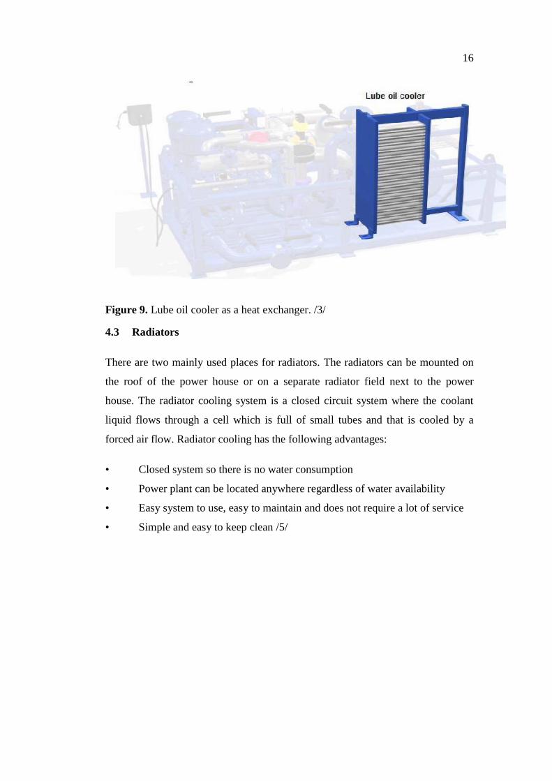
16
Figure 9. Lube oil cooler as a heat exchanger. /3/
4.3 Radiators
There are two mainly used places for radiators. The radiators can be mounted on
the roof of the power house or on a separate radiator field next to the power
house. The radiator cooling system is a closed circuit system where the coolant
liquid flows through a cell which is full of small tubes and that is cooled by a
forced air flow. Radiator cooling has the following advantages:
• Closed system so there is no water consumption
• Power plant can be located anywhere regardless of water availability
• Easy system to use, easy to maintain and does not require a lot of service
• Simple and easy to keep clean /5/

17
4.4 Radiator Locations
4.4.1 Radiator Field
The radiator field is the commonly used solution. Its advantages are:
Easy to build and work with
Easy to maintain
The disadvantages of the radiator fields are:
Pipe costs are high
Takes a lot of space in the area
Cooling is not so efficient as in the solution with radiators on roof
In the figure 10 we can see a radiator field solution.
Figure 10. Radiator field in a power plant, Brazil.

18
4.4.2 Radiators on the Roof
When the space is limited, the radiators are usually mounted on the roof of the
power house. A closer inspection for this solution is in chapter 5. In the figure 11
we can see radiators on the roof solution.
Figure 11. Radiators on the roof in a power plant, Brazil.

19
5 RE-ROUTING OF COOLING WATER
5.1 The Starting Point for the Re-Routing
The objective of this thesis was to find out the easiest and most cost efficient route
for CW pipes from the engine to the radiator when the radiators are located on the
roof of the power plant. There are many different installation ways for CW pipes
when the radiators have been installed on the roof. It was agreed that a matrix
should be produced as a result where we can see all the different installation ways
and all the necessary specifications, such as entry to PH, entry from top or under
the hall, directness, and price for €/m and €/kg. The matrix is not included to this
thesis because the information is classified.
Information and documents were collected of power plant projects that had radia-
tors on the roof. The Excel file of 36 projects and there was a section where the
projects could be divided into two parts, radiators on the roof or not. With a help
of a web-based IDM system, we could find 36 projects and we started to collect
layout drawings from the cooling systems. Some of the projects were not deli-
vered as EPC (Engineer, Procure and Construct) type so the project folder was
usually empty. That kind of projects is called EEQ (Engineered Equipment Deli-
very). It means that Wärtsilä only delivers the equipment and the customer builds
the engine hall and other buildings by themselves. EEQ projects were excluded
from this comparison.

20
5.2 Installation Groups
We got 13 projects the drawings of which we were able to find. We printed out
the layouts and started to divide the different installation ways into different
groups. We got the following groups:
1. CW pipes enter the hall from the upper side of the hall and through the
wall. A direct line from each radiator group to the engine.
2. CW pipes enter the hall from the lower side of the hall and through the
wall. A direct line from each radiator group to the engine.
3. CW pipes enter the hall from the lower side of the hall, but first the CW
pipes are collected into a group on the roof and on the ground and divided
for each engine.
4. CW pipes enter the hall from the upper side of the hall and through the
wall, but first the CW pipes are collected into a group on the roof and in-
side the hall divided for each engine.
5. CW pipes enter the hall through the roof. A direct line from each radiator
group to the engine.
We took 13 different projects for a closer inspection. We excluded three projects
right away because the design was so unique that it was not good for this compar-
ison and ten projects were taken for the comparison. We started to edit the matrix
and arranged the projects by their delivery year. We printed out the matrix and
used it for the interviews.
5.3 Collecting Information for the Comparison
We had a look at different installation ways and made a small grading for each of
them. Interviews were started by collecting the names and locations of designers,
supervisors and project engineers. A questionnaire was drawn up with a few sim-
ple questions regarding installation ways and their advantages and the disadvan-
tages and an opportunity to give a proposal for any improvements. Six different
designers and engineers were interviewed. Eight good answers were received
from around the world, which was a good basis for the comparison.

21
In the comparison the interviewees were comparing two different solutions: radia-
tors on the roof and the radiator field solution. While interviewing, notes were
taken and all the advantages and the disadvantages were gathered together. The
designers pointed out the critical spots from the layouts. There were a lot of dif-
ferent kinds of opinions. Especially the route from the engine to the radiator and
the pre-fabricating provoked a lot of discussion.
Advantages when the radiators are on the roof:
Air venting piping easy to make from the radiators to the expansion vessel
Higher efficiency
CW pressures are better, less CW air problems
Tank yard, FTH, the unloading station and the other buildings can be built
closer to the Power House. Therefore less space needed for the plant, less
piping, fewer cables and less pipe supports
Disadvantages when the radiators are on the roof:
More complicated construction work, such as the roof, the steel structures,
the roof ventilation units and the platforms
CW piping inside the power house requires a lot of working hours
Working on the roof. You have to cover the roof from welding splashes
and sparks
More leaking possibilities due to the lead-ins
Possible extra insulation for the HT water pipelines
5.4 Route from the Engine to the Radiator
The location of the radiators in the old design is very wide. There have not been
any standardized designs for CW pipe routes. Designers have taken old models
and edited them for their own projects. In this way, all possible faults will also
follow to the other projects, which is not good. Now we are researching the best
route for CW pipes. The different solutions were divided into different groups and
most of the solutions belonged to group number one. That is very commonly used

22
and most of the new projects are using this solution. Its advantages are short route
from the radiator to the engine and it does not need any lead-ins because the entry
is next to the engine hall through the wall. Its disadvantages are that when the CW
pipes go inside the PH, working with the pipes is very difficult and it takes a lot of
man hours. Also logistics can cause some problems for the installation. If the en-
gines come onto the site early and the building of power houses starts when the
engines are already inside, the installation work for CW pipes will be very diffi-
cult. There are, for example, exhaust gas pipes, EAM modules and charge air inlet
tubes in the way when you are mounting the CW pipes. If we are using SG (Gas
Engine) engines it is even more difficult. SG engines use gas as their fuel so they
do not need any separator for the fuel. The lack of separator means, that there is
no second crane like in a HFO engine. A crane helps when mounting the pipes
inside the PH.
5.5 Pre-fabricating
5.5.1 Basics
One other thing that was researched by interviewing was the pre-fabricating of the
CW pipes. It is not the first time when Wärtsilä is using pre-fabricated pipes. They
have used in projects with a short delivery time or when fabricating at the site has
been very expensive.
Advantages of pre-fabricating:
Fast to mount
Pipes are cleaner because of less welding seams
Less possible leaking points
Easier to clean (flushing and pickling)
Installation is cheaper
Disadvantages of pre-fabricating:
Logistics gets more complicated
Installation requires more accuracy

23
Possibly more Change Order work
Expensive
As we can see from above, there are some advantages and disadvantages. Logis-
tics will become more complicated because all the pre-fabricated pipes have to be
numbered very well. Also organizing the pipes into a container is more compli-
cated due to the pre-fabricated angles, etc. Installation work will also be more dif-
ficult. Pictures and layouts have to be followed and ensured that the right pipe is
in the right place. If the supervisors and the subcontractor do not pay enough at-
tention to the installation work, there is a possibility that the heads of the pipes do
not match and the subcontractor tries to do a change order. Change order work
pays extra for the company.
The pre-fabricated pipes are good for a project with a short delivery time. It saves
time because there is not so much welding work. Generally pipes are cleaner be-
cause the angles are made by bending. This helps when cleaning, flushing and
pickling the pipes. Welding seam is a very critical spot when pickling. Usually the
hardest place to clean is the welding seam. By reducing welds the cleaning proce-
dure is faster and easier.
It depends on the country as well, if there are any reasons to use pre-fabricated
pipes or not. Wärtsilä sells power plants all over the world. The price level varies
widely between different countries. For example, work in Canada is much more
expensive than in Brazil or in Pakistan. If Wärtsilä sells a power plant to Canada,
it is not self-evident that it saves money if some of the products are pre-fabricated.
There are also different Labor Productivity indices between countries. See list of
Labor Productivity indices in table 1.

24
Table 1. World Labor Productivity. /7/
For example, if you manufacture one part in Finland and it takes an hour, but if
you manufacture that same part in Ghana it takes about three times longer. This is
why you have to calculate the prices very well.
5.5.2 Pre-fabrication Cost Estimate for UTE Suape’s Solution
We got one cost estimate for cooling water pipes. For the price were included:
Material
Work (bending, welding, sawing for certain dimensions and marking of
the pipes)
Painting
Cost estimate does not include:
Packing/container

25
The pipes are made so well in Finland that at the site the pipe clips only have to be
assembled and the pre-fabricated pipes welded back together regarding the marks.
The total amount of the welds for DN100 and DN 200 pipes were 173 pieces. If
we pre-fabricate these pipes we can reduce the amount of welds to 64 pieces. One
welding seam takes about two hours to be made. By pre-fabricating we can reduce
the production time about 218 hours for one engine. For this calculation the
smaller pipes from the expansion vessel is not included. The cost estimate is not
included to this thesis because the information is classified.
26
6 COMPARISON OF DIFFERENT SOLUTIONS
6.1 Basics
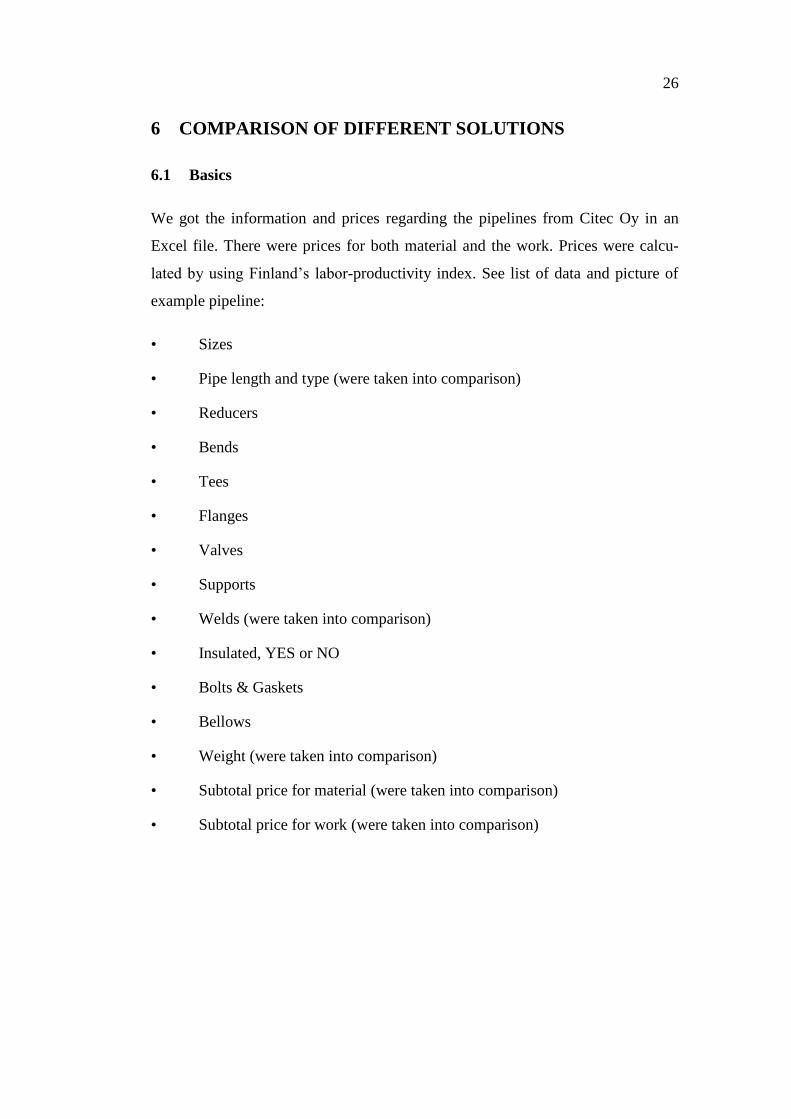
We got the information and prices regarding the pipelines from Citec Oy in an
Excel file. There were prices for both material and the work. Prices were calcu-
lated by using Finland’s labor-productivity index. See list of data and picture of
example pipeline:
• Sizes
• Pipe length and type (were taken into comparison)
• Reducers
• Bends
• Tees
• Flanges
• Valves
• Supports
• Welds (were taken into comparison)
• Insulated, YES or NO
• Bolts & Gaskets
• Bellows
• Weight (were taken into comparison)
• Subtotal price for material (were taken into comparison)
• Subtotal price for work (were taken into comparison)

27
Prices were calculated for five different solutions that were selected for this com-
parison. Key figures were pipe length, weight, and prices for material and work.
There were some problems in the comparison because of the number of the radia-
tors. The new design uses six radiator sets instead of four radiator sets in the old
one. Prices were calculated for one radiator set so that the prices are comparable.
The differences between the different solutions were quite remarkable. The solu-
tions were divided into two different groups depending on the engine type. In the
first group, there were Wärtsilä 46 and Wärtsilä 50 engines, mainly using DN200
pipes. In the second group, there were Wärtsilä 32 and Wärtsilä 34SG engines,
which mainly use DN150 pipes.
6.2 First group
Three different solutions were in the first group. They were UTE Suape, Attock
Gen Limited and Ewekoro projects. Suape and Attock had a direct line from the
radiators to the engine, where Ewekoro was collecting the pipes together on the
roof and dividing them again on the ground. In the figure 12 it can be seen that
Suape’s and Attock’s solutions are much cheaper than Ewekoro’s. The pipe length
is much shorter in the two first mentioned projects.
Figure 12. Solutions of the first group.

28
In the figure 13 it can be seen that UTE Suape is the cheapest solution in this
group and Ewekoro the most expensive. The difference between Attock and
Suape is not that big.
Figure 13. Comparison for one radiator set.
If we calculate the prices for one engine, Attock is cheaper because it uses four
radiator sets instead of six.
5306,3
7664,58
5997,2
Costs for one radiator set when work included (€/m)
Costs for one engine with work (€/m)
5322
7624,63 6008,7
5
Costs for one radiator set when work included
(€/kg)
Costs for one engine with work (€/kg)

29
If we calculate the prices for one engine, Attock is cheaper because it uses four
radiator sets instead of six. It can be seen in the figure 14.
Figure 14. Comparison for one engine. Attock and Ewekoro are using four radia-
tor sets and Suape six.
6.3 Second Group
In the second group there were two different solutions: UTE Linhares and Al-
Katrana projects. Both solutions used the same amount of radiator sets so the
comparison was easy to do. See the solutions of the second group in figure 15.
Figure 15. Solutions of the second group.
31930 30491,424035
Costs for one engine when work included
(€/kg)
Costs for one engine with work (€/kg)31837,
830616,
608 23988,8
Costs for one engine when work
included (€/m)
Costs for one engine with work (€/m)

30
Al-Katrana has collected pipes together on the roof and divided them again on the
ground. It is easy to conclude from the picture that UTE Linhares is cheaper. It is
using less pipe meters and it has a direct line from the radiator to the engine.
Figure 16. Comparison for one engine
One can see in the figure 16 above that UTE Linhares is a lot cheaper than Al-
Katrana. For a power plant with ten engines 88,164€ is saved if Linhares solution
is used instead of Al-Katrana’s solution.
0
5000
10000
15000
20000
25000
UTE Linhares
Al-Katrana
12530,358
21346,792
Costs for one engine with work (€/kg)
0
5000
10000
15000
20000
25000
UTE Linhares
Al-Katrana
12530,951
21360,736
Costs for one engine with work (€/m)

31
6.4 Grading for the First Group
6.4.1 UTE Suape
UTE Suape’s solution is now the most commonly used solution. When a customer
searches for a power plant with the radiators on the roof, Suape’s solution is the
recommended solution. See the picture of UTE Suape in the figure 17.
Figure 17. UTE Suape.
ADVANTAGES DISADVANTAGES
Easy to standardize
Pipings are similar regardless of
the number of the engines
A lot of bends and tees
The amount of piping work on
the roof and inside the PH

32
6.4.2 Attock Gen Limited
Attock Gen Limited was the only solution with a route from the radiators to the
engine through the roof. The pipings were quite simple and there were lot of di-
rect lines. See the picture of Attock Gen Limited in the figure 18.
Figure 18. Attock Gen Limited.
ADVANTAGES DISADVANTAGES
Simple piping route
Small amount of bends, tees and
pipes
Possible leakages due to the
lead-ins
Hard to standardize
Piping inside the power house
requires a lot of man hours.

33
6.4.3 Ewekoro
Ewekoro’s solution was very expensive. Solution has been used because of the
customer’s demand. In this solution the pipes are collected together on the roof
and divided again on the ground. It is very clear that there are lots of pipe meters,
which makes the price higher. See the picture of Ewekoro in the figure 19.
Figure 19. Ewekoro.
ADVANTAGES DISADVANTAGES
Direct lines
Easy to work
Expensive
A lot of pipe work

34
6.5 Grading for the Second Group
6.5.1 UTE Linhares
UTE Linhares was the same kind of solution as UTE Suape uses. It is quite simple
and it would be easy to standardize, like UTE Suape. This solution goes through
the roof and has a rather direct line from the radiators to the engine. See the pic-
ture of UTE Linhares in the figure 20.
Figure 20. UTE Linhares.
ADVANTAGES DISADVANTAGES
A direct line
Easy to standardize
Possible leakages due to the
lead-ins
Piping inside the power house
requires a lot of man hours.

35
6.5.2 Al-Katrana
Al-Katrana uses solution similar to Ewekoro’s solution. The pipes are collected
together on the roof and divided again on the ground. See the picture of Al-
Katrana in the figure 21.
Figure 21. Al-Katrana.
ADVANTAGES DISADVANTAGES
A direct lines
Easy to work
Expensive
Lot of pipe work

36
7 RESULTS AND CONCLUSION
7.1 Results
As a result we had a well-defined matrix table where all the different pipeline so-
lutions and comparison were compiled. The pipeline layout drawings were linked
from IDM into the matrix table and now the comparison, and in the future the
standardization, is easy and fast to do.
From the first group UTE Suape’s solution was the cheapest if we calculate the
pipelines for one radiator set. If we calculate the pipelines for a one engine, At-
tock Gen Limited’s solution is the cheapest. Attock uses the old design whereas
Suape uses the newer one, and Attock has two radiator sets less. According to
Thomas Staffans, the Development Manager, Wärtsilä does not use the old design
anymore, which makes Suape’s solution the cheapest. Suape’s design is not just
the cheapest but it is also the best according to the interviews and the point of
view of the standardization. The piping is similar regardless of the number of the
engines and this is a great advantage when designing a power plant.
In the second group there were only two different solutions and it was obvious
that the solution of UTE Linhares is better and cheaper. Linhares route from the
radiator to the engine goes through the roof and has quite a direct line, so it uses a
small amount of pipe meters. The matrix and all cost estimates are not included to
this thesis because the information is classified.
37
7.2 Future research
For the future research Suape’s solution would be chosen. We came to this deci-
sion because this solution is easy to modify for power plants and it does not de-
pend on the number of the engines. There are still some sections that need more
research and improvements. Improvements are:
Piping on the roof more clear and less bends.
Possible pre-fabrication for smaller pipes on the roof.
Air ventilation. A straight line from the HT water pipe to the expansion
vessel.
7.3 Reliability
Citec Oy gave all the prices regarding the pipelines. The Prices are not the exact
prices but very close to it. Each project has its own offers at the time and that de-
pends on the market prices. The table of World Labor Productivity is from year
1983 so it is almost 30 years old. That information will have changed. It still
shows how big differences there are between the countries.
7.4 Conclusions
The subject of this thesis was cooling water pipeline re-routing and the compari-
son of different cooling water pipeline solutions for power plants. I have worked
in Wärtsilä’s power plant as a mechanical supervisor and my work experience was
a great advantage in the study of this thesis.
Thesis went according the time schedule and it was challenging and interesting to
do. I had an opportunity to meet new people in Wärtsilä and to get familiar with
different areas of business. This is positive in regard to my future plans. Collabo-
ration with colleagues and other people worked very well.
For a result I got well-defined matrix table and it was such as my supervisors
wanted. They were satisfied with the result.

38
REFERENCES
/1/ Wärtsilä Oyj Abp. The history of Wärtsilä 1834-1990. [Referred 14.2.2010].
Available in www-format: <URL:http:// http://www.wartsila.com/en/about/com
pany-management/history>.
/2/ Wärtsilä Compass. Fast Facts. [Referred 14.2.2010]. Available in www-
format: <URL:http:// http://compass.wartsila.com/Our_Wartsila/Fast_Facts/Pages
/Default.aspx>.
/3/ Wärtsilä Compass. Cooling system. [Referred 15.1.2011]. Available in www-
format: <URL: http://compass.wartsila.com/productsandsolutions/Power_Plants_
Proucts__Solutions/MECHWIS/Systems/34_Cooling_system/Pages/Default.asp>
/4/ Tirelli, Giulio. General description of Waste Heat Recovery System onboard
DF-E LNG carriers. [Referred 20.1.2011]. Available in www-format: <URL:
http://compass.wartsila.com/productsandsolutions/marine_products_solutions/Sol
utions/Merchant/Documents/WHR onboard DF-E LNGCs.doc>
/5/ Staffans, Thomas. Cooling Water System - Radiator System. [Referred
25.1.2011]. Available in www-format: <URL: https://fiidm01.wnsd.com/ krono-
doc?action=View%20doc%20meta&tpl=simpleurldoc.tpl&project=2502&currdir
=2815193&selecteddocs=691521&filename=&docversion=&lastversion=1&attrn
ame=Document-
code&attroper=me&attrvalue=WDAAA131458&nodeselection=all&approvedver
sion=0&docprops=&nouserprofile=1&isaredirect=1>
/6/ Wärtsilä Oyj Abp. Wärtsilä Power Plants. [Referred 8.2.2011] in www-format:
<URL:http://wartsila.com/,en,solutions,frontpage,power_plant,,4013832
205504304,,.htm>
/7/ V. Massa, Rudolph 1983. International Composite Cost Location Factors.
Pittsburgh.

39
/8/ Wärtsilä Compass. Wärtsilä’s values. [Referred 17.2.2010]. Available in
www-format: <URL: http://compass.wartsila.com/Our_Wartsila/Values/Pages/
Default.aspx >.
/9/ Helsingin ylipoisto. Projektinhallinta - kevät 2006. Available in www-format:
<URL:http://www.ling.helsinki.fi/kit/2006k/clt310pro/suunnittelu/resurssit.shtm>.
/10/ Wärtsilä. Company overview [Referred 10.1.2011]. Available in www-
format: <URL: http://www.wartsila.com/,en,aboutus,0,generalcontent,57FDA3AE
A342-4D95-A732-D4C4D9B1A320,92D82833-AB87-4136-8EEB-57206C6F0D
CF,,7000.htm>
/11/ Artto Karlos, Miia Martinsuo, Jaakko Kujala 2006. Projektiliiketoiminta. 2 p.
Helsinki. WSOY.

40
LIST OF APPENDICES
Appendix 1. Questionnaire

41
Appendix 1
Questionnaire