turbine ta sheet u - 21618
TRANSCRIPT

U - 21618
TURBINE DA TA SHEET
Serial Number - 35136
Turbine Frame - lIT
Number of Turbine Stages - 11 Rateau
Driven Machine - Electric Machinery Generator
Turbine Rating - 10,000 K. W. at 3600 R. P. M.
Turbine Rotation - Clockwise- As Viewed From Governor End of Turbine
Inlet Steam Conditions - 390 psig. at 650°F. T. T.
Exhaust Condition - ,15 p'si g .
Casing Material - Cast Steel
Shaft Packing - Labyrinth Packing Rings
Speed Governor - Woodward Full Oil Relay UG-40
Governor Oil Pressure - 80 psig.
Bearing Oil Pres sure - 15 psig.
Auxiliary Oil Pump - Steam Driven - Capacity 56/G. P. M. at 75 psig. - Pump To Cut In At 70 psig. - Cut Out at 75.psig.
Emergency Overspeed Trip Setting - 3960 R. P. M.
Low Oil Pr e s sur e Trip Switch To Trip At - 7 psig. - Reset 9 p s ig, Bearing Oil Pressure
Low Oil Pressure Alarm Switch Set - To Alarm At 9 psig. Falling BearingOilPressure
Trip Throttle Valve To Trip At - 25 psig. Reset 35 psig. Governor Oil Pressure
Solenoid Dump Valve To Trip Turbine Out When - Energized
Sentinel Warning Valve Set To Open At - 25 psig.
Auxiliary Oil Pump Running Switch Set To Make Contact At - 40 psig.
ifferential Pressure Switch Across Filter Set To Make Contact At - 10 psig. Rising Oil Pressure
Turning Gear Permissive Start Switch Set To Make Contact At - 10 psig. Rising Oil Pressure

~.-"..,
U - 21618
TURBINE DATA SHEET
Emergency Oil Pump Start Switch Set To Make Contact at - 12 psig. Falling Oil P'r e s su r e
to pass 234,000 #/hr. at 31 psig. --------~-------------- ---------------
Number of Steam Inlet Valves - Five (5) Automatic Venturi
Exhaust Relief Valve To Start Opening at ~26 psig. ; to be fully open
Temperature of Oil Leavi.ng Cooler - 120 ° F.
Quantity of Fresh Cooling Water Required For:
Oil Cooler - 88 G. P. M. at 95° F.
Gland Condenser - 57 G. P. M. at 95QF.
Generator Air Cooler - 240 G. P. M. at 95° F.
Journal Bearing Information:
Shaft Bearing Journal Size - Bearing Bore -
Steam End - 6.000 + , 000 -.001
Exhaust End 7.000 +, 000 -.001
6,009 :: gg6 7. 010~: gg~
Main Journal Bearing Running Clearances: Turbine _ Steam End - .00911 to .011"
Exhaust End - .01011 to .01211
RECOMMENDED BEARING TEMPERATURE LIMITS
Metal Temp. 0 F. Oil Temp. of.
Maximum Normal Operati.ng Alarm Shutdown
220 230 240
180 185 195
CALCULATED CRITICAL SPEED 2000 R. P. M.
GOVERNOR - TURBINE SPEED RELA TIONSHIP
872 R. P. M. 743 R. P. M. 807 R. P. M.
- 3888 R. P. M. (Maximum) - 3312 R. P. M. (Minimum) - 3600' R. P. M. (Rated)

-_ -'_
STEAM INLET VALVE DATA:
Valve Number - 1
Opening Order - 1 -
r- ;:) -
2 -
TURBINE DATA SHEET
U - 21618
4 3 2
3 - 4 - 5
Lead (Inches) . 743 - . 743 - . 529 - • 564 - .537 Min. Lift
ELECTRICAL REQUIREMENTS: See Wiring Diagram, Figure 28
TURBINE WEIGHTS: See Outline Drawing, Figure 2
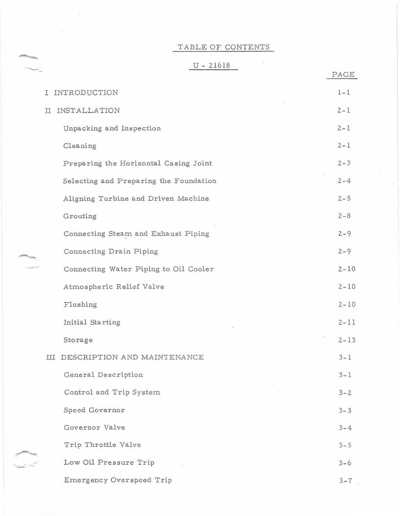
T ABLE OF CONTENTS
U - 21618 PAGE
I INTRODUCTION 1-1
II INSTALLATION
Unpacking and Inspection
Cleaning
Preparing the Horizontal Casing Joint
Selecting and Preparing the Foundation
Aligning Turbine and Driven Machine
Grouting
Connecting Stea~ and Exhaust Piping
. __ Connecting Drain Piping
'~~r""~-- Connecting Water Piping to Oil Cooler
Atmospheric Relief Valve
Flushing
Initial Sta r ti ng
Storage
III DESCRIPTION AND MAINTENANCE
2-1
2.-1
2.-1
2-3
2.-4
2.-5
2-8
2.-9
2.-9
2-10
2-10
2-10
2-11
2.-13
3-1
General Description 3-1
Control and Trip System 3-2
Speed Governor 3- 3
Governor Valve 3-4
Trip Throttle Valve 3-5
Low Oil Pressure Trip 3-6
Emergency Overspeed Trip 3-7

TABLE OF CONTENTS
U - 21618 PAGE
Solenoid Dump Valve 3-8
Axial Movement Detectors 3-9
Vibration Detectors 3- 9. 1
Grounding Brush 3-9.2
Pressure Oil System 3-10
Lubricating Oil 3-10
Main Oil Pump 3-11
Oil Filter 3-11
Oil Cooler 3-11
A uxi.l ia r y Oil Pump 3-12
Shaft Pac king 3-14
Main Bearings 3-15
Thrust Bearing s 3-16
Gland Leakoff System 3-17
Turning Gear 3-18
IV OPERATING INSTRUCTIONS
Starting Procedure 4-1
Shutdown Procedure 4-3
Testing Overspeed Trip 4-4
Operating Precautions 4-5
V RECOMMENDED MAINTENANCE SCHEDULE 5-1
VI TROUBLESHOOTING RECOMMENDED SPARE PAR TS LIST COMMERCIAL PRODUCTS FOR TURBINE SERVICE STEAM PIPING FOR TURBINES W - 96 DRA WINGS AND A UXILIARY EQUIPMENT
6-1
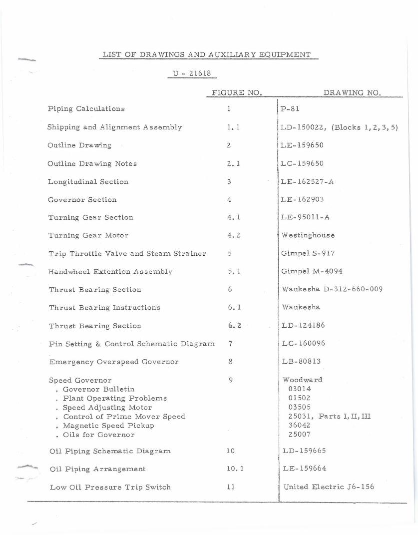
LIST OF DRA WINGS AND A UXILIAR Y EQUIPMENT
U-21618
FIGURE NO. DRAWING NO.
Pi ping Calc ul a t i on s 1 I P-81
Pin Setting & Control Schematic Diagram LC-160096
6
I ,LD-150022. (Blocks 1,2,3,5) Shipping and Alignment As semb1y 1.1
Outline Drawing 2 I LE-159650
Outline Drawing Notes 2. 1 . LC-159650
Longitudinal Section 3 LE-162527-A
Governor Section 4 LE-162903
Turning Gear Section 4. 1 LE-95011-A
Turning Gear Motor 4.2 . Westinghouse
Trip Throttle Valve and Steam Strainer 5 Gimpel S-917 -. Handwheel Extention Assembly 5. 1 Gimpel M-4094
Thrust Bea ring Section Waukesha D-312-660-009
Thrust Bearing Instructions 6. 1 i Waukesha
Thrust Bearing Section 6.2 , LD-124186
7
LB-80813 Emergency Overspeed Governor 8
;1 Woodward ~ 03014
01502 03505 25031, Parts I, II, III 36042 25007
Speed Governor • Governor Bulletin · Plant Operating Problems
Speed Adj usting Motor • Control of Prime Mover Speed • Magnetic Speed Pic kup · Oils for Governor
9
Oil Piping Schematic Diagram 10 LD-159665
11
LE-159664
Low Oil Pressure Trip Switch United Electric J6-156
Oil Piping Arrangement 10. 1

LIST OF DRAWINGS AND AUXILIARY EQUIPMENT
U-216l8
FIGURE NO. DRAWING NO.
Low Oil Level Alarm Switch 11. 1 Sensi-Level 302-11-2-X
Packing Ring Diagram 17 EW-33275
Leakage Diagram 17. 1 LC-159930
Assembly of Labyrinth Packing in Diaframs 18 LC-l49957
Preparing Horizontal Flange 19 D-32618
Coupling 20 Sier Bath F- 5- 1/2
Solenoid Dump Valve 21 ASCO #8211 C88 ,......., •..
3- Way Solenoid Dump Valve 21. 1 ASCO #83l7A15
Low Oil Pressure Alarm Switch 11. 2
Main Oil Pump Worthington #6 12
Oil Filter 13
Differential Pressure Switch Across Filter 13. 1
Oil Cooler 14
Emergency Oil Pump 14.1
Emergency Oil Pump Start Switch 14.2
Turning Gear Permissive Start Switch 14.3
A uxi l ia r y Oil Pump Turbodyne #12 15
Auxiliary Oil Pump Governor 15. 1
Auxiliary Oil Pump Running Switch 15.2
United Electric J6-156 (See Figure 11)
B-28948-A
Duplex 1200-518-1. SF. S.
United Electric J300K- 55~
Basco OP #08072
#2 GRWM
United Electric J6-156 (See Figure ll)
United Electric J6-l56 (See Figure 11)
C-68806-A
Ma s orie i.Ia n #535C
United Electric J6-156 (See Figure 11)

LIST OF DRAWINGS AND A UXILIARY EQUIPMENT
U-2l618
FIGURE NO. DRAWING NO.
Gland Leakoif Piping Diagram 22 I LD-159666
31
LD-159667 Gland Condenser Piping 23
Gland Condenser 24 Basco #08060 Type 500
Gland Condenser Air Ejector 25 Penberthy GH-l LB-153S64
Pressure Reducing Valve 26 Masoneilan #52S(See Fig.IS.:
Back Pressure Regulator 27 Ma sone i.Ia n #S26(See Fig.15.1
Pressure Transmitter 34
Bentl y- Nevada
Wiring Diagram 28 LE-162067
Immersion Heater 29 Chromalox #3305
Tachometer 30 Ai r pax J - Probe Adapter Assembly LC-130625
Probes and Proximitor s 32
Grounding Brush Assembly 33 LB-157095
Nullmatic Indicating Station 36
\I Moore Model 17 3S
'I Moore Model 50M " I Moore Model 524MT2
Nullmatic Controller 35
Outline Diagram-Generator Terminal Box 37 Electric Machinery 385C61 Th1
Schematic Diagram 38 E. M. 384C2.47N
43
E. M. 386C126N
Electrical Connection 39 E. M. 115D719
Connection Diagram 40
Outline - Turbo Generator 41 E. M. 115D720
Generator Instructions 42 Electric Machinery
Ga ug e boa r d Panel DRC #810104