turbo pumping station model 655 - dartmouth college
TRANSCRIPT

Page 1
Copyright © 2015 Gatan Inc. All rights reserved.
Gatan, Inc. 5794 W. Las Positas Blvd. Pleasanton, CA 94588 t +1.925.463.0200 [email protected] www.gatan.com
Turbo Pumping Station Model 655

Turbo Pumping Station Model 655
Copyright 2015 Gatan Inc. All Rights Reserved. All rights reserved. No parts of this work may be reproduced in any form or by any means—graphic, electronic, or mechanical, including photocopying, recording, taping, or information storage and retrieval systems—without the written permission of the publisher.
Products that are referred to in this document may be either trademarks and/or registered trademarks of the respective owners. The publisher and the author make no claim to these trademarks.
While every precaution has been taken in the preparation of this document, the publisher and the author assume no responsibility for errors or omissions, or for damages resulting from the use of information contained in this document or from the use of programs and source code that may accompany it. In no event shall the publisher and the author be liable for any loss of profit or any other commercial damage caused or alleged to have been caused directly or indirectly by this document.
Publisher Gatan Inc.
Technical editors Gatan Holder Team
Document version 655.40001_09
www.gatan.com

Page 3
Turbo Pumping Station Model 655
Table of Contents
1 Operators safety summary ........................................................................................ 5
1.1 General information ................................................................................................................................... 5
1.2 Terms ........................................................................................................................................................ 5
1.3 Symbols .................................................................................................................................................... 5
1.4 Power source ............................................................................................................................................ 6
1.5 Grounding the product ............................................................................................................................... 6
1.6 Danger arising from loss of ground ........................................................................................................... 6
1.7 Use the proper fuse ................................................................................................................................... 6
1.8 Do not operate in explosive atmospheres ................................................................................................. 7
1.9 Do not operate without covers ................................................................................................................... 7
2 Service safety summary ............................................................................................ 8
FOR QUALIFIED SERVICE PERSONNEL ONLY .......................................................................................... 8
2.1 Do not service alone .................................................................................................................................. 8
2.2 Use care when servicing with power on .................................................................................................... 8
2.3 Power source ............................................................................................................................................ 8
3 Introduction ................................................................................................................ 9
3.1 Description ................................................................................................................................................ 9
3.2 Specimen holder module ......................................................................................................................... 12
3.3 Vacuum store module ............................................................................................................................. 14
3.4 Unpacking and assembly ........................................................................................................................ 18
4 Operation .................................................................................................................. 19
4.1 Start-up procedure .................................................................................................................................. 19
4.2 Procedure for evacuating a cold holder dewar ........................................................................................ 20
4.3 Procedure for leak checking a cold holder dewar .................................................................................... 20
4.4 Specimen holder removal ........................................................................................................................ 21

Table of Contents Page 4
Turbo Pumping Station Model 655
4.5 Shut down procedure .............................................................................................................................. 21
5 Maintenance .............................................................................................................. 22
5.1 Servicing the diaphragm pump ................................................................................................................ 23
5.2 Servicing the molecular drag pump ......................................................................................................... 23
5.3 Servicing the cold cathode gauge ........................................................................................................... 23
6 Spares ....................................................................................................................... 26
7 Warranty .................................................................................................................... 27

Page 5
Turbo Pumping Station Model 655
1 Operators safety summary
1.1 General information The general safety information in this part of the summary is for both operating and servicing personnel. Specific warnings and cautions will be found through-out the manual where they apply, but may not appear in this summary.
1.2 Terms In This Manual:
CAUTION statements identify conditions or practices that could result in damage to the equipment or other property.
WARNING statements identify conditions or practices that could result in personal injury or loss of life.
As Marked on Equipment:
CAUTION indicates a personal injury hazard not immediately accessible as one reads the marking, or a hazard to property including the equipment itself.
DANGER indicates a personal injury hazard immediately accessible as one reads the marking.
1.3 Symbols In This Manual:
This symbol indicates where applicable cautionary or other information is to be found.

Operators safety summary Page 6
Turbo Pumping Station Model 655
As Marked on Equipment:
DANGER – High voltage
Protective ground (earth) terminal
ATTENTION – refer to manual
1.4 Power source This product is intended to operate connected to a power source that will not apply more than 250 volts rms between the supply conductors or between either supply conductor and ground. A protective ground connection by way of the grounding conductor in the power cord is essential for safe operation.
1.5 Grounding the product This product is grounded through the grounding conductor of the power module power cord. To avoid electrical shock, plug the power cord into a properly wired receptacle before connecting to the product input or output terminals. A protective ground connection by way of the grounding conductor in the power cord is essential for safe operation.
1.6 Danger arising from loss of ground This product is grounded through the grounding conductor of the power module power cord. To avoid electrical shock, plug the power cord into a properly wired receptacle before connecting to the product input or output terminals. A protective ground connection by way of the grounding conductor in the power cord is essential for safe operation.
1.7 Use the proper fuse To avoid fire hazard, use only the fuse of correct type, voltage rating and current rating as specified in the parts list for your product. Refer fuse replacement to qualified service personnel.

Operators safety summary Page 7
Turbo Pumping Station Model 655
1.8 Do not operate in explosive atmospheres To avoid explosion, do not operate this product in an explosive atmosphere unless it has been specifically certified for such operation.
1.9 Do not operate without covers To avoid personal injury, do not operate this product without covers or panels installed. Do not apply power to this product while making internal changes.

Service safety summary Page 8
Turbo Pumping Station Model 655
2 Service safety summary
FOR QUALIFIED SERVICE PERSONNEL ONLY Refer also to the preceding operator’s safety instructions
2.1 Do not service alone To avoid personal injury, do not operate this product without covers or panels installed. Do not apply power to this product while making internal changes.
2.2 Use care when servicing with power on To avoid personal injury, do not operate this product without covers or panels installed. Do not apply power to this product while making internal changes.
2.3 Power source This product is intended to operate connected to a power source that will not apply more than 250 volts rms between the supply conductors or between either supply conductor and ground. A protective ground connection by way of the grounding conductor in the power cord is essential for safe operation.

Introduction Page 9
Turbo Pumping Station Model 655
3 Introduction
3.1 Description The Model 655 is a completely self-contained, compact, lightweight, bench top pumping station incorporating the latest diaphragm pump and molecular drag pump (MDP) technologies to produce a clean dry vacuum in the 10-6 Torr range. The pumping time from atmosphere to near the base pressure is typically less than 5 minutes, the pressure being monitored by a simple Penning gauge. The turbo pumping station is oil free and will not contaminate the cryosorption pump used in Gatan's closed dewar-type cold holders even when the dewar is filled with liquid nitrogen. The Model 655-0500 module has been designed specifically for evacuating and leak checking specimen holders from all types of TEMs. Tilting and heating operations may be performed and viewed directly through a Pyrex glass work chamber while the specimen is under vacuum. Two large butterfly valves are provided between the pump and the specimen holder module so that it is possible to isolate either the specimen rod or a spare pumping port (normally used for dewar evacuation). The Model 655.11000 Vacuum Store Module has been developed to offer storage of 3 millimeter samples in the 655. Each module contains two storage capsules that hold six samples each. A third capsule (655.11300) can be added to increase the total number of samples from the standard 12 to 18 per module. The storage capsules incorporate a removable 6 grid array that makes it convenient to transfer samples between the 655 and the TEM or specimen preparation equipment. The Model 655 operates on less than 300 watts and accepts universal input voltage between 100 to 240VAC. The station is designed for simplicity and ease of operation, the diaphragm pump, the molecular drag pump (MDP) and the Penning gauge all being controlled by a single ON/OFF switch mounted at the rear panel. In addition to the switch there is a Penning gauge meter and four colored indicator lights to show the operating mode of the MDP. Upon startup the yellow indicator will light; once the MDP reaches the normal running speed without any errors, two green LEDs will light at the right. Yellow LED indicates power is ON to the controller. Red LED indicates a pump shut down due to an overload or time out failure. Green LED indicates the MDP has no errors. Green LED indicates the MDP has reached > 80% of its normal running speed. The rear panel of the instrument houses a fused connector for the power cord along with the ON/OFF power switch and the cabinet cooling fan. The MDP inside the cabinet has a pumping speed of 60 liters/sec at an ultimate pressure of about 1 x 10⁻⁶ Torr. This characteristic enables the pump to be backed by an oil-free diaphragm pump thus producing a clean, compact vacuum system with minimum power consumption. The diaphragm pump used in the Model 655 was chosen for its low vibration, low maintenance and easy start-up characteristics.

Introduction Page 10
Turbo Pumping Station Model 655
A three way solenoid valve operates to seal off and maintain the specimen holder module and the MDP under vacuum when power is switched OFF. The same valve also vents the diaphragm pump so that the system may be restarted easily under vacuum thus allowing the ultimate vacuum to be achieved within a matter of minutes.
Figure 1: Model 655 Turbo Pumping Station with holder
V3
Model 655 Workstation with TEM Holder Module
Dewar evacuation valve

Introduction Page 11
Turbo Pumping Station Model 655
Figure 2: Model 655 Turbo Pumping Station wiring diagram

Introduction Page 12
Turbo Pumping Station Model 655
3.2 Specimen holder module The Model 655.05 specimen holder module (TEM Module) is an attachment to the Model 655 turbo pumping station and is used for evacuating and checking the operation of TEM specimen holders. When placed in the module the specimen holder protrudes into a Pyrex glass tube so that the specimen region can be viewed closely while under vacuum. The specimen rod can be isolated from the vacuum station by closing butterfly valve V1. The Penning gauge is placed between this valve and a second butterfly valve V2 which isolates the vacuum station from the dewar evacuation port. In this location the Penning gauge is useful for simple leak checking procedures. The specimen holder module is an invaluable tool for diagnosing faults in the more complicated types of specimen holder. Typical applications include:
a. Checking the shutter mechanism of the Model 626 and 915 cryotransfer holders.
b. Evacuating dewars on Model 613, 626, 636, 671, 910 and 915 cold holders.
c. Leak checking specimen holders and specimen holder dewars.
d. Testing cooling and heating rates of hot and cold stages.
e. Observing the deformation behavior of specimens in Model 654 and 671 straining stages.
f. Observing the tilt behavior of Model 636, 646, 648, 652, 915 and 925 holders.
g. Evacuating helium transfer lines.
h. Checking the operation of indexed Model 677 and 910 multiple specimen holders.
The module can be expanded to accept up to four specimen rods. The optional expansion kits (655.05400) can be chosen to suit any combination of side entry specimen holder types. This feature is particularly useful in laboratories having several different types of microscopes each having cold holders that require periodic evacuation.

Introduction Page 13
Turbo Pumping Station Model 655
Figure 3: Vacuum stack
COLD CATHODE GAUGE 695.03550

Introduction Page 14
Turbo Pumping Station Model 655
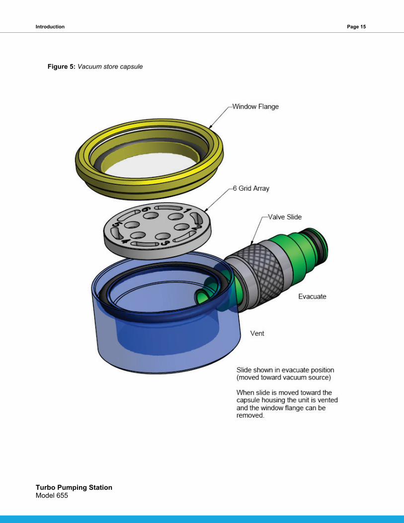
3.3 Vacuum store module The 655.11000 Vacuum Store Module shown in figure 4 holds 12 specimens under vacuum in the 655. This module is included when the 655 is ordered for storage only. Six specimens are stored in each specimen capsule 655.11300 (see figure 5). The specimens can be viewed through a Pyrex window that is mounted in a removable flange. The 6 grid arrays can be marked for identification using a pen such as (Ted Pella #27175) or equivalent. The capsule has a sliding valve that when moved toward the vacuum source evacuates the 6 grid array. Moving the slide toward the storage capsule housing shuts off vacuum from the stack and vents the capsule. This top module and other storage modules can be combined with TEM modules for a system that can evacuate a combination of specimens and TEM holders. A butterfly valve 655.11200 can be placed anywhere in the vacuum stack to isolate either Vacuum Store Modules or TEM Modules. Placing the butterfly valve above the TEM Modules to separate the holders from the Vacuum Store Modules makes it possible to keep the stored specimens under vacuum while removing a holder. This valve can also be used to segregate long term storage items from more active ones. The long term items just need to be located above the position of the valve. Possible configurations for storage only systems and combination storage and TEM systems are shown in figures 6 and 7.
The storage capsules are held into the module housing by socket set screws. To remove a capsule the retaining screw simply needs to be loosened and the capsule pulled out of the housing. A third capsule can be added to any Vacuum Store housing by removing the blanking plug. The blanking plug is also held into the housing with a set screw.
Figure 4: Vacuum store module
Introduction Page 15
Turbo Pumping Station Model 655
Figure 5: Vacuum store capsule

Introduction Page 16
Turbo Pumping Station Model 655
Figure 6: 655 Storage only system with second vacuum store module

Introduction Page 17
Turbo Pumping Station Model 655
Figure 7: 655 Combination TEM and specimen storage system

Introduction Page 18
Turbo Pumping Station Model 655
3.4 Unpacking and assembly The packing list contained with the Turbo Pumping Station must first be checked to verify your order and also to note if there is any discrepancy between the list and what has been received. The turbo pumping station is shipped disassembled (four basic parts) to reduce the risk of damage to the specimen holder module. Additionally, for shipping purposes only, the diaphragm pump is securely held in place with a locking screw which must be removed prior to starting the pumping station. Remove the locking screw by allowing the left side of the station to overhang the edge of the bench slightly, then reaching under the base remove the locking screw. Once removed, the screw should be stored in the position indicated, on the bottom, to allow it to be used again in the event the station must be returned to the factory for repair. Assembly is relatively easy and is started by removing the plastic dust covers, one from the top of the molecular drag pump (MDP) and one from the bottom of the specimen holder module. Place the inlet screen and O-ring on the MDP (making sure the surfaces are clean) and mount the specimen holder module. The orientation of the Pyrex viewing tube should be on your left when facing the front of the pumping station. Insert the two screws into the flange and lightly tighten. These screws need only be snug since they fit into a groove in the flange of the MDP thus preventing the specimen holder module from lifting off. Next remove the dust caps from the Penning gauge tube and the gauge port at the rear of the specimen holder module, insert the gauge tube and connect the cable coming from the rear panel of the pumping station. Plug the power cord into the instrument connector on the rear panel and plug the other end into the mains supply. The turbo pumping station is now ready to turn ON.
Should expansion kits have been ordered they are installed on top of each other between the butterfly valve manifold and the standard chamber (see figure 3). If it is required to evacuate more than 2 dewars simultaneously a second valve assembly (655.05300) should be installed in place of the blanking plug shown in figure 3.

Operation Page 19
Turbo Pumping Station Model 655
4 Operation
The following procedure assumes that a single specimen holder module has been installed.
Caution: when the turbo pump is operating and atmosphere exists in the workstation and any TEM or specimen storage modules, the recommended practice to open any of the butterfly valves (V1, V2 or an extra valve installed above the workstation) is to actuate them slowly to avoid dumping a large volume of atmosphere into the turbo pump. These valves are opened by rotating them in a counter clockwise direction starting from a horizontal closed position to a vertical open position. This rotation should be performed using an interval of between 10 to 15 seconds. If a pump failure condition should happen to occur while operating any of these valves, it can be cleared by using the power switch at the rear of the unit. Turn this switch off and wait for 30 seconds and then restart the unit.
A large volume of atmosphere dumped into the system can cause the cold cathode gauge to go into an error mode. The gauge does this as a protective measure to keep its internal components from being damaged. The error mode is indicated by a solid yellow led on the back of the gauge and the meter on the front panel will be pegged completely off scale to the left. Note that the vacuum pumps will continue to run. The cold cathode gauge can be reset by turning off the main power switch and turning it back on after five seconds.
4.1 Start-up procedure 1. Close UPPER butterfly valve V1 (turn knob to the horizontal position, as shown in figure 3) and open LOWER valve V2.
2. Close the dewar evacuation valve, V3 (turn fully clockwise).
3. Insert a specimen holder (or blanking plug) into the specimen rod adaptor assembly.
4. Turn ON the main power switch located on the rear panel. The diaphragm pump will start and the sound from the MDP will be heard to increase in pitch. When the MDP reaches > 80% of its normal operating speed the second green LED on the front panel will light.
5. The vacuum reading observed on the Penning gauge meter should decrease quickly to the 10-5 Torr range.
6. If the second green LED is lit, the UPPER butterfly valve V1 can be opened (rotate knob CCW until it points straight up) to evacuate the specimen holder chamber. If the system is leak tight the pressure will slowly decrease to the 10-6 Torr range.

Operation Page 20
Turbo Pumping Station Model 655
4.2 Procedure for evacuating a cold holder dewar 1. Close V1 and remove the blanking plug to vent the specimen chamber (see figure 1).
2. Slide the cold holder fully into the specimen holder adaptor. (The adaptor must be the correct type for the holder).
3. Take the plastic hose attached to pumping port No.1 and connect it to the valve on the dewar. Check that the other plastic hose attached to pumping port No.2 is secured on the rear blanking post.
4. Open V1 to evacuate the specimen holder chamber and wait for the vacuum reading to reach the 10-5 Torr range.
5. Open V3 (turn fully clockwise- a partially open valve will severely reduce the pumping speed).
6. When the pressure reaches the 10-5 Torr range open the valve on the dewar (turn the valve fully counterclockwise but do not pull it out as this will vent the dewar).
7. Connect the Model 900 SmartSet Cold Stage Controller or Model 1905 Temperature Controller to the dewar. Pump on the dewar while running the Bakeout Cycle for at least two hours to regenerate the cryosorption pump.
6. Close the dewar evacuation valve until finger tight, then switch off the heater and disconnect the heater cable.
4.3 Procedure for leak checking a cold holder dewar 1. Close V1 and remove the blanking plug to vent the specimen chamber.
2. Slide the cold holder fully into the specimen holder adaptor. (The adaptor must be the correct type for the holder).
3. Take the plastic hose attached to pumping port No.1 and connect it to the valve on the dewar. Check that the other plastic hose attached to pumping port No.2 is secured on the rear blanking post.
4. Open V1 to evacuate the specimen holder chamber and wait for the vacuum reading to reach the 10-5 Torr range.
5. Open V3 (turn fully clockwise- a partially open valve will severely reduce the pumping speed).
6. When the pressure reaches the 10-5 Torr range open the valve on the dewar (turn the valve fully counterclockwise but do not pull it out as this will vent the dewar).
7. Connect the Model 900 SmartSet Cold Stage Controller or Model 1905 Temperature Controller to the dewar. Pump on the dewar while running the Bakeout Cycle for at least two hours to regenerate the cryosorption pump.
6. Close the dewar evacuation valve until finger tight, then switch off the heater and disconnect the heater cable.

Operation Page 21
Turbo Pumping Station Model 655
4.4 Specimen holder removal The specimen holder can be pulled out of the adaptor at any time after first closing the upper butterfly valve V1 and the appropriate dewar evacuation valve V3. If the holder is going to be removed for some time it is advisable to replace it with a blanking plug and then to re-evacuate the chamber. This will reduce the amount of water vapor that is adsorbed onto the chamber walls and hence shorten the subsequent pump down time when the holder is re-inserted.
4.5 Shut down procedure The procedure is to insert a specimen holder or blanking plug into the adaptor and then to evacuate the module. The pumping station is then switched OFF. The vacuum will remain in the station and the station may be restarted at any time while still under vacuum.

Maintenance Page 22
Turbo Pumping Station Model 655
5 Maintenance
Due to the simple design of the turbo pumping station only three items require periodic servicing. Maintenance must be performed on both the diaphragm pump and the MDP at the prescribed intervals in order for the pumping station to maintain its low base pressure and high pumping speed. This will require removal and disassembly of the pump or pumps at the time of service. The third item, the Penning gauge tube, may be removed and serviced with the pumps operating and under vacuum.
Service item Interval Maintenance Symptom Replacement
Diaphragm pump Variable Replace diaphragms Poor base pressure Kit #10546
MDP Once per year Replace oil cartridge N/A #05577
Gauge tube Variable Rebuild Erratic reading
Servicing of any component inside the pumping station console requires venting the vacuum system to atmosphere, removing the complete specimen holder module from the MDP and removing the console cover.
a. Turn OFF mains switch located on the back of the unit.
b. Unplug the line cord from the rear of the pumping station.
c. Disconnect the coaxial cable from the Penning gauge tube.
d. Vent the specimen holder module to atmosphere.
e. Loosen the two red thumbscrews around the base of the specimen holder module and lift it from the MDP.
f. Remove the 8 screws holding the cover to the base, 2 on each side, and 4 on top, and lift off the cover.
g. Place the shipping cap on the MDP or cover it with aluminum foil to hold the inlet screen in place and prevent the entry of dust.

Maintenance Page 23
Turbo Pumping Station Model 655
5.1 Servicing the diaphragm pump In order to service the diaphragm pump, it must first be removed from the cabinet. Remove the diaphragm pump from the pumping station by: (1) Unscrew the fastener that retains the small connector that supplies power to the pump and unplug the connector. (2) Disconnect the vacuum hose running from the diaphragm pump to the MDP by pulling the hose off of the fitting on the pump. (3) Undo the two slide latch fasteners that hold the pump in place and lift out the pump. Please refer to the “Maintenance” section of the Pfeiffer manual for complete details for replacing the diaphragms. Once fully assembled, the pump assembly can be placed back into the cabinet. (1) Position the pump over the latching studs and secure it by locking the slide fasteners. (2) Connect the vacuum hose pushing it back onto the pump fitting. (3) Plug in the electrical cable and tighten the screw that retains the connector.
5.2 Servicing the molecular drag pump The MDP is lubricated at the factory prior to shipping but must be re-lubricated approximately once a year. In order to service the pump, it must first be removed from the cabinet. Before removing the MDP from the pumping station make sure the inlet flange is protected with the plastic shipping cap or aluminum foil. (1) Unplug the electrical connector from the box on the side of the pump. The connector latch protrudes beyond one side of the connector shell. Slide the protruding side toward the shell and pull up on the connector. (2) Disconnect the vacuum hose by undoing the KF clamp at the port on the side of the MDP. Cover the port with aluminum foil to keep dust from entering the pump. (3) Disconnect the ground strap at the cabinet base. (4) Remove the four red thumbscrews to remove the MDP. Please refer to the “Maintenance” section of the Pfeiffer manual for complete details for replacing the oil cartridge. Once fully assembled, the pump assembly can be placed back into the cabinet. (1) Remount the pump installing the four thumbscrews. (2) Attach the ground strap to the cabinet base. (3) Attach the vacuum hose by reconnecting the KF fitting. (4) Attach the electrical cable to the MDP electrical connector. Slide the connector latch to retain the connector.
5.3 Servicing the cold cathode gauge Contamination of the measuring chamber within the tube will affect the pressure reading and generally produce an indication that the pressure is too low. If contamination becomes severe, instability may occur resulting in shorts that may cause the needle on the penning meter to jump to the right end of the scale. If this occurs the gauge tube must be dismantled and rebuilt.
Remove the gauge head as follows:
a. Close V2 the lower butterfly valve and vent the specimen holder module thru the pumping port.
b. Disconnect the cable from the gauge tube by first unscrewing the retaining screw at the center of the connector.
c. Pull the gauge tube straight out of its vacuum port.

Maintenance Page 24
Turbo Pumping Station Model 655
Figure 8: Cold cathode gauge
Disassemble the gauge head as follows:
a. Unfasten the hexagon socket set screw (4) and carefully remove the complete measuring chamber (3) from the electronics unit (5).
b. Remove the retaining ring (1) as well as the ionization chamber (2) from the measuring chamber (3). c. Check the ionization chamber and the measuring chamber for contamination:
1. Ionization chamber is contaminated only: Replace the ionization chamber. 2. Measuring chamber is severely contaminated: Try cleaning or replace the gauge.
Using an ohmmeter, make the following measurements on the contact pins.

Maintenance Page 25
Turbo Pumping Station Model 655
Figure 9: Replacing a new ionization chamber and ignition aid
a. Remove the ignition aid with the removing tool. b. Rub the inside walls of the measuring chamber (3) up to the groove for the retaining ring to a bright finish
using a polishing cloth.
The sealing surfaces must only be worked concentrically.
Do not bend the anode.
c. Insert the new ignition aid into the mounting tool and slide it onto the anode. d. Slide a new ionization chamber (2) into the measuring chamber (3) until the mechanical stop is reached
and mount the retaining ring (1).
Reverse the disassembly steps to reassemble the gauge. Be very careful not to bend the contact pins when inserting the measuring chamber into the electronics unit.
Replace the gauge tube into its port and reconnect the cable. Start-up the pumping system if necessary and open V2. If the pressure does not improve, contact your local Gatan office.

Spares Page 26
Turbo Pumping Station Model 655
6 Spares
695.03550 TUBE, IKR 360 GAUGE
104115 TOOL, IGNITION AID FOR IKR 360
104116 IONIZATION CHAMBER FOR IKR 360

Warranty Page 27
Turbo Pumping Station Model 655
7 Warranty
Gatan products are warranted per the terms and conditions outlined in the product warranty. Contact Gatan customer service at http://www.gatan.com/support .