turbocharger installation guide - ctiturbo.comctiturbo.com/installation-guide.pdf · turbocharger...
TRANSCRIPT

TurbochargerInstallation Guide
3214 Producer Way Unit A Pomona, CA 91768 Phone: 909-594-8400 Email: [email protected]
Comp TurboTechnology Inc.

Thank You For Choosing Comp Turbo. We strive to
provide the highest level of customer service and high quality
performance turbochargers. We hope that your experience
with us was pleasant, and that we can be a part of any future
projects. As a valued customer, your comments and opinions
are very important to us. If you have any concerns, questions,
or comments, we hope that you will bring them to our attention.
If you have any technical questions during installation our
experienced technical support team is available to assist.
Sincerely,
Team Comp Turbo
Table of Contents
A Guide to successful turbocharging ............................................. Page 4
Matching a Turbocharger to an Engine ........................................... Page 5
Comp Turbo Compressors ................................................................... Page 6
Comp Turbo Turbines .............................................................................Page 7
Installation of a Turbo on a Engine.................................................. Page 8
Oil Drain and Water Port Sizes ..........................................................Page 11
Turbocharger Installation guide ....................................................Page 12
Turbocharger Installation Guide Oil-Less 2.0 ..............................Page 13
Warranty ................................................................................................Page 14
Contact Info ...........................................................................................Page 15

Fig. 1
A TYPICAL TURBOCHARGER CROSS SECTION
4
GENERAL DESCRIPTIONThe Comp Turbo Technology turbochargers are advanced state of the art exhaust gas turbine-driven centrifugal compressors. (See Fig. 1) Their purpose is to increase the amount of air delivered to internal combustion engine cylinders above the amount available through natural aspiration. This increased amount of air allows the engine to burn more fuel and, in turn, produce more power.
The turbocharger consists of thee main components; the compressor, the turbine and the bearing system. The turbine utilizes the energy in the engine exhaust gas which enters the turbine casing through the flange connected to the exhaust manifold. The exhaust gas enters the turbine wheel at high pressure around its periphery and expands to the atmosphere through the turbine wheel gas passages.
This expansion causes the turbine wheel to rotate and converts exhaust gas energy into mechanical work which drives the compressor wheel mounted on the same shaft.
Air is induced into the compressor wheel by virtue of its rotation and flows radially outward through a diffuser section prior to entering the compressor casing. The compressed air leaves the compressor casing through a tangential outlet connected to the engine intake manifold or connected to an after-cooler that removes much of the heat of compression before the air enters the engine air intake manifold.
The rotating assembly, consisting of the turbine wheel and compressor wheels mounted on the same shaft, is contained within a bearing housing and can be supported by several different bearing systems. The full floating type sleeve bearing system and a triple ball bearing system are lubricated by engine oil. A third type is a ball bearing system that is lubricated by high-temperature grease and needs no oil from the engine. Small piston rings are used to seal off both the compressor casing and turbine casing from direct communication with the interior of the bearing housing.
A GUIDE TO SUCCESSFUL TURBOCHARGING

5
MATCHING THE TURBOCHARGER TO THE ENGINEThe process of matching the characteristics of a turbocharger to an internal combustion engine begins by calculating an estimated pressure ratio and airflow required at the full power and speed rating of the engine. A calculation method is available from Comp Turbo Technology in the form of an easily followed step-by-step method outlined on a calculation sheet.
Once the required compressor pressure ratio and compressor inlet airflow have been estimated, this data is entered on an appropriate compressor performance map. In making the preliminary determination of the proper compressor size, consideration must be given to the required engine torque curve, the engine speed range, the possibility of operation at high altitude and if an after-cooler is to be used. All of these factors influence the manner in which the engine air requirement is positioned on the compressor performance map. Consideration must be given to providing adequate margin away from the surge and choke areas (See Fig. 2).
Fig. 2
TYPICAL COMPRESSOR PERFORMANCE MAP WITH ENGINE AIRFLOW SUPERIMPOSED

Fig. 3Compressor Wheel
Fig. 4Volute Compressor Casing
6
COMP TURBO COMPRESSORS
Typical Comp turbo compressor wheels are 5-axis machined from an aluminum billet that has significantly higher mechanical properties than cast wheels and are thus capable of higher speed and pressure ratios. Aerodynamically, they represent the latest in compressor design technology that includes backward leaning, alternately cut back vanes. The inducer diameters are maximized so that high air mass flow is obtained from small diameter wheels (see Fig. 3). Vaneless diffusers and volute compressor casings are used, resulting in a compact design with broad range and high efficiency (See Fig. 4).
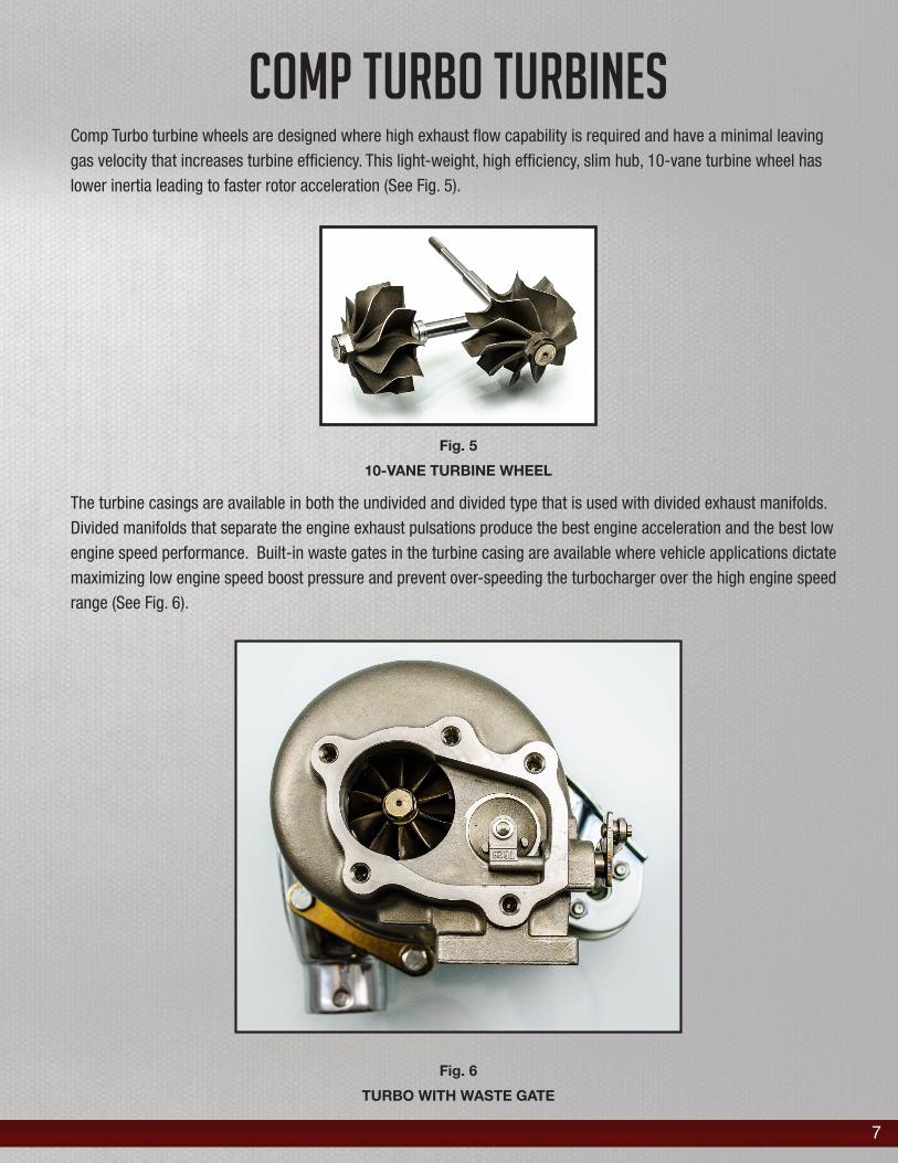
Fig. 5
10-VANE TURBINE WHEEL
7
COMP TURBO TURBINESComp Turbo turbine wheels are designed where high exhaust flow capability is required and have a minimal leaving gas velocity that increases turbine efficiency. This light-weight, high efficiency, slim hub, 10-vane turbine wheel has lower inertia leading to faster rotor acceleration (See Fig. 5).
The turbine casings are available in both the undivided and divided type that is used with divided exhaust manifolds. Divided manifolds that separate the engine exhaust pulsations produce the best engine acceleration and the best low engine speed performance. Built-in waste gates in the turbine casing are available where vehicle applications dictate maximizing low engine speed boost pressure and prevent over-speeding the turbocharger over the high engine speed range (See Fig. 6).
Fig. 6
TURBO WITH WASTE GATE

8
INSTALLATION OF THE TURBOCHARGER ON THE ENGINE
Satisfactory performance and service life of turbochargers depends to a large extent on proper installation of the turbocharger on the engine.
MOUNTING
Comp Turbo turbochargers with their aluminum bearing housings are small and light enough to be mounted solidly on the exhaust manifold. The exhaust manifold must be strong enough and adequately bolted to the engine to prevent excessive vibration and maintain good gasket seals. The mounting between the turbine inlet flange and the exhaust manifold flange should be the only rigid connection to the turbocharger. All other piping must be sufficiently flexible so that no loads due to thermal expansion or weight of piping are applied to the turbocharger.
AIR PIPING
The piping between the air cleaner and turbocharger should be the same diameter as the compressor casing air inlet. Air cleaners must be serviced regularly so that the restriction to airflow does not become excessive. Excessive air cleaner restriction can seriously reduce the engine air supply and lead to an increase in exhaust gas temperature . When clean, the air cleaner pressure drop should not exceed 10” of water.
The piping from the turbocharger compressor outlet will usually lead to an after-cooler and should be the same diameter as the compressor outlet.
EXHAUST OUTLET PIPING
The exhaust piping from the turbine casing should be the same size or larger than the outlet flange on the turbine casing. Turbochargers have a significant muffling effect on the engine and, in some cases, a muffler will not be necessary. If a muffler is used, it should be large enough to keep the back pressure on the engine below 1.5” of mercury.
LUBE OIL PIPING
It is important to have a minimum of 35 psi oil pressure at the turbocharger bearings when the oil is up to temperature and the turbocharger is operating at high speeds. The oil inlet piping should be as short as possible to minimize oil pressure lag on engine startup; especially in cold weather. The oil inlet piping should have an inside diameter of at least 3/8”, not have restrictive fittings, and be connected as close to the oil pump as possible. Adequate oil filtering is also essential.
The oil leaving the turbocharger will be in a somewhat foamy condition after passing through the turbocharger bearings. Accordingly, it is necessary to provide a relatively large oil drain line. An inside diameter of 3/4” minimum is recommended. The oil drain line should slope downward over its entire length and be connected to the crankcase above the oil level.
9
GASKETS AND CONNECTIONS
If there are any leaks in the exhaust manifold system or in the air intake system, the engine will not receive the proper amount of air because the turbocharger might not be operating at full speed. A reduced air supply will lead to an increase in exhaust gas temperature.
Exhaust manifold gaskets are somewhat difficult to maintain, but an embossed stainless steel, sheet metal gasket .015” thick, has been found to be satisfactory between the exhaust manifold and turbine casing inlet flanges. Stainless steel studs, nuts and cap screws with good high temperature strengths help maintain satisfactory gasket clamping pressure and prevent leaks from developing in the exhaust system.
FACTORS AFFECTING TURBOCHARGER SERVICE LIFE
Cleanliness of air intake air piping, intake oil pipes and exhaust manifolds is essential. After-coolers should be carefully inspected and blown clean with high pressure air before being installed on the engine. Any foreign material in any of the piping can cause significant damage to the turbocharger compressor and turbine wheels.
The turbocharger bearings should be pre-oiled before the initial installation on the engine. The Comp Turbo oil-less models use grease-lubricated ball bearings and pre-oiling is unnecessary with these models.
A pressure tap should be provided in the air intake manifold and boost pressure should be monitored with a pressure gauge. Observation of boost pressure during engine operation is a convenient means of assessing if the turbocharger is operating properly.
During storage prior to installation on the engine, the turbocharger should be kept covered so that dirt or foreign material cannot enter any of the openings in the compressor casing, turbine casing, or lube oil passages.
The only maintenance required for the turbocharger is an easily accomplished cleaning, dictated primarily by how and where the engine is used. Very dirty operating environments will require more frequent cleaning, however, some types of usage will require no cleaning at all during the entire service life of the unit. It is recommended that, when the engine is to be disassembled for major overhaul, that the turbochargers be disassembled also, inspected and cleaned. The service life of the turbocharger is indefinite as long as it is supplied with an adequate amount of clean lube oil and no foreign material has damaged either the compressor wheel or the turbine wheel.
COMP TURBO OIL-LESS TURBOCHARGERS
Comp Turbo Technology has developed what is believed to be the first commercial turbocharger that does not require a lube oil supply from the engine. The bearing system used in the oil-less models consists of high temperature, grease-lubricated ceramic ball bearings that allow rapid rotor acceleration and have very high mechanical efficiency. Lube oil supply and drain lines are no longer necessary, and the oil-less models can be mounted in a variety of positions and locations that were not possible when lube oil had to be gravity drained back into the engine crankcase.
Problems with lube oil, such as those associated with hot engine shutdown, oil lag in cold weather and oil leakage, are all eliminated when lube oil is no longer used as a bearing system lubricant.

10
The oil-less turbochargers have a cooling jacket in the bearing housing that can be supplied either with engine coolant or cooling air that serves to keep the bearing system operating temperature reasonable at all operating speeds.
SERVICEABILITY OF COMP TURBO TURBOCHARGERS
An important feature of all Comp Turbo turbochargers is their ease of serviceability. They can be easily disassembled for inspection and cleaning. The Triplex-Ceramic™ ball bearings are mounted in a cylindrical cartridge that rotates during operation and is inserted into the bearing housing with a clearance on its outside diameter. Thus, the bearing carrier is easily removed or inserted when the turbocharger is disassembled or re-assembled after servicing. The turbine casing itself need not be removed from the exhaust manifold during a normal inspection of the turbocharger.
Since all parts of Comp Turbo turbochargers are interchangeable, any necessary replacement is a simple matter from stock. The grease-lubricated oil-less models should be inspected between one year and one year and a half of service life. At that time, the ball bearings can be cleaned and re-greased for continued service on the engine.
SUMMARY AND RECOMMENDATIONS
Proper instructions, such as those given in this write-up, should be furnished to the end user so that installation and maintenance procedures are well known and followed. Usually, the normal instructions that apply to any internal combustion engine, including servicing of air cleaners, oil filters and oil change intervals, are available from the engine manufacturer.
In the case of a turbocharged engine, the end user should be cautioned against over-fueling of the engine since the turbocharged version reacts much differently than a naturally aspirated engine if it is over-fueled. Increasing the fuel in a turbocharged engine over that specified for the rated horsepower will cause the turbocharger to run faster, delivering more air to the engine, which in turn will burn the added quantity of fuel producing more power, Continuing this process indiscriminately can result in some sort of destruction or failure due to excessive pressures, temperatures, or excessive turbocharger rotating speed.
Comp Turbo Technology, Inc. has had over ten years of experience in the matching of turbochargers to diesel and gasoline engines. Comp Turbo oiled and oil-less turbochargers have established an enviable record in the field in meeting customer requirements, in providing excellent performance and indefinitely long service life. Technical help in the application of turbochargers is available if needed and ongoing cooperation with customers is a major goal of the company.

11
Triplex Ceramic Ball Bearing Oil Only Aluminum Center SectionTurbo Models Oil Feed Oil Drain Oil Feed Line Oil Drain Fitting
CT2X 1/8 NPT 1/2 NPT -3 1/2 to -10CT3X 1/8 NPT 1/2 NPT -3 1/2 to -10CT4X 1/8 NPT 1/2 NPT -3 1/2 to -10CT43X 1/8 NPT 1/2 NPT -3 1/2 to -10Restrictor required for applications exceeding 50 PSI of Oil Pressure Part # 950039
Required Hardware for Installation
Triplex Ceramic Oil-Less 2.0Turbo Models Water Ports Grease Gun Size Water Line
CT2X 3/8 NPT (In/Out) 3 Oz -6CT3X 3/8 NPT (In/Out) 3 Oz -6CT4X 3/8 NPT (In/Out) 3 Oz -6
CT43X 3/8 NPT (In/Out) 3 Oz -6CT43XR 3/8 NPT (In/Out) 3 Oz -6
CT5X 3/8 NPT (In/Out) 3 Oz -6CT6X 3/8 NPT (In/Out) 3 Oz -6
Required for maintenance Comp Turbo Grease Part # 950000
Triplex Ceramic Ball Bearing Oil Only Aluminum Center SectionTurbo Models Oil Feed Oil Drain Oil Feed Line Oil Drain Fitting
CT43XR 1/8 NPT 3/4 NPT -3 3/4 to -12CT5X 1/8 NPT 3/4 NPT -3 3/4 to -12CT6X 1/8 NPT 3/4 NPT -3 3/4 to -12Restrictor required for applications exceeding 50 PSI of Oil Pressure Part # 950039
360 Dynamic Journal BearingTurbo Models Oil Feed Oil Drain Oil Feed Line Oil Drain Fitting
CT2S 1/8 NPT T3/T4 Flange -4 1/2 NPT to -10CT3S 1/8 NPT T3/T4 Flange -4 1/2 NPT to -10CT4S 1/8 NPT T3/T4 Flange -4 1/2 NPT to -10CT43S 1/8 NPT T3/T4 Flange -4 1/2 NPT to -10Bearing Housing Drain Flange Thread Size 8 mm x 1.25 Pitch
Restrictor required for applications exceeding 75 PSI of Oil Pressure Part # 950040

12
Turbocharger Installation GuideFailure to follow instructions will void warranty
1. Bolt the turbine casing solidly to the exhaust manifold. The connection
from the compressor casing to the air intake piping should be flexible.
2. The oil inlet piping should be short to minimize oil lag on startup and
should be the following size,
• CT3B Ball Bearing should use -3 Oil line.
CT360 Sleeve bearing should use -4 Oil line.
3. The oil drain should be short, slope downward over its entire length and
have at least a ¾" inside diameter. Horizontal runs should be avoided.
4. The turbocharger must be supplied with filtered engine oil at between
35 and 50 psi pressure (CT3B Only) when the oil is up to temperature.
Excessively high oil inlet pressure can cause oil leakage and smoke in the
engine exhaust.
5. Air cleaner pressure drop should be no greater that 10" H2O and muffler
restriction no greater than 1.5" Hg. If no air cleaner is used, a screen
should be placed over the compressor casing air inlet to prevent entry of
foreign material that can damage the compressor wheel.
6. All connections and flanged joints should be checked for leakage when
the engine is running and engine oil and water are warm.
Please contact our Technical Support at 909-594-8400 or Email us at [email protected] for any questions or more information.

13
Turbocharger Installation Guide Oil-Less 2.0
Failure to follow instructions will void warranty
1. Bolt the turbine casing solidly to the exhaust manifold. The connection
from the compressor casing to the air intake piping should be flexible.
2. Since this turbocharger does not require lube oil from the engine, it can
be mounted in a variety of positions, including vertical.
3. This turbocharger contains a water jacket in its bearing housing and must
be supplied with cooling fluid from the engine cooling system.
4. Air cleaner pressure drop should be no greater than 10” H2O and muffler
restriction no greater than 1.5” Hg. If no air cleaner is used, a screen
should be placed over the compressor casing air inlet to prevent entry of
foreign material that can damage the compressor wheel.
5. All connections and flanged joints should be checked for leakage when
the engine is running and the cooling fluid is warm.
6. Apply 2 to 3 pumps of Comp Turbo Grease (Part # 950000) every 3000
miles.
Please contact our Technical Support at 909-594-8400 or Email us at [email protected] for any questions or more information.

14
1 Year Unlimited Mileage WarrantyProducts & Services
Comp Turbo Technology, Inc. Warrants all turbochargers to be free from defects in material
and workmanship for a period of 1 (one) year from the original date of purchase. If we
confirm a defect in a turbocharger covered by this warranty, we will repair at our option with
remanufactured components. There are no refunds on any installed parts and labor, regardless
of fault or reason.
Exclusions
This warranty covers defects in material or workmanship discovered while using the product
as recommended by the manufacturer. The warranty does not cover damage or contingent
damage caused by misuse, abuse, or any modification. The warranty does not cover parts that
are subject to normal wear and tear.
Limits of Liability
If any defects in material or workmanship are found, your sole recourse shall be repair, as
described in the preceding paragraphs. Comp Turbo Technology, Inc. will not be held liable
to your or any other party for any damages that result from the use of this product. Damages
that are excluded, but are not limited to, the following: installation fees, damage to engine
components, damage to personal or public property, personal injury, medical bills, and/or
subsequent death. In no event will Comp Turbo Technology, Inc. will be liable for more than the
turbocharger purchase price, not to exceed the current list price of the product and excluding
tax, shipping and handling charges.
By installation and use of the product, the user accepts all terms described herein.

15
Contact Info
Comp Turbo Technology Inc.3214 Producer Way Unit A Pomona, CA 91768
Phone: 909-594-8400Fax: 909-594-6400
Email: [email protected]@compturbo.com
