turbocharging to extend hcci operating range in a multi cylinder engine- benefits and limitations
DESCRIPTION
Turbocharging to extend HCCI Operating Range in a Multi Cylinder Engine- Benefitsand LimitationsTRANSCRIPT

LUND UNIVERSITY
PO Box 117221 00 Lund+46 46-222 00 00
Turbocharging to extend HCCI Operating Range in a Multi Cylinder Engine- Benefitsand LimitationsJohansson, Thomas; Johansson, Bengt; Tunestål, Per; Aulin, Hans
Published in:[Host publication title missing]
Published: 2010-01-01
Link to publication
Citation for published version (APA):Johansson, T., Johansson, B., Tunestål, P., & Aulin, H. (2010). Turbocharging to extend HCCI Operating Rangein a Multi Cylinder Engine- Benefits and Limitations. In [Host publication title missing]. (pp. 1-14). FISITA.
General rightsCopyright and moral rights for the publications made accessible in the public portal are retained by the authorsand/or other copyright owners and it is a condition of accessing publications that users recognise and abide by thelegal requirements associated with these rights.
• Users may download and print one copy of any publication from the public portal for the purpose of privatestudy or research. • You may not further distribute the material or use it for any profit-making activity or commercial gain • You may freely distribute the URL identifying the publication in the public portal ?
Take down policyIf you believe that this document breaches copyright please contact us providing details, and we will removeaccess to the work immediately and investigate your claim.
Download date: 14. Jun. 2016

F2010A037
TURBOCHARGING TO EXTEND HCCI OPERATING RANGE IN A MULTI CYLINDER ENGINE- BENEFITS AND LIMITATIONS 1Johansson, Thomas*, 1Johansson, Bengt, 1Tunestål, Per, 2Aulin, Hans 1Division of Combustion Engines, Faculty of Engineering, Lund University, Sweden, 2SAAB Automobile Powertrain AB, Sweden KEYWORDS Direct injection, HCCI, Limitations, Negative valve overlap, Turbo charging ABSTRACT In the last decade there has been interest in Homogenous Charge Compression Ignition- HCCI as a way to increase the efficiency of the gasoline engine. The attractive properties are increased fuel efficiency due to reduced throttling losses, increased expansion ratio and higher thermodynamic efficiency. The main drawback of HCCI is the absence of direct combustion timing control. Therefore all the right conditions for auto ignition have to be set before combustion starts. The operating range in HCCI mode is restricted to relatively low load due to rapid combustion which results in high pressure rise rates and thus high combustion induced noise. In the last couple of years different car manufactures have shown concept engines operating in HCCI mode. General Motors has showcased a naturally aspirated HCCI engine operating in the low load regime. To evaluate if the load range in HCCI can be extended with increased inlet pressure our objective was to turbocharge an engine in HCCI mode. Through turbocharging the in-cylinder dilution is increased and the relative pressure rise rate can be decreased leading to a reduction of the combustion noise for a given load. The turbocharged test engine is an in-line four cylinder gasoline engine with a total displacement of 2.2 l. The engine is direct injected with spray-guided design. To achieve HCCI combustion the engine is operated with negative valve overlap by low lift and short duration valve timings where variable valve timing is used for combustion control. The effect of intake temperature, boost levels, combustion timing, intake valve timing, residual fraction and injection timing are demonstrated. From the results it can be seen how different settings affect intake pressure and hence combustion noise. The results show that the load range in turbocharged HCCI has been increased substantially compared to a naturally aspirated HCCI engine. The evaluation of different turbochargers and cam profiles has contributed to increased efficiency and load range capability. It can be operated from 1 bar indicated mean effective pressure to more than 6 bar, between 1000 and 3000 rpm. A comparison between a modern SI engine and this turbocharged HCCI engine shows that the HCCI engine can have up to 35 % higher fuel efficiency. INTRODUCTION In HCCI mode the air-fuel charge is auto ignited by controlling the temperature and pressure history inside the engine cylinder to initiate and phase the combustion phasing correctly. To reach auto ignition in a four-stroke engine the in-cylinder temperature is normally increased by exhaust gas recirculation (EGR), air heating or both. The concept with negative valve overlap (NVO) with early exhaust valve closing to trap a certain amount of hot residuals is widely

accepted to control combustion timing. Here the variable valve timing (VVT) is accurately controlled either mechanically or electrically. By boosting the engine in HCCI mode the acceptable load range can be extended (1,2,3,4,5) due to reduced combustion noise with more dilution. This makes the turbocharger performance vital to be able to cover a wide operating range. With NVO the intake temperature directly controls how much internal EGR is needed for a given combustion timing and therefore the in-cylinder residual fraction. By increasing the intake temperature, less internal EGR is needed. This leads to an increased exhaust mass flow that can lead to higher boost pressure (6). In addition to the internal EGR, external cooled EGR can be used. The main operating parameter in HCCI mode is the combustion timing, here represented by the crank angle of 50 % heat released (CA50). The CA50 timing will affect the engine performance substantially and needs to be controlled exactly to run the HCCI engine successfully. If engine speed goes up or if load is increased the CA50 window for stable engine running will be narrowed, making the engine control more challenging. In this paper the results from parameters that affect the intake pressure and the capable load range in turbocharged HCCI mode is shown with the conditions that needs to be fulfilled. Since the application of HCCI has to meet consumer demand, emission legislation and control capability the real operating range is always a balance between these. EXPERIMENTAL SET-UP Engine system The test engine is an in-line four cylinder gasoline engine with a total displacement of 2.2 l. The cylinder head is a 4-valve design with a pent-roof combustion chamber. The piston has a raised piston dome with a small bowl in the center. The engine has direct injection (DI) of a spray-guided type with a centrally placed injector. The spark plug is located close to the fuel injector and has an extended tip. The spark is always operated as a safety measure against misfires and it can also improve the combustion stability with late combustion timing. To achieve HCCI combustion the engine is operated with NVO with low lift and short duration camshafts as seen in Figure 1. The VVT is controlled by hydraulic actuators at the camshafts giving a separate 50 crank angle degree (CAD) adjustment on both intake and exhaust valve timings. The turbocharged engine has an exhaust manifold of pulse type with short individual runners straight to the turbine inlet as seen in Figure 2. On the intake side there is a water cooled intercooler. The heated aluminum intake manifold has short intake runners and a small volume as seen in Figure 3. The cooling system has an electric water pump and the coolant temperature is adjusted by the control system. Engine specifications are listed in Table 1.

Figure 1: Valve timing range
Figure 2: Exhaust manifold
Figure 3: Intake manifold
Table 1: Engine specifications
Number of cylinders 4
Displacement 2198 cm³
Bore x Stroke 86 mm x 94.6 mm
Compression Ratio 11.75:1
Turbocharger BorgWarner BV35, KP31
Fuel Supply DI, up to 20 MPa pressure
Fuel Type Gasoline, 95 RON
Measurement and control system
The control system is a combined data acquisition and engine control unit from dSPACE. The signals from a fully instrumented engine set-up are collected and analyzed. For combustion feedback there are individual cylinder pressure sensors. The control system has an in-cycle resolved heat release calculation where main parameters like CA50, peak cylinder pressure (PCP) and peak pressure derivative (dP/CAD) etc. are used for cylinder individual control in closed loop. Emission analysis and soot measurement are collected on an external PC and the data is sent to the control unit. To increase the operating range it is important that all the cylinders operate identically, meaning that they have the same CA50 position, indicated mean effective pressure (IMEPnet) and peak pressure rise rate. This means that the control system has to perform cylinder balancing. Injection of the fuel in NVO can give a reformation of the fuel with an increase in charge temperature and a reduction in effective octane number leading to more advanced combustion timing. The combustion timing will be more advanced if the fuel is injected in the beginning of the NVO than in the end. The control system sets the CA50 position and uses the cylinder with the most advanced CA50 position for the exhaust valve closing (EVC)
Valve timings
Lif
t [
mm
]
TDC BDC TDC BDC TDC
1
2
3
4
5Exhaust max.Exhaust min.Intake min.Intake max.
set point. The other cylinders are then advanced by adjusting the injection timing and/or fuel amount in the first injection, until all cylinders have the same CA50 position. Since there will be some differences in injection timing when using CA50 balancing there will also be some differences in efficiency between the cylinders. This results in different load, IMEP in the cylinders. To maximize the load range there has to be cylinder balancing of IMEP as well. This is done at the main injection event. Obviously this affects the CA50 balancing since increasing the fuel amount will raise the combustion heat, leading to earlier CA50 for that cylinder. Therefore the cylinder balancing has to be constantly monitored and adjusted by the control system. Table 2 shows the measurement and control equipment.
Table 2: Measurement and control system ECU and data logging dSPACE Rapid Pro Cylinder pressure sensor Kistler 6043Asp Charge amplifier Kistler 5011B Emission analyzer Horiba 9100 MEXA Soot analyzer AVL 415 S
Temperature and control system
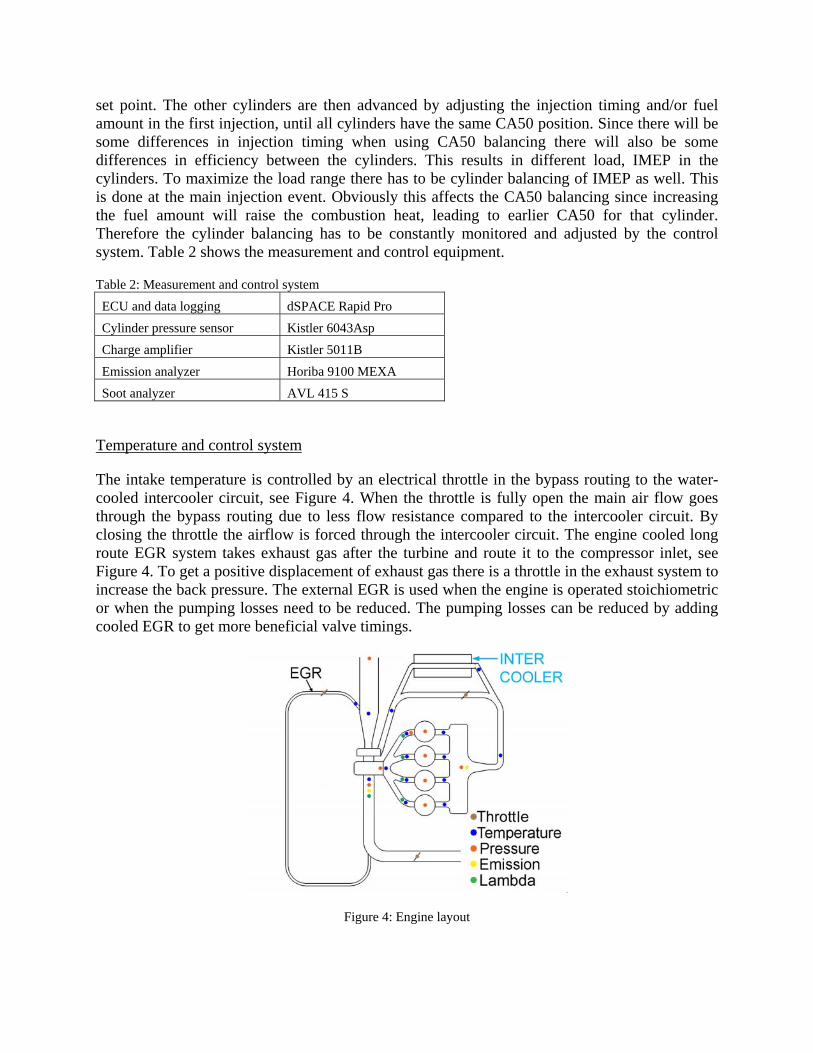
The intake temperature is controlled by an electrical throttle in the bypass routing to the water-cooled intercooler circuit, see Figure 4. When the throttle is fully open the main air flow goes through the bypass routing due to less flow resistance compared to the intercooler circuit. By closing the throttle the airflow is forced through the intercooler circuit. The engine cooled long route EGR system takes exhaust gas after the turbine and route it to the compressor inlet, see Figure 4. To get a positive displacement of exhaust gas there is a throttle in the exhaust system to increase the back pressure. The external EGR is used when the engine is operated stoichiometric or when the pumping losses need to be reduced. The pumping losses can be reduced by adding cooled EGR to get more beneficial valve timings.
Figure 4: Engine layout

RESULTS AND DISCUSSION
Turbocharging To increase the maximum load range in HCCI the combustion noise has to be controlled. When operating with NVO the mass flow through the engine is reduced since hot exhaust gas is trapped in the cylinder to initiate the auto ignition. Controlling the combustion timing with the amount of internal residuals influences the mass flow and therefore available boost pressure. In Figure 5, a CA50 sweep is performed with constant load at 2500 rpm. A later CA50 timing needs less internal residuals due to later EVC timing. As a result the mass flow is increased and hence boosts pressure. Normally in a NVO HCCI engine the intake valve opening (IVO) timing is almost symmetrical to the EVC timing to reduce the pumping work during the gas exchange process. When load and boost pressure is increased, the exhaust and intake temperature are increased meaning that required EVC timing is delayed substantially. With this type of short duration valve timings the intake valve closing (IVC) can therefore be before bottom dead center (BDC). This will reduce the volumetric efficiency and reduce the in-cylinder pressure. In Figure 6, an IVO sweep is performed with a symmetrical starting point to latest possible IVO timing when the CA50 timing is kept constant. This also means that the EVC timing has to be changed continuously as the IVO timing is delayed to keep the chosen combustion timing as seen in Figure 6.
Figure 5: Intake pressure vs. combustion timing
Figure 6: Intake pressure vs. intake valve opening timing
When the boost pressure is increased the intake temperature will increase. A higher intake temperature means that less internal EGR is needed for a set combustion timing. This will lead to an increased mass flow and higher intake pressure as seen in Figure 7. The intake temperature is measured 40mm from the intake valve and the temperature is regulated in the intercooler circuit. The thermal property of the intake system influences the mass flow. Keeping the intake charge hot with for example the heated intake manifold as seen in Figure 3 will increase the mass flow. External cooled EGR can be used when the engine is operated stoichiometric due to high nitrogen oxide (NOx) emissions or to influence the pumping losses. When the external EGR is increased the mass flow through the engine is reduced due to the increased heat capacity of the
190
200
210
220CA50 sweep, 2500rpm, IMEPnet 380kPa
a]P in
take
[kP
1 2 3 4 5 6 745
50
55
CA50 [aTDCf]
EVC
[bT
DC G
E]
240
180
200
220
IVO sweep, 2500rpm, IMEPnet 380kPa
P inta
ke [k
Pa]
50 60 70 80 90
40
50
IVO [aTDCGE]
EVC
[bT
DC G
E]
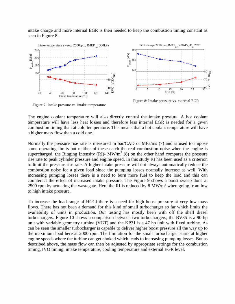
intake charge and more internal EGR is then needed to keep the combustion timing constant as seen in Figure 8.
Figure 7: Intake pressure vs. intake temperature
Figure 8: Intake pressure vs. external EGR
The engine coolant temperature will also directly control the intake pressure. A hot coolant temperature will have less heat losses and therefore less internal EGR is needed for a given combustion timing than at cold temperature. This means that a hot coolant temperature will have a higher mass flow than a cold one. Normally the pressure rise rate is measured in bar/CAD or MPa/ms (7) and is used to impose some operating limits but neither of these catch the real combustion noise when the engine is supercharged, the Ringing Intensity (RI)- MW/m2 (8) on the other hand compares the pressure rise rate to peak cylinder pressure and engine speed. In this study RI has been used as a criterion to limit the pressure rise rate. A higher intake pressure will not always automatically reduce the combustion noise for a given load since the pumping losses normally increase as well. With increasing pumping losses there is a need to burn more fuel to keep the load and this can counteract the effect of increased intake pressure. The Figure 9 shows a boost sweep done at 2500 rpm by actuating the wastegate. Here the RI is reduced by 8 MW/m² when going from low to high intake pressure. To increase the load range of HCCI there is a need for high boost pressure at very low mass flows. There has not been a demand for this kind of small turbocharger so far which limits the availability of units in production. Our testing has mostly been with off the shelf diesel turbochargers. Figure 10 shows a comparison between two turbochargers, the BV35 is a 90 hp unit with variable geometry turbine (VGT) and the KP31 is a 47 hp unit with fixed turbine. As can be seen the smaller turbocharger is capable to deliver higher boost pressure all the way up to the maximum load here at 2000 rpm. The limitation for the small turbocharger starts at higher engine speeds where the turbine can get choked which leads to increasing pumping losses. But as described above, the mass flow can then be adjusted by appropriate settings for the combustion timing, IVO timing, intake temperature, cooling temperature and external EGR level.
160
180
200
220Intake temperature sweep, 2500rpm, IMEPnet 380kPa
P inta
ke [k
Pa]
20 40 60 80 100 120 140
40
60
Intake temperature [°C]
EVC
[bT
DC G
E]
180
140
160
EGR sweep, 2250rpm, IMEPnet 400kPa, Tin 70°C
P inta
ke [k
Pa]
80
0 5 10 15 20 25 3060
70
EGR [%]
EVC
[°b
TDC G
E]

Figure 9: Ringing Intensity and peak pressure rise vs. intake pressure
Figure 10: Turbocharger type vs. intake pressure
A challenge during a load transient with a turbocharger is that the boost pressure is normally lagging. This delayed boost pressure can then lead to an increase of the combustion noise reducing available practical load range. So the question is how to get something that we do not have (boost pressure). Recall that there is cylinder balancing by the control system where part of the fuel is injected during the NVO for fuel reformation. Normally we try to minimize this fuel reformation quantity to increase the efficiency and reduce engine out soot emissions. But for a load transient we can increase this fuel reformation quantity by advancing the injection timing for the first fuel is injection as seen in Figure 11. At this operating point, 2000 rpm and IMEPnet of 400 kPa, the mass flow increased more than 25 % with the more advanced injection timing. This leads to an increase of boost pressure by 20 kPa (the combustion timing is constant at 6° aTDCf here). The increased fuel reformation with more advanced injection has to be counteracted by a reduction of the EVC timing to keep the combustion timing at the right position. As the EVC timing directly controls the mass flow the boost pressure can then be increased even before the actual load transient. As there is a limited amount of fuel that can be used for this reformation depending on exhaust conditions together with the EVC timing, the right fuel quantity has to be set to these conditions to counteract the fuel vaporization cooling effect.
Figure 11: First injection timing vs. intake pressure
0
5
10
Boost sweep, 2500rpm, IMEPnet 380kPaR
I [M
W/m
²]
2
4
6
dP m
ax [b
ar/C
AD
]
120 140 160 180 2005052545658
Pintake [kPa]
EVC
[bT
DC G
E]
Turbocharger comparison at 2000 rpm
IMEPnet [kPa]
P inta
ke [
kPa]
300 350 400 450 500 550 600
100
120
140
160
180
200
220
KP31BV35
140
150
160
SOI 1 sweep, 2000 rpm, IMEPnet 400 kPa
P inta
ke
[kPa
]
34034535035536036550556065
EVC
[bTD
C GE]
Average SOI 1 [bTDCf]

Pumping losses The HCCI mode is known for its low pumping losses mainly due to the possibility to operate the engine unthrottled. With the addition of a turbocharger there is usually an increase of the pumping losses depending on the efficiency of the turbine and the compressor. In Figure 12 it can be seen that the pumping losses increase with load at a fairly high rate in this particular turbocharged HCCI setup with the low duration exhaust camshaft (125° duration). By separating the pumping losses in two parts further information is available:
• PMEP= Throttlingvalve + (Pex - Pin) • Pex - Pin: The pressure loss over turbine/compressor, shown in Figure 12 • Throttlingvalve: The pressure loss over inlet and exhaust valves, shown in Figure 12
The throttling losses originate from the short duration valve timings. For example, at high HCCI load, a late EVC timing is needed which can lead to that the exhaust valve opening (EVO) is after BDC. This will increase the pumping work from the blow-down process. To reduce the throttling losses a wide span of valve timings was evaluated in 1-D simulation to improve efficiency at all operating points. From the simulation result a new exhaust camshaft was manufactured with 25% longer duration. In Figure 13 it can be seen that the new longer duration camshaft manages to reduce the throttling losses substantially. The negative throttling losses at low load for the short duration camshaft are due to the extra fuel reformation with some heat release at TDCGE. At high load the throttling losses were reduced by more than 40 kPa at 2000 rpm, the results at other engine speeds were similar.
Figure 12: PMEP, Pex-Pin, Valve throttling vs. Load
Figure 13: Throttling losses, new vs. old camshaft
50
100
150
Pumping losses at 2000 rpm, KP31
PMEP
[kP
a]
020406080
P ex- P
in [
kPa]
300 400 500 60020406080
100
IMEPnet [kPa]
Thro
ttlin
g [k
Pa]
Throttling losses at 2000 rpm
IMEPnet [kPa]
Thro
ttlin
g [k
Pa]
100
100 200 300 400 500 600 700-20
0
20
40
60
Short duration ExhaustLong duration Exhaust80
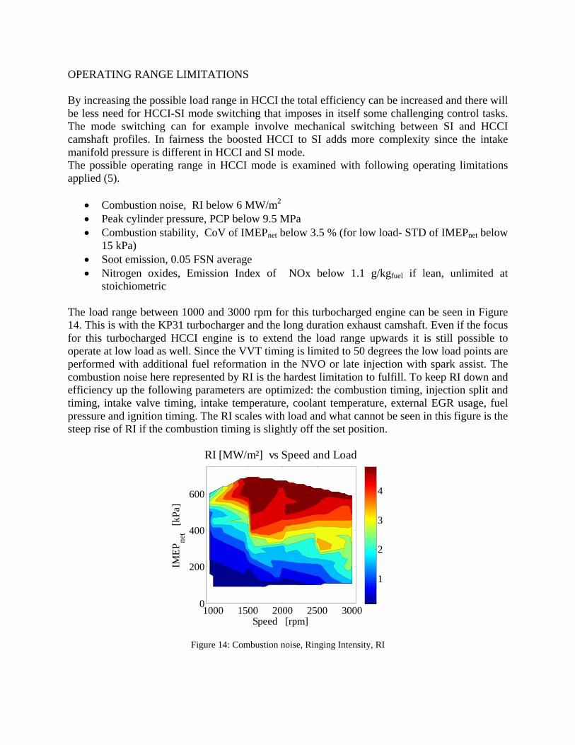
OPERATING RANGE LIMITATIONS By increasing the possible load range in HCCI the total efficiency can be increased and there will be less need for HCCI-SI mode switching that imposes in itself some challenging control tasks. The mode switching can for example involve mechanical switching between SI and HCCI camshaft profiles. In fairness the boosted HCCI to SI adds more complexity since the intake manifold pressure is different in HCCI and SI mode. The possible operating range in HCCI mode is examined with following operating limitations applied (5).
• Combustion noise, RI below 6 MW/m2 • Peak cylinder pressure, PCP below 9.5 MPa • Combustion stability, CoV of IMEPnet below 3.5 % (for low load- STD of IMEPnet below
15 kPa) • Soot emission, 0.05 FSN average • Nitrogen oxides, Emission Index of NOx below 1.1 g/kgfuel if lean, unlimited at
stoichiometric The load range between 1000 and 3000 rpm for this turbocharged engine can be seen in Figure 14. This is with the KP31 turbocharger and the long duration exhaust camshaft. Even if the focus for this turbocharged HCCI engine is to extend the load range upwards it is still possible to operate at low load as well. Since the VVT timing is limited to 50 degrees the low load points are performed with additional fuel reformation in the NVO or late injection with spark assist. The combustion noise here represented by RI is the hardest limitation to fulfill. To keep RI down and efficiency up the following parameters are optimized: the combustion timing, injection split and timing, intake valve timing, intake temperature, coolant temperature, external EGR usage, fuel pressure and ignition timing. The RI scales with load and what cannot be seen in this figure is the steep rise of RI if the combustion timing is slightly off the set position.
Speed [rpm]
IMEP
net
[kPa
]
RI [MW/m²] vs Speed and Load
1000 1500 2000 2500 30000
200
400
600
1
2
3
4
Figure 14: Combustion noise, Ringing Intensity, RI

The intake pressure scales with load and engine speed, as seen in Figure 15. The highest intake pressure is around 220 kPa (abs.). The limiting factor for the boost pressure is the small exhaust turbine which becomes choked at higher engine speeds, but on the other hand it is suitable to deliver boost at small mass flows. The boost pressure directly influences the peak cylinder pressure together with the IVC timing and specific heat ratio. At 2000 to 2500 rpm the PCP is a limiting factor as seen in Figure 16
Figure 15: Intake pressure
Figure 16: Peak cylinder pressure, PCP
HCCI is known for its low Coefficient of Variation (CoV) but normally CoV increases at late combustion timings. When load is increased the easiest way to reduce the combustion noise is to delay the combustion timing and here the turbocharged HCCI has an advantage over the NA HCCI. If there is boost pressure, the turbocharged HCCI engine can operate at a more advanced combustion timing than the NA HCCI engine and thus can increase the efficiency due to higher expansion ratio. This advanced combustion timing will also decrease the CoV for the turbocharged HCCI engine. In Figure 17, the CoV is seen and it is stable except at lowest load but here the operating limit is set by the standard deviation of IMEP instead. At high load or engine speed the CoV can increase drastically with just 1 degree change of the combustion timing which further increases the demand on the control system. Injecting the fuel around TDC when the piston is close to the injector increases the risk for fuel impingement on the piston surface. This leaves a liquid fuel film that can lead to an increase in soot formation. A late injection timing will also increase the soot level and lower the efficiency. The soot level can be reduced by increasing the fuel pressure to enhance fuel vaporization, the fuel injector design together with piston design will also influence soot formation. When the dilution is increased as in the turbocharged HCCI engine soot is usually no problem due to the increased oxygen content. But at low engine speed the mass flow is not enough to increase the intake pressure. This leads to increasing soot emission as seen in Figure 18. The possible load at 1000 rpm was limited by the soot level.
Speed [rpm]
IMEP
net
[kPa
]
in
P [kPa] vs Speed and Load
1000 1500 2000 2500 30000
200
400
600
100
120
140
160
180
200
220
Speed [rpm]IM
EPne
t [k
Pa]
PCP [MPa] vs Speed and Load
9
1000 1500 2000 2500 30000
200
400
600
3
4
5
6
7
8
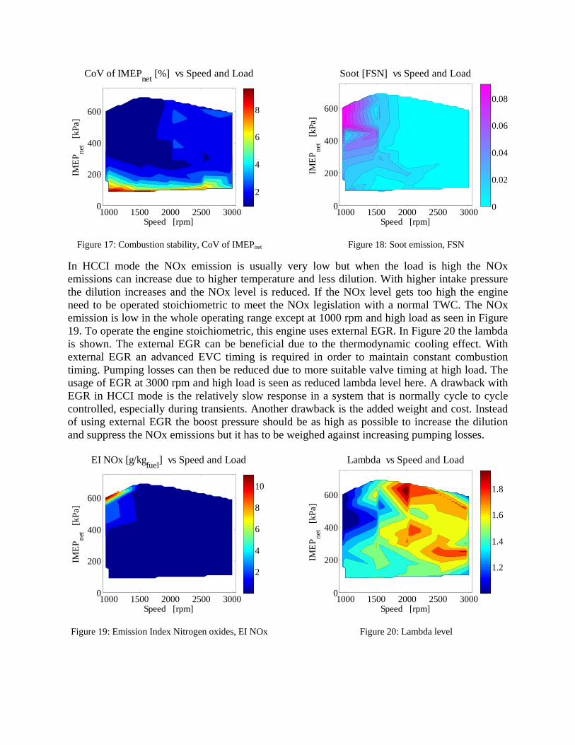
Figure 17: Combustion stability, CoV of IMEPnet
Figure 18: Soot emission, FSN
In HCCI mode the NOx emission is usually very low but when the load is high the NOx emissions can increase due to higher temperature and less dilution. With higher intake pressure the dilution increases and the NOx level is reduced. If the NOx level gets too high the engine need to be operated stoichiometric to meet the NOx legislation with a normal TWC. The NOx emission is low in the whole operating range except at 1000 rpm and high load as seen in Figure 19. To operate the engine stoichiometric, this engine uses external EGR. In Figure 20 the lambda is shown. The external EGR can be beneficial due to the thermodynamic cooling effect. With external EGR an advanced EVC timing is required in order to maintain constant combustion timing. Pumping losses can then be reduced due to more suitable valve timing at high load. The usage of EGR at 3000 rpm and high load is seen as reduced lambda level here. A drawback with EGR in HCCI mode is the relatively slow response in a system that is normally cycle to cycle controlled, especially during transients. Another drawback is the added weight and cost. Instead of using external EGR the boost pressure should be as high as possible to increase the dilution and suppress the NOx emissions but it has to be weighed against increasing pumping losses.
Figure 19: Emission Index Nitrogen oxides, EI NOx
Figure 20: Lambda level
Speed [rpm]
IMEP
net
[kPa
]CoV of IMEPnet [%] vs Speed and Load
1000 1500 2000 2500 30000
200
400
600
2
4
6
8
Speed [rpm]
IMEP
net
[kPa
]
Soot [FSN] vs Speed and Load
1000 1500 2000 2500 30000
200
400
600
0
0.02
0.04
0.06
0.08
Speed [rpm]
IMEP
net
[kPa
]
EI NOx [g/kgfuel] vs Speed and Load
1000 1500 2000 2500 30000
200
400
600
2
4
6
8
10
Speed [rpm]
IMEP
net
[kPa
]
Lambda vs Speed and Load
1000 1500 2000 2500 30000
200
400
600
1.2
1.4
1.6
1.8

PROGRESS The maximum operating range in this turbocharged HCCI engine has been increased during the project time due to improvement in hardware and operating strategies. In Figure 21 this evolution is seen. A baseline for comparison is the same engine in NA setup with the same operating limitations as for the turbocharged version. The main improvement in load range has come with a suitable turbocharger and reduction of the throttling losses by the long duration exhaust camshaft. There are still many areas left for improvement of this operating range, for example with a turbocharger adapted to HCCI, modification of the engine hardware and refinements of the control strategy. The question is then why do we want to operate in HCCI mode? What we are trying to do is to improve the efficiency of the SI engine at low load and still keep the basic SI engine structure. When looking at the brake specific fuel consumption in Figure 22, the efficiency is rather even in the whole operating range except at low load and engine speed. One of this turbocharged HCCI project goals was to extend the operating range to a BMEP level above 500 kPa between 1000 and 3000 rpm with described operating limitations and this was also fulfilled. The area left for most improvement in this turbocharged HCCI engine is the gas exchange process as seen in Figure 23. At low load the efficiency is over 100 % due to some heat release during the NVO. The main pumping loss is from the turbocharger and the rest is then the valve throttling losses. In Figure 24 there is a comparison of this turbocharged HCCI engine and a direct injected 2.0 l turbocharged engine. The improvement can be up to 35% at low load. At the highest operating load there is no real improvement for this turbocharged set-up mostly due to the low gas exchange efficiency.
Figure 21: Maximum load range progress
Figure 22: Brake specific fuel consumption, bsfc
Lund turbo HCCI progress
Speed [rpm]
IMEP
net [
kPa]
Speed [rpm]
BM
EP
[kPa
]
bsfc [g/kWh] 2.2 l HCCI turbo vs Speed and Load
1000 1500 2000 2500 3000
300
400
500
600
700
Turbo 2009-10-01Turbo 2008-07-15Turbo 2008-04-11Turbo 2007-07-10NA 1000 1500 2000 2500 3000
100
200
300
400
500
600
260
280
300
320
340
360
380

Figure 23: Gas exchange efficiency
Figure 24: HCCI vs. SI engine, bsfc difference
SUMMARY AND CONCLUSIONS
In this paper it has been shown that the intake pressure in this turbocharged NVO HCCI engine depends on many variables. The mass flow and therefore the boost pressure can be altered by the combustion timing, the intake valve timing, the intake temperature and external EGR. This multi-dimension possibility gives the opportunity to operate turbocharged HCCI efficiently in a wide load and engine speed range. The soot emission limited the load range at 1000 rpm. At higher loads the combustion noise is always a challenge and RI limited operation at 1500 rpm. With the increased intake pressure the peak cylinder pressure limited the operating range at 2000 to 2500 rpm. At 3000 rpm the load range was limited by the turbocharger. The combustion stability was the limiting factor for minimum load at all engine speeds. With this turbocharged HCCI engine the NOx emission is low when there is boost pressure and did not limit operating range. At 1000 rpm the small mass flow was not enough to increase the intake pressure and the NOx emission rose above the set limit and the engine had to be operated stoichiometric. A challenge with turbocharging and HCCI can be the delayed boost pressure during a load transient increasing the combustion noise. It is shown that by increasing the fuel reformation during the negative valve overlap the mass flow is increased leading to higher intake pressure. This can be used even before the actual load transient. By choosing a better sized turbocharger it was possible to increase the operating range due to higher intake pressure leading to a reduction of the combustion noise. When the HCCI engine is turbocharged and operated at high load the pumping losses can be high, but these could be reduced substantially with the increased exhaust valve duration. It is shown that this turbocharged HCCI engine can have up to 35 % improvement in specific fuel consumption when compared to a modern direct injected turbocharged SI engine.
Speed [rpm]
IMEP
net
[kPa
]ηGE [%] vs Speed and Load
1000 1500 2000 2500 30000
200
400
600
80
85
90
95
100
105
110

REFERENCES (1) Christensen, M., Johansson, B., Amnéus, P. Mauss, F., "Supercharged homogeneous charge
compression ignition," SAE Technical Paper 980787, 1998. (2) Christensen, M., Johansson, B., "Supercharged homogeneous charge compression ignition
(hcci) with exhaust gas recirculation and pilot fuel," SAE Technical Paper 2000-01-1835, 2000.
(3) Hyvönen, J., Haraldsson, G., Johansson, B., "Supercharging HCCI to extend the operating range in a multi-cylinder VCR-HCCI engine," SAE Technical Paper 2003-01-3214, 2003.
(4) Olsson, J-O., Tunestål, P., Johansson, B., "Boosting for high load HCCI," SAE Technical Paper 2004-01-0940, 2004.
(5) Johansson, T., Johansson, B., Tunestål, P., Aulin, H., "HCCI operating range in a turbo-charged multi cylinder with VVT and spray- guided DI," SAE Technical Paper 2009-01-0494, 2009.
(6) Johansson, T., Johansson, B., Tunestål, P., Aulin, H., "The effect of Intake Temperature in a Turbocharged Multi Cylinder Engine operating in HCCI mode," SAE Technical Paper 2009-24-0060, 2009.
(7) Andreae, M.M, Cheng, W.K., Kenney, T., Yang, J., "On HCCI Engine Knock," SAE Paper 2007-01-1858, 2007.
(8) Eng, J.A., "Characterization of pressure waves in HCCI combustion," SAE Technical Paper 2002-01-2859, 2002.