turbomachine sealing and secondary flows - nasa. hendricks, b.m. steinetz, and e.v. zaretsky glenn...
TRANSCRIPT

R.C. Hendricks, B.M. Steinetz, and E.V. ZaretskyGlenn Research Center, Cleveland, Ohio
M.M. Athavale and A.J. PrzekwasCFD Research Corporation, Huntsville, Alabama
Turbomachine Sealing and Secondary FlowsPart 3—Review of Power-Stream Support, Unsteady FlowSystems, Seal and Disk Cavity Flows, Engine Externals,and Life and Reliability Issues
NASA/TM—2004-211991/PART3
July 2004
https://ntrs.nasa.gov/search.jsp?R=20040086723 2018-06-17T23:22:45+00:00Z

The NASA STI Program Office . . . in Profile
Since its founding, NASA has been dedicated tothe advancement of aeronautics and spacescience. The NASA Scientific and TechnicalInformation (STI) Program Office plays a key partin helping NASA maintain this important role.
The NASA STI Program Office is operated byLangley Research Center, the Lead Center forNASA’s scientific and technical information. TheNASA STI Program Office provides access to theNASA STI Database, the largest collection ofaeronautical and space science STI in the world.The Program Office is also NASA’s institutionalmechanism for disseminating the results of itsresearch and development activities. These resultsare published by NASA in the NASA STI ReportSeries, which includes the following report types:
∑ TECHNICAL PUBLICATION. Reports ofcompleted research or a major significantphase of research that present the results ofNASA programs and include extensive dataor theoretical analysis. Includes compilationsof significant scientific and technical data andinformation deemed to be of continuingreference value. NASA’s counterpart of peer-reviewed formal professional papers buthas less stringent limitations on manuscriptlength and extent of graphic presentations.
∑ TECHNICAL MEMORANDUM. Scientificand technical findings that are preliminary orof specialized interest, e.g., quick releasereports, working papers, and bibliographiesthat contain minimal annotation. Does notcontain extensive analysis.
∑ CONTRACTOR REPORT. Scientific andtechnical findings by NASA-sponsoredcontractors and grantees.
∑ CONFERENCE PUBLICATION. Collectedpapers from scientific and technicalconferences, symposia, seminars, or othermeetings sponsored or cosponsored byNASA.
∑ SPECIAL PUBLICATION. Scientific,technical, or historical information fromNASA programs, projects, and missions,often concerned with subjects havingsubstantial public interest.
∑ TECHNICAL TRANSLATION. English-language translations of foreign scientificand technical material pertinent to NASA’smission.
Specialized services that complement the STIProgram Office’s diverse offerings includecreating custom thesauri, building customizeddatabases, organizing and publishing researchresults . . . even providing videos.
For more information about the NASA STIProgram Office, see the following:
∑ Access the NASA STI Program Home Pageat http://www.sti.nasa.gov
∑ E-mail your question via the Internet [email protected]
∑ Fax your question to the NASA AccessHelp Desk at 301–621–0134
∑ Telephone the NASA Access Help Desk at301–621–0390
∑ Write to: NASA Access Help Desk NASA Center for AeroSpace Information 7121 Standard Drive Hanover, MD 21076

R.C. Hendricks, B.M. Steinetz, and E.V. ZaretskyGlenn Research Center, Cleveland, Ohio
M.M. Athavale and A.J. PrzekwasCFD Research Corporation, Huntsville, Alabama
Turbomachine Sealing and Secondary FlowsPart 3—Review of Power-Stream Support, Unsteady FlowSystems, Seal and Disk Cavity Flows, Engine Externals,and Life and Reliability Issues
NASA/TM—2004-211991/PART3
July 2004
National Aeronautics andSpace Administration
Glenn Research Center

Available from
NASA Center for Aerospace Information7121 Standard DriveHanover, MD 21076
National Technical Information Service5285 Port Royal RoadSpringfield, VA 22100
Available electronically at http://gltrs.grc.nasa.gov
Note that at the time of research, the NASA Lewis Research Centerwas undergoing a name change to the
NASA John H. Glenn Research Center at Lewis Field.Both names may appear in this report.

NASA/TM—2004-211991/PART3 1
Turbomachine Sealing and Secondary FlowsPart 3—Review of Power-Stream Support,
Unsteady Flow Systems, Seal and Disk Cavity Flows,Engine Externals, and Life and Reliability Issues
R.C. Hendricks, B.M. Steinetz, and E.V. ZaretskyNational Aeronautics and Space Administration
Glenn Research CenterCleveland, Ohio 44135
M.M. Athavale and A.J. PrzekwasCFD Research CorporationHuntsville, Alabama 35805
Abstract
The issues and components supporting the engine power stream are reviewed. It is essential thatcompanies pay close attention to engine sealing issues, particularly on the high-pressure spool orhigh-pressure pumps. Small changes in these systems are reflected throughout the entire engine.Although cavity, platform, and tip sealing are complex and have a significant effect on componentand engine performance, computational tools (e.g., NASA-developed INDSEAL, SCISEAL, andADPAC) are available to help guide the designer and the experimenter. Gas turbine engine and rocketengine externals must all function efficiently with a high degree of reliability in order for the engineto run but often receive little attention until they malfunction. Within the open literature statisticallysignificant data for critical engine components are virtually nonexistent; the classic approach isdeterministic. Studies show that variations with loading can have a significant effect on componentperformance and life. Without validation data they are just studies. These variations and deficits instatistical databases require immediate attention.
Keywords: Turbomachine, seals, secondary flow, engine externals, component life
Introduction
Many components in today’s turbomachines were designed “on the boards” by competent,knowledgeable engineers based on sound fundamentals. Although standard in the past, this practiceis rapidly yielding to component solid modeling with the designer able to access interfacingcomponents and perform some degree of optimization, including material selection and stressanalyses. In many respects the designer knows more and has more information at each stage of thedesign but in other ways often lacks the hands-on knowledge and competency of the seasonedengineer. There is no substitute for in-field experience and feedback data. Further, we are rapidlyapproaching performance limits in terms of what can be accomplished through “material bending,”and unsteady fluid flows are becoming the next performance challenge.
Turbomachine sealing and cavity flow problems are unsteady in nature owing to the blade/vaneinteraction of the rotating system, and the challenge becomes how to best analyze and use these flows.Validated tools must be developed to assist the designer and engineer with steady and unsteady flowand heat transfer issues relating to power-stream and overall engine performance. For example,
NASA/TM—2004-211991/PART3 2
multiply-connected cavities with conjugate heat transfer must be considered in detail when seekingsmall percentage gains in component efficiency. It is equally important to account for disk and bladeor vane cooling and purge flows because small changes in thermal and flow characteristics effectlarge changes in engine life and can degrade engine performance. Most of these flows are controlledby compressor or pump bleeds through fixed orifices, but many are controlled through seals, valves,pipes, and controllers, constituting a small portion of the engine externals.
Engine externals, all the “stuff” hanging on the engine case, are too often neglected in a researchprogram. However, without engine externals the engine simply will not operate. Because thecomplexity of the externals space does not lend itself readily to modeling, one resorts to experiment,even for such critical functions as fire prevention. Nevertheless, engine externals account for a largepercentage of the day-to-day maintenance problems and influence engine life.
Maintenance intervals and component lifing are critical issues to both the astronauts and thetraveling public. The airlines and NASA work very hard to ensure safety and component reliability.Nevertheless, component design life is still established through testing and history, and improve-ments in lifing methods are both necessary and continually sought.
In part 1 we review some sealing requirements and limitations from the viewpoints of thecustomer, designer, and researcher along with marketing forces. In part 2 we explore turbomachinesealing dynamics methods and computational and numerical modeling. Herein, we address the issuesof multiply-connected cavities with conjugate heat transfer, the nature of compressor and turbineblade flows, and the interaction and complexity of engine externals and illustrate some facets ofcomponent lifing.
Unsteady Flow Systems
As cited in part 2, turbomachines are unsteady systems that induce unsteady loadings into thebypass (fan) and the power and the secondary flow streams. In addition, each stage of the fan,compressor, and turbine cavities must be pressure and load balanced on one, two, or three spools.Usually, one considers a gas-generator spool, or high spool, and a power spool, or low spool.However, each manufacturer optimizes to produce the best power, economy, and environmentalratings for the cost.
As an example of air-breathing turbomachines the NASA Energy Efficient Engine (E3) has a T1turbine (first stage of the high-pressure turbine) with 76 blades and 46 stators. The objective is toproduce hot, high-pressure gas to drive the high-pressure compressor. The low-pressure turbinepowers the low-pressure compressor and fan. These systems require long life and high reliability.Thus, rapidly pulsing combustion gases must be kept from the cavities and confined to the bladeplatform regions without reingestion into the turbine or compressor flow streams, which degradesperformance. Also, unsteady blade tip flows must be controlled with minimal losses, thus preventingseparating, flow passage blockage, stall, or unstart. In addition, the interface purge and cooling airmust be properly metered and sealed to provide load balancing.
Rocket engine turbomachines have similar interfacing and load-balancing problems, but theflight profile requirements are more severe. Combinations of cryogens, rapid startup, high rotorspeeds, propellant-lubricated bearings, very high strength/weight ratio components, and dynamicsare sealing and secondary flow design challenges. Looking ahead, valved and valveless pulse andcontinuous-wave detonation engines being developed are unsteady devices that present yet anotherset of sealing challenges to contain reflected shocks and maintain proper inlet pressures within thecombustion tube.

NASA/TM—2004-211991/PART3 3
Seal and Disk Cavity Flows
Although this is by no means intended as a comprehensive review, we will highlight a fewimportant findings. A considerable amount work has been performed on fluid flow and heat transfermechanisms in cavities formed within rotating and stationary disks. Figure 1 shows a typicalmultistage turbine cavity section. Several experimental studies have been reported that consider bothsimplified and complex disk cavity configurations (e.g., Chen, 1991; Chew et al., 1988, 1992; Graberet al., 1987; and Johnson et al., 1991, 1994).
(a)
Fifth-stagecompressor bleed
Fan airFan air
Seventh-stagecompressor bleed
Nozzleair supply
Inducerseal
Diffuserbleed
Compressordischargeseal
Expandernozzle
Sealblockageair
(b)
Shroud sealTurbine blades
Stator vanes
Interstageseal
Turbinedisk
Turbine disk
Compressorair
Figure 1. —Typical multistage turbine cavity section. (a) Energy Efficient Engine high- pressure turbine (Halila et al., 1982). (b) Hypothetical turbine secondary-air cooling and sealing (Allcock et al., 2002). Courtesy AIAA. See also figures 13 and 5 of part 1.

NASA/TM—2004-211991/PART3 4
Hendricks et al. (1995) set forth a comprehensive review of secondary flow system develop-ments with the power stream in aerospace components for the NASA seals and secondary flowsystem codes SCISEAL and INDSEAL. These development efforts are also tracked in the NASASeals Code and Secondary Flow Systems Development publications (1991 to present). The couplingof the power-stream flows with seals and cavity flows is a necessary aspect of multistage compressorand turbine design. Athavale et al. (1997, 1998) have reported detailed descriptions of these tools andrepresentative simulations. (See also Janus et al., 1989, 1992.)
These works include the gas-path flows through the stages (blades and vanes) and those underthe platform cavity and in the sealing region. The interaction between these two flow streamssignificantly affects performance. The tip sealing (shroud/rotor and interstage/stator interfaces) isequivalently important and can be handled in a similar manner. However, for this discussion we willconfine our attention to the region between the shaft and the blade or vane platforms. The interstage/labyrinth/rim seal interface design, locations, and requirements differ between the compressor andthe turbine. For example, on the compressor side the goals are to keep leakage small, to reducewindage, and to mitigate the reintroduction of flow into the gas path. On the turbine side, the goalsare to reduce losses and to prevent gas-path ingestion with careful attention to rim sealing (fig. 1).
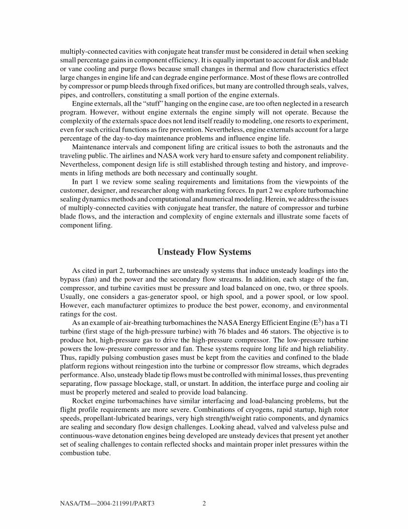
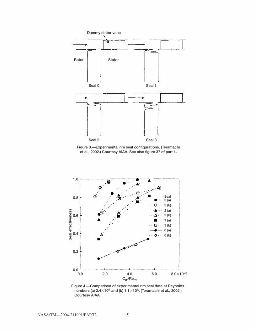
Teramachi et al. (2002) investigated rim interface sealing (figs. 2 and 3), providing data and somecomputational fluid dynamics (CFD) results on four rim seal configurations: (0) T-on rotor, (1) T-onrotor with overlap T-on stator, (2) T-on stator with overlap T-on rotor; and (3) fish mouth on rotorwith overlap T-on stator. Dummy stators were introduced, but there were no blades on the rotor.Carbon dioxide concentration measurements (similar to the work of Bruce Johnson (Graber et al.,1987)) defined seal effectiveness in terms of the ratio of purge gas to ingested gas. Figure 4 showsthe experimental effectiveness of these configurations, where flow coefficient Cw = Q/νb and Rem= Vb/ν, where b is the cavity outer radius, V the mean flow speed, Q the purge flow rate, and ν thekinematic viscosity. Configuration (3) is the least affected by changes in overlap and configurationand (0) the most; configuration (2) is quite sensitive to overlap. The high effectiveness of
Figure 2.—Generic turbine nozzle rotor gap configuration. (Campbell, 1978). See also figure 7 of part 1.
c s
A
h
IrIn
NASA/TM—2004-211991/PART3 5
Figure 3.—Experimental rim seal configurations. (Teramachi et al., 2002.) Courtesy AIAA. See also figure 37 of part 1.
Dummy stator vane
Rotor Stator
Seal 2 Seal 3
Seal 0 Seal 1
Figure 4.—Comparison of experimental rim seal data at Reynolds numbers (a) 2.4�106 and (b) 1.1�106. (Teramachi et al., 2002.) Courtesy AIAA.
0.0 2.0 4.0 6.0Cw/Rem
8.0�10–3
1.0
Sea
l eff
ectiv
enes
s
0.8
0.6
0.4
0.2
0.0
3 (a)
3 (b)
2 (a)2 (b)
1 (a)
1 (b)0 (a)
0 (b)
Seal

NASA/TM—2004-211991/PART3 6
configuration (3) is related to the buffer cavity between the two rotor seal teeth with a stator toothbetween the rotor teeth. The lowest effectiveness of configuration (1) is due to the large clearancegap, although the ingestion is nearly zero. A CFD code jointly developed by the National AerospaceLaboratory–Japan and the University of Manchester’s Institute of Science and Technology (turbu-lent, k-ε, with wall functions) was applied to these configurations. The results show the gaprecirculation zone where power-stream gas is ingested at on-pitch positions and ejected at midpitchpositions (i.e., flow ingestion at the vane leading edge partially returns in the midpitch region mixingwith the purge air; see also Wellborn and Okiishi, 1996). Athavale et al. (1999) in studying theAllison 501D turbine found that ingested fluid could work its way well into the disk space, eventhough purge fluid flows were substantial.
Wellborn and Okiishi (1996, 1999) investigated the effect of leakage in a four-stage, low-pressure compressor with blading design based on the NASA E3 engine. Figure 5 illustrates theNASA Glenn low-speed, axial-flow compressor’s (LSAC) stage 3 cavity geometry. For theconfiguration tested there was a monotonic decrease in performance with increased leakage but noobservable effect on stall margin. Variations in performance due to seal leakages were localized atthe bottom 0.4 of span, but there was a region of blockage near the hub due to recirculating leakageflow. Flow was injected into the power stream near midpitch of the upstream cavity and sucked intothe cavity near the blade stagnation point. Flow is into the cavity over most of the downstream cavity,with localized ejection near the stator wakes. Here, low tangential or axial momentum in the upstreamcavity degraded the suction-side boundary layer. Seal leakages did not affect upstream stages but didprogressively degrade performance of the downstream stages. For each 1 percent change inclearance/span ratio the pressure rise penalty was nearly 3 percent with a 1-percent drop in efficiency.Hall and Delaney (1993a,b, 1995) simulated the LSAC experiments with Adamczyk’s ADPACanalysis package. (They also completed sensitivity studies but did not address the effects onrotordynamics.)
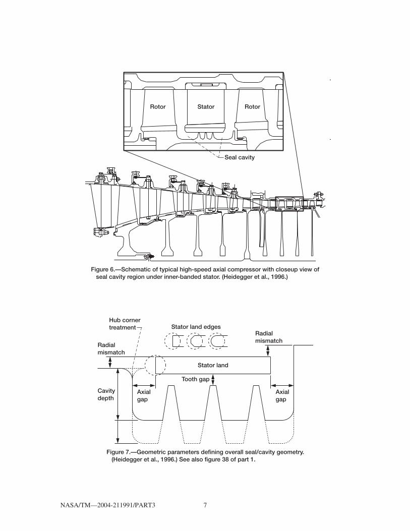
Very few studies on the full-time, accurate interaction of nonaxisymmetric flow on the rim sealare available. Heidegger et al. (1996) presented three-dimensional solutions of the interactionbetween the power stream and seal cavity flow in a typical multistage compressor (fig. 6). Using theAllison/NASA-developed ADPAC code, they performed a parametric study on a three-toothlabyrinth seal/cavity configuration (fig. 7) and a sensitivity study to various sealing parameters(fig. 8). Figure 9 nicely images a class of generic labyrinth seal tooth geometries. Their study shows
Figure 5.—Illustrations of low-speed compressor shroud sealing configurations at rotor (hub)/stator interface. (a) No cavity with nominal zero leakage. (b) Minimum-leakage cavity. (c) Baseline cavity; intermediate and maximum leakage with clearance changes. (Wellborn and Okiishi, 1996.) See also figures 6 and 7.
(a) (b)
(c) Shim
Extensions
Shim Shim
Seal tooth
Seal toothSeal tooth
Hub
HubHub
Balsa Balsa
Cherry
Foot ring
Foot ring Foot ring
NASA/TM—2004-211991/PART3 7
Figure 6.—Schematic of typical high-speed axial compressor with closeup view of seal cavity region under inner-banded stator. (Heidegger et al., 1996.)
StatorRotor
Seal cavity
Rotor
Figure 7.—Geometric parameters defining overall seal/cavity geometry. (Heidegger et al., 1996.) See also figure 38 of part 1.
Axialgap
Axialgap
Tooth gap
Cavitydepth
Hub cornertreatment
Radialmismatch
Stator land edges
Stator land
Radialmismatch

NASA/TM—2004-211991/PART3 8
that the leakage flow out of the seal cavities can affect the power stream significantly, mainly byaltering the inlet flow near the stator blade root area, and can potentially affect the performance ofthe overall compressor (fig. 10). Feiereisen et al. (2000) completed an experimental study of theprimary and secondary flow in a turbine rig. It represents a first attempt at understanding thisinteraction and at generating data for validation.
CFD techniques are increasingly being used to provide detailed flow field information on morecomplex cavity shapes and complex flow phenomena that cannot be treated with analytical methods.Several studies on single-cavity configurations with simplified geometry have been reported (e.g.,Athavale et al., 1992; Chew, 1988; and Virr et al., 1994). The cavities considered in these studies wereof the rotor-stator type with a rim seal and coolant injection. Some measure of interaction with main-path flow was provided. As noted in figures 1 and 6, an engine has multiple, linked disk cavities, withcomplex shapes including bolts and holes. CFD techniques provide a way to account for the complexinteraction in such configurations, but even then simplifications are required. Several studies oncomplete turbine drum simulations have been reported (Athavale et al., 1995; Ho et al., 1996).
Figure 8.—Test matrix of geometric parameters to be tested relative to baseline configuration. (Heidegger et al., 1996.) See also figure 39 of part 1.
Parameter Variations
Seal tooth gap
0.010 in.
0.184 in.
100%
Wheel speed (rpm)
Seal cavity depth
Axial trench gap:
Leading edgeTrailing edge
UpstreamDownstream
SharpSharp
Faceted
0.081 in.0.061 in.
UpstreamDownstream
0.000 in.0.000 in.
Hub cornertreatment:
Stator land edgetreatment
Radial mismatch ofhub flow path:
Baselinecase
58% baseline speed
± 20% of baseline gap
Faceted Rounded
Sharp Roundedforward
Roundedback
No cavity, no gap,0.020 in., 0.040 in.
± 50% of baseline cavity depth
± 5% stator span± 5% stator span

NASA/TM—2004-211991/PART3 9
Figure 9.—Geometric parameters defining individual and generic seal tooth geometries. (Heidegger et al., 1996.) See also figure 40 of part 1.
Flat Sharp Rounded
Seal toothtipsGroove
depth
Slantangle
Toothgap
Tooththickness
Wedge angleSlantedtooth
Embeddedtooth
Invertedtooth
Standardtooth
Figure 10.—Contours of radial velocity located one computational cell above hub (rotor) surface for coarse mesh. (a) Unsteady and (b) mixing-plane rotor/ stator/rotor ADPAC solutions. (Heidegger et al., 1996.)
(a)
(b)
Positive radialflow exiting trenchnear stator land
Positive radialflow exiting trenchnear stator land
"Zero" radialflow in bladepassage
Negative radialflow into trenchtied to rotorleading edge
Negative radialflow into trench"smeared" bymixing plane

NASA/TM—2004-211991/PART3 10
In the treating coupled flows consider where and when model simplification can be used. Oftentwo-dimensional or steady-state flow and heat transfer can be used as opposed to a completeconservative three-dimensional transient with fully coupled interactions including conjugate heattransfer. However, conjugate heat transfer is important in calculating disk temperature distributions.For example, as figures 11 to 14 show, the calculated interaction between power-stream and secondaryflows would not match the Allison 501D turbine results without conjugate heat transfer (Ho et al., 1996;Athavale et al., 1999). Conjugate heat transfer is most important in determining the T1-rotor platformtemperatures, especially at the power-stream interfaces where the thermal gradient from the platformto the hub is significant. These aerothermalmechanical loads can drastically affect disk and enginelife, as discussed later. (It is also important to include geometric deformation. Because deformationis not yet a part of SCISEAL, a separate finite element analysis code must be used.)
So the objectives are to develop a simulation methodology for coupled solutions of the power-stream and secondary flow fields considering (1) transient, coupled two-dimensional simulations,extending the NASA seals and secondary flow systems code and (2) “steady-state” simulations forquick-turnaround preliminary designs that can be interfaced and augmented with the NASA sealscode INDSEAL. Either method requires both time-accurate and steady-state validation againstavailable data, followed by extensive beta testing of the codes and feedback by the original enginemanufacturers (OEM’s). For the transient coupled simulations the code SCISEAL for below-platform flows is coupled with MS–TURBO for power-stream flows. These codes treat the flowphysics differently, requiring special information transfer techniques at the interface. SCISEAL isa pressure-based, turbulent, heat-and-mass-transfer (including conjugate), slower-flow code.MS–TURBO is a density-based, unsteady, rotor-stator interactive, fast-flow code. At the interfacethe primitive variables of SCISEAL are passed to MS–TURBO, and the primitive variables of the
Figure 11.—Flow domain and conditions for conjugate heat transfer calculations of all inner disk cavity pairs. Shaded areas denote conjugate heat transfer. Static pressures are specified at six main flow exits. (Athavale et al., 1999.)
Isothermalwall
Isothermalwall Isothermal
wall
Isothermalwall
Isothermalwall
Rotor(14 239 rpm)
Rotor(14 239 rpm)
Adiabatic wall
Adiabaticwall
Main flow 1 Main flow 2Main flow 3
Main flow 4
Main flow 5
Main flow 63
A
B
C
D
6
4
51
2
Isothermalwall
Purge flowlocation
Purge flow location
Isothermalwall
Isothermalwall
Statorsupport

NASA/TM—2004-211991/PART3 11
Figure 12.—Temperature field in fluid and solid parts of turbine cavities (absolute frame). (Athavale et al., 1999.)
Temperature,K
1240118011201050988924860796732668604
1240
1180
1120
1050
988
924
860
796
732
668
604
Figure 13.—Details of streamlines and temperatures in stage 1-2 cavities with conjugate heat transfer (absolute frame). (Athavale et al., 1999.)
Temperature,K

NASA/TM—2004-211991/PART3 12
MS–TURBO boundary ghost layer are used to calculate interface fluxes. These fluxes are thenpassed to SCISEAL as the interface boundary conditions, ensuring continuity of fluxes across theinterface, while TURBO controls the time steps requiring proper code synchronization to transferdata files (fig. 15).
To minimize solution times, SCISEAL could be used to treat both the power-steam and below-platform flow as was done by Heidegger et al. (1996) with the Allison/NASA-developed ADPACcode. The time dependency of relative motion issues would be resolved, but circumferentialaveraging for the sliding interfaces would be required (fig. 16). Using SCISEAL would provide a fastway of assessing a particular design, allowing treatment of complex cavity-rim configurations andnear-term optimization, and would serve as the starting point for the time-accurate calculations usingthe coupled SCISEAL and MS–TURBO codes. (This single-code SCISEAL procedure, three-dimensional at the mixing plane in the power stream and two-dimensional in the cavity, for steady-state calculations is still in the process of being finished.)
The coupled codes SCISEAL and MS–TURBO (Athavale et al., 2001) have been applied toseveral experimental test rig data sets showing conditions under which ingested flow can becontrolled. Consider the configuration illustrated in figure 17 and its associated computational grid(fig. 18). Athavale applied the code to the 30° pi-sector with four vanes (stators) and five blades(rotors) simulating the stator/rotor set (48/58) of Feiereisen et al. (2000), with a three-tooth labyrinthseal and overlap rim seals. The stator grid is 49 axial by 12 radial by 15 circumferential (tangential);the rotor grid is 36 by 12 by 12, a coarse grid. The interface zone is 8 axial by 60 circumferential(tangential) for the power stream and 8 by 30 for the cavity. The TURBO code (the version employedin the study) did not have the k-ε turbulence model, and the boundary values at the interface had tobe inferred or estimated from the presumed rim seal solution. The interface values of k and ε affectthe turbulent viscosity in the critical flow area of the rim seal. Improper specification of the k-ε valuesat the interface destabilized the solution at low purge flow rates. The calculation procedureimmediately stabilized after reasonable values of turbulent parameters were used at the rim sealinterface.
Figure 14.—Stream function and conjugate heat transfer temperature fields in stage 2-3 and 3-4 cavities (absolute frame). (Athavale et al.,1999.)
1240
118011201050988924860
796732
668604
Temperature,K

NASA/TM—2004-211991/PART3 13
Figure 16.—Schematic of a typical interstage cavity configuration with sliding interface boundary con- dition. (Athavale et al., 2001.)
Slidinginterface
Statorstage
Slidinginterface
Rotor stage
Rotor/statordisk cavity
Interstage labyrinthseal
Rotor stage
Purge andcoolant flow
Interfacebetweenprimary andsecondaryflow at rimseal
Figure 15.—Flow schematic for coupled execution of SCISEAL and TURBO codes. (Athavale et al., 2001.) PVM (parallel virtual machine); MPI (message passing interface).
Stop
Execution ofone iteration
Time for dataexchange withTURBO
Time for dataexchange withSCISEAL
No
No
No
No
Maximumtime reached ?
Completepostprocessingdata storage, etc.
Sufficientiterations forone time step ?
Yes
Yes Yes
Yes Yes
No
Data transfer
Data transfer
Datatransfer
Exchange data
PVM or MPIdata exchange
Structuraland thermaldeformation
SCISEAL (singleor multiple CPU)
TURBO (singleor multiple CPU)
Initialization andrestart for SCISEALand TURBO
Check grids andboundary conditionsfor consistency, etc.
Start
Single ormultiple CPU's
Time advance
Postprocessor
Execution ofone iteration
Sufficientiterations forone time step ?

NASA/TM—2004-211991/PART3 14
Figure 19 shows the experimental pressure trace for 0 percent purge flow rate at the midcavitytap. Two points to be noted are (1) the amplitude of the experimental pressure trace is of the orderof 12 Pa for a 0 percent purge flow rate (fig. 19), similar in magnitude to the simulated results, and(2) the calculated amplitude of pressure fluctuations increased with a higher (0.69 percent) purgeflow rate (fig. 20).
Transient Pressures in Rim Seal
Experimental transient pressure at the pressure tap located under the stator vane platform has anamplitude of approximately 21 Pa for 0 percent cavity purge. This amplitude doubles to about 42 Paat 2.83 percent purge flow rate. The calculated amplitude is approximately 50 Pa. These values aresensitive to the grid-clicking frequency.
Figure 18.—Computational grid in disk cavity of high-pressure rig. (Athavale et al., 2001.)
Figure 17.—Locations of pressure taps in United Technologies Research Corp. experimental rig. Dots denote steady-pressure, circle-transient pressure measurements. (Athavale et al., 2001.)
Purgeflow
1
9
–5050
55.6–44.4
–83.3516.65
50(dynamictransducer)
54
12
13IGV
Vane gap,percent
Blade gap,percent
Mainpath Rotor
1
Figure 19.—Experimental transient trace for cavity pressure (with respect to a mean value) on rotor wall for 0 percent purge flow. (Athavale et al., 2001.)
20.0
10.0
00.0
–10.0
–20.00.000
Diff
eren
tial p
ress
ure,
Pa
0.001 0.002Time, s
0.003

NASA/TM—2004-211991/PART3 15
Figures 21 and 22 show the time-varying flow fields in the cavity for the two purge rates (0.69and 2.83 percent; purge efficiency parameter η = 0.005 and 0.02, respectively1) at the aligned andmidspan rotor positions. Figure 23 shows the surface pressure and velocity contours of the main pathfor a 2.83 percent purge flow rate. The cutting plane in these plots occupies a “midpassage” locationin relation to the stator blade row. The recirculation zone in the rim seal present at the lower purgeflow rate is absent at the higher purge flow rate. The recirculation allows some of the power stream
1
ηπ µ
ω νω
µ ν
= =
= =
Re
Re
( ˙ / )
( / )
˙
. .feed
turbine
where Re = Reynolds number, = rotor rim radius, = turbine angular rotation,
dynamic viscosity, = kinematic viscosity, purge gas mass flow rate.
0 8 2 0 8
2m r
rr
m
Figure 20.—Calculated transient trace for cavity pressure on rotor wall for 0.69 percent purge flow. (Athavale et al., 2001.)
119100.0
Pre
ssur
e, P
a
119080.0
0.0090Time, s
0.00800.00700.00600.0050
119060.0
119040.0
119020.0
119000.0
t = nT t = nT + 0.5T(a) (b)
Rim sealinterface
Rim sealinterface
1.200
1.190
1.180
1.170
1.160
1.150
1.200
1.190
1.180
1.170
1.160
1.150
Pressure,Pa
1.210�105
Pressure,Pa
1.210�105
Figure 21.—Time-dependent cavity flows for 0.69 percent purge flow (absolute frame). (a) Time- transient pressures and (b) velocity vectors in cavity. � = Refeed/Returbine = 0.005; t is time, n is cycle number, and T is cycle time. (Athavale et al., 2001.)
0.8

NASA/TM—2004-211991/PART3 16
to enter the rim seal area. This gas can then travel inside the cavity by both diffusion and convection.The higher purge rate precludes the entry of power stream even in the rim seal, and results in theobserved noningestion. Two observations: (1) The interface velocities (flow coming from SCISEAL)show a tangential component that is lower than the rotor speed. This slow fluid alters the angle ofattack near the roots of the rotor blades. (2) The rotor blades have the expected upstream pressurerise, which affects the flow in the rim seal and the cavity, although this disturbance is rather small.
Smout et al. (2002) in a CFD analysis of rim sealing cite some collaborative efforts involved ininvestigating rotating cavity ventilation, bearing cavity purge and cooling, pressure balance, andsealing rotor/stator gaps. A CFD analysis showed a step change in flow effectiveness or sealing
t = nT (a) t = nT + 0.5T (b)
Rim sealinterface
Rim sealinterface
1.220
1.210
1.200
1.190
1.180
1.170
Pressure,Pa
1.230�105
1.220
1.210
1.200
1.190
1.180
1.170
Pressure,Pa
1.230�105
Figure 22.—Time-dependent cavity flows for 2.83 percent purge flow (absolute frame). (a) Time-transient pressure and (b) velocity vectors in cavity. � = Refeed/Returbine = 0.02; t is time, n is cycle number, and T is cycle time. (Athavale et al., 2001.)
0.8
t = nT (a) t = nT + 0.5T (b)
1.40001.30001.2000
1.10001.0700
Pressure,Pa
1.4200�105
1.40001.30001.20001.10001.0700
Pressure,Pa
1.4200�105
Stator stage
SCISEALinterface
Stator stage
SCISEALinterface
Figure 23.—Three-dimensional, time-dependent cavity flow (absolute frame). (a) Surface pressures and (b) hub velocity contours in main path at different times during passage of blade 2.83 percent purge. � = Refeed/Returbine = 0.02; t is time, n is cycle number, and T is cycle time. (Athavale et al., 2001.)
0.8

NASA/TM—2004-211991/PART3 17
efficiency due to a shift to a higher frequency and lower amplitude fluctuation of the interfacepressure. The analysis requires further study. The rotating cavity flow study found cyclonic andanticyclonic flows bifurcated at the outer radius. The cavity heat transfer was buoyancy dependentfor Rossby2 numbers less than approximately 3.5 (see Tam et al. method in part 2). Cavity heatinginfluences the disk temperature, which in turn limits disk life. The turbine slinger determines thepreswirl of cooling air entering the high-pressure turbine blades, and their work shows an optimumin hole discharge with negative preswirl from –0.25ω to –0.4ω as more effective. Also underinvestigation are the influence of heating in the compressor’s stator-rotor well and compressor drive-cone cavity flows.
Cavity sealing is complex and has a significant effect on component and engine performance.However, several numerical tools help guide the designer and experimenter. In time, data, both fromrig experiments and field results, will emerge to validate these efforts.
Blade Tip Sealing Flows
As demonstrated in part 1 for the YT–700 engine, changes in sealing affect the entire engine. Itis important to evaluate how sealing and secondary flows at the blade tip and root alter stage flowsand to understand how these disturbances propagate downstream. Doing so often necessitates simplesealing models. And lest the point get lost, the simplified models used to predict the rotordynamicforces due to imbalances in tip seal flow indeed seem to work, but they neglect the reality of the time-dependent character of that interface (see part 2, the models of Thomas, 1958; Alford, 1963; andMotoi et al., 2003). However, in defense of the rotordynamics work, CFD modeling of power-streamcomponent problems, such as those of the compressor, combustor, and turbine, usually neglect therotating flow imbalance characteristics of machines operating with eccentric loads and runout orbits.Song and Cho (2000) offer an inviscid, incompressible CFD analysis of nonuniform asymmetriccompressor flow. It will be necessary to incorporate dynamics if greater understanding and finerpercentages in efficiency are required.
For example, cavity and platform sealing flows must be combined with passage flows along withtip sealing and secondary flows. Figure 24 illustrates unshrouded compressor (and fan) and turbineaverage, or local, “snapshots” of tip flows. Similar illustrations are found in the text by Lakshminarayana(1996), and some sealing requirements are discussed in the sections Shroud Sealing and AbradablesStandards and Blade Tip Sealing in part 1.
Compressor.—In the unshrouded compressor the axial leakage opposes the power-stream flowpath, and the circumferential leakage across the blade tip opposes the rotation (figs. 24 and 25). Thesefactors can lead to inversions in the velocity profiles and engender unstable vortex flow fields andfluctuations that are more intense at the pressure side of the blade tip. A significant flow loss can occurwith large clearances, and blockage leads to local and eventual full stall. Compressor stall with thepotential for unstart (engine unstart) is a major concern. Compressor rotor blades are usually quitethin with airfoil chord less at the tip than at the root and significant contouring from root to tip. Inaddition to the unstable flows the blade-to-tip clearance and blade passing space give rise to sonicoscillations and blade flutter.
Although compressor blades are contoured and slender, the ratio of blade thickness to tipclearance is large (e.g., factor of 10). The resulting L/D-equivalent circumferential channel flowdepends on several factors. For example, in terms of case coordinates there will be regions of flowreversal, conceptualized in figure 25, that are dependent on blade geometry, edge sharpness,
2Ro = V/2ωL sin θ, where V = fluid velocity, ω = angular rotation, L = scale length, and θ = angle between rotationaxis and fluid motion.

NASA/TM—2004-211991/PART3 18
clearance, casing wall treatment (e.g., smooth, felt metal, or honeycomb), pressure, and velocity aswell as the compressor operating conditions. At very small clearances (e.g., <1 percent of tip chord)the reversal region is small and close to the shroud, casing, or wall. At large clearances (e.g., 4 to5 percent of tip chord), the reversal region expands away from the shroud, casing, or wall. In rotorcoordinates these reversals are not noted. In addition, the total pressure gradient opposes the axialmass flow. Normal-operation tip gap is in the range 1 to 2 percent of tip chord, depending on enginesize.
These conditions lead to primary leakage within the passage inlet or leading-edge (LE) region,with vortex shedding extending across to the suction surface near the trailing edge (TE) of theadjacent, on-coming blade. Near stall, however, this vortex remains at partial chord and extends overthe adjacent blade, altering the angle of attack. At the blade trailing edge the Kutta condition vortexforms, and the pressure gradient coupled with the sharp trailing edge forces an axial flow inwardalong the blade surface. At the leading edge the flow is forced out and around the stagnation region,couples with the primary leakage zone, and extends across the passage toward its low-pressure sideand opposing the rotational velocity. These conditions are seen with tip clearance flows in thetransonic compressor rotors as reported by Van Zante et al. (1999) and illustrated in figures 26 to 28.Usually, in transonic compressors by the time the flow reaches nearly the third or fourth stage, it issubsonic.
Copenhaver et al. (1996) investigated four tip clearance gaps at 0.0, 0.27, 1.0, and 1.87 percentof the ratio of tip clearance to tip chord. The reported rotor efficiency dropped 6 points whenclearance ratio was increased from 0.27 to 1.87 percent, flow decreased 30 percent, and there wasa stronger interaction between the tip leakage and the flow passage shock. In a prior investigationof a fan at ratios of tip clearance to tip chord of 0.27, 0.75, and 1.25 percent, Adamczyk et al. (1993)found that flow and peak pressure rise increased when clearance was decreased and was more stablewith lower clearance at the leading edge. As illustrated in figures 26 to 28 the leakage region was most
Wheel (rotor) velocity, U
Turbineleakage flow
Engine mass flow, m
PH
V = VR + U� � �
Figure 24.—Axial compressor (or fan) and turbine blade flow fields (absolute frame with velocity profiles for both absolute (casing) and relative (rotor) reference frames). (a) Compressor or fan rotor-stator blading. (b) Turbine rotor-stator blading. Symbols are defined in appendix.
U
V3R
V3
U
V2R
VRV2
PL
PH
r�r�
RotorStator
PH
U
PL
Flow
(b)PHPL
PL
PL PL
PH
Stator
InletRotor Rotor coordinates
Casing coordinates
Compressorleakage flow
V; Vz
Wheelspeed
(a)
PH PLPHPL

NASA/TM—2004-211991/PART3 19
Casing wall treatment(e.g., felt metal, honeycomb)
Undeveloped flows
V�
PH PL
LELeading edge and contourgeometry and vena-contracta
PL PHAirfoil chord
Shroud casing wallTip chord flow schematic
Flowseparationat LE
Flowsplitat TE
Operational: Weak effectsNear stall: Can be significant
Pt1 > Pt0 rotorPs1 > Ps0 enchanced near tip
Usually no coolant flowsPotential fluidized stall control
Compressor flowsanalogy:"Pushing a rope"
PH
V�
V� = U = R�
Vz
PL
PH PL
PLPH
Pt0
Small gap
Large gap
Figure 25.—Average tip sealing flows for conceptual unshrouded compressor (absolute frame). Symbols are defined in appendix.
LE
TE
t
Corner vortexsignificant at and near stall
Primaryleakageregion
Near stallLE vortexpath
Secondaryvortex path
Developed flows
Tip circumferential channelflow schematic
t
cShroud casing wall
Bladepassagecirculation
Pt1
OperationalLE vortexpath
Rotor�
Momentum��p
Thermalg��
Passagecirculationtrends

NASA/TM—2004-211991/PART3 20
pronounced near the leading edge with the effects carried into adjacent blades and into downstreamstages. Also, note that this configuration is convergent with respect to the axial pressure gradient, aknown factor used in sealing technology to enhance stability. Although these figures illustratecomplex flow patterns, they represent only an “average snapshot” of the time-dependent flow field.This average representation reoccurs at the blade passing frequency and is additionally complicatedby mismatched rotor and stator blading. Under these conditions case ovalization and offset rotor willtend to drive instabilities. See part 2 and prior discussion on case clearance control.
Fan.—Fan blade tip and root seals have leakage flows that oppose the main-stream flowdirection and tip flows that oppose rotation, and in this respect the flows are similar to those in thecompressor. The inlet axial passage is highly convergent with large contoured swept bladesextending to the shroud seals (see part 1). The hub curvature and centrifugal forces serve to mitigateforeign object damage (dirt, sand, and other materials ingested into the compressor). Using hub andcore bleed rather than casing air bleed enhances bearing life because the buffer gas in the bearing
100110
120130
140
150
160
170
170
1701
60
170
110120
130150
160
140
100110
120130
140
150
160
170
170
1701
60
170
110120
130
140
160
150
180
170
180 15
018
0 190
150
180
170
180 15
018
0 190
150
190
190
Figure 26.—Contours of axial velocity (m/s) on 92-percent-span stream surface from LDV measurements (no frame dependence). (Van Zante et al., 1999.)
Clearance flow trajectory

NASA/TM—2004-211991/PART3 21
compartment is cleaner. In commercial engines transonic speeds within the cowl are to be avoidedbecause shocks engender complex flows and losses. For example, the NASA Energy EfficientEngine (E3) flight Mach number is 0.8 at 10.67 km (35 000 ft), but the fan is transonic with a fan tipspeed of 411.5 m/s (1350 ft/s) (Davis and Stearns, 1985). These values imply subsonic flows at thehub with transonic circumferential velocity within the blade passage and supersonic to no-slipvelocities in the tip sealing gap. At the tip, if the rotating flow within the gap were two dimensionaland axisymmetric (coaxial cylinders) with one wall in motion (or counterrotation), sharp changes inthe shear flows would occur but no shocks. However, for the bladed configuration (fan orcompressor) shocks appear at the leading edge and at the pressure surface and extend in a radialdirection and toward the case, similar to a standing shock on top of an airplane wing. The shockstrength diminishes radially toward the case and axially along the blade chord with the possibilityof expansion fans at the trailing edge.
Even though the wheel tip speeds are transonic, which implies that the relative velocity at theblade leading edge is also transonic, at the trailing edge the relative velocity is high subsonic (fig. 29).
120
80
� 0
120
� 080
Secondaryclearanceflow
Primaryclearanceflow
Figure 27.—Axial velocity contours (starting at 0 m/s with 20-m/s intervals) at blade tip grid plane for radial grid spacing in clearance gap of configurations 1 and 3, near peak efficiency (same in either relative or absolute frame). (a) Configuration 1 (constant cell size). (b) Configuration 3 (cells clustered near shroud). (Van Zante et al., 1999.)
Secondaryclearanceflow
Primaryclearanceflow
(b)(a)

NASA/TM—2004-211991/PART3 22
Strazisar et al. (1985, 1989), using laser anemometry, surveyed the flow passages of a transonic fan,providing blade-to-blade and streamwise distribution of the relative Mach number (figs. 30 and 31,respectively). A shock develops within the flow passage and provides most of the pressure rise withsome diffusion through the passage flow (fig. 32). The shock is, in reality, a region not a distinct locus,and its location and strength depend on the backpressure (fig. 33) and time unsteadiness of the flowfield. For supersonic flow a shock similar to a bow shock extends across the passage near the leadingedge (fig. 29); the location can range from the trailing edge to nearly the leading edge, engenderingunstart (not a good thing to any pilot or passenger).
Bilwakesh and Koch (1972) studied a 0.5-hub/tip-radius-ratio compressor stage up to 457 m/s(1500 ft/s) tip speed with variable chamber inlet guide vanes (IGV) and a variable-stagger stator. Atdesign speeds the data were within 1 percent of design, which was not specified in their paper.Analytical results on the rotor tip shock structure, the deviation angle, and the part-span shroud lossesat different operating conditions show that variable-geometry blading gave efficient operation at
Figure 28.—Visualization of primary and induced clearance vortices. (a) Axial velocity at 6 percent of clearance gap height from shroud. (b) Projection of relative velocity vectors on Z-r cutting plane as viewed in positive � direction colored by �-component of velocity. Suction surface at right edge of figure. Note that the velocity profile, upper left of figure, is valid only for cascades. Symbols are defined in appendix. (Van Zante et al., 1999.)
(b)
Induced vortexI
Wall-bounded shear layer
P
Free shear layer
(a)
Cuttingplane
Viewingdirection
Primaryvortexpath
Inducedvortexpath
Z
�
Primary vortex

NASA/TM—2004-211991/PART3 23
Figure 29.—Compressor blade passage inlet flow characterization (after Strazisar, private communication). (a) Conceptual blade characteristics (absolute frame). (b) Supersonic flow field (relative frame). Symbols are defined in appendix.
Vz
V� = U
Suction side (SS)
Direction of rotation,r� = U = V�
VR ~1400
VR
(a)
U ~1300
V; Vz ~600Inlet
V
Mrelative > 1
(b)
Mrelative > 1
Mrelative < 1
Pressure side (PS)
Figure 30.—Blade-to-blade distribution (view B-B) of relative Mach number at 30 percent span and 30 percent chord at peak efficiency. (Strazisar, 1985.)
1.6
1.0
1.4
1.2
0 20 40 60Chord, percent
80 100
Mre
lativ
e
B B
Shock

NASA/TM—2004-211991/PART3 24
Figure 31.—Streamwise distribution (view S-S) of relative Mach number at 30 percent span and 60 percent blade pitch from suction surface at peak efficiency. (Strazisar, 1985.)
1.5
0.9
1.3
1.1M
rela
tive
0 20 40 60 80 100Chord, percent
S
S
Shock
Figure 32.—Rotor shock structure at design speed for various operating conditions. (Strazisar, 1985.) (a) 10 percent span. (b) 30 percent span.
(b)
NS
NS
CH
CH
CH
MR
MR PEPE
PE
MRDF
DF MR
PE
PE
NS
NS�s
Operating conditionNS – Near stallMR – MidrangeDF – Design flowPE – Peak efficiencyCH – Choke flow�s – Shock angle relative to axial direction
(a)

NASA/TM—2004-211991/PART3 25
Figure 33.—Contour plots of relative Mach numbers at flow near peak efficiency and near stall (rotating frame). (a) 10 percent span from shroud. (b) 30 percent span from shroud. (c) 70 per- cent span from shroud. (Strazisar et al., 1989, fig. 17.)
Near peak efficiency flow
Flow
(a)
Rotation
Near peak efficiency flow
Flow
(b)
Rotation
Near peak efficiency flow
Flow
(c)
Rotation
Near stall flow
Flow Rotation
Near stall flow
Flow Rotation
Near stall flow
Flow
Rotation

NASA/TM—2004-211991/PART3 26
adequate stall margin. Closing the IGV to 40° provided flexibility for operation at off-designconditions, although inlet flow distortions caused considerable losses at 0° IGV. The use of 40° IGVenabled partial stall recovery.
Fan blade (or compressor) shroud sealing is highly dependent on the relative Mach number ofthe flow field. The type of shroud seal varies and can be a multiple-ribbed polymer composite, similarto labyrinth sealing with circumferential flow blocks, to rather a plain cylindrical interface withacoustical treatment (see part 1). For each of these sealing methods, fan tip acoustics are critical andrequire further study. At the platform leakage is also periodic, with blade passing and midspanreingestion into the main stream causing passage disturbances that propagate into the compressor.Platform sealing is usually of the labyrinth type.
Turbine.—In the unshrouded turbine similarities to compressor tip flows persist. The turbine tipflow field engenders vortex flows that give rise to flow blockage with subsequent decreases inefficiency. Coolant air is routed from the compressor through the disk cavity and disk rim intopassages within the turbine blades that provide film cooling and, along with the thermal barriercoating, thermally protect the blade. These coolant flows couple with the pressure-side-to-suction-side passage vortex and present passage blockage that decreases through mass flows and turbinework. However, without coolant flows the turbomachine will not last very long.
Turbine blades are usually highly contoured, thick, and well cooled compared to the compressorblades, which are thin and uncooled. In casing coordinates the circumferential and axial pressuregradients are in the direction of rotation and flow, respectively (opposite those of the compressor orfan). Although flow instabilities are present, the turbine will operate effectively over a large rangeof perturbed flows and at off-design conditions. Even blades that appeared “chewed” at the tips (e.g.,due to rubbing) seem to provide reasonable performance, although this is not the case for thecompressor. The major vortex patterns, conceptualized in figure 34, form on the low-pressure surfaceand at the abrupt curvature change on the pressure surface. The stronger low-pressure-side (suctionside) vortex is usually tight with respect to the blade because leakage and rotation are in the samedirection. All these leakages are complicated by the coolant flows at the tip, at the leading and trailingedges, and on the surface and platform. The major surface film cooling is on the pressure side andin the platform regions, with a few cooling and separation control holes on the suction side. The tipflows can contribute heavily to the leakage flows and blade tip casing heat transfer.
For example, Ameri et al. (1999, 2000) found that the thermal loading of all surfaces increasedwith increased turbine tip clearance but dropped with introduction of a back-step recess, with amarked drop at the blade tip but little effect on casing heat transfer.
Two-dimensional and linear cascade flows are useful in documenting average passage informa-tion, but they fail to invoke the reality of time-unsteady flows due to rotating blade/vane interactions.Equivalent computational cascade codes provide insights but, again, are lacking rotational effects andthe physics of the actual flows within the stages as discussed in part 2 and shown in equation (A4),repeated below.
Centrifugal Shear
UJ
tJUU J p J r U J J g
Coriolis Body force
P P P
↓ ↓
↑ ↑
∂
∂+∇⋅
=− ∇ − × ×( )+ ×
+ ∇ +
1 24 34 123r
r r r r r r rr
674 84 6 74
ρρ ρω ω ρω τ ρ
˜˜ ˜ ˜ ˜2
884
These “snapshots” of the flow field can be deceptive. For example in a transonic rotor-statorconfiguration, shocks appear and vanish all within the same blade passage sequence. Also, it is knownthat by the third stage of a multistage compressor most of the flows are subsonic (e.g., from shock

NASA/TM—2004-211991/PART3 27
smearing and temperature rise). These snapshot vortical structures pass on through the fan andcompressor into the combustor. Even though diffused, vortical structures can affect the combustion,providing hot spots into the turbine and local high-velocity zones with potential screech within theexhaust cone that must be suppressed.
In more advanced engines, these time-unsteady effects and controlled shocks become the basisof the system. Two examples are the pulse detonation engine (PDE) and the wave rotor topping cycle(e.g., Wilson et al., 1997; see PDE in reference list). Adding fuel in the transonic fan duct or in latercompressor stages would give yet another type of augmented cycle. Although jet and rocket enginesare conceptually simple systems, in reality the physics are quite complex. Nevertheless, theseaerospace engines work well.
Direction of rotationV� = r� = U
Rotor�
Momentum��p
Thermalg��
Turbine flow analogy:"Pulling a rope"
Figure 34.—Average flows for conceptual unshrouded turbine tip sealing (absolute frame). Symbols are defined in appendix.
TELEFlow separationat LE
PH PL
Mass addition
Tip chord flow
V�
PH PL
Developed flowSeal shroud wall treatment
Withoutcoolant
Withcoolant
LEV�
PH PL
Undeveloped flow
Contour geometryand vena-contracta
• Usually no separation even off design• More stable tip flows
Ps0 > Ps1
Stator:
Pt0 > Pt1
Rotor:
PH
Pt1
Vz
LEcoolant
LE stagnationcirculation bubble
TEcoolant
Platform cooling
Surfacecoolant
Cornervortex
TEwakevortex
Tipvortex
Tipcoolant
Bladepassagecirculation
Passage circulationtrends
Curvaturechange vortex
Pt0

NASA/TM—2004-211991/PART3 28
As interesting as tip flows are, the details are difficult to capture and most design codes minimizecomputations within the tip clearance region, replacing them with simple models. It becomes costlyto include the details necessary to capture complex tip flow fields in a fan, compressor, or turbinestage. However, in such details are challenges that provide opportunities for engine performanceimprovements. As a result most experiments are run to support validation and implementation ofdesign codes (see part 1). We now look at components attached to the engine case without which theengine would not function.
Engine Externals
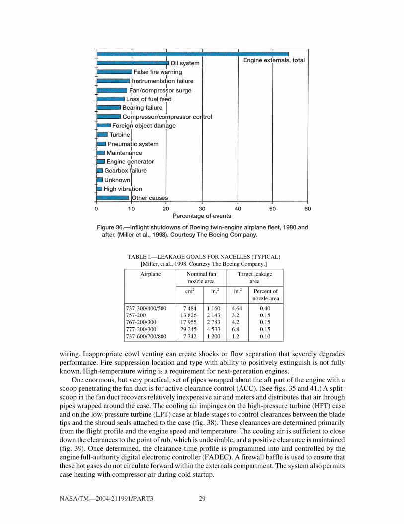
Without engine externals, no smoke, no fire, no thrust—in short, no good. Mike Miller (Boeing“Chief Trouble Shooter,” now retired) presented in some detail the case for engine externals. Milleret al. (1998) writes that “between the engine case and the nacelle cowling there exists a complex spaceoverflowing with pipes, wires, components and challenges (fig. 35). This is the world of engineexternals, a cramped, noisy, hot, high vibration world where the engine controls and engine poweredservices are located. Engine externals are seldom discussed, researched or understood by theaerospace community. This is the realm of the maintenance engineer, airline mechanic and thesystems design engineer.” For one airline the combined estimate of inflight shutdowns amounted toabout 40 percent of their unscheduled maintenance, 80 percent of which related to engine externals(fig. 36). Engine externals account for nearly one-third of the maintenance budget. A look at theBoeing 777 fan duct leakage area of 4387 mm2 (6.8 in.2) per nacelle translates into an operating-empty weight penalty of 9074 N (2040 lb) and a thrust specific fuel consumption increase of0.38 percent. If there were no seals, the penalties would become prohibitive and a 445-N (100-lb) sealweight is quite acceptable.
Leakage areas in older aircraft range to 0.4 percent of fan duct nozzle area with current targetsat an aggressive 0.1 percent (table I). Figure 37 shows that a typical Boeing 777 fan duct seal for onenacelle is nearly 24.7 m (81 ft) long. Miller cites opportunities in good seal designs as well as incooling analysis, fire extinguishing, cowl vent designs, and high-temperature (370 °C; 700 °F)
Figure 35.—Typical Boeing 777 engine with strut and externals installed. (Miller et al., 1998.) Courtesy The Boeing Company.
NASA/TM—2004-211991/PART3 29
wiring. Inappropriate cowl venting can create shocks or flow separation that severely degradesperformance. Fire suppression location and type with ability to positively extinguish is not fullyknown. High-temperature wiring is a requirement for next-generation engines.
One enormous, but very practical, set of pipes wrapped about the aft part of the engine with ascoop penetrating the fan duct is for active clearance control (ACC). (See figs. 35 and 41.) A split-scoop in the fan duct recovers relatively inexpensive air and meters and distributes that air throughpipes wrapped around the case. The cooling air impinges on the high-pressure turbine (HPT) caseand on the low-pressure turbine (LPT) case at blade stages to control clearances between the bladetips and the shroud seals attached to the case (fig. 38). These clearances are determined primarilyfrom the flight profile and the engine speed and temperature. The cooling air is sufficient to closedown the clearances to the point of rub, which is undesirable, and a positive clearance is maintained(fig. 39). Once determined, the clearance-time profile is programmed into and controlled by theengine full-authority digital electronic controller (FADEC). A firewall baffle is used to ensure thatthese hot gases do not circulate forward within the externals compartment. The system also permitscase heating with compressor air during cold startup.
Figure 36.—Inflight shutdowns of Boeing twin-engine airplane fleet, 1980 and after. (Miller et al., 1998). Courtesy The Boeing Company.
100 20 30Percentage of events
40 50 60
Oil system
Turbine
Unknown
Engine externals, total
False fire warning
Instrumentation failure
Fan/compressor surgeLoss of fuel feed
Bearing failure
Compressor/compressor control
Pneumatic system
MaintenanceEngine generator
Gearbox failure
High vibration
Other causes
Foreign object damage
TABLE I.—LEAKAGE GOALS FOR NACELLES (TYPICAL)[Miller, et al., 1998. Courtesy The Boeing Company.]
Nominal fannozzle area
Target leakagearea
Airplane
cm2 in.2 in.2 Percent ofnozzle area
737-300/400/500757-200767-200/300777-200/300737-600/700/800
7 48413 82617 95529 245 7 742
1 1602 1432 7834 5331 200
4.643.24.26.81.2
0.400.150.150.150.10

NASA/TM—2004-211991/PART3 30
Figure 37.—Typical Boeing 777 fan duct seals. (Miller et al., 1998.) Courtesy The Boeing Company.
V or Kgrooveseal
"Bullnose"seal
Thrust reverser slider sealsSliderendseal
Total seal length = 81 ft
8
2
7
6
5
43
1
1
Figure 38.—HPT/LPT active clearance control system. (Halila et al., 1982, modified by fig. 43.)

NASA/TM—2004-211991/PART3 31
Ginn (1998) introduced an experimental effort to characterize engine external flow fields byusing a 20-percent scale model of the engine nacelle, whereas Miller et al. (1998) employed a full-scale mockup model in seal testing. In Ginn’s model all geometric features considered to have aneffect on total pressure loss were considered. The corrected reduced mass flow as a function of stationtotal pressure recovery fraction agreed well with predictions and with full-scale aircraft ground testdata (fig. 40).
Stoner (1998) defines engine externals: “Engine external components include all the fluidcarrying, electron carrying, and support devices that are needed to operate the propulsion system,”are housed between the engine case and the cowl, and interact with the EBU’s or engine buildupcomponents (e.g., inlet, fan cowl, thrust reverser, core cowl, and nozzle) as cited by Miller et al.
Figure 39.—Active clearance control operational profile. (Halila et al., 1982.)
LPT impingementmanifold
Rearframe
HPT impingementmanifold
Fan duct
• Operation – Separate fan-air modulating valves (2) for HPT and LPT – Some opening of clearance at sea-level takeoff (SLTO) – Control by FADEC
Coolingcircuitexhaust
Reduced pressurezone
Modulatingvalve
Scoops
Figure 40.—Predictions compared with full-scale aircraft ground test data. (Ginn, 1998.) Courtesy Lockheed-Martin Company.
1.00
0.99
0.98
0.97
0.96
0.95
0.94
0.93
0.92
Nac
elle
exi
t to
tal p
ress
ure
reco
very
,(P
t nac
–ex/P
t am
b)
0.00 0.50 1.00 1.50 2.00 2.50 3.00 3.50
Prediction
Testrun23456789
Inlet airflow corrected to standard conditions,m Ttamb/Tstd/(Ptamb/Pstd), kg/s· √

NASA/TM—2004-211991/PART3 32
(a)
(b)
Figure 41.—Modern aeronautical gas turbine engine. (a) Left-hand side. (b) Right-hand side. (Stoner, 1998.) Courtesy Pratt & Whitney.

NASA/TM—2004-211991/PART3 33
(1998). There are a myriad of components (fig. 41): hundreds of tubes, maybe 400 hoses and700 brackets, 100 control system components, and a few hundred more EBU and nacelle compo-nents, all secured by thousands of fasteners. There are pumps, heat exchangers, ducts, clamps,sensors, switches, generators, electrical harnesses, and many others without which the engine cannotfunction. The failure of any one of these components to perform its intended function requires amaintenance action, delay of a flight, or in-flight shutdown. The environment in which thesecomponents must function is closely tied to the basic design requirements and life and reliability.Consequently, the components’ operating environment must be understood and controlled by carefuldesign, testing, and field service feedback.
As shown in figures 41 and 42 a look under the cowl of a modern aeronautical gas turbine isbewildering. In addition to thrust the engine must produce the mechanical and electrical powerrequired by the aircraft (the auxiliary power unit (APU) does unload and provide engine support).These engines are hot, vibrate, and function under adverse loadings. Customer requirements withtwo-engine aircraft (e.g., the Boeing 777) for extended operations of more than 1 hour from anadequate airport and over mostly open water are called extended-range, twin-engine operations(“engines turn or passengers swim”, or ETOPS). At entry into service (EIS) ETOPS demands highcomponent reliability, which requires redundancy and/or long life with high reliability, usuallymeaning less than one failure in 1000 components. Engine case temperatures run from ambient toover 650 °C (1200 °F) in the hot (gas generator) section (high-pressure compressor, combustor, high-pressure turbine). This heat is dissipated by conduction, convection, and radiation into the casecooling air derived from the fan. Environmental air and engine power influence the externals’operating temperatures (fig. 43). The flight cycle (fig. 44)—taxi, takeoff, climb, cruise, decent, thrustreversal, taxi, and soak-back—all place high thermomechanical demands on externals (fig. 45).Although the engine rotors are carefully balanced, case-transmitted vibrations are primarily due torotor unbalance or perturbations. Other sources such as flow through ducting, tubes, inlets, pumps,valves, etc., all contribute to the stress cycling and vibration of externals.
Figure 42.—Engine on wing (Boeing 737–600). Courtesy The Boeing Company Commercial Aircraft Division.

NASA/TM—2004-211991/PART3 34
Figure 43.—Engine operating envelope. (Stoner, 1998.) Courtesy Pratt & Whitney.
Maximum flightaltitude
Sea level
–80 –60 –40 –20Ambient air temperature, °C
0 20 40 60
Alti
tud
e
Extreme hot day
Extreme cold day
Standard day
Ground operations,ground start, andtakeoff envelope
Figure 44.—Flight profile. (Stoner, 1998.) Courtesy Pratt & Whitney.
Figure 45.—Material life as function of temperature relation. (Stoner, 1998.) Courtesy Pratt & Whitney.
Log
of
life
N o
r lo
g o
f ho
urs
Low
Hig
h
Low Temperature High

NASA/TM—2004-211991/PART3 35
Aging of an engine usually contributes to increases in dynamic unbalance and forced vibrationsof the externals and raises concern over harmonic resonance. Under dynamic test conditions thecomponent is vibrated along three orthogonal axes at the four most significant resonances, whereresonance is defined as an output/input ratio greater than 2. Input at a mounting point is usually 20 g’sat frequencies to 3 kHz. The location of the gearbox on the case or fan represents a compromise ofthermal demands (forward is cooler) and dynamic demands (rigidly mounted to hot case). In eithercase many brackets are required and many components and brackets experience infant mortality,which is totally unacceptable.
Although gas turbine engine externals are complex and perhaps more familiar, rocket engineexternals are equally complex and require rigorous flight qualification acceptance testing prior toinstallation. Figure 46 features the main components of the space shuttle main engine (SSME)powerhead along with the low- and high-pressure oxygen turbopumps illustrated in the enginecutaway.3,4 This incredible liquid oxygen-hydrogen engine produces 512 950-lb thrust in theabsence of an atmosphere (about 12.3 Mhp) at a vacuum specific impulse of 452 s, gobbling up nearly516 kg/s (1135 lb/s) of propellant. Weighing in at 7480 lb the SSME has a dry thrust/weight ratio of68.6. The thermomechanical extremes range from 20 K for the liquid hydrogen (LH2) fuel systemto 3590 K (6000 °F) combustor temperatures at 20.7 MPa (3000 psia) with a H2/O2 mixture ratioof 6:1. The liquid hydrogen turbomachine runs at 37 000 rpm, delivers 69 000 hp (400 hp/lb) at over43 MPa (6230 psia) with millisecond response times. These machines represent significant sealingchallenges. The liquid oxygen turbomachine runs at 27 000 rpm, delivers 25 000 hp at 29.6 MPa(4300 psia) with a preburner boost pump to over 50.5 MPa (7320 psia) with millisecond response.Under these conditions liquid oxygen is extremely hydrocarbon sensitive, and extreme care is takento ensure hydrocarbon-free operation.
3In some engine circles the turbopumps are considered to be the rocket engine.4Dynamics of the SSME turbopump are discussed in part 2.
Figure 46.—Cutaway of space shuttle main engine (SSME) powerhead featuring high-pressure fuel turbopump (left) and high-pressure oxygen turbopump (right).
LPOTPLPFTP
HPFTP
HPOTP
Gimbal actuatorsupport arm

NASA/TM—2004-211991/PART3 36
Figure 47.—Space shuttle main engine (SSME). (a) Engine externals featuring low- and high-pressure fuel turbopumps, transfer lines, and low-pressure oxidizer turbopump. [Stennis Space Center 94-006-1.jpg; http://nix2.larc.nasa.gov/nix.html (search on, Space Shuttle Main Engine Processing)]. (b) Engine ready for mating to orbiter (red flags are check points and also externals features). [http://science.ksc.nasa.gov/ shuttle/photos/]. (c) Engine in process of mating with orbiter. [http://science.ksc. nasa.gov/shuttle/photos/].
(b)
HPOTP
POGOsystemactuator
LPOTP
LPOTPdischargeduct
(a)
LPFTP
HPFTP
Enginecontroller
POGO systemactuator
LPFTP dischargeduct
LPOTPdischargeduct

NASA/TM—2004-211991/PART3 37
The major differences between a rocket engine and a jet engine include the rocket engine’s shortoperational times, low number of engine cycles, rapid start-stop characteristics with high powerdensity, and high propellant flows. Also the rocket engine has its own oxidizer (cryogenic oxygen)and uses high-performance fuel (cryogenic hydrogen) at extreme thrust and operating conditions(sea level to orbit). In order to achieve these objectives, a myriad of externals (e.g., pipes, wires,valves, seals, instrumentation, controls, and brackets) are required for the engine to function safelyand reliably (fig. 47). The handling, installation, and operational prowess of the SSME is simplystaggering. Figures 47(b) and (c) illustrate the SSME engine being mated to the orbiter from theoxidizer and fuel turbopump sides and can be compared with figures 41 and 35 for the aeronauticalturbomachines. In each orientation, for both engines, engine externals that support and sustain engineoperation encompass all that Miller and Stoner define but are the least understood and researchedfrom a systems point of view until a failure occurs. Then externals receive the attention they deserve.
Additional complexities such as interactive dynamics of the propellant lines, vehicle, andengines (e.g., POGO in rocket engines5 and inlet stall in aeronautical engines) are beyond the scopeof this report but can shut the system down.
5POGO: A problem involving interactive dynamics of vehicle structure and propellant in the feedline column and theengine—analogous to a child on a pogo stick (Fenwick, 1992). Upward engine thrust (g-load) increases turbopumppropellant inlet pressure causing additional propellant flow into the engine, which produces an additional upward forcewith a time delay. If the engine upward force is greater than the downward force at the engine propellant inlet, the engineacts like negative structural damping with potential for POGO. Anti-POGO systems may also require frequency matchingor tuning of the feed system resonance with a structural resonance. In flight tuning and detuning occur naturally aspropellant is consumed, potentially a transient phenomenon. The SSME–POGO suppressor, about the size of a basketball,is teed off the main liquid-oxygen duct just upstream of the high-pressure oxidizer turbopump. A mixture of gaseousoxygen at 478 K (440 °F) and liquid oxygen at 89 K (–300 °F) is continuously bled from the suppressor to control thegas volume and thereby the feed system dynamics, preventing POGO. Then the mixture is reintroduced into the feed lineupstream of the engine so that all the “gas condenses” (Fenwick, 1992).
(c)
Figure 47.—Concluded. (c) Engine in the process of mating with orbiter. [http://science.ksc.nasa.gov/shuttle/photos/].
NASA/TM—2004-211991/PART3 38
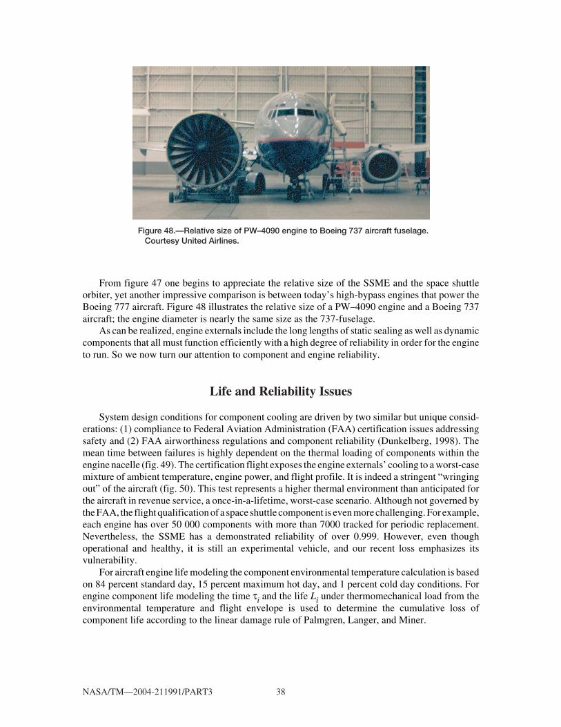
From figure 47 one begins to appreciate the relative size of the SSME and the space shuttleorbiter, yet another impressive comparison is between today’s high-bypass engines that power theBoeing 777 aircraft. Figure 48 illustrates the relative size of a PW–4090 engine and a Boeing 737aircraft; the engine diameter is nearly the same size as the 737-fuselage.
As can be realized, engine externals include the long lengths of static sealing as well as dynamiccomponents that all must function efficiently with a high degree of reliability in order for the engineto run. So we now turn our attention to component and engine reliability.
Life and Reliability Issues
System design conditions for component cooling are driven by two similar but unique consid-erations: (1) compliance to Federal Aviation Administration (FAA) certification issues addressingsafety and (2) FAA airworthiness regulations and component reliability (Dunkelberg, 1998). Themean time between failures is highly dependent on the thermal loading of components within theengine nacelle (fig. 49). The certification flight exposes the engine externals’ cooling to a worst-casemixture of ambient temperature, engine power, and flight profile. It is indeed a stringent “wringingout” of the aircraft (fig. 50). This test represents a higher thermal environment than anticipated forthe aircraft in revenue service, a once-in-a-lifetime, worst-case scenario. Although not governed bythe FAA, the flight qualification of a space shuttle component is even more challenging. For example,each engine has over 50 000 components with more than 7000 tracked for periodic replacement.Nevertheless, the SSME has a demonstrated reliability of over 0.999. However, even thoughoperational and healthy, it is still an experimental vehicle, and our recent loss emphasizes itsvulnerability.
For aircraft engine life modeling the component environmental temperature calculation is basedon 84 percent standard day, 15 percent maximum hot day, and 1 percent cold day conditions. Forengine component life modeling the time τi and the life Li under thermomechanical load from theenvironmental temperature and flight envelope is used to determine the cumulative loss ofcomponent life according to the linear damage rule of Palmgren, Langer, and Miner.
Figure 48.—Relative size of PW–4090 engine to Boeing 737 aircraft fuselage. Courtesy United Airlines.

NASA/TM—2004-211991/PART3 39
R L Ri ii
m
ii
m= ≤
= =∑ ∑τ τ/ / ( )
1 1
1and Life= where 0< 1R
For example, material spends 500 hr at 200 °C (390 °F), point τ1,T1, and 300 hr at 250 °C (450 °F),point τ2,T2. From the material-temperature-life curve (such as fig. 45) at 200 °C the life is 1000 hr(L1,T1) and at 250 °C the life is 600 hr (L2,T2).
Figure 49.—Effect of component temperature on predicted mean time between failures for typical engine-mounted electronic device. (Dunkelberg, 1998.) Courtesy The Boeing Company.
20 deg C
Component temperature
10 000 hrP
red
icte
d M
TB
F
Reliability drivenby parts count orother factors in thisarea
Figure 50.—Temperature of engine-mounted component for certification cooling climb and typical revenue climb corrected to hot day. (Dunkelberg, 1998.) Courtesy The Boeing Company.
Component temperaturefrom typical flight
Elasped time from brake release
Component temperaturefrom certification flight
20 deg C
10 min
Co
mp
one
nt t
emp
erat
ure

NASA/TM—2004-211991/PART3 40
R = 500/1000 + 300/600 = 5/6 and Life = (1000 + 300 )/(5/6) = 1560 hr
Under these conditions 5/6 of the material life is consumed in 1560 hr. If this is unsatisfactory, onemust redesign. This method can sometimes be extended to the components. For ETOPS thecomponents must pass a 3000-cycle engine test and a 1000-cycle flight test, where one cycle is anexcursion between idle and high power.
Zaretsky et al. (2002) applied Weibull-based life and reliability analysis, based on the NASA E3
engine, to rotating engine structures. When limits are placed on stress, temperature, and time for acomponent’s design, the criterion that will define the component’s life and thus the engine’s life willbe either high-cycle or low-cycle fatigue. From the engine manufacturer’s original component lifecalculations, the engine’s life and reliability were determined on the basis of assumed values of eachcomponent’s cumulative life distributions S as represented by a Weibull slope m and characteristiclife Xβ, where S is the probability of survival (0 < S ≤ 1) at load cycle X.
lnln ln ( )1
2S
mX
X=
β
The lives of the HPT disks and blades were also evaluated as a system and individually, where Lsysis the system life where components L1 ...Ln are load cycled X1...Xn.
131
1
2
2L
X
L
X
L
X
Ln
nsys= + + +K ( )
and for components all having the same Weibull slope m,
1 1 1 14
1 2L L L Lm m mnm
sys= + + +K ( )
Engine Life
Knowing the cumulative statistical distribution (Weibull function) of each engine component isa prerequisite to accurately predicting the life and reliability of an entire engine. As the engineWeibull slope increases, the predicted lives decrease. When using table I and equation (5) withmi = 3, 6, 9 (i = 1,3), the predicted engine lives L5 (50 failures in 1000 engines in service) areapproximately 17 000 and 32 000 hr, which depend on the assumed Weibull slope. These livescorrelate with current engine maintenance practices without and with refurbishment, respectively.That is, it can be reasonably anticipated that at one of these time intervals 5 percent of the enginesin service will have been removed for repair or refurbishment for cause.
1 1 1 15
1 2 3L L L Lm m m msys HPTBlade HPT ROT. ST RE
sys= + +
.
( )

NASA/TM—2004-211991/PART3 41
Blade Life
When using equation (6) and table II, the individual HPT blade lives necessary to obtain a bladesystem life L0.1 (one failure in 1000 engines in service) of 9000 hr for Weibull slopes of 3, 6, and 9are 47 391, 20 652, and 15 658 hr, respectively, for a system with n = 146 components.
L nLm m m mblade sys=( ) = ×( )( / ) ( / )
( )1 1
146 9000 6
TABLE II.—E3-ENGINE FLIGHT PROPULSION SYSTEMLIFE BASED ON 1985 TECHNOLOGY AND EXPERIENCE
[From Davis and Stearns, 1985.]
Service life,hr
Total lifewith repair,
hr
CombustorHPT rotating structureHPT bladingRemainder of engine
9 00018 000 9 000--------
18 00036 00018 00036 000
Using these individual HPT blade lives (47 391, 20 652, and 15 658 hr), the values for Xβ are foundfrom equation (1) with S = 0.999. Knowing Xβ, the probability of an individual blade retirement timeX of 18 000 hr, constituting the entire blade life with repair, can then be found from equation (2).Then, reapplying equation (2), X of 18 000 hr can be found. For 1000 engines or 146 000 blades inservice it would be expected that 8, 64, or 512 blades would be removed for cause prior to this timefor Weibull slopes of 3, 6, or 9, respectively.
Turbine Examples
For a design life for each of the two HPT disks having probable points of failure equal to or greaterthan 36 000 hr at a probability of survival of 99.9 percent, the predicted disk system life L0.1 can varyfrom 9408 to 24 911 hr depending on the Weibull slope (3, 6, or 9) assumed. The tabulated stress lifedata of Halila et al. (1982) were used for each disk, and the cross sections were assumed to repeatat 15° segments.
Liu (2001) cites thermomechanical cracking of steam turbine rotors at critical locations as causesof rotor instability that can lead to failure. He suggests that the rotor life limit be set at 0.7Lcreep+fatigue,whereupon shaft dynamics are monitored for crack initiation and propagation. No data are provided.
Need for Data
Within the open literature there is a dearth of data for critical engine components (HPT disk) andfor basic materials. The classic approach to component and engine design has been deterministic. Thedeterministic method assumes that full and certain knowledge exists for the service conditions and

NASA/TM—2004-211991/PART3 42
the material strength. Specific equations define an engine’s operating condition and are coupled withexperience-based safety factors. Variations with loading, such as platform and disk temperature andthermal gradients, can have a significant effect on component reliability. The Weibull-based analysisaddresses these issues of component life and reliability (Zaretsky et al., 2002).
Summary
Altering engine sealing, particularly on the high-pressure spool or high-pressure pumps of thesystem, alters the entire engine dynamics. Knowing how to utilize these changes becomes acompany’s competitive edge. Cavity sealing of a turbomachine pump, compressor, or turbine iscomplex and has a significant effect on component and engine performance. Several numerical tools(e.g., NASA-developed INDSEAL, SCISEAL, and ADPAC) are available to help guide the designerand experimenter. And in time data will emerge to more rigorously validate these codes, from rigexperiments to results from field operations. Now, however, the numerical tools cited are applicable,but the validation data are sparse.
As interesting as cavity, rim, platform, and tip flows are, most design codes find it necessary tominimize computations and represent these complex flow passages with simple models. The cost andcomplexity of including local geometric details necessary to capture these flows for a fan,compressor, or turbine become prohibitive. Nevertheless, in the details are challenges and opportu-nities for engine performance improvements. However, most funding and experiments are in supportof design code validation and implementation.
Gas turbine engine externals inhabit the space between the engine case and the nacelle cowling.Rocket engine externals occupy a similar space within the confines of the aft-fairing frame. Withinthat space, overflowing with pipes, wires, and fire-extinguishing components, are challenges andopportunities for sealing long lengths of cowling and improving flow dynamics, cooling and fluiddistribution, and dynamic components. All must function efficiently with a high degree of reliabilityin order for the engine to run.
Within the open literature there is a dearth of statistically significant data for critical enginecomponents (e.g., the high-pressure turbine disk) and for basic materials. The classic approach tocomponent and engine design has been deterministic. The deterministic method assumes that full andcertain knowledge exists for the service conditions and the material strength. Specific equationsdefine an engine’s operating condition and are coupled with experience-based safety factors. In the“hands” of an experienced and seasoned designer or engineer, these equations are adequate.However, variations with loading can have a significant effect on component reliability. Stoner andZaretsky addressed the reliability issues with Weibull-based analysis potentially applicable to theengine, but without validation data they are just studies. These variations and deficits in statisticaldatabases require immediate attention.
References
Adamczyk, J.J., Celestina, M.L., and Greitzer, E.M. (1993) The Role of Tip Clearance in High-SpeedFan Stall, J. Turbomachinery, vol. 115, no. 1, pp. 29–39.
Allcock, D.C.J., Ivey, P.C., and Turner, J.R. (2002) Abradable Stator Gas Turbine Labyrinth Seals:Part 2, Numerical Modeling of Differing Seal Geometries and the Construction of a SecondGeneration Design Tool. AIAA Paper 2002–3937.
NASA/TM—2004-211991/PART3 43
Ameri, A.A., Steinthorsson, E., and Rigby, D.L. (1999) Effects of Tip Clearance and Casing Recesson Heat Transfer and Stage Efficiency in Axial Turbines. Transactions ASME, Journal ofTurbomachinery, Vol. 121, Oct., pp. 683–693.
Ameri, A.A. and Bunker (2000) Heat Transfer and Flow on the First-Stage Blade Tip of a PowerGeneration Gas Turbine: Part 2 Simulation Results, Transactions ASME, Journal of Turbomachinery,Vol. 122, April, pp. 272–277.
Athavale, M.M., Przekwas, A.J., and Hendricks, R.C. (1992) A Numerical Study of the Flow-Fieldin Enclosed Turbine Disk-Cavities in Gas Turbine Engines, Proceedings of the 4th InternationalSymposium on Transport Phenomena and Dynamics of Rotating Machinery (ISROMAC–4).
Athavale, M.M., Przekwas, A.J., and Hendricks, R.C. (1993) Driven Cavity Simulation ofTurbomachine Blade Flows With Vortex Control, AIAA Paper 93–0390.
Athavale, M.M., Przekwas, A.J., Hendricks, R.C., and Steinetz, B.M. (1995) Numerical Analysis ofIntra-Cavity and Power-Stream Flow Interaction in Multiple Gas-Turbine Disk-Cavities, ASMEPaper 95–GT–325.
Athavale, M.M., Przekwas, A.J., Hendricks, R.C., and Steinetz, B.M. (1997) Development of aCoupled, Transient Simulation Methodology for Interaction Between Primary and SecondaryFlowpaths in Gas Turbine Engines, AIAA Paper 97–2727.
Athavale, M.M., Przekwas, A.J., Hendricks, R.C., and Steinetz, B.M. (1998) Coupled TransientSimulations of the Interaction Between Power and Secondary Flowpaths in Gas Turbines, AIAAPaper 98–3290.
Athavale, M.M., Ho, Y.H., and Przekwas, A.J. (1999) Analysis of Coupled Seals, Secondary andPowerstream Flow Fields in Aircraft and Aerospace Turbomachines, Final Report, NASA ContractNAS3–27392, December.
Athavale, M.M., Steinetz, B.M., and Hendricks, R.C. (2001) Gas Turbine Primary-Secondary FlowPath Interaction: Transient, Coupled Simulation and Comparison With Experiments, AIAA Paper2001–3627.
Bilwakesh, K.R. and Koch, C.C. (1972) Evaluation of Range and Distortion Tolerance for HighMach Number Transonic Fan Stages, Task 2: Performance of a 1500-Foot-Per-Second Tip SpeedTransonic Fan Stage With Variable Geometry Inlet Guide Vanes and Stator, NASA CR–72880.
Campbell, D.A. (1978) Gas Turbine Disk Sealing System Design, AGARD–CP–237 (AGARD–AR–123), Paper 18.
Chen, J.P. (1991) Unsteady Three-Dimensional Thin-Layer Navier-Stokes Solutions forTurbomachinery in Transonic Flows, Ph.D. Thesis, Department of Aerospace Engineering, Missis-sippi State University, Dec.
Chew, J.W. (1988) Predictions of Flow in Rotating Disk Systems Using the k-ε Turbulence Model,ASME Paper 88–GT–229.
NASA/TM—2004-211991/PART3 44
Chew, J.W., Green, T., and Turner, A.B. (1992) Rim Sealing of Rotor-Stator Wheelspaces in thePresence of External Flow, J. Turbomachinery, vol. 114, pp. 426–432.
Copenhaver, W.W., Mayhew, E.R., Hah, C., and Wadia, A.R. (1996) The Effect of Tip Clearanceon a Swept Transonic Compressor Rotor, J. Turbomachinery, vol. 118, Apr., pp. 230–239.
Davis, D.Y. and Stearns, E.M. (1985) Energy Efficient Engine Flight Propulsion System FinalDesign and Analysis, NASA CR–168219.
Dunkelberg, K. (1998) Commercial Airplane Nacelle Component (Engine Externals) Certificationand Typical Temperature Exposure, Proceedings of the 7th International Symposium on TransportPhenomena and Dynamics of Rotating Machinery (ISROMAC–7). (See also NASA AdvancedSubsonic Technology (AST) 028, 1998.)
Feiereisen, J.M., Paolillo, R.E., and Wagner, J. (2000) UTRC Turbine Rim Seal Ingestion andPlatform Cooling Experiments, AIAA Paper 2000–3371, July.
Fenwick, J. (1992) POGO, Rocketdyne’s Engineering Journal of Power Technology, http://www.engineering at boeing.com/articles/pogo.jsp.
Ginn, K.B. (1998) An Experimental Approach for Engine Nacelle Flowfield Characterization,Proceedings of the 7th International Symposium on Transport Phenomena and Dynamics of RotatingMachinery (ISROMAC–7).
Graber, D.J., Daniels, W.A., and Johnson, B.V. (1987) Disk Pumping Test, AFWAL–TR–87–2050.
Halila, E.E., Lenahan, D.T., and Thomas, T.T. (1982) Energy Efficient Engine High PressureTurbine Test Hardware: Detailed Design Report, NASA CR–167955.
Hall, E.J. and Delaney, R.A. (1993a) Investigation of Advanced Counterrotation Blade Configura-tion Concepts for High Speed Turboprop Systems, Task 5—Unsteady Counterrotation DuctedPropfan Analysis Computer Program User’s Manual, NASA CR–187125.
Hall, E.J. and Delaney, R.A. (1993b) Investigation of Advanced Counterrotation Blade Configura-tion Concepts for High Speed Turboprop Systems, Task 5—Unsteady Counterrotation DuctedPropfan Analysis Final Report, NASA CR–187126.
Hall, E.J. and Delaney, R.A. (1995) Investigation of Advanced Counterrotation Blade ConfigurationConcepts for High Speed Turboprop Systems, Task 7—ADPAC User’s Manual, NASA ContractNAS3–25270, NASA CR–195472.
Heidegger, N.J., Hall, E.J., and Delaney, R.A. (1996) Parameterized Study of High-Speed Compres-sor Seal Cavity Flow, NASA CR–198504. (Also AIAA Paper 96–2807, 1996.)
Hendricks, R.C., Steinetz, B.M., Athavale, M.M., Przekwas, A.J., Braun, M.J., Dozozo, M.I., Choy,F.K., Kudriavtsev, V.V., Mullen, R.L., and von Pragenau, G.L. (1995) Interactive Developments ofSeals, Bearings, and Secondary Flow Systems With the Power Stream, Int. J. Rotating Machinery,vol. 1, no. 3–4, pp. 153–185.
NASA/TM—2004-211991/PART3 45
Ho, Y.H., Athavale, M.M., Forry, J.M., Hendricks, R.C., and Steinetz, B.M. (1996) NumericalSimulation of Secondary Flow in Gas Turbine Disc Cavities, Including Conjugate Heat Transfer,ASME Paper 96–GT–67.
Janus, J.M. (1989) Advanced 3–D CFD Algorithm for Turbomachinery, Ph.D. Thesis, Departmentof Aerospace Engineering, Mississippi State University, May.
Janus, J.M. and Horstman, H.Z. (1992) Unsteady Flow-Field Simulation of Ducted Prop-FanConfigurations, AIAA Paper 92–0521.
Johnson, B.V., Daniels, W.A., Kaweki, E.J., and Martin, R.J. (1991) Compressor Drum Aerody-namic Experiments With Coolant Injected at Selected Locations, J. Turbomachinery, vol. 113, pp.272–280.
Johnson, B.V., Mack, G.J., Paolillo, R.E., and Daniels, W.A. (1994) Turbine Rim Seal Gas Path FlowIngestion Mechanisms, AIAA Paper 94–2703.
Johnsen, I.A. and Bullock, R.O., eds. (1965) Aerodynamic Design of Axial-Flow Compressors(Revised), NASA SP–36. (Supersedes declassified NACA Memorandums E56B03, E56B03a, andE56B03b, 1956.)
Lakshminarayana, B. (1996), Fluid Dynamics and Heat Transfer of Turbomachinery, John Wiley &Sons, New York.
Liu, K.M. (2001) Life Begins at 70, Proceedings of the 1st International Symposium on StabilityControl of Rotating Machinery (ISCORMA–1).
Miller, M., Colehour, J., and Dunkelberg, K. (1998) Engine Case Externals, Challenges andOpportunities, Proceedings of the 7th International Symposium on Transport Phenomena andDynamics of Rotating Machinery (ISROMAC–7). (See also NASA CP–10198, 1996.)
NASA Conference Publications—Hendricks, R.C., Liang, A.D., and Steinetz, B.M., eds., SealsCode Development and Seal and Secondary Air Systems Workshops, NASA CP–10124 (1992);NASA CP–10136 (1993); NASA CP–10181 (1995); NASA CP–10198 (1996); NASA CP–208916(1998); NASA CP–210472 (2000); NASA CP–211208 (2001).
PDE: http://www.grc.nasa.gov/WWW/AERO/base/pdet.htm
Smout, P.D., Chew, J.W., and Childs, P.R.N. (2002) ICAS–GT: A European Collaborative ResearchProgramme on Internal Cooling Air Systems for Gas Turbines, Paper GT–2002–30479.
Song, S.J. and Cho, S.H. (2000) Nonuniform Flow in a Compressor Due to Asymmetric TipClearance, J. Turbomachinery, vol. 122, Oct., pp. 751–760.
Stoner, B.L. (1998) The Importance of Engine Externals’ Health, Proceedings of the 7th Interna-tional Symposium on Transport Phenomena and Dynamics of Rotating Machinery (ISROMAC–7).
Strazisar, A.J., Wood, J.R., Hathaway, A.D., and Suder, K.L. (1989) Laser Anemometer Measure-ments in a Transonic Axial-Flow Fan Rotor, NASA TP–2879.

NASA/TM—2004-211991/PART3 46
Strazisar, A.J. (1985) Investigation of Flow Phenomena in a Transonic Fan Rotor Using LaserAnemometry, J. Engineering for Gas Turbine and Power, vol. 107, Apr., pp. 427–435.
Teramachi, K., Manabe, T., Yanagidani, N., and Fujimura, T. (2002) Effect of Geometry and FinOverlap on Sealing Performance of Rims Seals, AIAA Paper 2002–3938.
Van Zante, D.E., Stazisar, A.J., Wood, J.R., Hathaway, M.D., and Okiishi, T.H. (1999) Recommen-dations for Achieving Accurate Numerical Simulation of Tip Clearance Flows in TransonicCompressor Rotors, Paper 99–GT–390.
Virr, G.P., Chew, J.W., and Coupland, J. (1994) Application of Computational Fluid Dynamics toTurbine Disc Cavities, J. Turbomachinery, vol. 116, pp. 701–708.
Wellborn, S.R. and Okiishi, T.H. (1996) Effects of Shroud Stator Cavity Flows on Multistage AxialCompressor Performance, NASA CR–198536.
Wellborn, S.R. and Okiishi, T.H. (1999) The Influence of Shrouded Stator Cavity Flows onMultistage Compressor Performance, J. Turbomachinery, vol. 121, no. 3, pp. 486–498.
Wilson, J., Hendricks, R.C., Wu, T., and Flower, R. (1997) Bidirectional Brush Seals, NASA TM–107351. (http://www.grc.nasa.gov/WWW/cdtb/projects/waverotor/index.html).
Zaretsky, E.V., Hendricks, R.C., and Soditus, S. (2002) Weibull-Based Design Methodology forRotating Aircraft Engine Structures, Proceedings of the 9th International Symposium on TransportPhenomena and Dynamics of Rotating Machinery (ISROMAC–9).

NASA/TM—2004-211991/PART3 47
Appendix—Symbols
Nomenclature for figures 24 to 34:c clearance gapLE leading edgem mass flow rateM Mach numberP pressurePS pressure sideSS suction siderω rotor speedr rotor radiust blade thicknessT temperatureTE trailing edger
U rotor (moving coordinate) velocity (Vθ = rω)rV absolute (stationary coordinate) velocityrVR relative (moving coordinate) velocity
Vz axial coordinate velocityVθ circumferential coordinate velocityZ axial coordinateθ circumferential coordinateρ fluid density
Subscripts:L lowH highs statict total
Nomenclature for life and reliability issues:L0.1 1 failure in 1000 componentsL1, 2 …, n life of components 1, 2 …, nL5 50 failures in 1000 componentsLblade blade lifeLi life of material at temperature Ti based on test dataLsys system life based on L1, 2 …, nm Weibull slopen number of system componentsR portion of life consumed at operating conditionsS probability of survivalX load cycles or timeXβ Weibull characteristic lifeτi time spent at temperature Ti
Subscripts:HPT Blade high-pressure-turbine bladeHPT ROT.ST. high-pressure rotating structureRE remainder of engine

This publication is available from the NASA Center for AeroSpace Information, 301–621–0390.
REPORT DOCUMENTATION PAGE
2. REPORT DATE
19. SECURITY CLASSIFICATION OF ABSTRACT
18. SECURITY CLASSIFICATION OF THIS PAGE
Public reporting burden for this collection of information is estimated to average 1 hour per response, including the time for reviewing instructions, searching existing data sources,gathering and maintaining the data needed, and completing and reviewing the collection of information. Send comments regarding this burden estimate or any other aspect of thiscollection of information, including suggestions for reducing this burden, to Washington Headquarters Services, Directorate for Information Operations and Reports, 1215 JeffersonDavis Highway, Suite 1204, Arlington, VA 22202-4302, and to the Office of Management and Budget, Paperwork Reduction Project (0704-0188), Washington, DC 20503.
NSN 7540-01-280-5500 Standard Form 298 (Rev. 2-89)Prescribed by ANSI Std. Z39-18298-102
Form Approved
OMB No. 0704-0188
12b. DISTRIBUTION CODE
8. PERFORMING ORGANIZATION REPORT NUMBER
5. FUNDING NUMBERS
3. REPORT TYPE AND DATES COVERED
4. TITLE AND SUBTITLE
6. AUTHOR(S)
7. PERFORMING ORGANIZATION NAME(S) AND ADDRESS(ES)
11. SUPPLEMENTARY NOTES
12a. DISTRIBUTION/AVAILABILITY STATEMENT
13. ABSTRACT (Maximum 200 words)
14. SUBJECT TERMS
17. SECURITY CLASSIFICATION OF REPORT
16. PRICE CODE
15. NUMBER OF PAGES
20. LIMITATION OF ABSTRACT
Unclassified Unclassified
Technical Memorandum
Unclassified
National Aeronautics and Space AdministrationJohn H. Glenn Research Center at Lewis FieldCleveland, Ohio 44135–3191
1. AGENCY USE ONLY (Leave blank)
10. SPONSORING/MONITORING AGENCY REPORT NUMBER
9. SPONSORING/MONITORING AGENCY NAME(S) AND ADDRESS(ES)
National Aeronautics and Space AdministrationWashington, DC 20546–0001
Available electronically at http://gltrs.grc.nasa.gov
July 2004
NASA TM—2004-211991-PART3
E–13662–3
Cost Center 2250000013
53
Turbomachine Sealing and Secondary FlowsPart 3—Review of Power-Stream Support, Unsteady Flow Systems, Seal and Disk Cavity Flows,Engine Externals, and Life and Reliability Issues
R.C. Hendricks, B.M. Steinetz, E.V. Zaretsky, M.M. Athavale, and A.J. Przekwas
Turbomachine; Seals; Secondary flow; Engine externals; Component life
Unclassified -UnlimitedSubject Categories: 01, 07, 20, and 37 Distribution: Nonstandard
Portions of this material were presented at the Second International Symposium on Stability Control of RotatingMachinery sponsored by Bently Pressurized Bearing Company, Gdansk, Poland, August 4–8, 2003. R.C. Hendricks,B.M. Steinetz, and E.V. Zaretsky, NASA Glenn Research Center; and M.M. Athavale and A.J. Przekwas, CFD ResearchCorporation, Huntsville, Alabama 35805. Responsible person, R.C. Hendricks, organization code 5000, 216–977–7507.
The issues and components supporting the engine power stream are reviewed. It is essential that companies pay closeattention to engine sealing issues, particularly on the high-pressure spool or high-pressure pumps. Small changes in thesesystems are reflected throughout the entire engine. Although cavity, platform, and tip sealing are complex and have asignificant effect on component and engine performance, computational tools (e.g., NASA-developed INDSEAL,SCISEAL, and ADPAC) are available to help guide the designer and the experimenter. Gas turbine engine and rocketengine externals must all function efficiently with a high degree of reliability in order for the engine to run but oftenreceive little attention until they malfunction. Within the open literature statistically significant data for critical enginecomponents are virtually nonexistent; the classic approach is deterministic. Studies show that variations with loading canhave a significant effect on component performance and life. Without validation data they are just studies. These varia-tions and deficits in statistical databases require immediate attention.

