turner - bharat skillspractical book, test and assignment book, instructor guide, audio visual aid...
TRANSCRIPT

(i)
NATIONAL INSTRUCTIONALMEDIA INSTITUTE, CHENNAI
Post Box No. 3142, CTI Campus, Guindy, Chennai - 600 032
DIRECTORATE GENERAL OF TRAININGMINISTRY OF SKILL DEVELOPMENT & ENTREPRENEURSHIP
GOVERNMENT OF INDIA
TRADE PRACTICAL
SECTOR: Production & Manufacturing
TURNER
4th Semester
NSQF LEVEL - 5
Copyright @ NIMI Not to be Republished

(ii)
Sector : TurnerDuration : 2 - YearsTrade : Turner 4th Semester - Trade Practical - NSQF level 5
Copyright© 2018 National Instructional Media Institute, Chennai
First Edition : December 2018 Copies : 1,000
Rs.155/-
All rights reserved.
No part of this publication can be reproduced or transmitted in any form or by any means, electronic or mechanical,including photocopy, recording or any information storage and retrieval system, without permission in writing from theNational Instructional Media Institute, Chennai.
Published by:
NATIONAL INSTRUCTIONAL MEDIA INSTITUTEP. B. No.3142, CTI Campus, Guindy Industrial Estate,
Guindy, Chennai - 600 032.Phone : 044 - 2250 0248, 2250 0657, 2250 2421
Fax : 91 - 44 - 2250 0791email : [email protected], [email protected]
Website: www.nimi.gov.in
Copyright @ NIMI Not to be Republished

(iii)
FOREWORD
The Government of India has set an ambitious target of imparting skills to 30 crores people, one out of everyfour Indians, by 2020 to help them secure jobs as part of the National Skills Development Policy. IndustrialTraining Institutes (ITIs) play a vital role in this process especially in terms of providing skilled manpower.Keeping this in mind, and for providing the current industry relevant skill training to Trainees, ITI syllabushas been recently updated with the help of Mentor Councils comprising various stakeholder's viz. Industries,Entrepreneurs, Academicians and representatives from ITIs.
The National Instructional Media Institute (NIMI), Chennai has now come up with instructional material tosuit the revised curriculum for Turner 4th Semester Trade Practical NSQF Level - 5 in Production &Manufacturing Sector under Semester Pattern. The NSQF Level - 5 Trade Theory will help the traineesto get an international equivalency standard where their skill proficiency and competency will be dulyrecognized across the globe and this will also increase the scope of recognition of prior learning. NSQFLevel - 5 trainees will also get the opportunities to promote life long learning and skill development. I have nodoubt that with NSQF Level - 5 the trainers and trainees of ITIs, and all stakeholders will derive maximumbenefits from these IMPs and that NIMI's effort will go a long way in improving the quality of Vocationaltraining in the country.
The Executive Director & Staff of NIMI and members of Media Development Committee deserve appreciationfor their contribution in bringing out this publication.
Jai Hind
RAJESH AGGARWALDirector General/ Addl.Secretary
Ministry of Skill Development & Entrepreneurship,Government of India.
New Delhi - 110 001
Copyright @ NIMI Not to be Republished

(iv)
PREFACE
The National Instructional Media Institute (NIMI) was established in 1986 at Chennai by then DirectorateGeneral of Employment and Training (D.G.E & T), Ministry of Labour and Employment, (now under DirectorateGeneral of Training, Ministry of Skill Development and Entrepreneurship) Government of India, with technicalassistance from the Govt. of the Federal Republic of Germany. The prime objective of this institute is todevelop and provide instructional materials for various trades as per the prescribed syllabi under the Craftsmanand Apprenticeship Training Schemes.
The instructional materials are created keeping in mind, the main objective of Vocational Training underNCVT/NAC in India, which is to help an individual to master skills to do a job. The instructional materialsare generated in the form of Instructional Media Packages (IMPs). An IMP consists of Theory book,Practical book, Test and Assignment book, Instructor Guide, Audio Visual Aid (Wall charts andTransparencies) and other support materials.
The trade practical book consists of series of exercises to be completed by the trainees in the workshop.These exercises are designed to ensure that all the skills in the prescribed syllabus are covered. Thetrade theory book provides related theoretical knowledge required to enable the trainee to do a job. Thetest and assignments will enable the instructor to give assignments for the evaluation of the performanceof a trainee. The wall charts and transparencies are unique, as they not only help the instructor to effectivelypresent a topic but also help him to assess the trainee's understanding. The instructor guide enables theinstructor to plan his schedule of instruction, plan the raw material requirements, day to day lessons anddemonstrations.
IMPs also deals with the complex skills required to be developed for effective team work. Necessary carehas also been taken to include important skill areas of allied trades as prescribed in the syllabus.
The availability of a complete Instructional Media Package in an institute helps both the trainer andmanagement to impart effective training.
The IMPs are the outcome of collective efforts of the staff members of NIMI and the members of theMedia Development Committees specially drawn from Public and Private sector industries, various traininginstitutes under the Directorate General of Training (DGT), Government and Private ITIs.
NIMI would like to take this opportunity to convey sincere thanks to the Directors of Employment & Trainingof various State Governments, Training Departments of Industries both in the Public and Private sectors,Officers of DGT and DGT field institutes, proof readers, individual media developers and coordinators, butfor whose active support NIMI would not have been able to bring out this materials.
R. P. DHINGRAChennai - 600 032 EXECUTIVE DIRECTOR
Copyright @ NIMI Not to be Republished

(v)
ACKNOWLEDGEMENT
National Instructional Media Institute (NIMI) sincerely acknowledges with thanks for the co-operation and
contribution extended by the following Media Developers and their sponsoring organisations to bring out this
Instructional Material (Trade Practical) for the trade of Turner under the Production & Manufacturing sector
for ITI.
MEDIA DEVELOPMENT COMMITTEE MEMBERS
Shri. Natarajan _ Training OfficerGovt. I.T.I SalemTamil Nadu
Shri. Dayala moorthy _ Assistant Training officerGovt. I.T.I VelloreTamil Nadu
Shri. M. Sampath _ Training Officer (Retd)MDC MemberChennai - 600032
Shri. R. Purushottaman _ Assistant DirectorMSME, ChennaiTamilnadu
Shri. T. Janakiram _ Assistant Director RtdGovt. RIC Chennai (N)Tamil Nadu
Shri. R. Sekaran _ JTO RtdGovt. I.T.I AmbatturTamil Nadu
NIMI CO-ORDIANTORS
Shri. K. Srinivasa Rao _ Joint DirectorNIMI, Chennai - 32
Shri. N. Ashfaq Ahmed _ Assitant Manager,Co-ordinator, NIMI, Chennai - 32
NIMI records its appreciation for the Data Entry, CAD, DTP operators for their excellent and devoted services inthe process of development of this Instructional Material.
NIMI also acknowledges with thanks the invaluable efforts rendered by all other NIMI staff who have contributed towardsthe development of this Instructional Material.
NIMI is also grateful to everyone who has directly or indirectly helped in developing this Instructional Material.
Copyright @ NIMI Not to be Republished

(vi)
INTRODUCTION
TRADE THEORY
The manual of trade theory consists of theorectical information for the fourth Semester couse of the TurnerTrade. The contents are sequenced accoring to the practical exercise contained in the manual on Tradepractical. Attempt has been made to relate the theortical aspects with the skill covered in each exercise to theextent possible. This co-relation is maintained to help the trainees to develop the perceptional capabilities forperforming the skills.
The Trade Theory has to be taught and learnt along with the corresponding exercise contained in the manualon trade practical. The indicating about the corresponding practical exercise are given in every sheet of thismanual.
It will be preferable to teach/learn the trade theory connected to each exercise atleast one class beforeperforming the related skills in the shop floor. The trade theory is to be treated as an integrated part of eachexercise.
The material is not the purpose of self learning and should be considered as supplementary to class roominstruction.
TRADE PRACTICAL
The trade practical manual is intented to be used in workshop . It consists of a series of practical exercies tobe completed by the trainees during the fourth Semester course of the Turner trade supplemented andsupported by instructions/ informations to assist in performing the exercises. These exercises are designedto ensure that all the skills in the prescribed syllabus are covered.
The manual is divided into six modules. The distribution of time for the practical in the six modules are givenbelow.
Module 1 Introduction to CNC 25 HrsModule 2 CNC lathe operation 75 HrsModule 3 Tool setting and data input 75 Hrs
Module 4 Programme and Simulation 75 Hrs
Module 5 CNC Turning operations 75 Hrs
Module 6 Advance Turning 200Hrs
Total 525 Hrs
The skill training in the computer lab is planned through a series of practical exercises centred around somepractical project. However, there are few instance where the individual exercise does not form a part of project.
While developing the practical manual a sincere effort was made to prepare each exercise which will be easyto understand and carry out even by below average traninee. However the development team accept that thereif a scope for further improvement. NIMI, looks forward to the suggestions from the experienced training facultyfor improving the manual.
Copyright @ NIMI Not to be Republished

(vii)
CONTENTS
Exercise No. Title of the Exercise Page No.
Module 1: Introduction to CNC4.1.111 Personal and CNC machine safety 1
4.1.112 Identify CNC machines and CNC consoles 3
4.1.113 Demonstration of CNC lathe machine and its parts 6
4.1.114 Working of CNC machine by using multimedia based simulator 8
4.1.115 Identify machine over travel limits & emergency stop 10
Module 2: CNC Lathe Operation
4.2.116 Conduct a preliminary check of readiness of the CNC turning centre. 12
4.2.117 Identification of safety switches and interlocking of DIH mode. 13
4.2.118 Machine Starting and operating in Reference point, JOG and incremental mode 15
4.2.119 Check CNC part programming with simple exercises and using variousprogramming code. 20
4.2.120 Check the programme in simulation on machine or practice in simulationsoftware in respective control system 24
4.2.121 Absolute and incremental programming assignment by simulation 26
4.2.122 Linear interpolation and circular interpolation assignments and simulationon software 28
Module 3: Tool setting and Data Input
4.3.123 Perform work and tool setting and tool set up and live tool set up. 30
4.3.124 Carryout Jaw adjustments according to diameter and tooling setup on turret 31
4.3.125 CNC turning centre operation in various modes (Jog, Edit, MDI, single blockand Auto mode) 33
4.3.126 Programme entry in CNC lathe 35
4.3.127 Set the tool offsets, entry of TNRC and orientation (FANUC Control) 36
4.3.128 Conduct work offset measurement and tool offset measurements andentry in CNC control 39
4.3.129 Make tool nose radius and tool orientation entry in CNC control 42
4.3.130 Jaw removal and mounting on CNC lathe 45
4.3.131 Manual Data Input (MDI) and MPG mode operation and checking up zerooffset and tool offset. 46
Module 4: Programme and Simulation
4.4.132 Programme checking by dry run single block mode 47
4.4.133 Checking finish size by oversizing through tool offsets 49
4.4.134 Part programme preparation, simulation and automatic mode execution 51
4.4.135 Part programme preparation, for turning with chamfering & radius turningwith TNRC 53
Copyright @ NIMI Not to be Republished

(viii)
4.4.136 Part programme preparations with contours with TNRC and simulation 56
4.4.137 Machining parts on CNC lathe with parallel, taper, step, radius , turning,grooving and threading 58
4.4.138 Carryout drilling/boring cycles in CNC turning 61
Module 5: CNC Turning Operations
4.5.139 Geometry wear corrections and offset corrections 64
4.5.140 Produce components on CNC machine involving different “Programmingfor turning OD, ID grooving operation, turning operation” 66
4.5.141 Produce components by involving turning operations and part programme 69
4.5.142 Part off : Part programme in CNC machine 72
4.5.143 Produce job involving profile turning, threading, taper & boring 74
4.5.144 Demo on machine on Bar feeding system (video) 78
4.5.145 DNC system set up (Optional) 80
4.5.146 Run the machine on DNC mode (Optional) 81
4.5.147 CAM programme execution (optional) 83
4.5.148 Data Input-output on CNC machine 85
Module 6 : Advance Turning
4.6.149 Thread on taper surface (Vee form) 86
4.6.150 Manufacturing and Assembly of screw jack by performing differentlathe operations. 88
4.6.151 Prepare different type of documentations and methods of recording information 95
4.6.152 Turn Bevel gear blank 110
4.6.153 Reading a part drawing and make a process plan (to make arbor withclamping Hexagonal nut) 116
4.6.154 Practice of special operation on a lathe/worm cutting 118
4.6.155 Boring on the lathe using soft jaws to make bush with Standard collar 120
4.6.156 Make a Arbor support Bush (Proof machining) 122
Exercise No. Title of the Exercise Page No.
Copyright @ NIMI Not to be Republished

(ix)
LEARNING / ASSESSABLE OUTCOME
On completion of this book you shall be able to
• Set (Both job and tool) CNC turning centre and produce componentsas per drawing by preparing part programme.
• Manufacture and assemble components to produce utility itemsby performing different operations and observing principle ofinterchangability and check functionality item (screw jack, vicespindle, box nut, marking block, drill chuck, collet chuck etc, bydifferent operation).
• Threading (Square thread) BSW, ACME, Metric, thread on taper,different boring operations.
• Make a process plan to produce components by performingspecial operations on lathe and check for accuracy.
• Perform special operation in CNC lathe worm shaft cutting, boring,threading etc.,.
Copyright @ NIMI Not to be Republished

(x)
SYLLABUS
Fourth Semester Duration: Six Month
WeekNo.
79
80-82
Ref. LearningOutcome
• Set (both job andtool) CNC turncentre and producecomponents as perdrawing bypreparing partprogramme.
-do-
Professional Skills (Trade Practical) with Indicative hours
111. Personal and CNC machineSafety: Safe handling of tools, equipment and CNCmachine. (2 hrs.)
112. Identify CNC machine, CNC console. (5 hrs.)
113. Demonstration of CNC lathe machine and its parts - bed, spindle motor and drive, chuck, tailstock, turret, axes motor and ball screws, guide ways, LM guides, console, control switches,coolant system, hydraulic system, chip conveyor, steady rest. (7 hrs.)
114. Working of parts explained using Multimedia based simulator for CNC parts shown on machine. (6 hrs.)
115. Identify machine over travel limits and emergency stop. (1 hrs.)
116. Conduct a preliminary check of the readiness of the CNC turning centre viz., cleanliness of machine, referencing – zero return, functioning of lubrication, coolant level, correct working of sub-system. (2 hrs.)
117. Identification of safety switches and interlocking of DIH modes. (1 hrs.)
118. Machine starting & operating in Reference Point, JOG and Incremental Modes. (12 hrs.)
119. Check CNC part programming with simple exercises and using various programming codes and words. (12 hrs.)
120. Check the programme simulation on machine OR practice in simulation software in respective control system. (12 hrs.)
Professional Knowledge(Trade Theory)
CNC technology basics:Difference between CNC andconventional lathes.Advantages and disadvantages ofCNC machines over conventionalmachines.Machine model, control systemand specification.Axes convention of CNC machine- Machine axes identification forCNC turncentre.Importance of feedback devicesfor CNC control.Concept of Co-ordinate geometry,concept of machine axis.
Programming – sequence, formats,different codes and words.Co-ordinate system points andsimulations.Work-piece zero points and ISO/DIN G and M codes for CNC.Different types of programmingtechniques of CNC machine.Describe the stock removal cycle inCNC turning for OD / ID operation.L/H and R/H tool relation on speed.Describe CNC interpolation, openand close loop control systems. Co-ordinate systems and Points.Program execution in differentmodes like manual, single blockand auto.Absolute and incrementalprogramming.Canned cycles.Cutting parameters- cutting speed,feed rate , depth of cut, constantsurface speed, limiting spindlespeed, tool wear,tool life, relative effect of eachcutting parameter on tool life.
Copyright @ NIMI Not to be Republished

(xi)
83-85
86-88
-do-
-do-
121. Absolute and incremental programming assignments and simulations. (12 hrs.)
122. Linear interpolation, and Circular interpolation assignments and simulations on soft ware. (24hrs.)
123. Perform Work and tool setting:- Job zero/work coordinate system and tool setup and live tool setup. (12 hrs.)
124. Carryout jaw adjustment according to Diameter and tooling setup on Turret. (12hrs.)
125. CNC turning centre operation in various modes: JOG, EDIT, MDI, SINGLE BLOCK, AUTO. (12 hrs.)
126. Program entry. (2 hrs.)127. Set the tool offsets, entry of
tool nose radius and orientation. (12 hrs.)
128. Conduct work off set measurement, Tool off set measurement and entry in CNC Control. (8 hrs.)
129. Make Tool nose radius and tool orientation entry in CNC control.(6 hrs.)
130. Jaw removal and mounting on CNC Lathe. (4 hrs.)
131. Manual Data Input (MDI) and MPG mode operations and checking of zero offsets and
tool offsets. (9 hrs.)
132. Program checking in dry run, single block modes. (6 hrs.)
133. Checking finish size by over sizing through tool offsets. (9 hrs.)
134. Part program preparation, Simulation & Automatic Mode Execution for the exercise on Simple turning & Facing (step
turning) (10 hrs.)135. Part program preparation,
Simulation & Automatic Mode Execution for the exercise on Turning with Radius / chamfer with TNRC. (10 hrs.)
Selection of cutting parameters froma tool manufacturer’s catalog forvarious operations.Process planning & sequencing,tool layout & selection and cuttingparameters selection.Tool path study of machiningoperations.Prepare various programs as perdrawing.
Tool Nose Radius Compensation(G41/42) and its importance
(TNRC).Cutting tool materials, cutting toolgeometry – insert types, holder
types, insert cutting edge geometry.
- Describe Tooling system for turning
- Setting work and tool offsets.- Describe the tooling systems
for CNC TURNING Centers.- Cutting tool materials for CNC Turning and its applications- ISO nomenclature for turning tool
holders, boring tool holders, indexable inserts.
- Tool holders and inserts for radial grooving, face grooving, threading, drilling.
Prepare various part programs as perdrawing & check using CNC simulator.Processes and Tool selection related togrooving, drilling, boring & threading
Copyright @ NIMI Not to be Republished

(xii)
89-91 -do-
136. Part program preparation, Simulation & Automatic Mode Execution of CNC Machine for the exercise on Blue print programming contours with TNRC. (10 hrs.)
137. Machining parts on CNC lathe with parallel, taper, step, radius turning, grooving & threading. (15 hrs.)
138. Carryout Drilling /Boring cycles in CNC Turning. (15 hrs.) (First 60 % of the practice is on CNC machine simulator, followed by 40 % on machine.)
139. Geometry Wear Correction. Geometry and wear offset correction. (10 hrs.)
140. Produce components on CNC Machine involving different turning operations viz.,
• h Stock removal cycle OD• h Drilling / boring cycles• h Stock removal cycle ID• h Carryout threading in different
pitches. (18 hrs.)141. Produce components by involving
turning operation and partprogramme exercises of C N Cturning viz.,
• h Grooving and thread cutting OD
• h Grooving and thread cutting ID
• h Threading cycle OD• h Sub programs with repetition• h Using Sub Programs &
Cycles in the Main Program. (18 hrs.)
142. Part off: Part Prog. (4 hrs.)143. Produce job involving profile
turning, threading on taper, boring, etc. operations. (22 hrs.)
144. Demo on M/C on bar feeding system. (simulation/ video)
(1 hrs.)145. DNC system setup.
(Optional)146. Run the machine on DNC mode.(Optional)147.CAM programme
execution.(Optional)148. Data Input-Output on
CNCmachine. (2 hrs.)
- Describe Tapping on CNC turning.
- Programming for Grooving/Threading on OD/ ID in CNC Turning.
- Trouble shooting in CNC lathe machine
- Identify Factors affecting turned part quality/ productivity.
- Parting off operation explanation.
- Bar feeding system through bar feeder.
- Input and Output of Data.- DNC system. Interlacing
with PC.- Use of CAM Programme.
(Optional)
Copyright @ NIMI Not to be Republished

(xiii)
92 - 93
94-95
96
97
Manufacture andassemble componentsto produce utility itemsby performing differentoperations & observingprinciple ofinterchangeability andcheck functionality.[Utility item: - screwjack/ vice spindle/Box nut, Markingblock, drill chuck,collet chuck etc.;different operations:- threading (Square,BSW, ACME,Metric), Thread ontaper, differentboring (Plain,stepped)]
-do-
Make a processplan to producecomponents byperforming specialoperations on latheand check foraccuracy. [Accuracy- ±0.02mm or proofmachining &±0.05mm bore;Special operation -Worm shaft cutting(shaft) boring,threading etc.]
-do-
149. Theard on taper surface(Vee form) (50 hrs.)
150.Manufacturing& Assembly of Screw jack/vice/Box nut byperforming different latheoperation.(To use earlierproduce screw jack).(50 hrs.)
151. Prepare different types of documentation as per industrial need by different methods of recording information. (4 hrs.)
152. Turn Bevel gear blank. (21 hrs.)
153. Read a part drawing, makeaprocess plan
Setting of tool for taperthreadscalculation of tapersetting and thread depth.Heat treatment – meaning &procedure hardening,tempering, carbonizing etc.Different types of metal usedinengineering application.
Interchangeability meaning,procedure for adoption, qualitycontrol procedure for qualityproduction.
Importance of Technical Englishtermsused in industry –(in simpledefinitiononly)Technical forms, processcharts,activity logs in required formats ofindustry, estimation, cycle time,productivity reports, job cards.
Terms used in part drawings andinterpretation of drawings –tolerances,geometrical symbols - cylindricity,parallelism. etc.
Copyright @ NIMI Not to be Republished

(xiv)
98
99
100 -101
102-103
104
-do- 154. Practice of special operationson lathes - worm gear cutting.(Shaft) (25 hrs.)
155. Boring on lathe using soft jaws to make bush with collar(standard) on non ferrous metaland check with dial bore gaugeto accuracy of +/- 0.05 mm.(15 hrs.)
156. Make Arbor support bush. (Proof Machining) (10 hrs.)
In-plant training/ Project work (Any Project to be done onCNC machine)1. Taper Sunk2. Socket With Split Collet3. Screw Jack4. Spindle With Hub5. Morse Taper Eccentric6. Crank Shaft With Taper Sleeve
-do-
Automatic lathe-its main parts,types diff. Tools used-circulartool etc
Related theory andcalculation.
Revision
Examination
Copyright @ NIMI Not to be Republished
1
Production & Manufacturing111.1.4 esicrexE CNC ot noitcudortnI - renruT
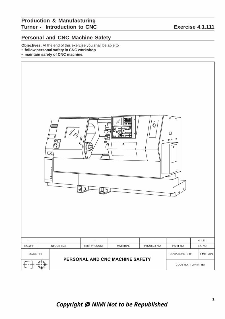
Personal and CNC Machine SafetyObjectives: At the end of this exercise you shall be able to• follow personal safety in CNC workshop• maintain safety of CNC machine.
Copyright @ NIMI Not to be Republished

2
Do’s• A well trained operator should operate the Machine.
• Only one operator should operate the machine at atime.
• Check the lubrication oil and Hydraulic oil level beforestarting the machine.
• Ensure doors are closed before switching ON theMachine.
• Keep less speed while operating in JOG mode, especiallywhen the tool is near the chuck/Job.
• Operator should ensure the machine zero point whilestarting the machine.
• Operator should check the work offset for every requiredset tool and the same to be entered in the program.
• Special care should be taken while changing the tool.
• Check the programme for correction before operating.
• Learn all G codes, and M codes, of the control installedin your machine .
• Learn all offset, Referrence points pertaining to yourmachine.
• Learn the basic maintenance schedule for yourmachine as per Autonomous maintenance.
• Ensure that the stabilizer is ON before starting.
Don’ts• Do not operate machine without the working knowledge
of the machine.
• Do not operate the machine when covers are removed.
• Do not insert any bar or tool holder in the spindle whilerotation.
• Do not open the control panel, without switching OFFpower.
• Do not operate the machine without trying in simulation.
• Do not attend electrical fault, without removing the mainfuse carriers
Production & Manufacturing : Turner (NSQF Level - 5) - Exercise 4.1.111Copyright @ NIMI Not to be Republished

3
Production & Manufacturing211.1.4 esicrexE CNC ot noitcudortnI - renruT
Identify the CNC machine and CNC consoleObjectives: At the end of this exercise you shall be able to• identify the CNC machine• identify the controllers of CNC machine axis.
2
Identify CNC controls
1
Copyright @ NIMI Not to be Republished

4
Instructor to guide the trainiees in majoridentification of CNC machine and in axiscontrol
Axis controller
Production & Manufacturing : Turner (NSQF Level - 5) - Exercise 4.1.112Copyright @ NIMI Not to be Republished

5
Sl No Name of the CNC Machine Console and the number of axis
1
2
3
TABLE: 2Job Sequence• Identify your CNC Machine and its console of axis
• List the name of CNC Machine in table - 1
• List the name and number of axis in table - 2
TABLE: 1
Sl. No Name of the CNC Machine with major M/C No identification ( Type & axis)
1
2
3
Production & Manufacturing : Turner (NSQF Level - 5) - Exercise 4.1.112Copyright @ NIMI Not to be Republished

6
Production & ManufacturingTurner- Introduction to CNC Exercise 4.1.113
Demonstration of CNC lathe Machine and its partsObjectives: At the end of this exercise you shall be able to• identify the parts of CNC lathe machine• list out the functions of each part of the CNC lathe Machine.
Copyright @ NIMI Not to be Republished

7
Job sequence• Identify the parts of CNC lathe Machine.
• List out the name of the parts shown in figure, inthe given table 1
• List out the function of each part in the given table 2.
Get it checked by the Instructor
• Instructor will demonstrate the parts.
TABLE 1
TABLE 2
Sl No. Name of the part Function of the part
1
2
3
4
5
6
7
8
9
10
11
12
13
1
2
3
4
5
6
7
8
9
10
11
12
13
Sl. No. Identify the parts of CNC turning centre
Production & Manufacturing : Turner (NSQF Level - 5) - Exercise 4.1.113Copyright @ NIMI Not to be Republished

8
Production & ManufacturingTurner- Introduction to CNC Exercise 4.1.114
Working of CNC Machine parts by using multimedia based simulatorObjectives: At the end of this exercise you shall be able to• operate the multimedia based simulator• identify the CNC Machine simulator.
Instructor will show the C.N.C Machine partsby using multimedia based simulator. Traineesshould identify parts and write in the formatgiven below.
Copyright @ NIMI Not to be Republished

9
Sl NO. CNC Parts Identified by trainee
1
2
3
4
5
6
7
8
9
10
11
Production & Manufacturing : Turner (NSQF Level - 5) - Exercise 4.1.114Copyright @ NIMI Not to be Republished
10
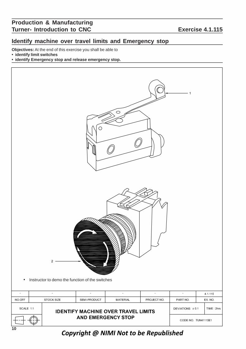
• Instructor to demo the function of the switches
Production & Manufacturing CNC ot noitcudortnI -renruT Exercise 4.1.115
Identify machine over travel limits and Emergency stopObjectives: At the end of this exercise you shall be able to• identify limit switches• identify Emergency stop and release emergency stop.
Copyright @ NIMI Not to be Republished

11
Job sequence• List the name of all the switches in CNC machine in
table 1
• List the name and purpose of the switches in table 2.
TABLE - 2
Sl.No Name of the switch Purpose of the switch
1
2 TABLE - 1
Sl. No Name of the switch
1
2
Production & Manufacturing : Turner (NSQF Level - 5) - Exercise 4.1.115
e.g. MDI Switch - helps in feeding manual Data
JOG mode switch - free movement of tool upwards /downwards
Copyright @ NIMI Not to be Republished

12
PROCEDURE
• Ensure the cleanliness of machine
• Use banian waste to clean
• Ensure there is no oil spill around the machine
• Switch ‘ON’ the Machine
Production & Manufacturing noitarepO ehtaL CNC -renruT Exercise 4.2.116
Conduct a preliminary check of readiness of the CNC turning centreObjectives: At the end of this exercise you shall be able to• check cleanliness of the machine• set the tool to machine reference point• check oil levels• check correct working of lubrication system.
• Move the tool in JOG mode to a safe place
• Set the tool to machine Reference point
• Check the lubrication oil level and ensure it is withinthe acceptable level.
• Check hydraulic oil level.
• Check coolant oil level
• Check correct working of lubrication system bymanual operation.
Copyright @ NIMI Not to be Republished
13
Production & Manufacturing noitarepO ehtaL CNC -renruT Exercise 4.2.117
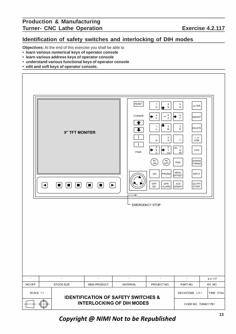
Identification of safety switches and interlocking of DIH modesObjectives: At the end of this exercise you shall be able to• learn various numerical keys of operator console• learn various address keys of operator console• understand various functional keys of operator console• edit and soft keys of operator console.
Copyright @ NIMI Not to be Republished

14
The instructor will demonstrate all the Safetyswitches and inter locking of DIH modes ofoperator console.
• List the safety switches in table 1
• List thefunction of keys in table 2
TABLE 1
Sl. No Name of the safety switches
1
2
3
4
5
TABLE 2
Sl. No Name of the safety switches/Functional key
ALTER
INSERT
DELETE
EOB
CAN
DGNOSPARAM
POS
Production & Manufacturing : Turner (NSQF Level - 5) - Exercise 4.1.115Copyright @ NIMI Not to be Republished

15
Production & Manufacturing noitarepO ehtaL CNC -renruT Exercise 4.2.118
Machine starting & operating in Reference point, JOG and Incremental modeObjectives: At the end of this exercise you shall be able to• switch ON CNC turning centre.• start the machine, and operate in JOG mode• start the machine and operate in Incremental mode.
• Instructor to Demo starting of the machine and its operating system.
Copyright @ NIMI Not to be Republished

16
Job sequence
Switch ON (main power supply)
↓Stabilizer ON
↓Machine main switch ON (Located at the side of the machine)
↓Release emergency button (By rotating clockwise direction)
↓N.C. ON (press the green button) To switch ‘ON’
↓ Display panel
Machine ‘ON’ (press the green button)
To switch ‘ON’
↓ Hydraulic & NC
Press control key or Menu key
↓Select “JOG” Mode
↓Give little movement by pressing (xt,zt,x-,x+)
C.N.C MACHINE STARTING AND OPERATING:
“ MACHINE ON” PROCEDURE (IN SINUMERIC)
Production & Manufacturing : Turner (NSQF Level - 5) - Exercise 4.1.118Copyright @ NIMI Not to be Republished

17
“MACHINE OFF” PROCEDURE
Press emergency button (Red colour)
Switch “OFF “ N.C (Red button)
Switch “ OFF” Machine (located at the side of the machine )
Switch “OFF” stabilizer
Switch “OFF” main power supply.
Note:Follow the above procedure to switch ‘OFF’ the machine. If the main is switched OFF without followingshutdown procedure, the MCU will get collapsed, just like in a computer system.
Production & Manufacturing : Turner (NSQF Level - 5) - Exercise 4.1.118Copyright @ NIMI Not to be Republished

18
REFERENCE POINT OR HOMING PROCEDURE
Press control key
Select referance point (By using soft keys and extension key)
Press xt (wait till it reaches to set value)
press z+ (wait till it reaches to set value)
Select “JOG” Mode
press z- (Tool moves near the Job)
Press x- (Tool moves near the Job)
Production & Manufacturing : Turner (NSQF Level - 5) - Exercise 4.2.118Copyright @ NIMI Not to be Republished

19Production & Manufacturing : Turner (NSQF Level - 5) - Exercise 4.2.118
Over store (In Sinumeric)
In over store mode we can operate the machine like conventional machine,by pressing X or Z axis keys withrespective sign. “This mode is mainly used for rotate the spindle”
Select “JOG” Mode
Diagnosis (Display C.R.T
(Press extension key)
Select over store=
Enter M03.S900 (use input key “yellow colour”)
Press execute key (green colour )
OR
Cycle “ON”
Copyright @ NIMI Not to be Republished

20
Production & ManufacturingTurner- CNC Lathe Operation Exercise 4.2.119Check CNC part programming simple exercises using various programmingcodesObjectives: At the end of this exercise you shall be able to• prepare the CNC part programe (Facing) with G00 and G01• start machine JOG and incremental modes.
PART PROGRAM: (IN SINUMERIC)
% 15
N5 G72 G90 G95
N10 G00 G53 X180 Z0;
N15 D05 M06 T03;
N 20 M03 S900 F0.1;
N 25 G00 X50 Z5;
N 30 G01 Z0-5;
N 35 X-1;
N 40 Z2 X 50;
N 45 Z-1;
N 50 X-1;
N 55 Z2 X50;
N 60 Z-1.5;
N 65 X-1;
N 70 Z2 X50;
N 75 D0 M05 M30;
Copyright @ NIMI Not to be Republished
21Production & Manufacturing : Turner (NSQF Level - 5) - Exercise 4.2.119
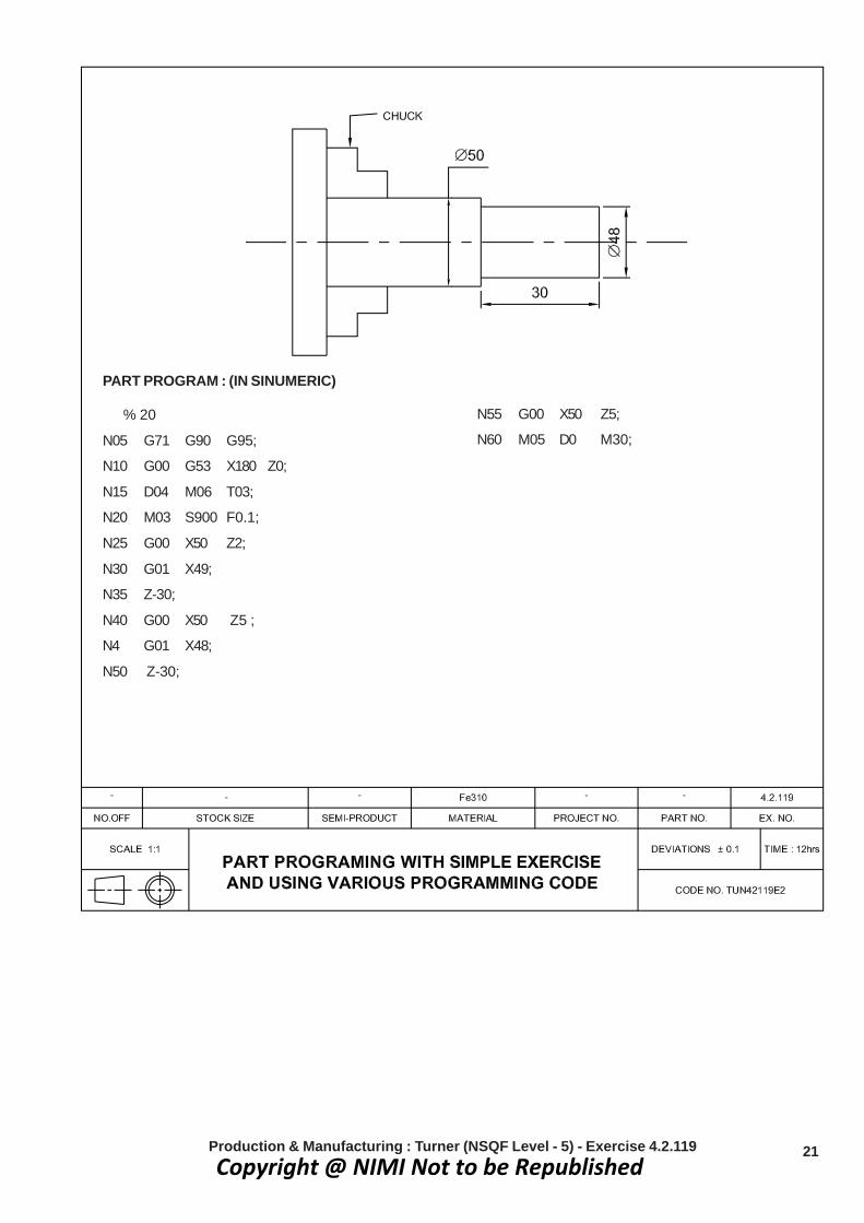
PART PROGRAM : (IN SINUMERIC)
% 20
N05 G71 G90 G95;
N10 G00 G53 X180 Z0;
N15 D04 M06 T03;
N20 M03 S900 F0.1;
N25 G00 X50 Z2;
N30 G01 X49;
N35 Z-30;
N40 G00 X50 Z5 ;
N4 G01 X48;
N50 Z-30;
N55 G00 X50 Z5;
N60 M05 D0 M30;
Copyright @ NIMI Not to be Republished

22 Production & Manufacturing : Turner (NSQF Level - 5) - Exercise 4.2.119
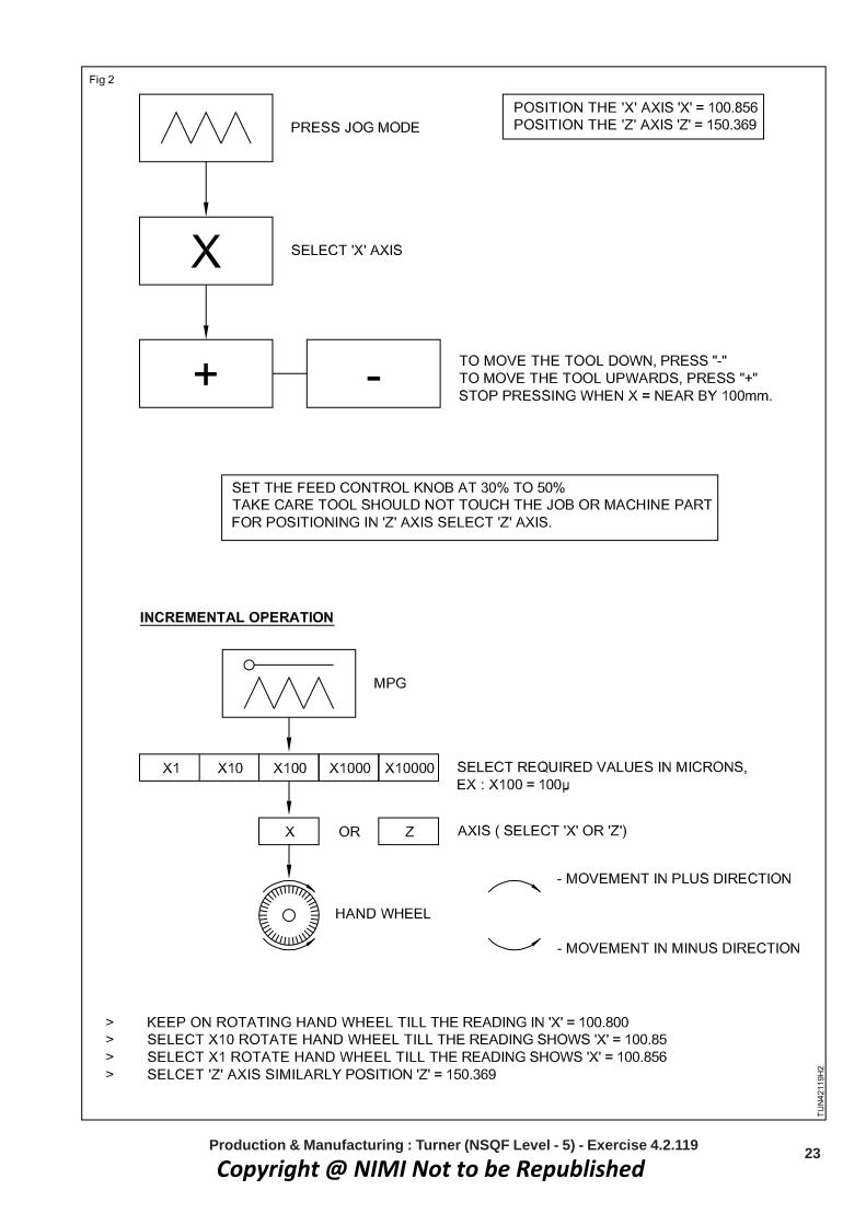
Skill sequenceAxis Movement
Job sequence• Study the drawing dimension
• Check the raw material for the required size
• List out the G code & M Code needed for theprogramme
• Prepare & write down the part programe
• Ensure the tool T03 in place
• Hold the job on machine chuck & clamp securely
• Get the program checked for its correctness (AvailInstructor’s help)
• Try to make few similar program for some othercomponents made earlier
TASK 1 : Procedure for JOG feed
• Press the JOG mode switch
• Select the axis to be moved.
• Keep the feed rate switch open.
• Keep pressing the Direction switch untill the toolreaches the desired position.
TASK 2 : Procedure for incremental feed• Select he INC mode.
• Keep the feed rate switch open
• Select the distance to be moved in each stepwith the magnification dial.
• Select the axis.
• Press the distance switch.
• Note the movement of the axis.
TASK 3 : Procedure for manual handle feed (MPG MODE)
• Press the HANDLE switch
• Select the axis.
• Select the incremental value.
• Move the tool along selected axis by rotating the handle360° Move the tool the distance equivalent to 100graduation.
The instructor will demonstrate the various axisand modes.
Copyright @ NIMI Not to be Republished
23Production & Manufacturing : Turner (NSQF Level - 5) - Exercise 4.2.119
Copyright @ NIMI Not to be Republished

24
Production & Manufacturing noitarepO ehtaL CNC -renruT Exercise 4.2.120
Check the programme simulation on machine(or)practice in simulationsoft ware in respective control systemObjectives: At the end of this exercise you shall be able to• write the programme in edit mode• practice the simulation on machine (or) simulation soft ware contol system.
Copyright @ NIMI Not to be Republished

25
Job Sequence• Switch ON N.C (or) switch on multmedia based control
system.
• Select the edit mode
• Write the programme
• Select the simulation mode
• Observe the tool path and programme sequence.
• In case tool path is wrong correct the programme inedit mode.
• See the simulation again
• If the programme is correct
• Exit the simulation mode
• switch off the N.C control (or) simulation control system.
• Instructor to guide the trainee to write various programmeand see the simulation on the machine (or) in thesoftware control system
Skill sequenceComputer simulationA computer simulation is an attempt to model a real- lifeor hypothetical situation on a computer so that it can bestudied to see how the system works. By changingvariables in the simulation, predictions may be made aboutthe behaviour of the system. It is a tool to virtuallyinvestigate the behaviour of the system under study.
Computer simulation has become a useful part of modelingmany natural systems in physics,chemistry and biology.and human systems in economics and social science(e.g., computational sociology) as well as in engineeringto gain insight into the operation of those systems. Agood example of the usefulness of using computers tosimulate can be found in the field of network trafficsimulation. In such simulations, the model behaviour willchange each simulation according to the set of initialparameters assumed for the environment.
Production & Manufacturing : Turner (NSQF Level - 5) - Exercise 4.2.120
Traditionally,the formal modeling of systems has beenvia a mathematical, which attempts to find analyticalsolutions enabling the prediction of the behaviour of thesystem from a set of parameters and initial conditions.Computer simulation is often used as an adjunct to,orsubstitution for, modeling systems for which simple closedform of analytic solutions are not possible. There are manytypes of computer simulation,the common feature theyall share is, the attempt to generate a sample ofrepresentative scenarios for a model in which a completeenumeration of all possible states would be prohibitive orimpossible.
Several software packages exist for running computerbased simulation modeling (eg.,Monte Carlosimulation,stochastic modeling, multi method modeling)that makes all the modeling almost effortless.
Modern usage of the term “computer simulation” mayencompass virtually any computer -based representation.
Copyright @ NIMI Not to be Republished

26
Production & Manufacturing noitarepO ehtaL CNC -renruT Exercise 4.2.121
Absolute & Incremental programming Assingments by simulationObjectives: At the end of this exercise you shall be able to• learn absolute and incremental dimension of job.
Method of DimensioningThere are two methods of dimensioning .
1 Absolute system of dimensioning (or) fixed zerosystem of dimensioning.
2 Incremental system of dimensioning (or) floating zerosystem of dimensioning. (or) previous point zerosystem of dimensioning.
Absolute dimensions programmingIn absolute dimensions programming all the point ofthe tools is coming from the datum point (or) zero point.
Incremental dimensions programmingIn this system, tool move form the previous point.
Example 1 : The points 1 to 5 in the drawing indicatesthe absolute in Table 1 and Incremental in Table 2
TABLE 2
Incremental
Position U W
1 0.0 0.0
2 25.0 0.0
3 00.0 - 70.0
4 10.0 - 00.0
5 00.0 - 30.0
Absolute program in table 1.
Incremental program in table 2.
TABLE1
Absolute
Position X Z
1 0.0 0.0
2 50.0 0.0
3 50.0 - 70.0
4 70.0 - 70.0
5 70.0 -100.0
Copyright @ NIMI Not to be Republished

27
Exercise for Absolute & Incremental Methods
Write the points for the following figures in absolute &incremental dimension programming.
Exercise1 : (Fig 1)
Exercise 2 : (Fig 2)
Trainees to indicate the co-ordinate values in the giventables.
ABSOLUTE
Position X Z
1
2
3
4
5
6
INCREMENTAL
Position U W
1
2
3
4
5
6
7
INCREMENTAL
Position U W
1
2
3
4
5
6
ABSOLUTE
Position X Z
1
2
3
4
5
6
7
Production & Manufacturing : Turner (NSQF Level - 5) - Exercise 4.2.121
Copyright @ NIMI Not to be Republished

28
Production & Manufacturing noitarepO ehtaL CNC -renruT Exercise 4.2.122
Linear Interpolation and Circular Interpolation assignments and simulationon softwareObjectives: At the end of this exercise you shall be able to• prepare the various programme in linear, circular interpolation• check the simulation on software in multimedia system.
BASIC MOVEMENT BLOCKS
TASK 1
Rapid positioning G00 X...Z
TASK 2
Linear Interpolation G0 1 X... Z..
TASK 3
Circular Interpolation (CW) G02 G90 X.. Z..
TASK 4
Circular Interpolation (CCW) G03 G90 X..Z..
Copyright @ NIMI Not to be Republished

29
RAPID POSITIONING
LINEAR INTER POLATION
WRITE AND SIMULATE THE PROGRAM
TASK 1
WRITE AND SIMULATE THE PROGRAM
TASK 2
CIRCULAR INTER POLATION
WRITE AND SIMULATE THE PROGRAM
TASK 3
CIRCULR INTER POLATION (CCW)
WRITE AND SIMULATE THE PROGRAM
TASK 4
Production & Manufacturing : Turner (NSQF Level - 5) - Exercise 4.2.122Copyright @ NIMI Not to be Republished

30
PROCEDURE :• Ensure the work secured firmly in chuck
• Now bring the tool in JOG mode near the face ofjob
• Switch ‘ON’ spindle
• Carry out light facing of the job
• After the finish cut,move the tool back in X-directiononly
• Now switch off spindle
• Go to Tool off set mode
• Press GEOM soft key and position the cursor usingcursor movement button and select the offsetnumber
• Enter the Z-axis value Z0.0
• Press softkey.
• Now rotate the spindle in appropriate directionand machine the outside diameter (‘OD’)
• Do not distrub X-axis
Production & ManufacturingTurner - Tool Setting and Data Input Exercise 4.3.123Peform work and tool setting & tool setup and live tool setupObjectives : At the end of this exercise you shall be able to• set the job in CNC machine chuck / tool holder• set the tool in the respective slot of the turret.
• Take tool away in Z- direction only
• Stop the spindle
• Measure the outer diameter of the job usingmicrometer
• Go to OFFSET softkey
• Press GEOM softkey
• Position the cursor to the required tool offsetnumber and enter the measured value. [eg : X32.62]
• Press softkey
• Repeat the procedure for all the tools
• After taking offset select MDI and
• Ensure the work zero
Copyright @ NIMI Not to be Republished
31
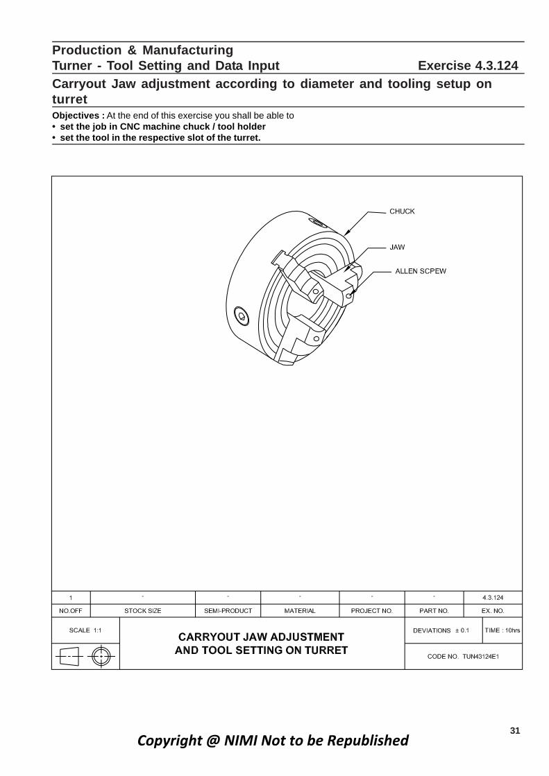
Production & ManufacturingTurner - Tool Setting and Data Input Exercise 4.3.124Carryout Jaw adjustment according to diameter and tooling setup onturretObjectives : At the end of this exercise you shall be able to• set the job in CNC machine chuck / tool holder• set the tool in the respective slot of the turret.
Copyright @ NIMI Not to be Republished

32
Tool Setting on Turret• Select the tool number on turret by JOG or MDI mode.
• Loosen a pair of allen Screw near the tool slot on turret
• Insert shank of tool
• Tighten the allen screws
• Take tool OFF Set for that tool before using.
• Add tool OFF Set number in the respective program.
Production & Manufacturing : Turner (NSQF Level - 5) - Exercise 4.3.124
PROCEDURE
• Loosen allen Screw of all the three jaws.
• Count the number of Serration radially outwards
• Leave equal number of serration (Racks) outwards andhold jaws firmly.
• Ensure the space slightly higher than the diameter ofjob.
• Tighten the allen Screws.
• Check concentricity of job using dial test indicator.
Copyright @ NIMI Not to be Republished
33
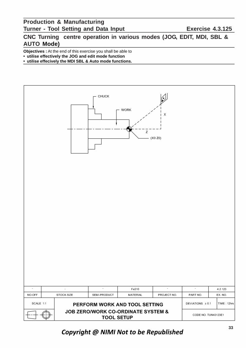
Production & ManufacturingTurner - Tool Setting and 521.3.4 esicrexE tupnI ataDCNC Turning centre operation in various modes (JOG, EDIT, MDI, SBL &AUTO Mode)Objectives : At the end of this exercise you shall be able to• utilise effectively the JOG and edit mode function• utilise effecively the MDI SBL & Auto mode functions.
Copyright @ NIMI Not to be Republished

34
JOG Mode• Set in Jog mode, use mode selector switch
• Press X- (or) X+axis button
• To move in X - (or) X + as per required direction
• In the same manner we can move in Z direction also.
• Keep pressing the direction switch till the tool reachesthe desired position.
Edit Mode• Set edit mode using mode selector switch
• Enter the New programme in block by block
• To use input /alter/delete/ EOB keys.
• To alter the program, if any correction of the programmeis needed, go to edit mode.
MDI modeManual data input key and functions.
• When the machine is not running a part program theoperator may use this mode.
• Only one block is executed at a time.
• Once it is executed, it is gone from the computer inmemory.
• An operator can use MDI mode to change cutting tool,spindle ON /OFF, Coolant ON/OFF, etc.,
Single block modeSingle block mode allows an operator to check theprogram by executing only one program block at a time.
Example
N1 G01 X50 Z5 F0.1 ;
N2 S1200 M03 ;
N4 M08 ;
N5 G01 X48 F0.1 ;
N6 G01 Z-25 F0.1 ;
N7 G00 X60 Z10 ;
N8 M09 ;
N9 M05 ;
N10 M30 ;
Auto Mode• To select the programme numbers before selecting the
Auto mode.
• To set Auto mode using mode selector switch.
• Press the cycle start button.
• With this mode, programme will be executed continouslyin block- by - block.
• While machine is running in this mode do not change toany other mode or function.
Note : before machine running continously inAuto mode, first job will be executed in singleblock.
Note : The instructor will demo the variousmodes.
Production & Manufacturing : Turner (NSQF Level - 5) - Exercise 4.3.124Copyright @ NIMI Not to be Republished

35
Go to JOG Mode
Press Part Program
Press edit
Enter % and new program number of Job
Press Select Program
(Blank space open for entry of program)
Write program using numerical key and edit key
Production & ManufacturingTurner- Tool setting Data Input Exercise 4.3.126
Program Entry In C.N.C latheObjectives: At the end of this exercise you shall be able to• enter the programme in FANUC control.
Program Executive In Sinumeric Contorl
Go to Automatic Mode
Enter Program Number
Press execute key or cycle ON key
Job Sequence
Fanuc Control%
0.0001
NI;
G28 V0 W0;
G97 S1000 M03;
T0101;
G00 X45.0 Z5.0 M08;
Z0.0;
G01 X0.0 F0.1;
G01 X20.0 F0.1;
G01 Z- 25.0 F0.1;
G01 X30.0 F0.1;
G01 Z-50.0 F0.1;
G01 X40.0 F0.1
G01 Z -75.0 F0.1;
G00 X 50.0 Z10.0 M09;
G28 U0 W0
M05;
M01;
M30;
A lower speed range is suitable for heavyrange cuts.A higher speed range is suitable forlight finishing cuts. The feed rate to be decidedbased on the type of finish required.
Instructor to guide the Trainee in Edit programbecause more depth of cut is involved.
Copyright @ NIMI Not to be Republished
36
Production & Manufacturing721. 3.4 esicrexE tupnI ataD dna gnitteS looT- renruT
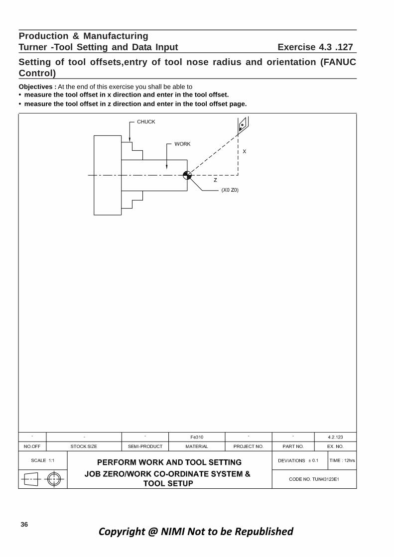
Setting of tool offsets,entry of tool nose radius and orientation (FANUCControl)Objectives : At the end of this exercise you shall be able to• measure the tool offset in x direction and enter in the tool offset.• measure the tool offset in z direction and enter in the tool offset page.
Copyright @ NIMI Not to be Republished

37
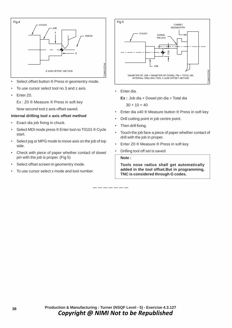
Job sequenceFANUC controlTool offset method
X axis tool offset methodReference tool is T01 and offset is zero in X and Zaxis• Clamping job in chuck.
• Select MDI mode. Press in MDI prog-screen.
• Enter tool number : T0202(Turning tool).
Insert button ® Press ® Cycle start button ® Press
• Tool cutting edge position with spindle ON CW or CCWin MDI mode.
Enter MO3 SI500 ® Reset button press ®Cycle start button.
• To select jog mode or MPG mode to move x and zaxis.
• Touch the job in x axis just clean OD turning to ensureno disturbance in x axis. (Fig 1)
• Then stop spindle button.
• To measure job OD diameter, use vernier (or)micrometer for sample Æ28.62 mm.
• Select Offset button ® Press ® displayed in geometrymode.
• Using cursor in geomentry screen select Tool no : 1 xaxis select.
• Enter job diameter
Ex: x28.62 ® Measure button ® Press in soft key
• Now tool cutting edge in job centre is OK.
• Tool offset in X axis is saved
Z axis offset method• Spindle ON rotate the job.
• Select jog mode or MPG mode to move axis. Manuallyturning job facing position no disturbance Z axis.(Fig 2)
• Select offset button press in geomentry mode.
• Select offset button press in geomentry mode.
• Use cursor select tool no 3 and x axis.
• Enter constant same dia.
Ex: x28.62 ® Measure button ® Press in soft key
Threading tool offset measurementZ axis offset• Select MPG mode in incremental variation. To move
axis z position.
• To check by inserting a piece of paper between tooland the job ensuring that there is no disturbance in Zaxis (Fig 4).
Production & Manufacturing : Turner (NSQF Level - 5) - Exercise 4.3.127
• To use cursor select tool no 1 and z axis.
• Enter Z0.
Enter Z0 ® Measure ® Press in soft key
• Now z axis tool offset OK.
• Tool offset is Z axis is saved
Second tool offset• Select MDI mode ® Press ® MDI Prog ® Screen.
• Enter tool no (Threading tool) T0303 ® Reset button ®Press ® Cycle start.
• Select jog mode or MPG mode then move axis.
• Same procedure MPG mode incremental touch job xaxis with piece of paper whether contact of tool in jobconstant dia proper. No disturbance axis. (Fig 3)
Copyright @ NIMI Not to be Republished
38
• Select offset button ® Press in geomentry mode.
• To use cursor select tool no 3 and z axis.
• Enter Z0.
Ex : Z0 ® Measure ® Press in soft key
Now second tool z axis offset saved.
Internal drilling tool x axis offset method• Exact dia job fixing in chuck.
• Select MDI mode press ® Enter tool no T0101 ® Cyclestart.
• Select jog or MPG mode to move axis on the job of topside.
• Check with piece of paper whether contact of dowelpin with the job is proper. (Fig 5)
• Select offset screen in geomentry mode.
• To use cursor select x mode and tool number.
• Enter dia.
Ex : Job dia + Dowel pin dia = Total dia
30 + 10 = 40
• Enter dia x40 ® Measure button ® Press in soft key
• Drill cutting point in job centre point.
• Then drill fixing.
• Touch the job face a piece of paper whether contact ofdrill with the job in proper.
• Enter Z0 ® Measure ® Press in soft key
• Drilling tool off set is saved
Note :Tools nose radius shall get automaticallyadded in the tool offset.But in programming,TNC is considered through G codes.
Production & Manufacturing : Turner (NSQF Level - 5) - Exercise 4.3.127Copyright @ NIMI Not to be Republished

39
Production & ManufacturingTurner - Tool Setting and Data Input Exercise 4.3.128Conduct work offset measurement, tool offset measurement and entry inCNC controlObjectives : At the end of this exercise you shall be able to• measure work offset in z axis• measure work offset in x axis• enter the offset values in work offset area.
Copyright @ NIMI Not to be Republished

40
2JobofdiameterActualofvalueThe
L1−×
=
1.47L12
2.94L1
231.6228.68
L1
−∴
−=
−=
2JobofdiameterActualXofvalueThe
L1−
=
Skill SequenceTool off set (In sinumeric)
Tool off set is done to find out work zero.
To do the tool offset we have to find the tool geometry (i.eL1 and L2) for each tool.
L2 Geometry :Run the spindle take the tool towards theface of the job and face it, if length permits note down thevalue of Z ie. the value of L2.
Example L2 = -294.754 (Directly taken from thesystem)L1 Geometry :In JOG mode run the spindle, take the tool towardsdiameter of the job and touch it and do plain turning (if
Job sequenceWork offset measurement in z axis• Clamping job in chuck.
• Select MDI mode (Make any tool generating firstoperation tool).
• Index the tool position with tool offset cancel.
• Enter tool number : TO100.
Insert button ® Press ® Cycle start button ® Press
• Tool cutting edge position with spindle ON CW or CCWin MDI mode.
Enter MO3 SI500 ® Insert button press ®Cycle start button ® Press
• To select jog mode or MPG mode to move x and zaxis.
• Touch the job in face position and just facing nodisturbance in z axis.
• Select work offset screen to use cursor to choose G54work coordinate.
• Enter Z0.
Ex: Z0 ® Measure button ® Press in soft key
Work offset measurement in x direction• Clamping job in chuck.
• Select MDI mode ((Make any tool generally firstoperation tool).
• Index the tool position with tool offset cancel.
• Enter tool number : T0100.
Resert button ® Press ® Cycle start button ® Press
• Tool cutting edge position with spindle ON CW or CCWin MDI mode.
Enter MO3 SI500 ® Insert button ® press ®Cycle start button ® Press
• To select jog mode or MPG mode to move x and zaxis.
• Tool touch the job in x axis just clean OD turning. Nodisturbance measure dia by use vernier or micrometer.
• Select work offset screen to use cursor to choose G54work coordinate.
• Enter job dia.
Ex:
x32.65 Measure button ® Press in soft key
material allows) and note down the value of x and measurethe diameter of the work then find out L1 by using thefollowing formula.
Production & Manufacturing : Turner (NSQF Level - 5) - Exercise 4.3.128
Example : The value of x = 28.68 (from control panel )
Actual dia of work = 31.62 mm
Copyright @ NIMI Not to be Republished
41
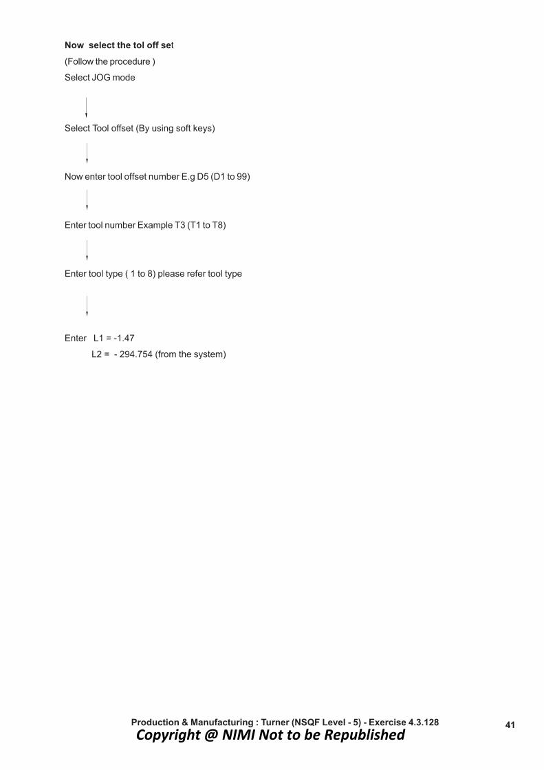
Now select the tol off set
(Follow the procedure )
Select JOG mode
Select Tool offset (By using soft keys)
Now enter tool offset number E.g D5 (D1 to 99)
Enter tool number Example T3 (T1 to T8)
Enter tool type ( 1 to 8) please refer tool type
Enter L1 = -1.47
L2 = - 294.754 (from the system)
Production & Manufacturing : Turner (NSQF Level - 5) - Exercise 4.3.128Copyright @ NIMI Not to be Republished

42
Production and ManufacturingTurner - Tool Setting and data input Exercise No. 4.3.129Make Tool nose radius and tool orientation entry in CNC controlObjective: At the end of this exercise you shall be able to• set the tool nose radius compensation• set the tool imaginary nose position to ‘T’ in tool geomentry offset.
Copyright @ NIMI Not to be Republished

43
Job Sequence• To study the drawing
• To select the suitable tool for the operation
• Identify the tool type
Production & Manufacturing : Turner (NSQF Level - 5) - Exercise 4.3.129
Skill SequenceThe following data’s must be specified to carryoutautomatic tool nose radius compensation to obtainrequired profile exactly
• For external turning and to move the tool in left withrespect to job program as G41 ( Tool left) and to movetool right with respect to job program as G42 (Toolright)
• For internal turning like boring and to move left withrespect to the job the tool program as G41 (Tool Left )and to move the tool right with respect to job, programas G42 (Tool right)
• To study the tool nose radius
• To input the value of tool nose radius in G41 & G42 inthe programme.
• Input the radius of tool to R in geometry offset.
• Input the imaginal nose position in ‘T’ in geometryoffset.
Imaginary nose position to Tool offset in Geometry offset (Tool type)Method - I Method - II
Copyright @ NIMI Not to be Republished

44 Production & Manufacturing : Turner (NSQF Level - 5) - Exercise 4.3.129
Method - III
Copyright @ NIMI Not to be Republished

45
Production & ManufacturingTurner - Tools Setting and Data input Exercise 4.3.130
Jaw removal and mounting on CNC latheObjectives : At the end of this exercise you shall be able to• remove the jaw and reload it• chock the concentricity with dial test indicator.
Job Sequence• Loosen allen screws of all the three jaws
• Count the number of serration radially outwards
• Leave equal number of serration (rack) outwardsand hold jaws firmly
• Ensure the space slightly higher than thediameter of job
• Tighten the allen screw using suitable allen key.
Copyright @ NIMI Not to be Republished

46
Job Sequence (Write the programme and execute)
Production & ManufacturingTurner-Tool Setting and Data input Exercise 4.3.131Manual Data Input (MDI) ,MPG Mode Operations & checking Zero Offsetand Tool OffsetsObjective: At the end of this exercise you shall be able to• data input and operation of MDI & MPG mode.
• N5 G00 D5 T3 M03 S600 X 35 Z10.
• N10 x 35.Z5;
• MDI Mode helps to cross check the tool off set (workzero)
• In M.D.I mode one Instruction (Block) can be executed
• It allows the operator to enter and execute the blocksprogramming code manually on the control panel.
Note :
Go to M.D.I mode only on completion of tooloffset. Feed rate should be with in 10 to 15%)
Copyright @ NIMI Not to be Republished

47
Production & ManufacturingTurner - Programming and Simulation Exercise 4.4.132
Program checking in dry run single block modeObjectives : At the end of this exercise you shall be able to• check the program in Dry run• check the program in single block mode.
Copyright @ NIMI Not to be Republished

48
• It is also used to execute the first job.
The instructor demo the ‘Dry Run’ to thestudents
Press Simulation
Reset
START
Program check in dry run, single block mode (Insinumetric)Dry run is to be carried out to check :• To perform trial option of the part programming
• The path or profile of the job and
• The error in the programme
• To avoid any Accidental incident
• The effectiveness of the program.
• It is used to check the program for correctness.
Production & Manufacturing : Turner (NSQF Level - 5) - Exercise 4.4.132
Note : After entry of the program it should bechecked through simulation
• Single block mode is used to allow the operator, toexecute the part program at a time on the single block.
Copyright @ NIMI Not to be Republished

49
Production and ManufacturingTurner - Programming and Simulation Exercise 4.4.133
Checking Finish size by over sizing through tool offsetObjective: At the end of this exercise you shall be able to• do the correction of size in tool offset.
Copyright @ NIMI Not to be Republished

50
PROCEDURE• Switch ON machine as per procedure
• Enter the program as per drawing
• Run the simulation on dry run with machine
• If there is no error run the machine in SBL or Auto mode
• Check the finished dimensions
• If there is any error compared to the required dimensioncalculate the difference
• Add the difference in value to the respective axis in thetool offset
• Run and produce a sample to the correct measurement.
Tool Number X axis Value Z axis Value
1 - 0 .02 0.05
2
3
4
• Go to wear offset page and input the X,Z differencevalue
After complete the operation enter actual value of job
Tool Numbers X axis Value Z axis Value
1 20.02 45.05
2
3
4
Note :• Required size of the is job X 20 ± 0.00
Z 45 ± 0.00
• Add the Tool wear offset difference value on the tablecolumn
• To avoid the rejection of job the first piece is made,slightly increased in size in offset.
• After completion of the first piece,check all thedimension without removing the chuck.
• Observe the difference value of drawing size and Acutalsize, and this difference, if any, should be ‘input’ in thewear off set.
Production & Manufacturing : Turner (NSQF Level - 5) - Exercise 4.4.133Copyright @ NIMI Not to be Republished

51
Job sequence • Switch on the CPU and monitor.
• Select the software.
• Study the drawing.
• Enter the programming in edit mode./key board.
• Select required tool and clamping device.
• Run the simulation in auto mode.
• Tranfer the programe to the machine.
• Take the offset.
• Run the machine in Automatic mode.
• Check the dimension and remove the job.
• Switch of the machine.
Production & ManufacturingTurner - Programming and Simulation Exercise 4.4.134
Part program preparation simulation and automatic mode executionObjectives: At the end of this exercise you shall be able to• write the part program for turning, facing and step turning• input the program in to the computer / simulator• operate the simulator• transfer the machine to simulated programe.
Copyright @ NIMI Not to be Republished

52
Part Program For FANUC
0000;
NI;
G28 U0 W0;
G50 S 1500 T0 101
G96 S150 M03;
G00 X50.0 Z5.5 M08;
Z0.0;
G01 X-1.0 F0.1;
G00 X42.5 Z2.0;
G01 Z-55.0 F0.1;
G00 X50.0 Z2.0;
X40.3;
G01 Z-55.0 F0.1;
G00 X50.0 Z2.0;
X37.5;
G01 Z-35.0 F0.1;
G00 X50.0 Z2.0;
X35.3;
G01 Z-35.0 F0.1;
G00 X50.0 Z2.0;
X32.5;
G01 Z - 15.0 F0.1;
G00 X 50.0 Z2.0;
X30.3;
G01 Z-15.0 F0.1;
G00 X50.0 Z2.0;
X0.0;
G01 Z0.0 F0.1;
X30.0;
Z-15.0;
X35.0;
Z-35.0;
X40.0;
Z-55.0;
G00 X55.0; Z 5.0 M09
G28 U0 W0;
M05;
M30;
Part Program for Sinumeric
%1.
N1 G71 G90 G95;
N2 G00 G53 X180 Z0;
N4 S1500 M03;
N5 T1 D1 M06;
N6 G00 X50 Z5 M08
N7 G00 Z0;
N8 G01 X-1 F0.1;
N9 G00 X42.5 Z2;
N10 G01 Z- 55.0 F0.1;
N11 G00 X50 Z2;
N12 G00 X 40.3
N13 G01 Z-55 F0.1;
N14 G00 X50.0 Z2;
N15 G00 X37.5;
N16 G00 Z-35 F0.1;
N17 G00 X50 Z2;
N18 G00 X35.3;
N19 G01 Z-35 F0.1;
N20 G00 X50 Z2;
N21 G00 X32.5;
N22 G01 Z-15 F 0.1;
N23 G00 X50. 0 Z2;
N24 G00 X30.3;
N25 G01 Z-15.0 F0.1;
N26 G00 X50 . 0 Z2;
N27 G00 X0;
N28 G01 Z0 F0.1;
N29 G01 X30 F0.1;
N30 G01 Z-15 F0.1;
N31 G01 X35 F0.1;
N32 G01 Z-35 F0.1;
N33 G01 X40 F0.1;
N34 G01 Z-55 F0.1;
N35 G00 X55 Z5 M09;
N36 D0;
N37 G00 G90 G53 X180 Z0;
N38 M05;
N39 M30;
Production & Manufacturing : Turner (NSQF Level - 5) - Exercise 4.4.134Copyright @ NIMI Not to be Republished
53
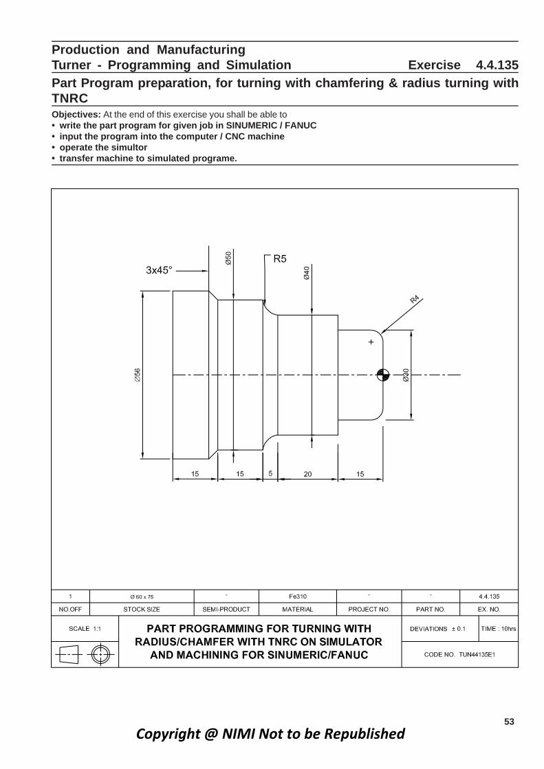
Production and ManufacturingTurner - Programming and Simulation Exercise 4.4.135Part Program preparation, for turning with chamfering & radius turning withTNRCObjectives: At the end of this exercise you shall be able to• write the part program for given job in SINUMERIC / FANUC• input the program into the computer / CNC machine• operate the simultor• transfer machine to simulated programe.
Copyright @ NIMI Not to be Republished

54
R - PARAMETER FOR STOCK REMOVAL CYCLE(L95)
R 20 = Sub Program Number or Sub routine No.
R 21 = Starting position of X axis (Absolute)
R22 = Starting position of in Z axis (Absolute)
R23 = Finishing allowance of X (Incremental)
R24 = Finishing allowance of Z (Incremental)
R26 = Roughing cuts
R27 = Tool Nose Radius compensation
R29 = Type of turning (Roughing , Finishing)
L95 = Stock removal cycle
P1 = No.of Tool passes
Job Sequence
• Switch ON the CPU and Monitor.
• Select the software.
• Enter the program in edit mode.
• Select required tool and clamping device.
• Select the path.
• Run the Simulation in AUTO mode .
• Transfer the programe to the machine.
• Take the offset.
• Check the dimension and remove the job.
• Switch off the machine.
PART PROGRAM (IN SINUMERIC)
% 225
N5 G71 G90 G95;
N10 G00 G53 X180 Z0;
N15 D5 T5
N20 M03 S900 F0.1;
N25 G00 X65 Z2;
N30 R20 =185 R21=65 R22=0 R23=0.3 R24=0.3R26 =1 R27=42 R29=41 L95 P1; (stockRemoval cycle)
N35 D0 M05;
N40 G00 G90 G53 X180 Z0;
N45 M30;
L185 (SUB PROGRAM)
N5 G01 X0 F0.1;
N10 G01 Z0 F0.1;
N15 G01 G42 X22 F0.1;
N20 G90 G03 X30 Z-4 B4 F0.1;
N25 G01 Z-15 F01.;
N30 X40;
N35 Z-35;
N40 G90 G02 X50 Z-40 B5;
N45 G01 Z-55;
N50 X56 Z-58;
N55 G01 G40 Z-70;
N60 X65;
N65 M17;
Production & Manufacturing : Turner (NSQF Level - 5) - Exercise 4.4.135
Copyright @ NIMI Not to be Republished

55
PART PROGRAM [ FANUC]
O0002
N1;
G28 U0 W0
G97 S1500 M03;
T0101;
G00 X65.0 Z5.0 M08;
G01 Z2.0 F.01;
G71 U1.0 R1.0;
G71 P10 Q20 U0.3 W0.1 F0.1;
N10 G01 X0.0 F0.1;
G01 Z0.0 F0.1;
G01 G42 x 22.0 F0.1;
G03 X30.0 Z-40 R4 F0.1;
G01 Z-15.0 F0.1;
X40.0;
Z-35.0;
G02 X50.0 Z - 40 R5 F0.1;
G01 Z-55.0 F0.1;
X56.0 Z-58.0;
N20 G01 G40 Z-70.0 F0.1;
G00 X65.0 Z5.0 M09;
G28 U0 W0;
M05;
M30;
G71 - Turning Cycle
G71 U --- R --- ;
G71 P --- Q --- U --- W --- F --- ;
U : Depth cut per pas in ‘X’ axis (Radial Value)
R : Relief Amount
P : Starting block number
Q : Ending block number
U : Finishing Allowance in ‘X’ axis
W : Finishing Allownace in ‘Z’ axis
F : Feed
Production & Manufacturing : Turner (NSQF Level - 5) - Exercise 4.4.135
Copyright @ NIMI Not to be Republished

56
Production & ManufacturingTurner - Programming and Simulation Exercise 4.4.136
Part programme preparation with contours with TNRC and simulationObjectives : At the end of this exercise you shall be able to• write the part program for the given job in fanuc control and simulate the programme• input the program into the CNC machine• execute the program in auto mode.
Copyright @ NIMI Not to be Republished
57
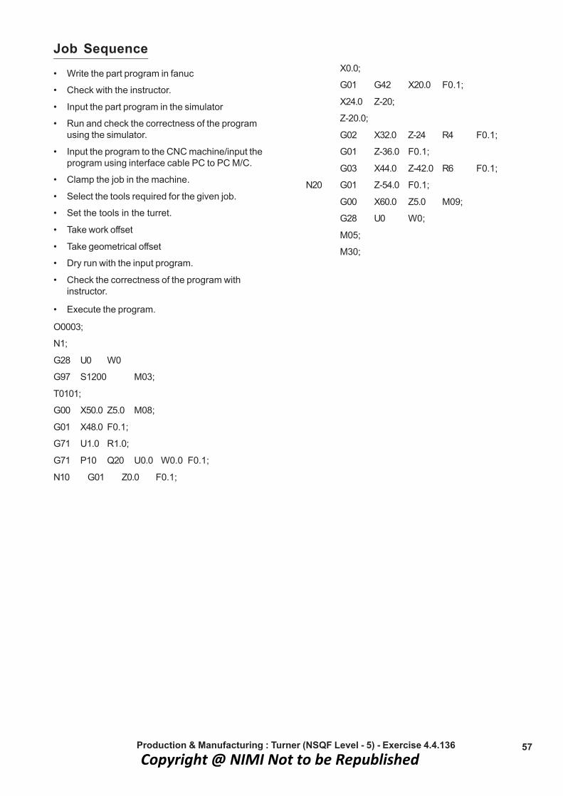
Job Sequence• Write the part program in fanuc
• Check with the instructor.
• Input the part program in the simulator
• Run and check the correctness of the programusing the simulator.
• Input the program to the CNC machine/input theprogram using interface cable PC to PC M/C.
• Clamp the job in the machine.
• Select the tools required for the given job.
• Set the tools in the turret.
• Take work offset
• Take geometrical offset
• Dry run with the input program.
• Check the correctness of the program withinstructor.
• Execute the program.
O0003;
N1;
G28 U0 W0
G97 S1200 M03;
T0101;
G00 X50.0 Z5.0 M08;
G01 X48.0 F0.1;
G71 U1.0 R1.0;
G71 P10 Q20 U0.0 W0.0 F0.1;
N10 G01 Z0.0 F0.1;
X0.0;
G01 G42 X20.0 F0.1;
X24.0 Z-20;
Z-20.0;
G02 X32.0 Z-24 R4 F0.1;
G01 Z-36.0 F0.1;
G03 X44.0 Z-42.0 R6 F0.1;
N20 G01 Z-54.0 F0.1;
G00 X60.0 Z5.0 M09;
G28 U0 W0;
M05;
M30;
Production & Manufacturing : Turner (NSQF Level - 5) - Exercise 4.4.136Copyright @ NIMI Not to be Republished

58
Production & ManufacturingTurner - Programming and Simulation Exercise 4.4.137
Machining parts on CNC Lathe with Parallel, Taper, Step, Radius Turning,Grooving and ThreadingObjectives : At the end of this exercise you shall be able to• input the program into machine• set the machine with necessary tools• take the tool offset.• run the machine to produce the job.
Copyright @ NIMI Not to be Republished

59
Job Sequence
• Study the part drawing and list the tools required
• Prepare the CNC programme
• Get it checked by the instructor.
• Check the raw material size and confirm with the partdrawing, for its correctness
• Hold the job on chuck by projecting 55mm length inturning
• Enter the above part programme in your CNC machine
• Set the tool to the required turret station .
• Measure the work offset in X and Z direction and enterin the relevant work offset page G54/G5.
• Measureall the tool offset in X ‘and Z and enter thegeometry offset page.
• Enter the tool type and tool nose radius
• Check the work offset and tool offset
If there is any mistake, correct the programmeand ask your instructor for guidance
• Run the programme in single block by shifting the offsetaway from the work area.
Observe the spindle direction, speed, toolposition carefully
• Run the programme in auto mode in original workoffset.
• Check the dimensions. If there is variation in theprogramme correct the tool wear offset and run theprogramme, once again
• Check the dimension and surface finish.
• Remove the job from the machine.
• Switch off the machine.
O5122
N1;
G28 U0 W0;
G97 S1200 M03;
T0101;
G00 X52.0 Z5.0 M08;
G71 U1.0 R1.0;
G71 P10 Q20 U0.0 W0.0 F0.1;
N10 G01 X0.0 F0.1;
Z0.0;
X12.0;
X16.0 Z-2.0;
Z-30.0;
X20.0;
X30.0 Z-45.0;
X38.0;
G03 X44.0 Z-48.0 R3 F0.1;
N20 G01 Z-50.0 F0.1;
G00 X60.0 Z10.0 M09;
G28 U0 W0;
N05;
M01;
N2; [3MM Grooving]
G28 U0 W0;
G97 S800 M03;
T0303;
G00 X17.0 Z5.0 M08;
G01 Z-29.0 F0.1;
G75 R1.0;
G75 X13.5 Z-30.0 P500 Q1000 F0.0.08
G00 X25.0;
Z10.0 M09;
G28 U0 W0;
M05;
M01;
N3; [Threading ]
G28 U0 W0;
G97 S600 M04;
T0505;
G00 X16.5 Z5.0 M08;
G01 Z3.0 F0.1;
G76 P030060 Q150 R20;
G76 X14.053 Z-27.0 P9735 Q300 F1.5;
G00 X60.0 Z10.0 M09;
G28 U0 W0;
M05;
M01;
M30;
CANNED CYCLESA canned cycle is a way of conveniently performingrespective CNC machine operations. Canned cycleautomate certain machining function such as drilling,boring, threading etc..,
G70 Finishing Cycles FormatG70 P- Q - F - ;
Production & Manufacturing : Turner (NSQF Level - 5) - Exercise 4.4.137Copyright @ NIMI Not to be Republished

60
P : Starting block number
Q : Ending block number
F : Feed
G71 Turning Cycle
G71 U --- R ---
G71 P --- Q --- U --- W --- F --- ;
U : Depth of cut per pass in ‘X’ axis (Radial Value)
R : Relief Amount
P : Starting block number
Q : Ending block number
U : Finishing Allowance in ‘X’ axis
W : Finishing Allowane in ‘Z’ axis
F : Feed
G72 - Facing CycleG72 W--- R---- ;
G72 P --- Q--- U--- W--- F--- ;
W : Depth of cut as per passes in ‘Z’ axis
R : Relief Amount
P : Starting block number
Q : Ending block number
U : Finishing Allowance in ‘X’ axis
W : Finishing Allowance in ‘Z’ axis
F : Feed
G73 - Pattern repeating cycleG73 U - W - R - ;
G73 P - Q - U - W - F - ;
U - Over size diameter in radial value.
W - Over size length.
R - Number of pass.
P - Sequence number of starting point of the profile .
Q - Sequence number of ending point of the profile.
U - Finishing allowance in ‘X’ direction (Diameter valuein mm).
W - Finishing allowance in ‘Z’ direction in mm.
F - Feed rate in mm (rough cut).G74 Peck Drilling Cycle Format :G74 R --- ;G74 Z --- ;
R : Retract
Z : Depth of the hole
Q : Depth of cut per pass in microns
F : Feed rate.
G74 Peck Drilling Cycle Format :G74 R --- ;
G74 Z --- Q--- F --- ;
R : Retract
Z : Depth of the hole
Q : Depth of cut pass in microns
F : Feed rate.
G75 - Grooving CycleG75 R ---- ;
G75 X --- Z --- P --- Q ---- R --- F ---
R : Relieving amount the tool (mm) at the end of cut
X : Groove Diameter (mm)
Z : Groove depth (mm)
P : Depth of cut in X axis in micorns (Peck increment)
Q : Shift value in Z axis in microns (Stepping)
F : Feed.
G76 - Multiple thread cuting cycleG76 P --- Q --- R--- ;
G76 X --- Z --- P --- Q --- F - ; R;
P - OO OO OO
OO - include Angle(Angleof Thread)
OO - Chamfer Amount (at thread end)
OO - Number of finishing passes repeated pass infinishing)
Q : Maximum depth of cut in microns (radial value)R : Finishing depth of cut in microns (radial value)X : External threading (Minor dia) end valve is X’Z : Internal threading (Minor dial) end valve is X’P : Thread Height In Microns)Q : First depth of cut in microns (radial value)F : Feed (pitch of thread)R : Thread taper
Thread calculation Minor dia : M20x2.5d = D - (2h)
ch = (0.649 x P.for meric thread)
h = 0.649 x 2.5 = 1.6225
d = 20 - (2.x1.6225)
= 16.755
• Canned cycles are so called beacuse they allow aconcise way to program a machine to produce afeatures a part.
• A canned cycle is usually premanenetly stored as apre-program in the machine’s contoller and cannot bealtered by the user
Production & Manufacturing : Turner (NSQF Level - 5) - Exercise 4.4.137Copyright @ NIMI Not to be Republished

61
Production & ManufacturingTurner - Programming and Simulation Exercise 4.4.138
Carryout drilling / boring cycles in CNC turningObjectives : At the end of this exercise you shall be able to• write the part program for given job in fanuc control and simulate the programme• input the program into the machine• set the machine with necessary tools• run the machine to produce the job.
Copyright @ NIMI Not to be Republished

62
G00 x 52.0 Z5.0 M08;
G01 Z4.0 F0.1;
G71 U1.0 R1.0;
G71 P10 Q20 U0.0 W0.0 F0.1;
N10 G01 X0.0 F0.1;
Z0.0;
X36.0;
X40.0 Z - 2.0;
Z - 30.0;
X 48.0;
N20 G01 Z - 50.0 F0.1;
G00 X60.0 Z5.0 M09;
G28 U0 W0;
M05;
M01;
N2; [ Centre Drill ]
G28 U0 W0;
G97 S1800 M04;
T0202;
G00 X 0.0 Z5.0 M08;
G01 Z-7.0 F0.08;
G00 Z10.0 M09;
G28 U0 W0;
M05;
M01;
N3 [Φ14mm Drill ]
G28 U0 W0;
G97 S1800 M04;
T0404;
G00 X0.0 Z5.0 M08;
TASK : 2
• Produce the Components
TASK : 1 Simulate the Program.
• Switch ON the CPU and Monitor
• Select the software
• Enter the program in edit mode
Job Sequence
• Check the raw material size and confirm with the partdrawing
• Hold the job on chuck by projecting 40mm length inturning.
• Enter the part programme in CNC machine (or) transferthe programme by simulator to CNC machine
• Set the tool to required turret station.
• Measure work offset in X and Z direction and enter thework offset page say G54 / G55.
• Measure the tool offset all tools in X and Z directionand enter the tool geometry offset page.
• Enter the tool type and tool nose radius.
• Check the work offset and tool offset
If there is any mistake, correct the programmeask your Instructor for guidance.
• Run the programme in single block by setting the offsetaway form the work zero.
Observe the spindle direction speed toolposition carefully.
• Run the programme in auto mode in original workoffset.
• Check the dimensions. If there is any correction,change the wear offset and run the programme.
• Check the dimension and surface finish.
• Remove the job from the machine, check all thedimension once again.
• Switch OFF the machine.
O 9461
N1;
G28 U0 W0;
G97 S1500 M03;
T0101;
Production & Manufacturing : Turner (NSQF Level - 5) - Exercise 4.4.138
• Select required tool and clamping device
• Select the path
• Run the simulation in Auto mode
Copyright @ NIMI Not to be Republished

63
G74 R2;
G74 Z-73.0Q 10000 F0.1;
G00 Z10.0 M09;
G28 U0 W0;
M05;
M01;
N4; [ Boring Tool ]
G28 U0 W0;
G97 S1200 M04;
T0606;
G00 X12.0 Z5.0 M08;
G01 Z3.0 F0.1;
G71 U0.5 R1.0;
G71 P30 Q40 U00 W00 F0.1;
N30 G01 Z-70.0 F0.1;
Production & Manufacturing : Turner (NSQF Level - 5) - Exercise 4.4.138
X16.0;
Z-47.0;
X20.0 Z-45;
Z-25.0;
G03 X28.0 Z-21.0 R4 F0.1;
G01 Z-2.0 F0.1;
N40 X32.0 Z0.0 F0.1;
G00 X10.0 Z5.0 M09;
G28 U0 W0;
M05;
M01;
M30;
Instructor for guidance of the IInd operation totrainees
Copyright @ NIMI Not to be Republished

64
Production & Manufacturing931.5.4 esicrexE noitarepO gninruT CNC - renruT
Geometry wear correction and geometry wear offset correctionObjectives : At the end of this exercise you shall be able to• take the program zero• how to adjust the wear offset.
Copyright @ NIMI Not to be Republished
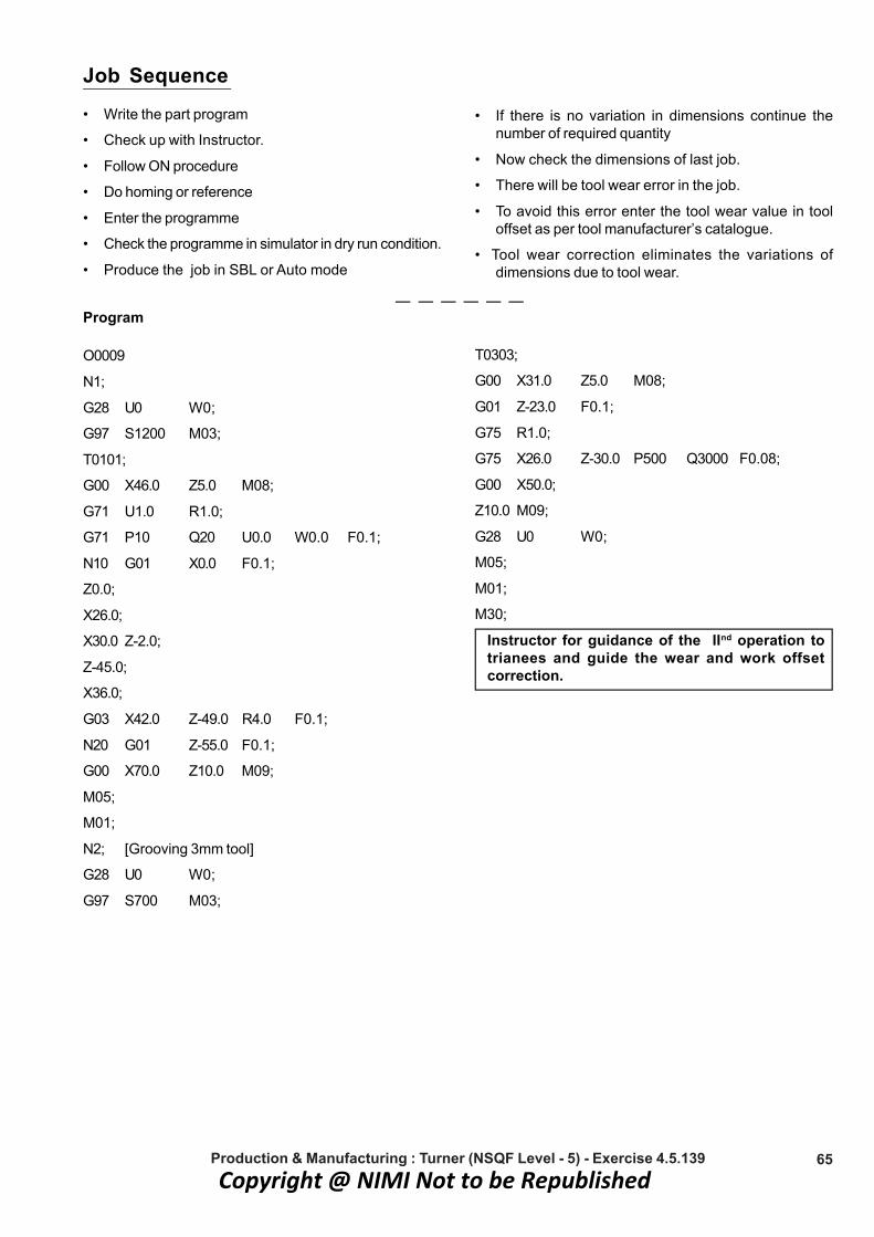
65
Job Sequence• Write the part program
• Check up with Instructor.
• Follow ON procedure
• Do homing or reference
• Enter the programme
• Check the programme in simulator in dry run condition.
• Produce the job in SBL or Auto mode
• If there is no variation in dimensions continue thenumber of required quantity
• Now check the dimensions of last job.
• There will be tool wear error in the job.
• To avoid this error enter the tool wear value in tooloffset as per tool manufacturer’s catalogue.
• Tool wear correction eliminates the variations ofdimensions due to tool wear.
Program
O0009
N1;
G28 U0 W0;
G97 S1200 M03;
T0101;
G00 X46.0 Z5.0 M08;
G71 U1.0 R1.0;
G71 P10 Q20 U0.0 W0.0 F0.1;
N10 G01 X0.0 F0.1;
Z0.0;
X26.0;
X30.0 Z-2.0;
Z-45.0;
X36.0;
G03 X42.0 Z-49.0 R4.0 F0.1;
N20 G01 Z-55.0 F0.1;
G00 X70.0 Z10.0 M09;
M05;
M01;
N2; [Grooving 3mm tool]
G28 U0 W0;
G97 S700 M03;
T0303;
G00 X31.0 Z5.0 M08;
G01 Z-23.0 F0.1;
G75 R1.0;
G75 X26.0 Z-30.0 P500 Q3000 F0.08;
G00 X50.0;
Z10.0 M09;
G28 U0 W0;
M05;
M01;
M30;
Instructor for guidance of the IInd operation totrianees and guide the wear and work offsetcorrection.
Production & Manufacturing : Turner (NSQF Level - 5) - Exercise 4.5.139Copyright @ NIMI Not to be Republished

66
Production & ManufacturingTurner - CNC Turning Operation Exercise 4.5.140
Produce components on CNC Machine involving different “Programmingfor turning OD,ID grooving operation turning operationObjectives : At the end of this exercise you shall be able to• write the part program for OD / ID cycles including drilling and boring operation• carryout threading in different pitches• set the machine with necessary tools• run the machine to produce the job.
Copyright @ NIMI Not to be Republished

67
I st operation05349
N1; [ Turning ]
G28 U0 W0;
G97 S1200 M03;
T0101;
G00 X50.0 Z5.0 M08;
G01 Z3.0 F0.1;
G71 U1.0 R1.0;
G71 P10 Q20 U0.0 W0.0 F0.1;
N10 G01 Z0.0 F0.1;
X12.0;
X16.0 Z-2.0;
Z-25.0;
X20.0
X24.0 Z-27.0;
Z-55.0;
X36.0;
G03 X40.0 Z-70.0 R2 F0.1;
G01 X46.0 Z-13.0 F0.1;
N20 G01 Z-75.0 F0.1;
G00 X60.0 Z10.0 M09;
G28 U0 W0;
M05;
M01;
N2; [ OD Grooving ]
G28 U0 W0;
G97 S700 M03;
T0303;
G00 X17.0 Z5.0 M08;
G01 Z-23.0 F0.1;
G75 R1.0;
G75 X13.5 Z-25.0 P500 Q2000 F0.08;
G00 X25.0;
G01 Z-44.0 F0.1;
G75 R10;
G75 X20.0 Z-45.0 P500 Q1000 F0.08;
G00 X50.0;
Z10.0 M09;
G28 U0 W0;
M05;
M01;
N3; (Threading)
G28 U0 W0;
G97 S600 M04;
T0505;
G00 X17.0 Z5.0 M08;
G01 Z3.0 F0.1; [ M16x1.5 ]
G92 X16.0 Z-22.0 F1.5;
X15.8;
X15.6;
X15.4;
X15.2;
X15.0;
X14.8;
X14.6;
X14.4;
X14.2;
X14.1;
X14.065;
14.065;
G00 X25.0;
Z-23.0; [ M24 x 2 ]
G76 P030060 Q300 R20;
G76 X21.42 Z-46.0 P1300 Q300 F2;
G00 X60.0;
Z10.0 M09;
G28 U0 W0;
M05;
M01;
M30;
IInd Operation Reverse the job in soft jawsclamping on Φ40
O5350;
N1;
G28 U0 W0;
G97 S1200 M03;
T0101;
G00 X55.0 Z5.0 M08;
G01 Z3.0 F0.1;
G71 U1.0 R1.0;
G71 P10 Q20 U0.0 W0.0 F0.1;
Production & Manufacturing : Turner (NSQF Level - 5) - Exercise 4.5.140Copyright @ NIMI Not to be Republished

68
N10 G01 X0.0 F0.1;
Z0.0;
X42.0;
X46.0 Z-2.0;
N20 G01 Z-40.0 F0.1;
G00 X60.0 Z10.0 M09;
G28 U0 W0;
M05;
M01;
N2; (Centre Drilling)
G28 U0 W0;
G97 S1800 M03;
T0202;
G00 X0 Z5.0 M06;
G01 Z-7.0 F0.1;
G00 Z10.0 M09;
G28 U0 W0;
M05;
M01;
N3; [φ 16 Drill ]
G28 U0 W0;
G97 S1000 M04;
T0404;
G00 X0.0 Z5.0 M08;
G74 R2.0;
G74 Z-55.0 Q1000 F0.1;
G00 Z10.0 M09;
G28 U0 W0;
M05;
M01;
N4; [ Boring Tool ]
G28 U0 W0;
G97 S1200 M03;
T0606;
G00 X15.0 Z5.0 M08;
G71 U0 R1.0;
G71 P30 Q40 U0.0 W0.0 F0.1;
N30 G01 Z-50.0 F0.1;
X16.0;
Z-38.0;
X21.42
Z-2.0;
X25.0 Z0.0;
N40 G01 Z2.0 F0.1;
G00 Z10.0 M09;
G28 U0 W0;
M05;
M01;
N5; (ID Grooving 2mm width)
G28 U0 W0;
G97 S600 M03;
T0707;
G00 X20.0 Z5.0 M08;
G01 Z-36.0 Z5.0 M08;
G75 R10.0;
G75 X20.0 Z-38.0 P400 Q2000 F0.08;
G00 X22.0;
Z10.0 M09;
G28 U0 W0;
M05;
M01;
N6 [ID Threading ]
G28 U0 W0;
G97 S600 M03;
T0808;
G00 X20.0 Z5.0 M08;
G76 P030060 Q200 R20;
G76 X24.0 Z-35.0 P13000 Q300 F2.0;
G00 X15.0;
Z10.0 M09;
G28 U0 W0;
M05;
M01;
M30;
Production & Manufacturing : Turner (NSQF Level - 5) - Exercise 4.5.140Copyright @ NIMI Not to be Republished

69
Production & Manufacturing Exercise 4.5.141Turner - CNC Turning Operation
Produce components by involving turning operation and part programmeObjectives : At the end of this exercise you shall be able to• write the part program for the given job in sinumeric control• input the part program into the machine and simulate the program• set the machine with necessary tools• run the machine to produce the job.
Copyright @ NIMI Not to be Republished

70
Job Sequence• Study the part drawing and list the tools required.
• Prepare the ‘CNC’ programme using simulator.
• Simulate and verify the programme in simulatorsoftware.
• Get it checked by the Instructor
• Check the raw materials size and confirm with thepart drawing.
• Hold the job on chuck by projecting 55mm length inturning
• Enter the part programme in CNC machine or transferthe programme by simulator to CNC machine.
• Set the tool to required turret station.
• Measure work offset in X and Z direction and enter thework offset page.
• Measure the tool offset all tools in X and Z directionenter the tool geometry offset page
• Enter the tool type and tool nose radius check theoffset and tool offset.
• If there is any mistake correct the programme askyour Instructor for guidance
• Run the program in single block by setting the offsetaway from the work zero
• Observe the spindle direction speed tool positioncarefully
• Run the programme in auto mode in original tool andworkset .
• Check the dimension if any correction change the wearoffset and run the programme.
• Check the dimension, and surface finish.
• Remove the job from the machine check all thedimension once again.
• Switch off the machine.
• Reverse the job in IInd operation
PART PROGRAM Ist OPERATION
%124
N1 G71 G90 G95;
N2 G00 G90 G53 X180 Z0;
N3 S1200 M03;
N4 T1 D1 M06;
N5 G00 X56 Z5 M08;
N6 R20=50 R21= 55 R22= 0 R24= 0.3 R25=0.1
R26=1 R27 =42 R28=0.1 R29=41 L95 P1;
N7 G00 X60 Z10 M09;
N8 D0;
N9 G00 G90 G53 X180 Z10 M09;
N10 M05;
N11 M01;
N12 G00 G90 G53 X180 Z0;
N13 S1800 M04;( Centre drill)
N14 T2 D0 M06;
N15 G00 X0 Z5 M08;
N16 G01 Z-7 F0.1;
N17 G00 Z10 M09;
N18 D0;
N19 G00 Z10 M09;
N20 M05;
N21 M01;
N23 G00 G90 G53 X180 Z0;
N24 S1200 M04;
N25 T4 D4 M06; ( Dia 16 Drill)
N26 G00 X0 Z5 M08;
N27 R 22 = 2 R 24 = 5 R 25 = 10 R 26 = - 78 R 27 =1R 8 = 1 L = 98 P1;
N28 G00 Z10 M09;
N29 D0;
N30 G00 G90 G53 X180 Z0;
N31 M05;
N31 M01;
N32 G00 G90 G53 X180 Z0;
N33 S1000 M03; (Boring)
N34 T3 D3 M06;
N35 G00 X15 Z5 M08;
N36 R20=100 R21 = 16 R22 = 0 R24 = 0.2 R25 =0.05 R26 = 0.5 R27 = 42 R28 = 0.1 R29 = 43L95 P1;N38 D0;
N37 G00 X60 Z10 M09;
N38 D0;
N39 G00 G90 G53 X180 Z0;
N40 M05;
N41 M01;
N42 M03;
Production & Manufacturing : Turner (NSQF Level - 5) - Exercise 4.5.141Copyright @ NIMI Not to be Republished

71
1 L 50 (OD Sub program )N5 G01 X0 F0.1;
N10 Z0;
N15 X46;
N20 X50 Z - 2;
N25 Z - 50;
N30 M17
2 L100(ID Sub Program)N5 G01 X34 F0.1;
N10 Z0;
N15 X30 Z - 2;
N20 Z - 25;
N25 X 20;
N30 Z - 75;
N35 M17;
PART PROGRAM IInd Operation% 125
N1 G71 G90 G95;
N2 G00 G90 G53 X180 Z0;
N3 S1200 M03;
N4 T1 D1 M06; [ TURNING TOOL ]
N5 G00 X55 Z5 M08;
N6 R20 = 150 R21 = 55 R22 = 0 R24 = 0.3 R 25 =0.1 R 26 = 1 R27 = 42 R28 = 0.1 R29 = 41 L95P1;
N7 G00 X60 Z5 M09;
N8 D0;
N9 G00 G90 G53 X180 Z0;
N10 M05;
N11 M01;
N12 G00 G90 G53 X180 Z0;
N13 S600 M03;
N14 T3 D3 M06;
N15 G00 X32 Z5 M08;
N16 G01 Z- 20 F 0.1;
N17 R 10 = 0 R21 = 31 R23 = -20 R23 = 0 R24 = 0.1R25 = 0.1 R 26 = 0.3 R27 =3 R28 = 1 R29 = 0R30 = 0 R31 = 26 R32 = 0 R 33 = 0 R 34 = 0R36 = 0 L93 P1;
N18 G00 X42;
N19 G01 Z -40;
N20 R 10 = 0 R21 = 41 R23 = - 40 R23 = 0 R24 = 0R25 = 0.1 R 26 = 0.3 R27 =3 R28 = 1 R29 = 0R30 = 0 R31 = 26 R32 = 0 R 33 = 0 R 34 = 0R36 = 0 L93 P1;
N21 G00 X60;
N22 G00 Z10 M09;
N23 D0;
N24 G00 G90 G53 X180 Z0;
N25 M05;
N27 M01;
N28 G00 G90 G53 X180 Z0;
N29 S600 M04;
N30 T5 D5 M06;
N31 G00 X31 Z5 M08;
N32 G01 Z3 F 0.1;
N33 R 20 = 1.5 R21 = 30 R22 = 0 R23 = 3 R24= -0.97R25 = 0.04 R 26 = 6 R27 =4 R28 = 5 R29 = 30R31 =28.07 R32 = -18 L97 P1;
N34 G00 X41;
N35 G01 Z-18 F0.1;
N36 R 20 =2 R21 = 40 R22 = - 20 R23= 4R24= -1.3R25 = 0.04 R 26 = 6 R27 =4 R28 = 6R29 =30R31 =37.42 R32 = -38 L97 P1;
N37 G00 X60;
N38 G00 Z10 M09;
N39 D0;
N40 G00 G90 G53 X180 Z0;
N41 M05;
N42 M01;
N43 M03;
L150 SUB PROGRAMN5 G01 X0 F0.1;
N10 Z0;
N15 X26;
N20 X30 Z-2;
N25 Z - 20;
N30 X 40;
N35 Z - 40;
N40 X50;
N45 Z - 55 ;
N50 M17;
Production & Manufacturing : Turner (NSQF Level - 5) - Exercise 4.5.141Copyright @ NIMI Not to be Republished

72
Production & Manufacturing Exercise 4.5.142Turner - CNC Turning Operation
Part off : Part programme in CNC machineObjectives : At the end of this exercise you shall be able to• write the part program for part of work• input the part program into the machine• set the machine with necessary tools• run the machine to produce the job.
Copyright @ NIMI Not to be Republished

73
Job Sequence• Study the part drawing
• Prepare the CNC program
• Get it checked by the instructor
• Hold the job on chuck by projection 60mm lengthin turning and part off.
ProgramO0010
N1 [ TURNING ]
G28 U0 W0;
G97 S1200 M03;
T0101;
G00 X30.0 Z5.0 M08;
Z0.0;
G01 X24.0 Z2.0;
G01 Z-55.0 F 0.1;
G00 X26.0 Z2.0;
X23.0;
G01 Z-55.0 F 0.1;
G00 X26.0 Z2.0;
X22.015;
G01 Z-55.0 F0.1;
G00 X30.0 Z5.0 M09;
G28 U0 W0;
M05;
• Enter the program
• Take the offset
• Run the program in auto mode
• Take the part off piece and check the dimension
• Remove the job and switch OFF the machine
M01;
N2; [ 3mm parting tool ]
G28 U0 W0;
G97 S600 M03;
T0303;
G00 X23.0 Z5.0 M08;
G01 Z-53.0 F0.1;
G75 R1.0;
G75 X-1.0 Z-50.0 P400 Q0 F0.1;
G00 X30.0;
Z10.0 M09;
G28 U0 W0;
M05;
M01;
M30;
Production & Manufacturing : Turner (NSQF Level - 5) - Exercise 4.5.142Copyright @ NIMI Not to be Republished

74
Job Sequence%
O4133;
N10 G21 G40 G90;
N15 G28 U0 W0;
N20 G50 S1500 T0101;
N 25 G96 S400 M03;
N30 G00 G42 X52 Z5;
N35 G71 U1 R2;
N40 G71 P45 Q80 U1 W1 F0.1;
N45 G01 X0 Z-0;
N50 G03 X20 Z-10 R10;
N55 G01 Z-25;
N60 G01 X30 Z-40;
N65 Z-60;
N70 G02 X46 Z-68 R8;
N75 G01 Z-108;
N80 G00 X50;
N85 G00 X60 Z20;
N90 G70 P45 Q80 F0.05;
N95 G00 X60 Z20 T0100 M09
N100 G28 U0 W0;
N111 M05;
N115 M30;
Production & ManufacturingTurner - CNC Turning Operation Exercise 4.5.143
Produce job involving profile Turning, Threading, Taper and BoringObjectives : At the end of this exercise you shall be able to• write the part program for the given sketch for FANUC controls• input the part program into the machine• produce the job in SBL/AUTO mode.
Copyright @ NIMI Not to be Republished

75
Job Sequence ( Common to TASK :1 & TASK : 2)
• Study the part drawing and list the tools required
• Preapre the CNC program.
• Get it checked by the instructor.
• Check the raw material size and conform with the partdrawing ,
• Hold the job on chuck by projection 55 mm length inturning.
• Enter the part rogramme in CNC machine (or) transferthe programme by simulator to CNC machine.
• Set the tool to the required turret station.
• Measure work offset in X and Z direction and enter thework offset page say G54/G55.
• Measure the tool offset in all tools in X and Z directionand enter the tool geometry offset page.
• Enter the tool type and tool nose radius
• Check the work offset and tool offset.
If there is any mistake correct the programmeask your instructor for guidance
• Run the programme in single block by setting the offsetaway from the work zero
• Observe the spindle direction speed tool positioncarefully.
• Run the programme in auto mode in original tool andwork set.
• Check the dimension. If any correction changes thewear offset and run the programme.
• Check the dimension and surface finish.
• Remove the job from the machine. Check all thedimension once again.
• Switch off the machine.
TASK 2 : Job Sequence (Common to Task 1 and Task 2) % (1 st Operation)O00125
N1;
G28 U0 W0;
G97 S1200M03;
T0101;
G00 X55.0 Z5.0 M08;
G71 U1.0 R1.0;
G71 P10 Q20 U0.0 W0.0 F0.1;
N10 G01 X0.0 F0.1;
Z0.0;
X48.0;
X50.0 Z-1.0;
N20 G01 Z-50.0 F0.1;
G00 X60.0 Z5.0 M09;
G28 U0 W0;
M05;
M01;
N2; (Centre Drill)
G28 U0 W0;
Production & Manufacturing : Turner (NSQF Level - 5) - Exercise 4.5.143Copyright @ NIMI Not to be Republished

76
G97 S1800 M04;
T0202;
G00 X0.0 Z5.0 M08;
G01 Z-7.0 F0.1;
G00 Z10.0 M09;
G28 U0 W0;
M05;
M01;
N3; ( 12 mm Drill)
G28 U0 W0;
G97 S1500 M04;
T0404;
G00 X0.0 Z5.0 M08;
G74 R2.0;
G74 Z-88.0Q1000F0.1;
G00 Z10.0 M09;
G28 U0 W0;
M05;
M01;
N4;
G28 U0 W0;
G97 S1000 M03;
T0606;
G00 X11.0 Z5.0 M08;
G71 U0.5 R1.0;
G71 P.30 Q40.0 U0.0 W0.0 F0.1;
N30 G01 X25.0 F0.1;
Z-50.0;
X40.0;
Z-1.0;
N40 G01 X42.0 Z0.0 F0.1;
G00 X10.0 Z5.0 M09;
G28 U0 W0;
M05;
M01;
M30;
Programme for Grooving threading & taper threadingO0126;
N1;
G28 U0 W0;
G97 S1200M03;
T0101;
G00 X55.0 Z5.0 M08;
G71 U10 R1.0;
G71 P10 Q20 U0.0 W0.0 F0.1;
N10 G01 X0.0 F0.1;
Z0.0;
X26.0;
X30.0 Z-2.0;
Z-25.0;
X40.0 Z-55.0;
N20 G01 Z-65.0 F0.1;
G00 X60.0 Z5.0 M09;
G28 U0 W0;
M05;
M01;
N2; (Grooving 3mm)
G28 U0 W0;
G97 S600 M03;
T0303;
G00 X31.0 Z5.0 M08;
G01 Z-31.0Z5.0 M08;
G75 R1.0;
G75 X26.0 Z-25.0 P600 Q2000 F0.08;
G00 X60.0;
Z10.0 M09;
G28 U0 W0;
M05;
M01;
N3; (Threading)
G28 U0 W0;
G97 S600 M04;
T0505;
G00 X31.0 Z5.0 M08;
G01 Z3.0 F0.1;
G76 P030060 Q150 R20;
G76 X27.42 P13000 Q300 F2.0;
G00 X60.0;
G01 Z-22.0 F0.1;
G76 P030060 Q100 R20;
G76 X51.25 Z-35.0 P0975 Q200 R-5.5 F1.5;
G00 X60.0 Z5.0 M09;
G28 U0 W0;
M05;Production & Manufacturing : Turner (NSQF Level - 5) - Exercise 4.5.143
Copyright @ NIMI Not to be Republished

77
M01;
M30;Calculate R parameter for tapered threadingon FANUC with G76 threading cycle.R = (Start Diameter - End Diameter) / 2
Production & Manufacturing : Turner (NSQF Level - 5) - Exercise 4.5.143Copyright @ NIMI Not to be Republished

78
Production & Manufacturing Exercise 4.5.144Turner - CNC Turning Operations
Demo on machine Bar Feeding System (Video)Objectives : At the end of this exercise you shall be able to• understand the bar feeding system• understand bar movement holding.
• Reduce the machine tool operator’s time and effortby auto feeding raw material.
• Support bar stock to reduce vibrations that cantransfer to the cutting zone and create dimensionand surface finish problems.
• Enable the machine tool to operate at optimumspindle speeds.
• Minimise change -over times.
• Reduce material wastage.
• Provide consistent, reliable operation that enableshigher volume of production.
The instructor guide to trainee on website inthe revelent bar feeding work in CNC M/C(video)
Copyright @ NIMI Not to be Republished

79
Optional
Instructor to arrange a visit to an industry, where the bar feedingfacility is available, to collect details on bar feeding system
(Or alternately)
Arrange video clipping of bar feeding mechanism, and CNCmachines, using bar feeding to get the trainees acquainted with thetechnology
Guide the trainees to prepare a flow diagram collect sketch of a barfeeding a system from the networking
Instructor to explain through a chart/photograph
Production & Manufacturing : Turner (NSQF Level - 5) - Exercise 4.5.144Copyright @ NIMI Not to be Republished

80
Production & ManufacturingTurner - CNC Turning Operations Exercise 4.5.145
DNC System Setup (Optional)Objectives : At the end of this exercise you shall be able to• setup Direct numerical control.
Direct numerical control (DNC) also known as distributednumerical control (also DNC) is a common manufactruingterm for networking CNC machine tools. On some CNCmachine controllers, the available memory is too smallto contain the machining program (for example machiningcomplex surface), so in this case the program is storedin a separate computer and sent directly to the machine,one block at a time. If the computer is connected to anumber of machines it can distribute programs to differentmachine as required. Usually, the manufacture of thecontrol provides suitable DNC software. However, if thisprovision is not possible, some software companiesprovide DNC applications that fulfill the purpose. DNCnetworking or DNC communication is always requiredwhen CAM programs are to run on some CNC machinecontrol.
Wireless DNC is also used in place of hard- wiredversions.Controls of this type are very widely used inindustries with significant sheet metal fabrication ,suchas the automotive, appliance and aerospace industries.
Job sequence
[ Learn thro instructor by viewing videos of DNCsystem]
Switch computer
Select Google website
Select DNC setup
View the video on DNC system
Record the observations
Discuss with yon instructor on transfer ofcommand eic.
Copyright @ NIMI Not to be Republished

81
Production & ManufacturingTurner - CNC Turning Operations Exercise 4.5.146
Run the Machine on DNC mode (Optional)Objectives : At the end of this exercise you shall be able to• run the machine in DNC mode.
Copyright @ NIMI Not to be Republished

82
When executing a program from with in the machine’smemory the operator can simply scan within the program(in the edit mode) to the restart command. When theyexecute the program, the machine will begin executingfrom the restart command.
However with direct numerical control there is no wayscan to the restart command form the control panel the(program resides in a computer outside the machine tool.)It can be cumber some (or impossible) to command theDNC system to begin sending the program from a specifiedcommand (though some DNC system make it easy to doso).
The program restart function of the CNC control allowsthe operator to specify the sequence number (N word)from which the control will begin executing the program.While the operator must of course, know this sequencenumber, the control will ignore all commands it sees inthe program until the restart command sequence numberis found.
Then it will begin executing the programme.
Production & Manufacturing : Turner (NSQF Level - 5) - Exercise 4.5.146Copyright @ NIMI Not to be Republished

83
Production & ManufacturingTurner - CNC Turning Operations Exercise 4.5.147CAM Programme Execution (Optional)Objectives : At the end of this exercise you shall be able to• execute the CAM programme• get awarness on PLM concept.
CAD / CAM EXECUTION
CAD / CAM Software generate tool path that drive the machine tools
to turn the Design into a finished product.
CAM Software covers :Includes process WIZARDS
Templates
Libraries
Specific function interfaces
CAM - Design output / PLM Codes CNC Machine
- Support window system
To design a product
To manufactrue a product thro a CNC machineoperator thro’ CAD output
(Design / drafting arrangement)
Copyright @ NIMI Not to be Republished

84
Skill SequenceCAM , Computer Aided Manufacturing is a techinique usingNC programming tool by which 2D / 3D models ofcomponents can be generated using CAD. This techniquedoes not eliminate the human resources like skilledprofessional engineers, machinists, NC programmers etc,but leverages the value of skillled professinals thro’ theuse of advanced productivity tools. It also enables buildingthe skill of engineers thro’ Visualisation, simulation &optimisation of all resources.
Ease in usages : For the beginners using CAM the processWizards Templates, Liabraries, Specific function interfaceCAM build’s user confidence and increase the speed oflearning with ease.
Complexity in ManufacturingThe manufacturing environment, ,namely machineoperation, process, limitations, etc, are becoming morecomplex in modern times. Hence the need arises, to useautomised tools. The modren day machines cannot beeffectively used unless the engineers / operators areknowledgeable with computer and numerical basedapplications such as CAM /PLM etc..,
Specialised turning operation, 5axis machining, laser /plasma cutting wire EDM all essentially needs CADsystem.
Using CAM it is possible to streamline and create anycomplicated toolpath highest feed rate with optimised toolaxis till best surface finish longer life for the tool etc, throughtailor made software programes.
There is a high level of intergration with PLM not onlymanufacturing but also the field support of the finishedproduct. Modern day multi - CAD solution ensures theease of operation and are scalable.
CAM helps even in part planning documentation for theshop floor, for the inspection wing resource management,data management, tool mangement etc are made feaxible.
Production & Manufacturing : Turner (NSQF Level - 5) - Exercise 4.5.147Copyright @ NIMI Not to be Republished

85
Production & ManufacturingTurner - CNC Turning Operations Exercise 4.5.148
DATA Input - Output on CNC MachineObjectives : At the end of this exercise you shall be able to• data input and output practice of CNC machine.
Input Output (Thorugh - CNC)
Keyboard G - Codes
Mouse M - Codes
USB Other Commands
Type of tool Hand written - highly optimised‘G’ codes
Tool path
CAMCAM
Skill SequenceData Input - output on CNC
CAM software provides comprehensive & intergrated NCprogramming capabilities in a single system enabling theuse of 3D model,data, process planning etc, reducescycletime, high volume production & to make better partsfaster, through digital transformation.
CAD/ CAM system facilitate communication betweendesigner, manufacturer etc.,
Data Input : are generally commands that we enterthrough a key board, mouse, USB storage device etc,called on input devices.
G - Codes are the set of commands for each machinetool for machine flexibility. The direct input command fromCAD system may not be acceptable to CNC machine.
CAD operator export data format in the form of IGES,STL, Parasolid supported by a suitable software.
The output from CAM software is usually G - code / M -code and varieties of other commands transfered to amachine tool using DNC programe through’s USB storagedevice.
Replacing a printed circuit board may require re-settingdata. The boot systems can be used to save and restoreall SRAM data in one lump.
Input & output of data is done through the following steps
1 Setting parameters for input/output (using soft key(OPRT), parameters added/input from reader)
2 Inputting/outputting data (confirming the parametersrequired for data input/output, selection I/O channeletc)
3 Outputting CNC parameters
4 Outputting pitch error compensation amount
5 Outputting customs macro variable values
6 Outputting tool compensation amount
7 Outputting part program
8 Inputting CNC parameter
9 Inputting serial no 4,5,6 & 7.
Copyright @ NIMI Not to be Republished

86
Production & ManufacturingTurner - Advanced Turning Exercise 4.6.149
Thread on taper surface (Vee form)Objectives : At the end of this exercise you shall be able to• set the job to centre drill• grind and set the threading tool• set the tail stock off-set & cut taper thread.• manufacture male and female component as per drawing.
Copyright @ NIMI Not to be Republished

87
Job sequenceTASK 1 : (External thread)
• Check the raw material for its size.
• Hold the job in the 4 jaw chuck and true it.
• Finish facing on the end.
• Centre drill the work.
• Reverse the job hold in the chuck and true it.
• Face and maintain to the required total length of150 mm.
• Centre drill the outer end of work.
• Loosen and remove the job and dismount from fourjaw chuck.
• Prepare the job to turn between centres and align thecentres.
• Hold the job between centre.
• Turn the dia 32 mm to a length of100 mm.
• Reverse the job and fix again between centre to turnremaining length to dia 30 mm.
• Set the under cut tool.
• Turn undercut dia 25 x 10 mm length as per drawing.
Tan φ
50x242.547.5
2ldD
−=
−=
1005
= = 0.05
• Calculate the tail stock offset by using formula.
= 3.75 mm25
100150
x25
100150
x2
2530
==
−
x23
415
Offset the tailstock to 3.75 mm towards the operator.Turnthe taper as per dimension. Set the threading tool. Setthe change gears for 2 mm pitch.
DrivenDriver
8040
2020
x42
DrivenDriver
lead screwPitch of acut be to Pitch
−=
=
• Cut the taper thread.• Remove the burrs.
TASK 2 : Job sequence (Internal thread)
• Check the raw material for its size.
• Hold the job in a four jaw chuck and true it.
• Set the tool for facing.
• Face one end and turn ∅60 mm for maximum length.
• Reverse the job, hold in the chuck and true it.
• Face and turn to maintain total length 50 mm and ∅60mm.
• Drill dia 10 mm through hole.
• Enlarge the through hole to ∅25 mm.
• Fix the boring bar in the tool post and finish bore dia 40mm.
• Taper calculation.
• Set the natural tangent value 2º 52'
• Set the taper turning attachment for the 2º52' amountof taper.
• Taper bore by engaging the power feed for a totallength.
• Complete the taper boring.
• Set the change gear and norton gear box lever positionfor thread to 2 mm pitch.
• Cut the taper thread.
• Remove burrs.
• check for the assembly.
Production & Manufacturing : Turner (NSQF Level - 5) - Exercise 4.6.149Copyright @ NIMI Not to be Republished

88
Production & ManufacturingTurner - Advanced 051.6.4 esicrexEgninruT
Manufacturing & assembly of Screw Jack by performing different latheopreations.Objectives: At the end of this exercise you shall be able to• set the job in between centres• set the thread cutting tool & grind the grooving tool• cut the external thread• assemble screw jack with the machined components.
Fig 1
Copyright @ NIMI Not to be Republished

89
Job sequenceTASK : 1
• Check the raw material for its size.
• Hold the job in the independent chuck and true it withthe help of a surface gauge.
• Set the facing tool and face one end; centre drill thejob.
• Reverse and true it in an independent chuck and facethe job and maintain 62 mm length and centre drill theother end.
• Dismantle the chuck from the lathe spindle and fix thedriving plate on the spindle.
• Clamp the job to a straight lathe carrier and hold thejob between the live centre and the dead centre. Usegrease on the centre before fixing.
• Set the R.H turning tool and turn � 28 x 17 mm lengthand step turn � 18 mm for 10 mm length.
• Set the diamond knurling tool and knurl to � 28mm.
While knurling, select a slow spindle speed.
• Set the chamfering tool and chamfer 1 x 45° at knurleddiameter.
• Hold the job on � 18 mm with carrier and prepare forturning in between centres.
• Set the R.H turning tool and turn � 18 mm for 45 mmlength and step turn � 12 mm for 42 mm length.
• Set the grooving tool and form a groove to a depth ofcore dia minus 0.2 mm for 2.5 mm width.
• Set the chamfering tool and chamfer 1 x 45° on theknurled diameter.
• Also chamfer the end 1.5 x 45° on � 12 mm.
• Set the thread-cutting tool and set the change geartrain to cut M12 thread.
• Cut thread by the plunge cut method giving successivecuts.
• Check the workpiece with a precision measuringinstrument and check the thread by a standard M12thread ring gauge for a proper fit.
TASK 2 : ( Scraw jack Base stand)• Check the raw material for its size. (� 56 x 80)
• Hold the job in a 4 jaw chuck keeping 25 mm lengthoutside the chuck, and true the job with a surfacegauge.
• Set the facing tool in the tool post to correct centreheight and face one end.
Production & Manufacturing : Turner (NSQF Level - 5) - Exercise 4.6.150
• Centre drill on the faced end of the job, through hole
• Drill the job to a core diameter of 10.25 mm for M12tapping.
• Enlarge the drilled hole with a 18 mm diameter drill startthe face end to 55 mm deep.
Copyright @ NIMI Not to be Republished

90
TASK 3 : Screw Jack Base (fig 2)
• Check the given raw material for its size. (� 85 x 20)
• Clamp firmly the facing tool, turning tool, boring tool andform tool in a four way tool post to correct centre heightwith minimum overhang.
• Hold the raw material in a four jaw chuck about 12 mmoutside and true.
• Face the work, set the machine to the calculatedspindle speed.
• Turn outer dia 80 mm to the maximum possible length.
• Make Centre drill and then pilot drilling with a � 12 mmdrill and enlarge it by � 18mm by drilling through using18mm drill.
• Bore to � 20.2 mm through.
• Step bore � 65 mm to a depth of 3 mm.
• Keep thecarriage in a locked position and eliminate thebacklash of the slides, before feeding the tool to thework.
• Swivel the compound slide to 45° and chamfer the bore� 20.2 mm, for 1 mm.
• Reverse the job and hold it on � 80 mm on protectiveshims, and true the dia and inner surface.
• Face the work to maintain a length of 11 mm.
• Form a 5 mm radius with a form tool.
• Bore � 60 H7 for 2 mm deep.
• Fix a face grooving tool of 2 mm width, with the cuttingedge parallel to the work surface.
• Touch the cutting edge to the work, face and set thegraduated collar of the top slide to zero.
Production & Manufacturing : Turner (NSQF Level - 5) - Exercise 4.6.150
• Set the R. H. Turning tool and turn � 50mm to 25mmlength.
• Reverse and hold the job in a 4 jaw chuck keeping65 mm length outside the chuck, and true the job witha surface gauge.
• Set the facing tool, and face to maintain a length of 75mm.
• Set the right hand turning tool, and turn � 50 mm to theleft, over the length of the job.
• Set the R.H. turning tool, and form step � 18 x 3 mmlength.
• Swivel the compound slide to 10° and turn taper to alength 60 mm from the face.
• Set the chamfering tool and form chamfer 2 x 45° at thesmall end of the taper.
• Chamfer the tapping hole with a � 12 mm drill for 1.5 mmdeep.
• Form internal threads M12 by tapping with a M12 tapset.
• Check the sizes with precision measuring instruments.
• Check threads with a M12 standard plug gauge.
Copyright @ NIMI Not to be Republished

91
TASK 4 : Screw Jack body ( fig 3)
• Keep the spindle speed to about 50 r.p.m
• Position the tool by the cross-slide movement to havethe cutting edge bore surface reference at 20 mm.
• Feed the tool by the compound slide for 3 mm deep toform the face groove.
• Keep the carriage locked till the face grooving operationis completed.
• Deburr the sharp edges.
• Check the raw material for its size. ( � 65 x 63)
• Fix the facing tool, turning tool, form tool and boring toolin a four way tool post to the correct centre height withthe minimum overhang.
• Hold the raw material in a four jaw chuck and true it.
• Select and set a suitable spindle speed.
• Finish face the overhanging end.
• Reverse and face the work to maintain a total length of58 mm.
• Centre drill, pilot drill with a � 10 mm drill and enlarge to� 18 mm by drilling.
• Bore through hole to � 19.7 mm.
• Chamfer the bored hole 1x45º, and ream � 20mm through hole.
• Mount the work on a mandrel and secure it by a nut andwasher.
• Remove the chuck from the main spindle and mount adriving plate.
• Hold the mandrel with the work in between centres.
• Rough and finish turn outer dia 60 mm.
• Swivel the compound slide to 15º and turn taper.
• Step groove for 10 mm width for 2 mm deep with a R2radius form tool.
• Deburr the sharp edges.
Production & Manufacturing : Turner (NSQF Level - 5) - Exercise 4.6.150
TASK 5 : Screw Jack spindle ( fig 4)• Check the raw material for its size. ( � 36 x 90)
• Clamp the facing tool, turning tool, form tool, squarethread cutting tool in a four way tool post to the correctcentre height with the minimum overhang.
• Hold the material in a 4 jaw chuck 30 mm outside andtrue it, select and set the spindle speed.
• Face the overhanging end and turn outer dia31.8 mm tothe maximum possible length.
Copyright @ NIMI Not to be Republished

92
• Turn step � 28 mm to a length of 10 mm.
• Swivel the compound slide to 60° and turn taper to 120°point.
• Clamp the knurling tool in the tool post and knurl the jobby plunging to get an outer diameter 32 mm
• Reverse the job and hold on the knurled portion byprotective shims.
• Face the overhanging end to maintain the total length of87 mm.
• Centre drill and support with the centre.
• Step turn � 23 mm to 65 mm length.
• Finish turn � 23 mm to � 22 mm and simultaneouslyform radius R2, on the turning length 67 mm.
• Step turn � 20 mm to a length of 62 mm and turn step� 15 mm to a length of 3 mm.
• Chamfer the thread end 2 x 45°.
• Form an undercut to a width of 5 mm and R2 maintainthe undercut dia 15.4 mm. Set the R.H.Sq. threadingtool in the tool post to centre height and the cuttingedge parallel to the job axis.
• Set the change gears in Norton gear box lever positionfor thread cutting of 4 mm pitch R.H. thread.
• Cut square threads SQ 20 x 4 to 54 mm length.
• Remove the sharp edges.
Production & Manufacturing : Turner (NSQF Level - 5) - Exercise 4.6.150Copyright @ NIMI Not to be Republished
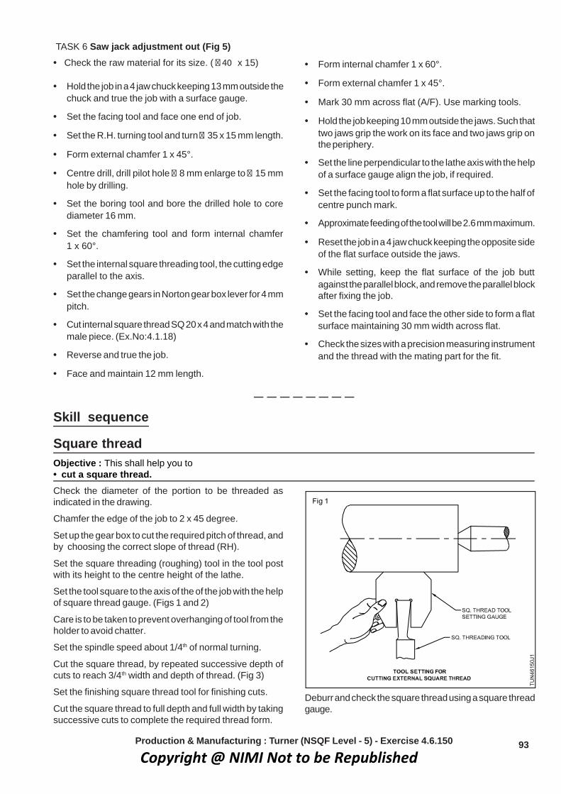
93
TASK 6 Saw jack adjustment out (Fig 5)• Check the raw material for its size. ( � 40 x 15)
• Hold the job in a 4 jaw chuck keeping 13 mm outside thechuck and true the job with a surface gauge.
• Set the facing tool and face one end of job.
• Set the R.H. turning tool and turn � 35 x 15 mm length.
• Form external chamfer 1 x 45°.
• Centre drill, drill pilot hole � 8 mm enlarge to � 15 mmhole by drilling.
• Set the boring tool and bore the drilled hole to corediameter 16 mm.
• Set the chamfering tool and form internal chamfer1 x 60°.
• Set the internal square threading tool, the cutting edgeparallel to the axis.
• Set the change gears in Norton gear box lever for 4 mmpitch.
• Cut internal square thread SQ 20 x 4 and match with themale piece. (Ex.No:4.1.18)
• Reverse and true the job.
• Face and maintain 12 mm length.
• Form internal chamfer 1 x 60°.
• Form external chamfer 1 x 45°.
• Mark 30 mm across flat (A/F). Use marking tools.
• Hold the job keeping 10 mm outside the jaws. Such thattwo jaws grip the work on its face and two jaws grip onthe periphery.
• Set the line perpendicular to the lathe axis with the helpof a surface gauge align the job, if required.
• Set the facing tool to form a flat surface up to the half ofcentre punch mark.
• Approximate feeding of the tool will be 2.6 mm maximum.
• Reset the job in a 4 jaw chuck keeping the opposite sideof the flat surface outside the jaws.
• While setting, keep the flat surface of the job buttagainst the parallel block, and remove the parallel blockafter fixing the job.
• Set the facing tool and face the other side to form a flatsurface maintaining 30 mm width across flat.
• Check the sizes with a precision measuring instrumentand the thread with the mating part for the fit.
Production & Manufacturing : Turner (NSQF Level - 5) - Exercise 4.6.150
Skill sequence
Square threadObjective : This shall help you to• cut a square thread.Check the diameter of the portion to be threaded asindicated in the drawing.
Chamfer the edge of the job to 2 x 45 degree.
Set up the gear box to cut the required pitch of thread, andby choosing the correct slope of thread (RH).
Set the square threading (roughing) tool in the tool postwith its height to the centre height of the lathe.
Set the tool square to the axis of the of the job with the helpof square thread gauge. (Figs 1 and 2)
Care is to be taken to prevent overhanging of tool from theholder to avoid chatter.
Set the spindle speed about 1/4th of normal turning.
Cut the square thread, by repeated successive depth ofcuts to reach 3/4th width and depth of thread. (Fig 3)
Set the finishing square thread tool for finishing cuts.
Cut the square thread to full depth and full width by takingsuccessive cuts to complete the required thread form.
Deburr and check the square thread using a square threadgauge.
Copyright @ NIMI Not to be Republished
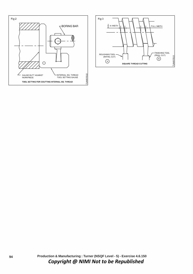
94 Production & Manufacturing : Turner (NSQF Level - 5) - Exercise 4.6.150
Copyright @ NIMI Not to be Republished
95
Job sequence• Study the different types of documentation provided
(format).
• Visit to industry and collect the input/ information fromindustry and fill it up of all the format.
• Prepare the required format with the knowledge gainedduring the industrial visit.
• Record relevant information in the format.
• Get it checked by your instructor/ Training Officer.
Note:• Instructor / Training Officer should arrange for
a industrial visit near by your institute, collectinputs and fill up format as required.
• Trainees will be guided by the concernedinstructor/ TO.
• Collect necessary information forms and instructthe trainees to reproduce the forms and guidethem in Documentation
Production & Manufacturing151.6.4 esicrexEgninruT decnavdA - renruT
Prepare differnet type of Documentations and methods of recordinginformationObjectives : At the end of this exercise you shall be able to• prepare and fill up batch processing record format• prepare and fill up bill of materials (BOM)• prepare and fill up production cycle time format• prepare and fill up daily production report format• prepare and fill up manufacturing stage inspection report format.
Copyright @ NIMI Not to be Republished

96 Production & Manufacturing : Turner (NSQF Level - 5) - Exercise 4.6.151
Flow chart
Collect all documentation formats
Collect details & prepare BPR
Collect details of material, quality required, drawingReference and prepare BOM
Collect operation sequences, lowest repeatable timemachine cycle time & prepare. production cycle time
chart
Collect daily production detail, for all productionprocess/products and prepare daily production report
Collect product code, components inspected, quantityaccepted/rejected , prepare manufacturing stage
inspection reports
Copyright @ NIMI Not to be Republished

97
BATCH PROCESSING RECORD - FORMAT - 1
Batch Processing Record
: .on hctaBboj fo noitpircseD
: ytitnauq hctaB: .on traP
: .on drocer hctaB: trap fo emaN
Purchase order no. :
Description of process :
Manufacturing Organisation :
Period of manufacture (Year - Qtr): Start date of manufacture: End date of manufacture:
Number of pages according to batch: Inserted pages: Manufacturing facilities:
Total number of pages
1. Operator / Technicianerutangis dna emaNetaD
2. Production in-charge:erutangis dna emaNetaD
3. Section managererutangis dna emaNetaD
4. Plant in-charge:erutangis dna emaNetaD
5. Production managererutangis dna emaNetaD
Remarks (if any)
Production & Manufacturing : Turner (NSQF Level - 5) - Exercise 4.6.151Copyright @ NIMI Not to be Republished

98
S. No. Item No. Description Quantity Reference Material as Remarks dwg no. per standard
BILL OF MATERIAL (BOM)- FORMAT-2(as per IS: 11666 - 1985)
Date:
Place: Incharge
Production & Manufacturing : Turner (NSQF Level - 5) - Exercise 4.6.151Copyright @ NIMI Not to be Republished

99
PRODUCTION CYCLE TIME - FORMAT-3
Organisation Name: Process: Line Incharge: Date/Time:
Department / Section:
gninihcaM :rotarepO Cycle Notes Time
Operations Sequence Observed Time Lowest Repeatable
Production & Manufacturing : Turner (NSQF Level - 5) - Exercise 4.6.151Copyright @ NIMI Not to be Republished

100
Dai
ly P
rodu
ctio
n R
epor
t
Dat
e:D
epar
tmen
t:O
rgan
isat
ion
Nam
e:
Sect
ion:
DA
ILY
PRO
DU
CTI
ON
REP
OR
T - F
OR
MA
T- 4
Pro
cess
- I
Proc
ess-
IIPr
oces
s-III
Proc
ess-
IV
Q
ualit
y C
ontro
l
P
acki
ng
Plan
ned
Com
plet
edPl
anne
dC
ompl
eted
Plan
ned
Com
plet
edPl
anne
dC
ompl
eted
Plan
ned
Com
plet
edPl
anne
dC
ompl
eted
Job
Ord
er N
o.Q
uant
ityM
ater
ial &
Siz
e
Job
Ord
er N
o.Q
uant
ityM
ater
ial &
Siz
e
Job
Ord
er N
o.Q
uant
ityM
ater
ial &
Siz
e
Job
Ord
er N
o.Q
uant
ityM
ater
ial &
Siz
e
Job
Ord
er N
o.Q
uant
ityM
ater
ial &
Siz
e
Sign
atur
e of
sec
tion
Inch
arge
Production & Manufacturing : Turner (NSQF Level - 5) - Exercise 4.6.151Copyright @ NIMI Not to be Republished

101
MA
NU
FAC
TUR
ING
STA
GE
INSP
ECTI
ON
REP
OR
T - F
OR
MA
T-5
....../...../.... etaD oT ....../...../.... eta
D morF :sutatS
:ema
N noitasinagrO D
epar
tmen
t / S
ectio
n:
Dat
ePr
oduc
t ID
/C
usto
mer
P.O
. No.
Job
J.
O.
Proc
ess
Qty
Acce
pted
Rej
ecte
d In
spec
tion
Rec
ord
No.
In
spec
tion/
Tes
t con
duct
ed b
yeta
D & eta
D .oN redr
O etaD &
edoC
Production & Manufacturing : Turner (NSQF Level - 5) - Exercise 4.6.151
Copyright @ NIMI Not to be Republished

102
Documentations - 2Objectives : At the end of this exercise you shall be able to• prepare and fill job card format• prepare and fill activity log format• prepare and fill batch production record• prepare and fill estimation sheet• prepare and fill maintenance log format• prepare and fill the history sheet of machinery and equipment format• prepare and fill maintenance record.
Flow diagram
Collect work order of each customer, and collect theproduction details everyday and fill in job cod
Ascertain time taken for the production everyday
Collect the operation on each component and collectthe performance and the machine used for each
operation
Prepare batch production record and observe thedeviation in each activity
Collect the detail of daily production, machineryutilisation & prepare work activity document.
Collect break down details and prepare maintenance logsheet
Prepare the check list for all the machines and preparepreventive maintenance record
Copyright @ NIMI Not to be Republished

103Production & Manufacturing : Turner (NSQF Level - 5) - Exercise 4.6.151
Job sequence• Study the different types of documentation provided
(format).
• Visit industry and collect the input / information fromindustry and fill it up in all the format.
• Prepare the required in format with the knowledgegained during the industrial visit.
• Record relevant information in the format.
• Get it checked by your instructor/ Training Officer.
Note:• Instructor / Training Officer should arrange
for a industrial visit near by your institute,collect inputs and fill up format as required.
• Trainees will be guided by the concernedinstructor/ TO.
• Collect necessary information forms andinstruct the trainees to reproduce the formsand guide them to fill it up.
JOB CARD - FORMAT-1
Doc No.
Job Card Rev No.
Date
Order Starting Date
Customer
Work Order No.
Details
S.No. Date Production Line Time (Minutes) Location Remarks Description Start Time End Time Total Time Time
Copyright @ NIMI Not to be Republished

104
WORK ACTIVITY LOG - FORMAT-2
Organisation Name:
Department:
Section:
Employee Name:
Supervisor Name:
Date:
Start / Stop Operations Equipment / Machinery/ Remarksperformed Instruments used
8.00 to 9.00 a.m.
9.00 to 10.00 a.m.
10.00 to 11.00 a.m.
11.00 to 12.00 noon
12.00 to 1.00 p.m.
1.00 to 2.00 p.m.
2.00 to 3.00 p.m.
3.00 to 4.00 p.m.
4.00 to 5.00 p.m.
5.00 to 6.00 p.m.
Production & Manufacturing : Turner (NSQF Level - 5) - Exercise 4.6.151Copyright @ NIMI Not to be Republished

105
BATCH PRODUCTION RECORD - FORMAT-3
Batch Production Record in accordance with batch processing record
Manufacturing Organisation Name: _______________________
Description of job: ______________________
Name of part: __________________________
Batch No.: ____________________________
The following deviations have appeared (continued)
No. process Name of processing step Document Short descriptionnoitaived fo .on egap pets
1 Raw material preparation:
_____________ .1_____________ :1 noitarepO
_____________ .2_____________ :2 noitarepO
_____________ .3_____________ :3 noitarepO4. _____________
2 Sizing of material:
_____________ .1_____________ :1 noitarepO
_____________ .2_____________ :2 noitarepO3. _____________
Production & Manufacturing : Turner (NSQF Level - 5) - Exercise 4.6.151Copyright @ NIMI Not to be Republished

106
ESTIMATION SHEET - FORMAT-4
Part Name: ___________________ Part No.: _____________ Part Drawing
Assembly: _________________ Material: ______________
Assembly No.: ______________ Stock size: ____________
Operation Operation Machine Estimated Rate / piece Tools noitpircsed.oN time per hr.
Prepared by: ________ Date: _________
Approved by: ________
Production & Manufacturing : Turner (NSQF Level - 5) - Exercise 4.6.151
Copyright @ NIMI Not to be Republished

107
MAINTENANCE LOG - FORMAT-5
S. No. Date Nature of fault Details of rectification Signature of in-charge done
Organisation Name :
Department :
Section :
Name of the machine :
Production & Manufacturing : Turner (NSQF Level - 5) - Exercise 4.6.151
Copyright @ NIMI Not to be Republished

108
MACHINERY AND EQUIPMENT RECORD - FORMAT-6
Organisation Name :
Department :
Section :
History sheet of machinery & Equipment
Description of equipment
Manufacturer’s address
Supplier’s address
Order No. and date
Date on which received
Date on which installed and placed
Date of commissioning
Size: Length x Width x Height
Weight
Cost
Motor particulars Watts/H.P./ r.p.m: Phase: Volts:
Bearings/ spares/ record
Belt specification
Lubrication details
Major repairs and overhaulscarried out with dates
Production & Manufacturing : Turner (NSQF Level - 5) - Exercise 4.6.151
Copyright @ NIMI Not to be Republished

109
PREVENTIVE MAINTENANCE RECORD - FORMAT-7
Organisation Name :
Department :
Section :
Name of the Machine : Location of the machine :
Machine Number :
Model No. & Make :
Check list for machine inspection
Inspect the following items and tick in the appropriate column and list the remedial measures for thedefective items.
Items to be checked Good working/ satisfactory Defective Remedial measures
Level of the machine
Belt/chain and its tension
Bearing condition (Look, feel,listen noise)
Driving clutch and brake
Exposed gears
Working in all the speeds
Working in all feeds
Lubrication and its system
Coolant and its system
Carriage & its travel
Cross-slide & its movement
Compound slide & its travel
Tailstock’s parallel movement
Electrical controls
Safety guards
Inspected by
Signature
Name:
Date: Signature of in-charge
Production & Manufacturing : Turner (NSQF Level - 5) - Exercise 4.6.151
Copyright @ NIMI Not to be Republished

110
Production & Manufacturing251.6.4 esicrexEgninruT decnavdA - renruT
Turn bevel gear blankObjectives: At the end of this exercise you shall be able to• turn the bevel gear blank and maintain the shape and dimensions• turn taper by compound slide method.
Copyright @ NIMI Not to be Republished

111
Job sequence• Check the raw material size.
• Hold the job in 4 jaw chuck and true it.
• Face the one end.
• Turn � 42 mm 25 mm length.
• Form radius with 5mm filleted tool at the edges 30 mmlength by turning the step 40 mm.
• Centre drill the job.
• Drill a pilot hole with a � 12 mm drill bit.
• Enlarge the hole with a � 20 mm drill.
• Bore the drilled hole to � 23.75 mm.
• Chemfer the edge of the hole 2 x 45º.
• Ream the bored hole with a machine reamer � 24 H9.
• Reverse the job and reset it by holding on � 40 mm.
• Face the other end to maintain 50 mm lengh.
• Set compound slide 50o and boring of taper with formof 5 mm radius end of reamed hole.
• Chamfer the reamed hole 2 x 45o.
• Mount the job on the mandrel along with bush and nut.
• Hold the mandrel between the centres.
• Turn � 79.3 mm.
• Mark the distance with a V tool to 12 mm from the endof face.
• Set compound slide 49º to vertical axis and form thebevel edge.
• Lock the carriage while bevelling the edge.
• Set compound slide 45º to vertical axis and form of thetaper.
• Mark a tap hole 15 mm length from the face.
• Drill hole of � 10.2 mm vertical position, after centredrilling.
• Cut the thread internally using M12 tap set.
• Remove the burrs.
Skill sequence
Turning taper by compound slide swivellingObjectives: This shall help you to• turn taper using a compound slide• check the taper with a vernier bevel protractor.
One of the methods of turning taper is by swivelling acompound slide and feeding the tool at an angle to the axisof the work by hand. (Fig 1)
ProcedureSet and true the job turned to the bigger diameter of thetaper.
Set the machine to the required r.p.m
Loosen the top slide clamping nuts.
Swivel the top slide to half the included angle of the taperas in the Fig 2.
Tighten the clamping nuts firmly.
Ensure that equal pressure is exerted by thespanner on both the nuts.
Fix the turning tool in the tool - post to the correct centreheight.
Keep a minimum overhang of the tool.
Set the top slide to the rearmost position.
Position the saddle such that the tool is able to cover thefull length of the taper to be turned.
Production & Manufacturing : Turner (NSQF Level - 5) - Exercise 4.6.152
Copyright @ NIMI Not to be Republished
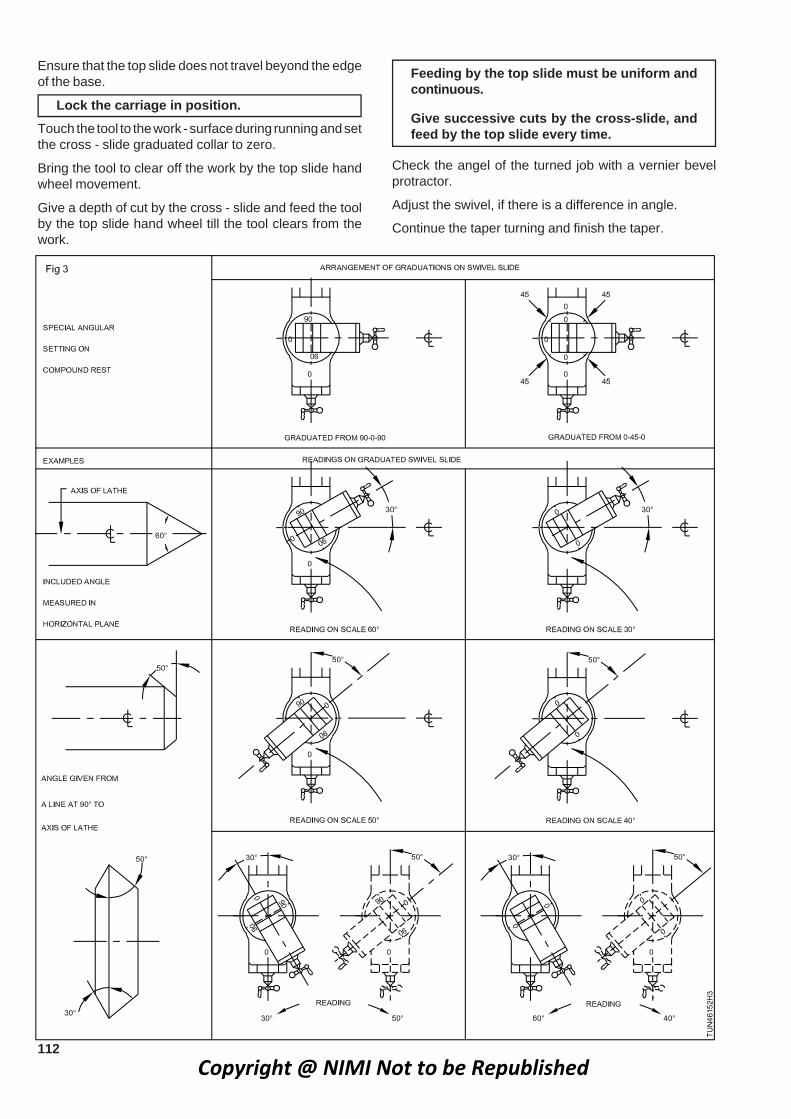
112
Ensure that the top slide does not travel beyond the edgeof the base.
Lock the carriage in position.Touch the tool to the work - surface during running and setthe cross - slide graduated collar to zero.
Bring the tool to clear off the work by the top slide handwheel movement.
Give a depth of cut by the cross - slide and feed the toolby the top slide hand wheel till the tool clears from thework.
Feeding by the top slide must be uniform andcontinuous.
Give successive cuts by the cross-slide, andfeed by the top slide every time.
Check the angel of the turned job with a vernier bevelprotractor.
Adjust the swivel, if there is a difference in angle.
Continue the taper turning and finish the taper.
Copyright @ NIMI Not to be Republished
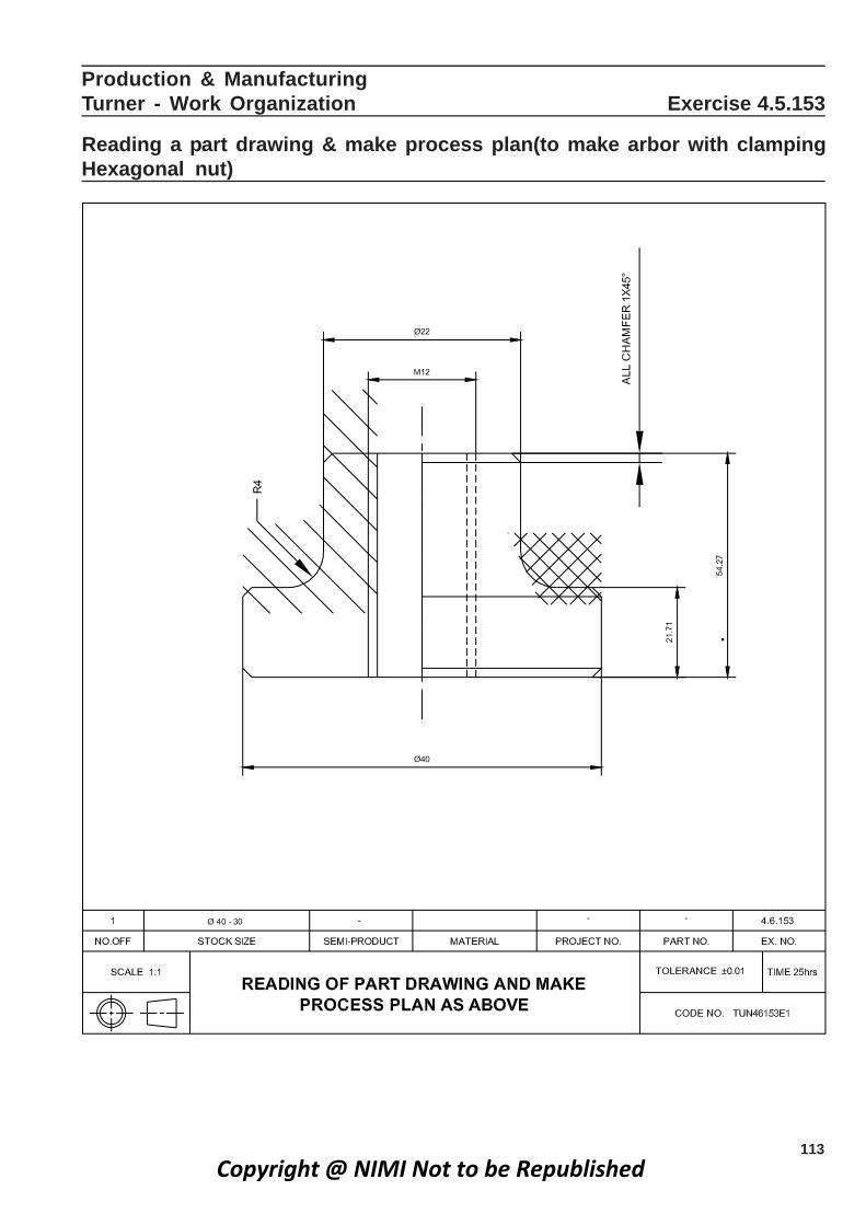
113
Production & Manufacturing noitazinagrO kroW - renruT Exercise 4.5.153
Reading a part drawing & make process plan(to make arbor with clampingHexagonal nut)
Copyright @ NIMI Not to be Republished

114
Par
t No.
Desc
riptio
n
Wor
king
ste
psLi
st o
f too
ls, e
qupt
s.
Mac
hini
ng p
aram
eter
s
F
orm
ula
Est
imat
ed
T
ime
o
f par
t
(Job
seq
uenc
e)
M
easu
ring
& M
arki
ng
C
uttin
g R
.P.M
.
Fee
d
Coo
lant
used
tim
e
take
n to
ols
Form
a ra
dius
of 4
mm
4 m
m ra
dius
tool
3030
0ha
ndSo
lubl
e-
10 m
inw
ith a
radi
us fo
rm to
ol15
0 m
m ve
rnie
r cal
iper
,fe
edoi
lan
d m
aint
ain
step
radi
us g
auge
leng
th 1
5 m
m
Pilo
t dril
l ∅5
mm
and
∅5
mm
dril
l ∅10
.25
mm
3570
0ha
ndSo
lubl
e-
10 m
indr
ill ∅
10.2
5 m
mdr
ill, H
SS
cham
ferin
gfe
edoi
lth
roug
h an
d ch
amfe
rto
ol
Cut
inte
rnal
thre
adM
12 ta
p, ta
p ho
lder
,20
300
mob
ile-
20 m
inM
12 b
y us
ing
a M
12th
read
plu
g ga
uge
oil
mac
hine
tap
Form
cha
mfe
r 1 x
45º
HS
S ch
amfe
ring
tool
3050
0ha
ndso
lubl
e10
min
on th
e ed
ge o
f ste
pfe
edoi
l∅
22 m
m
Rev
erse
and
hol
d th
ech
uck
key,
sur
face
10 m
inw
ork
on ∅
22 m
m a
ndga
uge
true
the
dia
and
face
Copyright @ NIMI Not to be Republished

115
Par
t No.
Desc
riptio
n
Wor
king
ste
psLi
st o
f too
ls, e
qupt
s.
Mac
hini
ng p
aram
eter
s
F
orm
ula
Est
imat
ed
T
ime
o
f par
t
(Job
seq
uenc
e)
M
easu
ring
& M
arki
ng
C
uttin
g R
.P.M
.
Fee
d
Coo
lant
used
tim
e
take
n to
ols
Rem
ove
mat
eria
l by
Faci
ng to
ol, 1
50 m
m30
500
0.
1 m
m/
solu
ble
10 m
infa
cing
and
mai
ntai
nve
rnie
r cal
iper
rev
oil
tota
l len
gth
25 m
m
Turn
39.
7 m
mH
SS
RH
turn
ing
tool
,35
500
0.
2 m
m/
mob
ile20
min
rem
aini
ng le
ngth
&15
0 m
m ve
rnie
r cal
iper
,re
voi
lsu
ppor
t with
the
revo
lvin
g cen
tre.
revo
lvin
g cen
tre.
Cha
mfe
r the
knur
led
HSS
dou
ble
side
3540
0ha
ndso
lubl
e15
min
surfa
ce 1
x 4
5ºch
amfe
ring
tool
feed
oil
Copyright @ NIMI Not to be Republished

116
Production & Manufacturing gninruT decnavdA - renruT Exercise 4.6.154
Practice of special operation on a lathe / Worm gear cuttingObjectives: At the end of this exercise you shall be able to• grind the under cut tool• grind the worm thread cutting tool• cut worm thread as required.
Copyright @ NIMI Not to be Republished

117
Job sequence• Check the raw material size.
• Hold the job in the 4 jaw chuck and true it.
• Face the one end.
• Centre drill the work.
• Turn ∅39.5 for the maximum length.
• Turn the step to dia 30mm x 43mm length.
• Turn the step to dia 25mm x 11 mm length.
• Undercut and maintain ∅21 and grooving width of 2 mmwith grooving tool.
• Reverse and hold the job in the chuck and true it.
• Face the other end to maintain 128 mm length.
• Centre drill the work.
• Turn ∅30 x 45 mm length.
• Turn step ∅27 x 25 mm length.
• Chamber the end 2 x 45º.
• Undercut from face end after 5 mm maintain ∅23 x2width.
• Undercut from face end after 23 mm to maintain grrove∅23 x 2 mm width.
• Undercut from face end after 38 mm.
• Undercut from face end after 35 mm to maintain groove∅26 mm x 2 mm width.
• Loosen and remove the job from 4 jaw chuck.
• Set the live centre and dead centre.
• Hold the job between centres.
• Finish turn ∅39 mm x 40 mm length.
• Set the included angle 29º thread tool.
• Cut the worm thread to a depth 4.5 mm.
• Remove burrs.
Production & Manufacturing : Turner (NSQF Level - 5) - Exercise 4.6.154Copyright @ NIMI Not to be Republished

118
Production & ManufacturingTurner - Advanced 551.6.4 esicrexEgninruT
Boring on the lathe using soft jaws to make bush with Standard collar)Objectives: At the end of this exercise you shall be able to• set the job in soft jaw• drill and enlarge it• make chamfer on the ends• bore the workpiece to the require size using soft jaws.
Copyright @ NIMI Not to be Republished

119
Job sequence
• Check the raw material for its size.
• Hold job in 4 jaw chuck about 15 mm outside and trueit.
• Finish face end and turn ∅75 mm x 15 mm length.
• Centre drill the work.
• Drill ∅10 mm, ∅16 mm, ∅25 mm through hole.
• Bore through hole to ∅48 mm (premachining).
• Chamfer one end 1 x 45°.
• Reverse the job and true it.
• Face the other end maintain length 10 mm
• Chamfer outer diametor by 1x45°.
• Loosen and remove the job from chuck.
• Hold the job in soft jaws.
• Set the boring tool correct centre height
• Bore the job to ∅50 mm.
• Check the bore size useing bore dial gauge.
Preparation of soft jaws discussed in 3rd sempractical Ex. No : 3.2.06
Production & Manufacturing : Turner (NSQF Level - 5) - Exercise 4.6.155Copyright @ NIMI Not to be Republished

120
Production & ManufacturingTurner - Advanced 651.6.4 esicrexEgninruT
Make a Arbor Support bush ( Proof machining)Objectives: At the end of this exercise you shall be able to• finish the bore within close limits• select the internal grooving tool• chamfer the edge and make an arbor bush.
Copyright @ NIMI Not to be Republished

121
Job Sequence• Hold the job in four jaw chuck and true it.
• Face the one end.
• Turn dia 60.05mm for the maximum possible length.
• Chamfer the end 2x45°
• Reverse the job and reset it.
• Face the other end and maintain to 100mm length.
• Turn to φ 60.00mm and complete the plain turningoperation.
• Chamfer the end 2x45°
• Centre drill the job
• Drill the job with a pilot drill φ 12mm
• Drill the job with a φ 20mm drill bit.
• Bore the drilled hole to φ 24.75 mm and chamfer1x45°.
• Ream the job with a φ 25 H7 machine reamer.
• Check the dimensions after deburing.
Production & Manufacturing : Turner (NSQF Level - 5) - Exercise 4.6.156
Copyright @ NIMI Not to be Republished