tutorial torque 04
DESCRIPTION
air gap torque under short circuitTRANSCRIPT

Copyrightcopy 2013 by Turbomachinery Laboratory Texas AampM Engineering Experiment Station
ELECTRIC MOTORS AND DRIVES IN TORSIONAL VIBRATION ANALYSIS AND DESIGN
Timo P HolopainenSenior RampD Engineer
ABB Motors and GeneratorsHelsinki Finland
Pieder JoumlrgSenior Drives Expert
ABB Drives and ControlsZuumlrich Area Switzerland
Jouko NiiranenCorporate Executive Engineer
ABB Drives and ControlsHelsinki Finland
Davide AndreoProduct Manager
ABB MiningDaumlttwil Switzerland
Timo Holopainen received his MSc de-gree in 1987 from Helsinki University ofTechnology Mechanical Engineering Hebegan his career at VTT ManufacturingTechnology working with strength andvibration control of marine structuresLater he focused on vibrations of rotatingmachines and received his Dr Tech de-gree from Helsinki University of Technol-
ogy Electrical Engineering Currently he works with rotor-dynamics and vibration control of large electric motors at ABBMotors and Generators Technology Development He is amember of API 684 Task Force (Rotordynamic Tutorial) andIFToMM Technical Committee for Rotordynamics
Jouko Niiranen received his MSc degree in1980 and Dr Tech degree in 1990 bothfrom Helsinki University of TechnologyFinland (now Aalto University) Niiranenstarted with Stromberg (later ABB) tractiondrives in 1981 During 1989-1993 he wasas a researcher with the Power Electronicsand Electric Drives Laboratory of HelsinkiUniversity of Technology Since 1993 he
has worked with ABB in various research positions dealingwith torsional vibration damping converter control simula-tions and wind turbine drives Niiranen has also been a docentat Aalto University School of Electrical Engineering Finlandsince 1994
Pieder Joumlrg received his MSc degree 1995from the Swiss Federal Institute of Tech-nology Zurich He joined ABB at Corpo-rate Research in the area of power elec-tronics In 2002 he joined the business unitMedium Voltage Drives as head of productdevelopment Since 2010 he is focusing onbusiness and technology development fordemanding drives applications He has
been involved in various studies and improvement projects in-volving large VSD driven systems with demanding rotor dy-namics
Davide Andreo is currently Product Man-ager for Drive Systems at ABB Mining inDaumlttwil Switzerland Previously to that heworked as RampD Engineer at ABB MediumVoltage Drives in Turgi Switzerlandwhere he focused on electrical drive sys-tems design and motor control softwarefor applications including Oil amp Gas Hereceived his MSc degree in Mechatronics
Engineering in 2008 from the Politecnico di Torino Italy
ABSTRACT
Two types of prime movers are continuously applied forrotating machinery mechanical and electric drives This tutori-al focuses on electric drives which are actually composed ofseparate components electric motor frequency converter (op-tional) and electric network including transformers The main aim of this tutorial is to explain the phenomenaof electric drives related to the torsional vibrations All thecomponents of an electric drive may affect torsional dynamicsof the system Naturally the main concern is torsional excita-tions Another aspect is the electromechanical interaction in theair-gap of the motor that produces electromagnetic torsionalstiffness and damping These and other similar phenomenarelated to the electric drives have been observed on test fieldsand site conditions The scope of the paper includes the mostcommon induction synchronous and permanent magnet mo-tors First the various rotor structures of electric motors arediscussed Then the effects of electromagnetic stiffness anddamping on the torsional dynamics are introduced Next themain electric excitations are presented and their effect on drive-train dimensioning is discussed Various modelling and analy-sis methods are also presented for drive-trains with an electricmotor The previous sections focus on the motor without any fre-quency converter The rest of the paper deals with the variablespeed drives First the main voltage source inverter currentsource inverter and load commutated inverter drive types theiroperational principles and application areas are introducedThen the harmonic and inter-harmonic torsional excitations are
Proceedings of the Forty-Second Turbomachinery SymposiumOctober 1-3 2013 Houston Texas
Copyrightcopy 2013 by Turbomachinery Laboratory Texas AampM Engineering Experiment Station
explained that depend on the configuration and control of thefrequency converter The main functionality of a variable speed drive system isthe speed-control feedback loop This loop is used to maintainthe preset speed Although this feedback loop is also a potentialsource of instability it can with proper tuning be used to damplow frequency torsional resonances The analysis guidelines and design principles are distribut-ed throughout the paper The paper is concluded with summaryand main recommendations
INTRODUCTION
The electrical drives are composed of an electric motor andits electric supply system Thus analysis cannot always be lim-ited to the electric drives but have to be extended over thewhole electric drive from the shaft-end to the electric grid in-cluding the optional frequency converter
In order to predict the vibration behaviour of any torsionalsystem the inertia and stiffness characteristics of all the com-ponents are needed Typically the electromagnetic stiffness anddamping due to the electromechanical interaction in the air-gapare ignored but they can be important when improved predic-tion accuracy of natural frequencies or damping is required Inaddition to dimension the drive-train components all the exci-tations must be known both in the rated operation conditionsand during the different failure occurrences
In most industrial cases the drive train components are de-signed and manufactured by various vendors Usually thesevendors are well familiar with their own component but onlysuperficially acquainted with other components This poses achallenge to the system integrator to successfully design hissystem The main aim of this tutorial is to explain the phenomenaof electric drives related to the torsional vibrations with a tar-get audience of mechanical engineers with background in tor-sional dynamics but without previous knowledge of electricalmachines The scope of this paper will be the modelling analy-sis and design of electrical drives as a part of torsional systems
COMPONENTS AND TYPES OF ELECTRIC DRIVES
The function of electric drives is to convert electric energyinto the form of mechanical energy The electric energy is sup-plied by the electric grid and the mechanical energy appears asa rotating shaft end The main parameters describing the elec-tric drives are power and speed The basic principles of electricdrives and power conversion are presented eg by Fitzgeraldet al (2003) and Barnes (2003)
Power Conversion
The power conversion is produced by the magnetic field inthe air gap between the rotor and stator The magnetic field ischaracterized by the number of poles The number of poles isdefined by the motor construction Because every north pole ofa magnet has to have a corresponding south pole the number ofpoles is always even Figure 1 shows a cross-section of theelectromagnetically active parts of a small electric motor Themain structural parts of an induction motor are shown in Fig 2
Figure 1 Magnetic Field of a Four-Pole 15 kW Induction Mo-tor (Holopainen and Arkkio 2008)
Stator core
Stator windingAir-gap
Rotor bar
Rotor core
Shaft
Stator core
Stator windingAir-gap
Rotor bar
Rotor core
Shaft
Figure 2 Main Parts in the Core Region of a Four-Pole 15 kWInduction Motor (Holopainen amp Arkkio 2008)
Motor Speed
Most of the industrial motors are supplied by alternatingcurrent (AC) There are also direct current (DC) motors butthey are omitted in this paper Two main types of AC motorsexist synchronous and asynchronous Asynchronous motorsare also called induction motors The rotor of a synchronousmotor rotates synchronously ie with the same angular speedof the magnetic field The relation between the synchronousspeed 1n and the motor supply frequency given in revolutionsper minute (rpm) is
Hzrpm60 1
1 pfn times
= (1)
where 1f is the supply frequency in Hz and p is the number ofpole-pairs of the motor It can be seen that the number of poles(= p2 ) is closely related to the speed of the motor For exam-ple the speed of a four pole synchronous motor fed from 60 Hzgrid is 60 60 Hz 2 rpmHz = 1800 rpm
The rotor of an asynchronous motor rotates asynchronous-ly ie with a lower angular speed than the magnetic field Therelation between the rotor speed and the motor supply frequen-cy of an asynchronous motor in rpm is
Copyrightcopy 2013 by Turbomachinery Laboratory Texas AampM Engineering Experiment Station
( )Hzrpm160 1
pfsn times-times= (2)
where s is the slip The slip is the relative speed differencebetween the magnetic field and rotor angular speed
1
1
n ns
n-
= (3)
where 1n is the synchronous rotational speed in rpm The typi-cal order of magnitude of the slip is 001 - 1 percent in the ratedoperation condition Thus the load only slightly affects thespeed of induction motors
Adjustment of Speed
As shown above the rotational speed of direct-on-line(DOL) motors is quite fixed Stepwise speed control is possiblewith special pole-changing induction motors that have morethan one set of windings in their stator With a 60 Hz grid therpm alternatives for synchronous speeds are 3600 1800 1200900 etc Pole-changing motors usually have two or three con-secutive speeds from the previous list as their synchronousspeeds Due to the fairly obvious advantages of stepless speed con-trol the application of frequency converters has increased re-markably during the last twenty years The main task of thefrequency converter is to adjust the frequency of the voltage fedto the motor in order to achieve the needed rotational speed ortorque This can be achieved with various control schemes withor without speed feedback
Electric Grid
The last component of an electric drive is the electric gridThere are remarkable variations in electric grids used to supplyelectric motors An essential feature of these distribution gridsis the stability The quality of power supply affects directly thetorsional dynamics of a drive-train including a DOL motor Theunbalance between the phases and short circuits are well-known examples of electrical network disturbances appearingas extra excitations As an additional benefit if a frequencyconverter is used most of these disturbances originated in thegrid are isolated from the torsional system
TORSIONAL STIFFNESS AND DAMPING OF ROTORSTRUCTURES
The rotor construction of an electric motor varies greatlydepending mainly on the motor type motor size and operation-al speed The different constructions balance the electromagnet-ic and mechanical requirements of various applications Theelectrical requirements are closely related to the total electriclosses and the mechanical requirements to the rotor strengthand thermal stability
Induction Motors
The typical features of an induction motors are the lami-
nated rotor core and the rotor cage (Figure 1) The lamination ismade of electrical steel sheets with thickness for example 05mm The typical materials of the cage are copper aluminumand bronze In addition the rotor core of large motors usuallyincludes axial and radial air ducts for the cooling purposes
Synchronous Motors
The rotor design of large synchronous motors is always abalanced solution between the electrical cooling and mechani-cal performance In low speed motors the mechanical require-ments are smaller and the electrical optimization leads to a sali-ent-pole rotor design with poles made of laminations of steelThe armature and damper winding together with additionalcooling ribs are mounted around the poles These poles are usu-ally removable and mounted separately on the rotor shaft With increasing speeds the mechanical requirements areemphasized A common solution is to apply a salient-pole de-sign with a solid steel shaft with poles In this design the re-movable armature windings are restrained by pole shoes Thisdesign with four poles is used for applications exceeding 2000rpm The design of non-salient pole rotors with solid core is de-termined strongly by mechanical requirements These usuallytwo-pole rotors are used for even higher speed applicationsexceeding 6000 rpm The core is made of solid steel withmilled slots for armature windings The synchronous motors with permanent magnet technolo-gy rely on magnets fitted in or on the rotor The rotor core isusually made of steel laminations
Rotor Inertia and Stiffness
A proper torsional analysis and design of a drive-train re-quires that there is adequate data describing the stiffness andinertia characteristics of the rotor A common industrial prac-tice is based on the rotor drawing with complementary datafrom motor manufacturer In practice all the rotor constructions are fabricated struc-tures consisting of possibly hundreds of separate parts Theseparts are fitted together by different connection methods likedovetail joints bolted joints friction joints interference fitswedging etc In addition some of the fabricated rotors are resintreated which affects the joints of the structure Finally due tothe different thermal expansion factors of steel and windingmaterials like copper the connection between the parts maychange as a function of rotor temperature The distribution of rotor inertia is usually relatively well-known and can be easily used in the rotordynamic analysesThe determination of the torsional stiffness characteristics ismore problematic The easy part is to calculate the torsionalstiffness of the solid part of the rotor without any joints Forcylindrical sections there is a well-known simple formula forthe torsional stiffness
4π32GDk
L= (4)
where G is the shear modulus D is the diameter and L is thelength of the section When the cross-section of a solid shaft is
Copyrightcopy 2013 by Turbomachinery Laboratory Texas AampM Engineering Experiment Station
non-cylindrical analytical formulas can be applied (Wilson1956 API 684) A typical example of these is a spider shaft Inaddition the finite element method can be used for more com-plicated cross-section geometries and for the modeling of ab-rupt shaft changes in axial direction This means that the stiff-ness of the solid shaft part of the rotor can be estimated withdesired accuracy The most challenging aspect is to determinethe stiffening effect of the rotor core
Stiffening Effect of Rotor Core
The stiffening effect depends on the rotor core construc-tion For example the stiffening effect of a laminated core withradial air-ducts without resin treatment is naturally small Thestiffening effect can be estimated by different calculation meth-ods An essential observation is that the laminated rotor core istransversely isotropic and defined by the five independent elas-tic properties (Pilkey 1994) The material properties in trans-versal direction are close to those of steel In axial direction themodulus of elasticity is much lower Garvey et al (2004) re-ported typical values for the modulus of elasticity in axial di-rection Ea = 120000 ndash 260000 lbfin2 (08 ndash 18 GNm2) Thepotential radial air-ducts reduce this equivalent axial value evenmore Further the axial modulus of elasticity can be used toestimate the effective shear modulus that is required when thestiffening effect is evaluated The published information about stiffening effect is fo-cused mainly on lateral rotordynamics (Garvey et al 2004)They present an approach to model the stiffening effect of lam-inated rotor core and a method to determine the required pa-rameters from experimental results This approach can be ap-plied for the parameter estimation of stiffening effect in tor-sional vibrations A common approach is to measure the naturalfrequencies of a free-free rotor and adjust the physical parame-ters to predict as many lowest modes as possible
Mechanical Damping
Considering that the rotor of an electric motor is fabricatedand there are usually plenty of friction joints it is a bit surpris-ing that the mechanical damping is usually low This observa-tion is consistent with the experience of drive-train dampingThe typical damping ratio of a gearless drive train is about 1percent (Corbo and Malanoski 1996) The typical drive-trainsinclude electric motors and thus these values can be applied forthe mechanical damping of their rotors
Analysis Guidelines
The modeling of the solid steel part and the inertia of therotor is relatively straightforward It is good to remember thatthe torsional stiffness is proportional to the fourth power of theshaft diameter Thus the shaft sections close to the couplingand the drive-end journal are most flexible and dominate themotor contribution to the coupling mode (= nodal point of themode roughly in the coupling) Anyway the pivotal componentdominating the coupling mode frequency is usually the cou-pling The stiffening effect of the rotor core varies depending onthe core structure Motor manufacturers may have experimental
values for stiffening effect of different core structures Thesevalues if available may improve particularly the prediction ofhigher frequency modes In these modes the torsional defor-mation occurs along the core region While the rotor is a fabricated structure with multitude ofparts a damping ratio applied for general torsional systems eg1 percent is a good choice for rotors of electric motors
NATURAL MODES AND FREQUENCIES
The torsional modes and frequencies of an electric motorrotor are determined by the distribution of stiffness and inertiaTypically the main part of the inertia is roughly evenly distrib-uted in the rotor core In some synchronous machines there isanother remarkable inertia in the form of an exciter A charac-teristic parameter related to the torsional behavior is the relativediameter of the rotor core compared to the core length In gen-eral the relative diameter is smaller with rotors for higher rota-tional speeds As an example Figure 3 shows the five lowest torsionalmodes and frequencies of a two-pole 9400 hp (7 MW) induc-tion motor The relative rotor diameter is 046 and the rotor isrigidly fixed in the coupling end
Rotor core
Figure 3 The Five Lowest Torsional Modes of a Two-Pole9400 hp Induction Motor with Rigidly Fixed Coupling End onthe Left High up the Geometry of the Shaft without RotorCore is Shown
Copyrightcopy 2013 by Turbomachinery Laboratory Texas AampM Engineering Experiment Station
ELECTROMECHANICAL INTERACTION
Even Distribution of Torque
The electromagnetic field in the air-gap of an electric ma-chine produces electromagnetic forces between the rotor andstator These electromagnetic forces on the surface of the rotorcan be divided between the radial and tangential componentsOnly the tangential component in circumferential direction ieelectromagnetic traction is relevant on the torsional behaviorThe distribution of this electromagnetic traction has useful reg-ular features Particularly if we consider any arbitrary timeinstant the amplitude of electromagnetic traction is practicallyconstant as a function of axial coordinate and varies cyclicallyin the circumferential direction This means that the distributedtraction on the surface of the rotor generates an electromagnetictorque which is evenly distributed over the length of the coreThese general statements about a) the prismatic distribution oftraction and b) the even distribution of torque are true for thedistributed load and separately for each harmonic componentThus the torque distribution of a) the fundamental field b) theharmonic components and c) the inter-harmonic componentsare evenly distributed over the rotor core In addition the dis-tributed torque of each component has a common phase overthe rotor core There is one exception for the prismatic distribution oftraction In some motors the rotor or stator slots are skewed inorder to reduce the harmonic components of electrical torque
Modal Sensitivity Factor
The evenly distributed torque over the length of the coretogether with the variation of modal amplitudes determines theeffective torque of each mode The effective modal torque canbe calculated by integrating the product of the evenly distribut-ed torque and the mode shape over the rotor core The compari-
1E-08
1E-07
1E-06
1E-05
1E-04
1E-03
1E-02
1E-01
1E+00
1 2 3 4 5 6 7 8 9 10
fixed even
free even
fixed max amp
Mode No
Rela
tive
mod
een
ergy
Figure 4 Relative Mode Energy in Resonance Condition Excit-ed by an Evenly Distributed Unit Torque or by a Unit Torque inMaximum Modal Amplitude of the Core
son of modal excitation sensitivity for electromagnetic torque ismore difficult One measure to evaluate this modal sensitivity isto calculate the kinetic or strain energy in the resonance condi-tion Figure 4 shows the relative strainkinetic energy for theunit harmonic excitation torque with a modal damping factor (2percent) The example rotor is the same two-pole 9400 hp rotorpresented above The effect of boundary condition is evaluatedby applying fixed (=rotation restricted) or free connection (=rotation totally free) in the coupling end It is assumed thatthese two extreme conditions give qualitatively the overall pic-ture of the behavior with real torsional trains The natural fre-quencies of these modes with fixed boundary condition arebetween 49 Hz and 2031 Hz The five lowest modes are shownin Figure 3 The natural frequencies with free boundary condi-tion are between 0 Hz and 1864 Hz The zero frequency mode(No 1) is the rigid body mode and the first elastic mode has thefrequency 269 Hz Finally Figure 4 shows also the relativestrainkinetic energy in the resonance with fixed boundary con-dition and excited by a unit torque in the maximum modal am-plitude of the core region Figure 4 shows clearly that the evenly distributed torque(in the same phase) will be effectively cancelled out by the spa-tial variation of the second and higher modes The effect ofboundary conditions in the coupling end seems to be minor The cancelling effect due to torque distribution cannot bepresent when the torque is given in one point on the core Thusthe decreasing curve of the unit torque response in Figure 4means that the relative mode energy decreases with increasingmode number The additional decrease between the unit torqueand evenly distributed torque response shows clearly the can-celling effect of the mode shapes It can be added that the rotorstresses determining the dimensions are proportional to thesquare root of the strain energy The example rotor used in the example calculations wasslender with relative rotor core diameter 046 The situationchanges slightly when the rotor core is shorter or it is unsym-metrically located on the shaft However it can be concludedthat in general only the lowest mode ie the coupling modecan be effectively excited by the electromagnetic torque In addition if there are other drive-train modes with motorcore oscillating without twisting these modes are prone to elec-tromagnetic excitations One example is the vibration mode ofa synchronous motor with twisting between the motor core andexciter Usually the excitation of higher modes with naturalfrequency clearly above the coupling mode is effectively can-celled out
Analysis and Design Guidelines
The most prone mode for the electrical excitations is thelowest mode ie the coupling mode In addition the electro-magnetic excitation may excite drive-train modes with motorcore oscillating without significant twisting The higher modeswith motor core twisting cannot be excited easily by electricalexcitations Among other things this means that the high-orderharmonics (6th 12th hellip) of frequency converters are effectivelycancelled out by electric motors In order to model the high-frequency behavior reliably it is
Copyrightcopy 2013 by Turbomachinery Laboratory Texas AampM Engineering Experiment Station
essential to use a refined model ie short elements for the ro-tor core and apply evenly distributed torque to describe theelectromagnetic excitations These modeling principles are nec-essary to model the cancelling effect of high-frequency modes
ELECTROMAGNETIC STIFFNESS AND DAMPING
Electromechanical Interaction
The electro-mechanical conversion of power is producedby the constant component of air-gap torque The time-harmonic components of the torque are torsional excitationsThese electromagnetic excitations will be considered in thenext section In addition to the valuable torque production andthe harmful excitations there is a third phenomenon related tothe time-variation of the electromagnetic torque The source ofthis phenomenon is the interaction of the rotor oscillation andthe electromagnetic fields Due to this interaction an oscillatingmotion produces always a corresponding harmonic torque withthe same frequency This interaction turns up as an electromag-netic stiffness and damping coefficients These resemble thenegative stiffness and damping coefficients applied in lateralrotordynamics of electrical machines but are somewhat differ-ent
Example of Stiffness and Damping
Figure 5 shows as an example the calculated electromag-netic stiffness and damping of an eight-pole 1250 hp (932 kW)induction motor for blower application The motor operates insteady-state condition with the supply frequency of 60 Hz andthe stiffness and damping is determined for the oscillating mo-tion as function of its frequency Figure 5 shows that the electromagnetic stiffness is rela-tively constant over the frequency range The drop the stiffnessis related to the supply frequency of 60 Hz The electromagnet-ic damping varies strongly The most significant is the range ofnegative damping between 497 -594 Hz This range is locatedsomewhat below the supply frequency The damping coeffi-cient approaches the value 10600 Nmsrad when the frequency
-100
0
100
200
300
400
500
0 20 40 60 80 100
Frequency [Hz]
Stif
fnes
s[k
Nm
rad]
Dam
ping
[Nm
sra
d]
StiffnessDamping
Figure 5 Torsional Stiffness and Damping of a 1250 hp Induc-tion Motor with Supply Frequency 60 Hz (Holopainen et al2010)
approaches zero This damping value at zero frequency is equi-valent with the derivative of the speed-torque curve in the ratedoperation point It can be concluded that the electromagneticdamping is strongly dependent on the oscillation frequency
Significance of Electromechanical Interaction
The significance of electromagnetic stiffness and dampingis dependent on the application The presented 1250 hp motorwas used to drive a blower in a direct-on-line application(Holopainen et al 2010) This drive-train is basically a two-inertia system with the lowest natural frequency at 281 Hzwithout electromechanical interaction In the rated operationcondition the supply frequency is 60 Hz and the rotationalfrequency 149 Hz ie 892 rpm
The electromagnetic interaction increased the torsionalnatural frequency 43 percent up to 294 Hz and the purelyelectromagnetic damping ratio was 06 percent In addition theoriginally rigid body mode at 0 Hz appears in the ratedoperating condition at 51 Hz The damping ratio of this modeis 23 percent This natural frequency and mode remains usuallyunnoticed because the electromagnetic damping is so large
It can be concluded that the significance of electromagneticeffects is dependent on the mode shape and particularly thevibration amplitude of the rotor core The inertia ratio ie themotor inertia divided by the load inertia of the examplemachine is relatively small 057 This leads to large relativeamplitude of the rotor core and further to more significanteffects of electromechanical interaction
Other Machines
The electromagnetic stiffness and damping presented inFigure 5 is qualitatively representative for induction machinesThe general shape of the curves follows from the physical prin-ciples of induction motors Thus the presented behavior is in-herent for all induction motors Thus it can be assumed that theelectromagnetic stiffness is always positive and that the damp-ing has a negative value in a frequency range just below thesupply frequency Figure 6 shows electromagnetic stiffness and damping of a36000 hp (27 MW) salient-pole synchronous motor for pistoncompressor application The supply frequency is 50 Hz and therotational speed 200 rpm As can be seen by comparing Figures5 and 6 the behavior is qualitatively very similar There is onlyone exception the electromagnetic stiffness at zero frequencyis larger than zero 276 MNmrad The frequency of originallyrigid body mode increases up to 27 Hz and the damping ratioup to 140 percent due to electromagnetic interaction It can bementioned that this mode is sometimes critical because the pis-ton excitations are relatively large and may coincide with thismode The behavior of permanent magnet motors is different Therotor construction of these motors does not include windingsWithout windings there will not be any anomaly in stiffnessand damping values close to the supply frequency and thus thefrequency dependency is small In addition the electromagneticdamping is small compared to induction and other synchronousmotors
Copyrightcopy 2013 by Turbomachinery Laboratory Texas AampM Engineering Experiment Station
-100
0
100
200
300
0 20 40 60 80 100
Frequency [Hz]
Stif
fnes
s[M
Nm
rad]
Dam
ping
[kN
ms
rad]
StiffnessDamping
Figure 6 Torsional Stiffness and Damping of a 36000 hp Syn-chronous Motor with Supply Frequency 50 Hz (Holopainen etal 2010)
Design and Analysis Guidelines
The electromagnetic stiffness and damping affects the tor-sional dynamics of the system Currently the inclusion of theseeffects is not common The reason for this is most probably themissing interface between the rotordynamics and electromag-netic calculations It is clear that the effect of electromagnetic interaction islargest in the coupling mode and particularly in applicationswere the load inertia is large compared to the motor inertia Inaddition it is known and can be cautiously used that the elec-tromagnetic stiffness may increase the natural frequency of thecoupling mode by some percent The electromagnetic damping can be regarded mainly as anadditional bonus for the mechanical damping of the systemHowever it is good to be aware of the negative damping ratiobelow the supply frequency In our induction motor examplethe negative damping ratio frequency was 83hellip99 percent andin the synchronous motor example 92hellip100 percent of the sup-ply frequency The contribution of negative damping could be aproblem if there is a torsional mode close to the supply fre-quency However there are recommendations and in somestandards requirements that all the natural frequencies of acomplete train must be removed at least 15 percent (API 541Induction motors) or 10 percent (API 546 Synchronous motors)from the line frequency
ELECTROMAGNETIC AIR-GAP LOADS
Steady State Operation
The electromagnetic excitations of an ideal electric motorin steady state operation are usually very small The potentialexcitations occur at high frequencies due to slot harmonics Themeaning of these harmonics is usually minor in the design ofthe torsional drive-train If the voltage supply is unsymmetrical there will be anexcitation torque at twice-line frequency In principle a rotor
eccentricity may also appear as a twice-line excitation sourceTheoretically there is not any excitation at line frequency for athree phase motor and it is difficult to find any non-ideality togenerate this component However there seems to be empiricalobservations that indicate the existence of line frequency exci-tations It has been suggested representative torque magnitudesof 10 percent of rated torque for the line frequency excitationsand 05 percent for the twice-line frequency excitations (Wa-chel and Szenasi 1993 Corbo and Malanoski 1996 API 684)
Starting
The direct-on-line start of an electric motor generates hightransient torque fluctuations at line-frequency The length ofthis air-gap transient is usually a fraction of a second The max-imum torque amplitude is dependent on the motor characteris-tics but the typical values are 4-7 times the rated torque The direct-on-line start of a synchronous motor has an ad-ditional excitation component which must be considered partic-ularly with large motors This torsional excitation occurs at twotimes the slip frequency when the motor operates in the asyn-chronous starting mode The frequency of this excitation can begiven by the formula
1exc 1
1
2n n
f fn-
= times (5)
This means that the excitation will be two times the line fre-quency at start and will reduce linearly with speed increasingtowards the operational speed Because the coupling mode is inpractice always below the twice-line frequency this loadingwill excite this resonance vibration Though this resonance willbe transient this loading is usually critical for the dimensioningof shaft systems of large synchronous DOL motors The start-ing of synchronous motors has been presented in API 684 (API684) and discussed thoroughly by Corbo et al (2002)
Electric Faults
A short-circuit is the most common electric fault affectingthe electric motor and thus the whole drive-train Two types ofthese failure cases are typically used for the dimensioning ofthe system three-phase and two-phase short-circuit Singlephase-to-ground faults are much rarer and less severe for themotor and are thus usually neglected The transient of the three-phase short-circuit is very similarthan the transient of the DOL start of the machine The fre-quency of this transient is the line-frequency and the typicalmaximum amplitude of the fluctuation 4-7 times the rated air-gap torque The two-phase short-circuit includes two frequencies theline and the twice-line components The maximum amplitude istypically 5 ndash 15 times the rated air-gap torque Figure 7 showsan example of a two-phase short-circuit torque It can be added that the short circuit torque amplitude isdependent on the location of a short circuit If the fault occursfar away in the supply network the short-circuit torque will beattenuated In principle the situation is worst when the shortcircuit occurs in the motor terminals This worst case scenariois usually applied in the calculations
Copyrightcopy 2013 by Turbomachinery Laboratory Texas AampM Engineering Experiment Station
Reclosure and Bus-transfer
The power supply of an electric motor can be interruptedby faults in the power system The reapplication of the power iscarried out by the breaker reclosure This may involve a bus-transfer where the power transmission supply line is changed Itis important that a premature reclosure of a motor may induce atransient which in induction motors can be as high as 15 ndash 20times the rated torque (API 684) The synchronous motors havesimilar behavior and the reclosure torques can be even higherThe reason for these torque transients is the residual magneticflux which remains in the motor after the voltage supply is in-terrupted The transient torque is generated by the interaction ofthis residual flux and the new current inrush due to the reclo-sure The induced torque transient is a function of the remain-ing residual flux and the phase difference between the residualflux and the flux generated by the inrush currents The remedyfor these transients is the adequate reclosure control (API 684NEMA MG-1 ANSI C5041)
-20
-15
-10
-5
0
5
10
15
000 005 010 015 020 025 030 035 040
Time [s]
PerU
nitT
orqu
e
Two-Phase Short Circuit Torque
Figure 7 A Typical Two-Phase Short-Circuit Torque in theAir-Gap of a Motor
Analysis and Design Guidelines
The steady-state excitations seem to be negligible from thetorsional dynamics point of view The most important excita-tion for the dimensioning of drive-train components is usuallythe two-phase short-circuit The maximum air-gap amplitude ofthis fault condition is typically 5-15 times the rated torque ofinduction and form-wound synchronous motors The maximumtorque of permanent magnet motors is remarkably lower typi-cally 2-3 times the rated torque The motor manufacturer pro-vides usually this maximum amplitude for each motor It is significant that the excitation frequencies of mainshort-circuit faults occur at one and two times the grid or sup-ply frequency ie 60 Hz and 120 Hz This means that the ad-verse effect of these transients can be avoided by adjusting thenatural frequencies far enough from these frequencies This willbe discussed in the next section One remarkable challenge is the DOL start of large syn-chronous motors Sometimes the design of drive-train compo-nents is based on the limited number of starts during the life-time of the motor A premature reclosure may generate a very strong transientair-gap torque The main frequency component of this torquedepends on several parameters and cannot be predicted easilyThus the risk for drive-train failure is large when a prematuretorque appears Thus the recommended approach is to apply anadequate reclosure control
SHAFT-END TORQUE
Electrical calculations provide the air-gap torque in steady-state operating starting and fault conditions Usually it is notreasonable to apply the air-gap torques directly to the dimen-sioning of the drive-train components and driven machine Amore refined dimensioning is based on the dynamics of thedrive-train system As an example we consider in this sectionthe dimensioning torques of the coupling
A Simple Two-Inertia System
We assume that the drive train can be simplified to a sim-ple two inertia system electric motor ndash coupling ndash driven ma-chine This system can be presented by the formula (Ehrich2004)
( )2
1 2 212 12 12
1 2 1 2
I I Id dB K T tI I dt I Idt
y yy+ + =
+ + (6)
where 1I and 2I are the mass moments of inertia for the motorand driven machine 12K is the torsional stiffness between theinertias 12B is the viscous damping coefficient y is the angleof twist in the connecting shaft and ( )1T t is the air-gap torqueThe amplitude of the shaft end torque 12T due to the harmonicair-gap torque ( )1 1 sinT t T tw= can be written in the form
( ) ( )2
12 1 2 221 2
1ˆ ˆ1 2
IT T
I I t zt= times times
+ - + (7)
where t is the frequency ratio between the exciting frequencydivided by the undamped natural frequency of the torsionalsystem and z is the damping ratio
Inertia Factor
Equation (7) shows that the shaft-end torque is obtainedfrom the harmonic air-gap torque by multiplying it with twoterms the inertia factor (= the load inertia divided by the totalinertia) and the dynamic amplification factor Figure 8 showsthe effect of the ratio I1I2 on the shaft-end torque It can beseen that the quasi-static shaft end torque is always lower thanthe air-gap torque For constant acceleration or deceleration ofthe drive the frequency ratio is zero and thus the inertia factorgives directly the amount of the shaft-end torque
Figure 8 Effect of Ratio I1I2 on the Inertia Factor
Copyrightcopy 2013 by Turbomachinery Laboratory Texas AampM Engineering Experiment Station
Dynamic Amplification Factor
Figure 9 shows the effect of the dynamic amplification factoron the shaft-end torque The excitation frequency is assumed tobe 60 Hz
0
1
2
3
4
5
0 20 40 60 80 100 120
z = 00
z = 002
z = 010
Figure 9 Dynamic Amplification Factor as Function of NaturalTorsional Frequency with 60 Hz Excitation Frequency
Figure 9 shows that the dynamic amplification factor has a re-markable effect on the shaft end torque Usually the torsionalnatural frequency is clearly lower than the supply frequencyThus the dynamic amplification is lower than one eg withtorsional natural frequency 20 Hz we get for the dynamic am-plification factor 0125 The effect of damping outside the reso-nance is minor Equation (7) gives the shaft-end amplitude for the harmon-ic excitation The amplitudes of harmonic excitations in ratedoperating condition are very small The recommended designvalues are typically 1 ndash 2 percent (API 684) and thus the shaftend torque oscillation will be very small assuming that the exci-tation does not coincide with the resonance frequency Usuallythe shaft-end torque due to electrical faults is more significantfor the dimensioning of the coupling and other drive-train com-ponents Next we consider the two-phase short-circuit as anexample of electric faults
Two-Phase Short-Circuit
A simplified form of a two-phase short-circuit can be givenby the formula (DIN 4024)
( ) ( ) ( )15001
4021
140
0sc e12sinesine10 ttt TttTtT --- ---= ww (8)
where 0T is the rated torque of the motor and 1w is the angulargrid or supply frequency This transient excitation can be usedto evaluate the dynamic amplification factor of two-phaseshort-circuit loads An updated version of Equation (7) includ-ing the effect of the transient excitation can be written in theform
( )( ) ( )222
sc
21
2sc1sc12
21
ˆˆztt
zt
+-times
+times= A
IIITT (9)
where ( )zt scA is the factor for the short-circuit loading Fig-ure 10 shows this term multiplied by the dynamic amplificationfactor as a function of torsional natural frequency for a 60 Hzsupply
0
1
2
3
4
5
0 20 40 60 80 100 120 140
z = 00
z = 002
z = 010
Figure 10 Amplification Factor for Transient Short-CircuitLoad (DIN 4024) as Function of Torsional Frequency of theLowest Mode with 60 Hz Grid Frequency
By comparing Figures 9 and 10 we can observe that the ampli-fication factor of the transient excitation is lower than that ofthe harmonic excitation up to about 100 Hz When the naturalfrequency of the torsional system is higher than 100 Hz thetwice-line component excites this natural frequency Figure 10shows clearly that when the natural frequency is clearly lowerthan the supply or grid frequency the amplification factor isless than one
Other Loads and General Drive-Trains
The simple calculation example above was based on thetwo-inertia model of the drive train and only the harmonic andshort-circuit excitations were studied However this simpleexample is representative for general drive-train systems Firsta two-inertia model with a torsional spring can be extractedfrom a general drive-train system The motor inertia is in prac-tice without exceptions one of these two inertias Thus thetwo-inertia model represents adequately the lowest torsionalmode Second the fault conditions and starting are the mainexcitation sources All of these loads are transient by natureThese transient loads occur at line and twice-line frequencyThus the lowest excitation frequency occurs at supply frequen-cy Third the inertia ratio presented in Figure 8 is determinedtypically by the application and drive-train arrangement Thusthe inertia ratio may only decrease the shaft-end torque Fourthand finally the transmission of all these transient excitationscan be eliminated by designing the lowest natural mode clearlybelow the grid or supply frequency The amplification factor isless than one when the frequency ratio is about 075 ie thenatural frequency is 45 Hz with 60 Hz supply frequency
Copyrightcopy 2013 by Turbomachinery Laboratory Texas AampM Engineering Experiment Station
It must be added two exceptions for the main excitationfrequencies The starting of salient-pole synchronous motorsexcites all the frequencies between zero and twice-line frequen-cy and the premature breaker reclosure may generate low fre-quency excitations The first one is unavoidable but the vibra-tion amplitude can be attenuated by accelerating (or decelerat-ing) the system as quickly as possible over the resonance fre-quency The best way to handle the premature breaker reclosureproblems is to resort to adequate reclosure control methods
Analysis and Design Guidelines
The air-gap torque is determined by the electric system andthe transient torque values are large compared to the ratedtorque The dimensioning torque is the shaft-end or couplingtorque which usually differs from the air-gap torque remarka-bly There are two main parameters determining the ratio ofthese two torques a) the inertia ratio and b) the amplificationfactor The inertia ratio is usually determined by the applicationThe gear ratio must be included to the calculation of an equiva-lent inertia The quasi-static shaft-end torque is always smallerthan the air-gap torque and can be much smaller if the inertiaratio is large (Figure 8) The amplification factor is a function of frequency ratioThe amplification factor can be decreased clearly by decreasingthe frequency ratio The frequency ratio is the ratio between thenatural frequency of the coupling mode and the supply frequen-cy (Figure 10)
LEVEL OF ANALYSIS MODEL
The example calculations presented above have been based onsimple models The design of actual drive-trains requires tor-sional models capable to represent the real behavior of the sys-tem There are various alternatives to model the electromagnet-ic part of the system
Electric Loads Only
The torsional analysis of a drive-train including an electricmotor can be carried out using various approaches The sim-plest approach is to model only the mechanics of the motorrotor This means the modeling of stiffness and inertia and ap-plication of modal damping ratio for global modes The elec-tromagnetic loads can be applied either as a part of harmonic ortransient analysis
Electromagnetic Stiffness and Damping
A slightly more refined analysis can be carried out by in-cluding the electromagnetic stiffness and damping into themodel These values are dependent on the operating conditionand oscillation frequency (Holopainen et al 2010) and theymust be calculated beforehand either analytically or numerical-ly This approach is suitable particularly for stead-state harmon-ic analyses
Equivalent Circuit Model
One step forward is to model the motor with an equivalentcircuit model This is an analytic model describing the mainbehavior of a motor The input variables of this model are thefrequency and voltage This equivalent circuit model is coupledto the rotordynamics by the air-gap torque and angular velocityThe angular velocity describes the rotational speed of the rotorand torsional vibrations This equivalent circuit model can beused both for steady-state and transient analyses The mainchallenge seems to be the coupling of the mechanical ro-tordynamic model to the electrical equivalent circuit modelThe rotordynamic model is represented as a system of secondorder differential equations while the equivalent circuit modelis described by the first order system Usually the rotordynam-ic model is transformed into the form of first order system andthe models are combined directly Another challenge is relatedto the input parameters of the equivalent circuit model Theseparameters can be calculated by analytical or numerical meth-ods based on the electrical design of the motors Thus the mo-tor manufacturer has a key role if a reliable model is needed Itcan be added that the control software of frequency convertersincludes the equivalent circuit model as a motor description
Drive-Train Model Included in Electromagnetic Motor Model(FEM)
The most advanced model type is a fully integrated elec-tromechanical rotor model In this approach the electromagnet-ic behavior is modeled by Finite Element Method (FEM) andthe mechanics of the drive-train is included as an integratedpart of the calculations This approach is computationally veryonerous because the electric system is non-linear and the cal-culations are usually carried out in time-domain Thus thisapproach is currently applicable mostly for research and devel-opment purposes
CONVERTERS
Operational Principles
With frequency converters it is possible to control motorspeed with very low losses Thus considerable savings of ener-gy can be gained compared to fixed speed drives with vane orother throttling control of the flow Another advantage issmooth start of high inertia loads Figure 11 shows the structure of a variable speed drivesystem (VSDS) Note that there are many other terms and acro-nyms used in the literature for example Adjustable FrequencyDrives (AFD) Adjustable Speed Drives (ASD) Variable Fre-quency Drives (VFD) etc The converter adjusts the speed and torque of the AC mo-tor by changing the frequency and magnitude of the voltagesand currents fed to the motor The attainable torque and powerof a motor with rated 1 per unit current is shown in Figure 12 asa function of the speed in addition to the motorrsquos magnetic fluxand voltage
Copyrightcopy 2013 by Turbomachinery Laboratory Texas AampM Engineering Experiment Station
Figure 11 Structure of a Variable Speed Drive System
Figure 12 Attainable Torque and Power of a Typical InductionMotor Drive with Rated 1 Per Unit Current as a Function of theSpeed Magnetic Flux and Voltage of the Motor are AlsoShown
The mechanical power P voltage U current I speed n andtorque T are related with the following approximate per unitEquation (10)
nTUIP == jh cos (10)
where η is the efficiency and cos φ is the power factor Thus ifthe motorrsquos efficiency is 095 power factor is 086 and the cur-rent has its rated 1 per unit value at nominal 1 per unit speedwhere both the voltage and the flux are 1 per unit both thepower and torque will be about 082 per unit The linear increase of the voltage with the increasing speedmeans that the magnetic flux inside the motor is kept at its ratedvalue If the speed is increased above the nominal 1 per unitspeed the magnetic flux has to be decreased in order to preventthe motor voltage exceeding its rated value Thus the speedrange above the nominal speed is called field weakening range As can be seen from Figure 12 and the Equation E1 thepower corresponding to the rated current will be constant in thefield weakening range Respectively the torque will decreaseinversely proportional to the speed As the load torque often is
Note that a common convention with per unit base values is to de-fine the rated mechanical power of the motor as 1 per unit With thisscaling the per unit current value corresponding to rated torque at ratedspeed will be higher than 1 per unit In Figure 12 a different scaling isused for clarity
proportional to the speed squared the decreasing motor torqueand increasing load torque usually limit the maximum speed ofthe drive not to be far above the nominal speed However themotor is usually slightly over-dimensioned and thus if neces-sary it is possible to use field weakening range to increase theproduction of the equipment beyond the value that is attainableby a direct on line operation of the motor
Main Types
The basic structure of a frequency converter is shown inFigure 13 The input section contains the devices such as circuitbreakers supply transformers and harmonic filters that may beneeded for the AC grid connection
Figure 13 Structure of a Variable Speed Drive System
The rectifier converts the AC from the grid into DC TheDC-link contains capacitors andor inductors that are needed tosmooth the ripple in the DC The inverter converts the DC into variable frequency andvariable amplitude voltage and current that is fed to the motorSometimes an additional dudt or sinus filter is needed tosmooth the waveform fed to the motor The frequency converters can be categorized as currentsource and voltage source converters depending on the outputcurrent or voltage that the rectifier with the DC link providesfor the inverter
Current Source Converters
Two common current source converter drive schemes areshown in Figure 14 These are often called load commutatedinverter (LCI) drives The 12-pulse version is used at higherpower ratings The rectifier controls the DC current and the inverter se-lects sequentially the phases of the motor where the DC currentis fed Thus phase currents of the motor consists of positive andnegative blocks of DC current that have a duration of one thirdof the cycle The 12-pulse version motor is wound in such away that there is 30 degrees phase shift between the two three-phase winding sets Both the rectifier and the inverter of the LCI have thyris-tors also known as Silicon Controlled Rectifiers (SCR) as theirsemiconductors As can be seen the basic building block is thesix-pulse bridge assembly consisting of six thyristors Six-pulseconverter has two bridges and the 12-pulse converter has four Because thyristors cannot itself force their current down tozero after they have been turned on the motor has to be capableto provide reactive power for this purpose Thus LCI drivesusually drive wound rotor synchronous motors Alternative to LCI is the Current Source Inverter (CSI) that
Motor
Rectifier DC-link Inverter Outputfilter
(optional)
M
Inputsection
ACGrid
AC grid Converter Electricmotor
Workingmachine
ConverterControl
Processvariable
Positionandorspeed
Current
ProcessControl
Speed or Torque reference
Copyrightcopy 2013 by Turbomachinery Laboratory Texas AampM Engineering Experiment Station
has Insulated Gate Bipolar Transistors (IGBT) or IntegratedGate Controlled Thyristors (IGCT) instead of thyristors andthus can control all AC motor types
Figure 14 Six- and Twelve-Pulse Load Commutated CurrentSource Converter Drives and Their Ideal Phase Current Wave-form
Voltage Source Converters
The most common voltage source converter type is shownin Figure 15 The rectifier is an uncontrolled diode bridge thatfeeds essentially constant DC voltage to the inverter that hasIGBTs with anti-parallel connected diodes In each phase only one transistor can conduct at any timeIf the upper transistor conducts positive voltage is fed to motorphase Negative voltage is connected when the lower transistoris conducting Because motor phase can have only two voltagelevels this type of inverter is called two-level inverter
Figure 15 Two-Level Voltage Source Converter Drive that hasDiodes in the Rectifier and IGBTs in the Inverter Example ofthe Phase Voltage Waveform Is Also Shown
The IGBTs can be turned on and off any time using theirgate input Due to this it is possible to feed induction motors inaddition to synchronous motors Moreover instead of singlepulse per half cycle it is possible to produce multiple voltage
pulses with varying duration By controlling the average valueof the voltage pulse train by sinusoidal variation of their dura-tions the phase currents of the motor can be made approximate-ly sinusoidal This control principle is called Pulse Width Mod-ulation (PWM) Two-level converters are almost exclusively used to drivelow voltage motors up to 690 V rating The power range ex-tends to several megawatts For higher powers and medium voltage motors multilevelconverters are used The first multilevel converter was three-level neutral point clamped (NPC) converter Figure 16 thatwas introduced to 33 kV multi-megawatt drive applications inthe mid-eighties It had Gate Turn-Off (GTO) thyristors in-stead of IGBTs as semiconductor switches In addition to IG-BTs IGCTs are used today in NPC drives As the name implies the phase voltage of a three-levelinverter can have three voltage levels minus zero and plusThis naturally means that it is easier to achieve good sinusoidalmotor currents Another advantage is the reduction of the stepsin the phase voltage to half of the DC voltage that decreases thestress caused to motor winding insulations Another three-level converter scheme is the Neutral PointPiloted (NPP) that is also shown in Figure 16
Figure 16 Examples of the Three-Level Voltage Source Con-verter Drives that Have Diodes in the Twelve Pulse Rectifierand IGBTs in the Inverter Example of the Phase VoltageWaveform Is Also Shown NPC = Neutral Point Clamped NPP= Neutral Point Piloted
For more than three levels the Cascaded H-Bridge (CHB)scheme shown in Figure 17 is often used As can be seen it
ACgrid
M
DC inductor
ACgrid M
DC inductor
Six-phaseSynchronous
Motor
Three-phaseSynchronous
Motor
6-pulse
12-pulse
Thyristor
Transformer
6-pulse bridge
Phase current wave-form
ACgrid
+
ndash
MDC capacitor
DC inductor
Diode
IGBT
NPC
NPP
ACgrid
+
_
0
M
+
_
0
M
ACgrid
Copyrightcopy 2013 by Turbomachinery Laboratory Texas AampM Engineering Experiment Station
consists of several converter cells that are fed separately fromtheir transformers The name H-bridge refers to the shape of thetwo phase inverter section of the converter cell The voltagebetween each cellrsquos output terminals can be minus DC zero orplus DC voltage depending on which IGBTs are conductingBy cascading the cells in their outputs more combinations areobtained The phase voltage of the motor fed by the five-levelconverter shown in Figure 17 can levels -2DC -DC 0 +DCand +2DC voltage More information about different converter topologies canbe found for example from Kazmierkowski et al (2011)
Figure 17 Five-Level Cascaded H-Bridge (CHB) Converterand Example of its Phase Voltage Waveform
ELECROMAGNETIC TORQUE OF CONVERTER-FEDMOTORS
Instead of the three phase voltages or phase-to-phase volt-ages a common visualization of the converter voltage output iswith vectors The IGBTs of the two-level inverter shown inFigure 15 has the functionality of changeover switches asshown in Figure 18 These switches can be set in eight waysTwo of these cause motor voltage to be zero Thus two-levelinverter can produce one zero and six non-zero vectors Multi-level converters have more switches and thus more combina-tions and voltage vectors For example three level convertercan produce 18 non-zero vectors in addition to zero vector When the output voltage of the inverter is fed to a three-phase motor magnetic flux will develop inside the motor Theflux in the stationary motor frame the stator is called statorflux The direction and speed of the movement of the stator fluxvector tip can be influenced by the selection of voltage vectorsee Figure 19 If a zero voltage vector is applied the stator fluxwill not change Non-zero voltage vector will move the fluxvector tip to the directions shown in the figure Thus applying aproper sequence of voltage vectors the flux vector can be rotat-ed as desired
Figure 18 a) Two-level voltage source inverter represented as aset of switches b) Voltage vectors that the inverter can output
Figure 19 Influence of the Voltage Vectors to the Stator Flux
If the motor is an induction motor the rotating stator fluxwill induce currents to the short-circuited rotor winding fixed tothe shaft These rotor currents produce another flux the rotorflux that will rotate inside the motor Due to the inductancesand resistances of the rotor winding the rotor flux will followsluggishly the changes in the stator flux The mechanical torque produced by the motor is propor-tional to the triangular area between the stator and rotor fluxessee Figure 20 If the stator flux vector is rotated with the speedof the shaft both vectors will be on top of each other and thearea between them the torque will be zero Rotating the statorflux faster than the rotor is turning causes the rotor flux to lagbehind the stator flux Thus accelerating torque is produced Ifthe stator flux vector is rotated slower than the rotor is turningthe stator flux will be lagging the rotor flux and thus the torquewill be braking the motor
Figure 20 Torque Is Proportional to the Area of the Trianglebetween the Stator and Rotor Fluxes The Path that the Tips ofthe Counterclockwise Rotating Vectors Have Traveled IsShown with Dotted Lines
Synchronous motors have either permanent magnets orexternally fed rotor windings that produce the rotor flux Thusthey are able to produce torque also when the rotor rotates atthe same speed than the flux In order to change the motortorque only a temporary deviation of the stator flux vectorrsquos
M
+
ndash
+
ndash
+
ndash
+
ndash
+
ndash
+
ndash
+ - -
+ + -- + -
- + +
- - + + - +
- - -+ + +
2
1
3
4
5 6
0
+
ndash
Udc
a) b)
Stator flux vector
Stator flux vector
Rotor flux vector
Torque
Copyrightcopy 2013 by Turbomachinery Laboratory Texas AampM Engineering Experiment Station
rotation speed from the rotor speed is necessary From Figure 20 one can see that torque can be increasedalso by increasing the flux magnitude However the magneticsaturation of the iron makes it impractical to use flux densitiesabove 1 - 15 tesla range Thus there is an optimum value forthe flux magnitude around which the flux can be kept by opti-mized sequence of the voltage vectors as shown in Figure 20 There are three basic ways to control the motor by fre-quency converters Scalar control rotor oriented vector controland direct torque control (DTC) The following subsections willgive an overview on each of them
Scalar Control
Scalar control often referred as ldquoconstant volts per hertzcontrolrdquo is the simplest control method The sequence of thevoltage vectors of the inverter is produced by a control blockcalled pulse width modulator The transistors of the inverter areswitched in such a way that both the average magnitude of thevoltage vector and its rotational speed is proportional to speedcommand of the motor up to the rated speed In this way themagnitude of the stator flux vector is approximately constant upto the rated speed and weakened above that as shown in Figure
12 In its basic form the scalar control does not need any feed-back from the motor The only input is then the speed refer-ence Thus it is also called open loop control In practice atleast the motor phase currents are measured and used to com-pensate the resistive voltage drop of the motor windings thattends to decrease the flux at low speeds This function is com-monly called IR compensation (IR = current I multiplied byresistance R) The magnitude of the motor currents can furtherbe used to roughly compensate the induction motor speed varia-tion due to the slip of the motor If higher speed accuracy is needed a speed sensor (oftencalled tachometer) and speed controller can be added This kindof control is called closed loop scalar control However thecontrol dynamics of the scalar control in general are not verygood and thus its ability to actively damp torsional resonancesis limited
Rotor Oriented Vector Control
The rotor oriented vector control adds a model of the motorto the control system Figure 21
Figure 21 Rotor Flux Oriented Vector Control
Motor model is used to estimate the torque and flux pro-ducing current vector components from the measured phasecurrents These components are controlled to be equal to theirreferences by current controllers that are usually PI (propor-tional and integral) type The torque current reference is usuallycalculated by the speed controller that is not shown in Figure21 The flux reference is defined by a function block from themotor speed The outputs of the current controllers are the stator voltagevector reference components The pulse width modulator blockis used to define a sequence of voltage vectors that has the av-erage value equal to the reference vector The motor model has the rotor time constant as parameterThis time constant is the ratio of the rotor inductance to rotor
resistance These values depend on the magnetic saturation andtemperature of the rotor that makes the accurate torque controlchallenging Many rotor time constant estimation algorithmshave been developed in order to improve the situation The motor model requires also the position of the rotorHowever the zero position can be arbitrary Thus an incremen-tal encoder (also known as pulse tachometer) is commonlyused Typically this kind of sensor gives few thousand pulsesper revolution By counting the pulses the rotor position can becalculated Moreover these pulses can be used to calculate anestimate of the motor speed and thus a very accurate speed con-trol can be achieved that is often capable to actively damp thetorsional resonances However if the accuracy and performance requirements of
Copyrightcopy 2013 by Turbomachinery Laboratory Texas AampM Engineering Experiment Station
the speed control are not very high and there is no need to oper-ate the drive close to zero speed for longer periods the pulsetachometer can be omitted and the rotor position and speed canbe estimated instead It is important to note that although thereis then no speed sensor in the motor there is a feedback fromthe estimated speed calculated by the control system Thus thisis called sensorless closed loop control
Direct Torque Control
Direct torque control (DTC) has also a motor model Themodel estimates the motor torque and stator flux HoweverDTC is quite immune to motor parameter variations in a widemotor speed range because the flux and torque estimations ofthe control system have only one and easily measurable param-eter related with the motor namely the stator resistance Thus itis possible to drive many applications without speed or positionencoders using estimated speed as actual value An incrementalencoder (pulse tachometer) is needed if continuous brakingnear or at zero speed is necessary Direct Torque Control has two hysteresis control loopsFigure 22 The flux controller keeps the stator flux magnitudein a narrow hysteresis band around the reference value Whenthe flux tries to escape from the hysteresis band a request forincrease or decrease flux is issued
Figure 22 Principle of the DTC Control (Courtesy of ABB)
The other hysteresis controller controls the torque in a sim-ilar manner in order to keep it within a narrow hysteresis bandaround the reference value The IGBT control signals are defined directly using a look-up table that has the requests of the flux and torque controllersas input Thus if flux andor torque requests are set a new volt-age vector is produced that will bring the flux and torque backto their hysteresis band in shortest time A system based on hysteresis control does not need a sepa-rate pulse width modulator because the voltage vectors and thusthe pulse widths are defined by the controller itself Due to thecompact control algorithm very fast computation typically lessthan 25 microseconds is possible in the control processor Because DTC control will always use the voltage vectorthat moves the torque fastest towards the reference the controlreaction to a speed or torque error is very fast The response islimited only by the leakage inductance of the motor and thevoltage reserve that is the difference between the DC linkvoltage and the peak voltage induced in the motor windings Due to the fast torque control DTC suits well for the damp-ing of the torsional resonances However the difference be-tween the DTC and PI current control performances is in prac-tice quite small
Control of Current Source Inverters
The control of the current source inverters (CSI) and loadcommutated inverters (LCI) differs from voltage source invert-ers (VSI) described above In VSI drives the inverter takes careof the whole motor control and the rectifier can be an uncon-trolled diode bridge In CSI and LCI drives the rectifier controlsthe current that flows in the DC link The inverter only selectsthe motor phases where the DC current is injected Due to this difference CSI and LCI drives are usually vec-tor controlled and cannot be used to drive several parallel con-nected motors From the dynamical point of view the main difference liesin the speed with which the motor current can be changed InVSI drives the DC link capacitor allows the current (and thusthe torque) to be changed very fast The DC link inductor of theCSI and LCI drives restricts changes in the current and thusmakes it difficult to change the torque rapidly CSI drives usually use pulse width modulation of the cur-rent pulses in the low speed range in order to obtain smoothertorque However LCI drives rely on the commutation of thethyristors that is driven by the motor voltage and thus depend-ing on the pulse number of the converter there are either six ortwelve commutation instants per one cycle and no way to doPWM This further means that the control delays in the LCIdrive are quite big especially at low speeds and for a six-pulseLCI Moreover at lowest speeds the motor voltage is too lowfor commutation Thus the DC current has to be briefly con-trolled to zero in order to turn the thyristors off in the inverterThe drawback of this pulsed operation at low speeds is the in-crease of the torque pulsation especially when a high startuptorque is required
CONVERTER RELATED TORSIONAL EXCITATIONSIN STEADY-STATE OPERATION
One of the insidious traits of torsional vibration in a VFDsystem is that one may not be aware of its existence until thesystem fails Direct driven equipment usually has few outwardindications of high torsional vibration Mechanical systems thathave a gear may give outward indications of gear vibration ifthe magnitude of torsional vibration is very large relative to themean torque Under these conditions ldquoclatteringrdquo of the gearteeth may be heard as the gear teeth oscillate from a loaded toan unloaded condition This clattering of teeth may also beheard at low speed during slow speed acceleration when themean torque is very low Torsional oscillations can additionallytransform into lateral oscillations on the pinion gear
Sources of Torsional Excitations
All VFDs rectify alternating line current (AC) 50 or 60Hz to direct current (DC) and invert the DC to variable fre-quency AC current The AC-DC-AC conversion adds excita-tion frequencies to the system Most of these components havevarying frequency that depends on the motor speed Thus theexcitation frequencies may be even higher than the frequencyof the AC grid Figure 23 shows how the six-pulse diode bridge rectifies
Fluxand torqueestimation
Flux reference
Phasecurrents
Torque reference
Look-uptable
Phasevoltages
IGBT
controlsignals
Fluxhysteresiscontroller
Torquehysteresiscontroller
FluxFlux sectorTorque
Copyrightcopy 2013 by Turbomachinery Laboratory Texas AampM Engineering Experiment Station
the AC voltage to DC voltage The DC voltage forms as partsof the sinusoidal phase-to-phase AC voltage waveforms ofwhich only one is shown for clarity Thus the result is six volt-age pulses per AC cycle Figure 13 shows ideal situation whereall three phase-to-phase voltages have equal magnitude Inpractice there is always some unbalance in the voltages Theresulting DC voltage waveform has ripple not only six timesthe grid frequency but also at twice the grid frequency As explained before voltage source inverter connects theDC voltage to the motor phases as a train of varying durationpulses Because of the ripple in the DC voltage the height ofthe pulses is not ideally flat but varies according the DC voltagevariation Thus the motor phase currents are influenced both bythe durations of the pulses and their height variation The motortorque is defined by the currents and as a consequence thetorque ripple has components originating both from the rectifierand the inverter operation
Figure 23 Six Pulse Rectifier and the Voltage Waveforms
Naturally the DC-link filter capacitors and inductors willreduce the DC ripple but they cannot attenuate it completelyThe same applies to the pulse width modulation methods of theinverter that usually strive to compensate the DC voltage varia-tion by modifying the pulse durations accordingly What has been said above about voltage source inverters isalso valid for the current source ones DC current ripple iscaused by the rectifier voltage and pulses of the current are fedto the motor by the inverter The torque ripple depends on boththe durations and heights of the current pulses Due to this duality of the sources of the torsional excita-tions one can divide the excitations into harmonic oscillationsthat are caused by the durations of the pulses and the interhar-monic excitations that are due to the combined effect of thepulse durations and the variation of the pulse heights
Harmonic Excitations
The phase current of an LCI drive shown in Figure 14 hastwo pulses per cycle In a 6-pulse LCI there are three phases inthe motor Thus the motor will get six pulses per cycle causingthe torque pulsation at six times the frequency the motor is fedFor example if the motor is fed with 40 Hz there will be tor-sional excitation at 6 x 40 Hz = 240 Hz In addition to this fre-quency there will be multiples of six times the motor frequencyin the torque as well Thus there will be excitations at 12 x 40Hz = 480 Hz 18 x 40 Hz = 720 Hz 24 x 40 Hz = 960 Hz etcwith decreasing magnitude Because of the excitations being atinteger multiples of the motor supply frequency these excita-tions are called harmonic excitations It is important to note that contrary to the motor speed the
torsional excitation frequencies do not depend on the number ofthe poles of the motor Using pulse width modulation (PWM) the number of puls-es per cycle can be increased Thus the torque ripple frequen-cies are shifted to higher frequency range and smoother torqueis obtained The decrease of the torque ripple by PWM is fur-ther enhanced with voltage source inverters (VSI) due to theadditional smoothing of the phase currents by the inductancesof the motor windings Though the VSI driversquos torque is very smooth when com-pared with LCI drives some excitations at six times the outputfrequency and its multiples exist due to inaccuracy of the powersemiconductor turn-on and turn-off delays Further the meas-urement errors in the motor current sensors of the drive maycause small excitations at the output frequency and twice theoutput frequency Typically VSI harmonic air-gap torque com-ponents having frequencies less than 60 Hz are smaller than 1percent of the rated torque of the motor even without speedcontroller damping The main difference between current source inverter (CSI)or LCI drives and VSI drives is the behavior of the magnitudeof the torsional excitations as a function of the load With CSIand LCI drives the magnitude depends on the load torque butwith VSI drives it is quite the same at no load and at full loadThus a VSI drive usually has much lower excitations than aLCI drive at rated torque but may have higher excitations at noload
Interharmonic Excitations
The interharmonic or non-integer harmonic excitations arecaused in a VSI drive by the non-idealities in the PWM modu-lation and the intermediate DC voltages ripple Similar phe-nomenon is also present in CSI and LCI drives due to ripple inthe DC current Typically a 60 Hz fed six-pulse rectifier produces DC volt-age ripple harmonics at 6 x 60 Hz = 360Hz and multiples of itHowever there are usually components at all multiples of 120Hz (2x60 Hz) because of the asymmetry of the AC mains sup-plys three-phase system If the supply frequency is 50 Hz thecomponents will be at multiples of 100 Hz the most dominat-ing being at multiples of 300 Hz If a 12-pulse rectifier is usedthe most dominating frequencies will be multiples of 600 Hz or720 Hz with 50 or 60 Hz supply respectively The intermediate circuit has a filter that smoothes thedriversquos DC voltage or current LCI and CSI drives have an in-ductor that filters the DC current and VSI drives have a capaci-tor that filters the DC voltage Thus the higher frequency com-ponents are attenuated more than the lower ones In practice themost important DC harmonics are 120 and 360 Hz for 60 HzAC supply for both six-pulse and twelve pulse rectifiers Thelevel of the 360 Hz component may however be rather smallwith twelve pulse rectifiers if the transformers feeding the se-ries connected bridges have the same secondary voltages andsame short circuit voltages In practice there are however al-ways some differences due to manufacturing tolerances As has been previously stated the output voltage of a VSIdrive consists of samples taken from the intermediate DC volt-age Thus the ripple in the DC voltage is sampled as well Simi-larly the CSI or LCI driversquos inverter samples the DC current
time
AC
+
_
DC
Uac
Udc
Copyrightcopy 2013 by Turbomachinery Laboratory Texas AampM Engineering Experiment Station
with its ripple This sampling causes intermodulation frequen-cies to appear in the phase voltages and currents and thus in thetorque A general formula for integer and interharmonic fre-quencies is
line1 mfkff += (11)
where f1 is the inverters output frequency fline is the incomingline frequency (50 or 60 Hz) k is a positive integer and m is apositive or negative integer The most important excitation fre-quencies are plotted in Figure 24 as a function of the frequencyof the inverter As stated before usually the highest excitations of the mostcritical torsional natural frequencies are obtained for integerharmonic components with m = 0 and k = 6 or k = 12 that is sixand twelve times the output frequency of the inverter Howeveras can be seen from the figure these are typically excited at
quite low speeds and thus are not a problem if the drive is notrunning continuously at low speeds The excitations with non-zero m values are related with theDC voltage or current ripple Most important of these inter-harmonics are obtained when k = 0 6 or 12 and m = ndash 2 or ndash 6Especially for k = 6 and m = ndash 6 case when the drive outputfrequency approaches the line frequency the excitation fre-quency reduces and has the potential to excite the first torsionalmode Thus the potential for torsional vibration associated withinterharmonic distortion occurs at speeds normally above 80percent of rated speed where the average torque is much higherand operation sustained for long periods Interharmonic distor-tion above 80 percent speeds then becomes a concern for highcycle fatigue see for example Tripp et al (1993) and Hudson(1992) Methodologies for analyzing systems with VFDs werepresented by Hudson (1996) and Grgic et al (1992)
0 500 1000 1500 2000 2500 3000 3500 4000
0
50
100
150
200
250
300
350
400
0 10 20 30 40 50 60 70
Speed of a two pole motor (rpm)
Freq
uenc
yof
the
tors
iona
lexc
itatio
n(H
z)
Output frequency of the inverter (Hz)
k=6 m=0k=12 m=0
k=6 m= ndash6k=6 m= ndash2
k=0 m= plusmn2
k=12 m= ndash2 k=12 m= ndash6
k=12 m= +2
k=0 m= plusmn6
k=6 m= +2
Figure 24 Most Important Harmonic and Interharmonic Excitation Frequencies of Motor Torque Represented on the So-CalledCampbell Diagram when the Supply Networks Frequency Is 60 Hz
From Equation (11) and Figure 24 one can notice that exci-tations for k = 0 have the same frequencies as the DC interme-diate circuits ripple harmonics have It is advisable to avoiddesigns with ill-damped first natural mechanical resonance fre-quency near these frequencies With LCI drives it is thus quite straightforward to checkthe situation with harmonic and interharmonic torsional excita-tions using a Campbell diagram similar to Figure 24 and infor-mation of the excitation magnitudes obtained from the drivemanufacturer
The situation may be little more complicated with VSIdrives although due to the PWM modulation and smoothing ofthe current by the motor inductances the excitation amplitudesgenerally are often so small that they can be neglected If thepulse width modulation (PWM) used in VSI is synchronizedwith the output frequency that is the switching frequency is aninteger multiple of the output frequency all excitations are ac-cording to Equation (11) However due to the limited maxi-mum switching frequency of the power semiconductors thePWM pulse pattern has to be changed at several speeds These
Copyrightcopy 2013 by Turbomachinery Laboratory Texas AampM Engineering Experiment Station
changes may cause small transients in the torque that tempo-rarily cause torsional vibrations The magnitude and decay ofthese transients depends on the damping of the mechanical sys-tem and the ability of the driversquos speed control to damp themechanical resonances Another PWM scheme is to use constant switching fre-quency in the whole speed range Then the PWM pattern is notsynchronized with the output frequency This causes additionalinterharmonic components in the torque This phenomenon cansometimes be seen on the measured Campbell diagram as side-bands around the main excitation frequencies In general thesecomponents are quite small in magnitude if the switching fre-quency is in the kilohertz range Thus most often these can bediscarded in the torsional analysis Figure 25 is an example of a measured shaft torque spec-trum variation of an accelerating VSI drive These kinds ofdiagrams are often called as waterfall or 3D-diagrams Thespectrum measured at the start of acceleration is at the bottomof the figure and the one measured at the end of the accelera-tion is at the top The frequency of the vibration can be read asthe distance from the left Thus Figures 24 and 25 are similar intheir layout though the vibration frequency range of the dia-gram in Figure 25 is 0250 Hz and the corresponding axis ishorizontal The magnitude of the vibration is presented in Fig-ure 25 by the heights of the peaks in the figure
Figure 25 Example of the Shaft Torque Spectrum Variationwhen the Measured VSI Drive Was Accelerating The Frequen-cy of the Supply Network Was 50 Hz Frequency Range of theSpectrum Analysis Was 0250 Hz
The accelerating torque can be seen in Figure 25 as a ridgeon the left at the zero frequency A vertical ridge at 47 Hz isdue to the first torsional resonance frequency The resonancefrequency was quite high because the measurement was madewith a back-to-back test setup where two motors were connect-ed with each other Third vertical ridge at 100 Hz is due to theintermediate DC circuits ripple at the same frequency Thiscomponent becomes detectable only at higher speed range be-cause magnitude of the DC ripple increases with the loading ofthe rectifier bridge The main diagonal ridge is caused by the k= 6 m = 0 component though there is a small component at theoutput frequency (k = 1 m = 0) and multiples of it as well Thiscomponent is typically caused by the offset error in the currentmeasuring equipment of the drive Some traces of interharmon-
ics with non-zero m can be seen crossing the 47 Hz mechanicalresonance near the top of the diagram
Example
In order to clarify the relationships between output fre-quency of the inverter torque harmonic excitation frequenciesmechanical resonance frequency pole pair number and rota-tional frequency the following example will be considered Thetorsional resonance frequency fres is 20 Hz and line frequencyfline is 60 Hz The potential for torsional vibration caused byharmonic torques occurs for k = 6 at 20 Hz 6 asymp 33 Hz that isat relatively low speed If the motor has two poles (one polepair) the corresponding speed will be only about 33 Hz 60rpmHz asymp 200 rpm If the motor has four poles (two pole pairs)the speed is about 100 rpm Higher order harmonics wouldmatch the resonance frequency at drive output frequencies andspeeds that are even lower than this Therefore the potential fortorsional vibration is transient in nature as these speeds arecrossed rapidly during startup acceleration or during shutdowndeceleration Further at such low drive output frequencies themean torque applied to the drive train components is often quitelow and therefore the mean stress in drive train components islow even for CSI and LCI drives that have harmonic compo-nents proportional to the mean torque From Figure 24 and Equation (11) one can see that theinterharmonic torque component associated with k = 6 and m =ndash6 will be at 20 Hz when the inverters output frequency f1 iseither ( ) kfmf ressupply -- = 5667 Hz or ( ) kfmf ressupply +-= 6333 Hz As stated before the pole pair number has nothingto do with these frequencies of the excitation However thepole pair number affects the speed of the motor on which the 20Hz resonance excitation takes place If the pole pair number isone the speeds will be 3400 rpm and 3800 rpm plus minus theslip If the pole pair number is two the speeds will be 1700 rpmand 1900 rpm plus minus the slip
Random Modulation Schemes
The modulation schemes described earlier have distinctexcitation frequencies that are related with the motor speed andthe frequency of the supplying AC grid This is due to the cy-clic behavior of the grid and the converter control system wherethe sequence of events repeats itself constantly However the pulse pattern of the PWM does neither haveto be synchronized with the output frequency nor the switchingfrequency has to be constant This kind of PWM scheme wherethe pulse pattern does not repeat itself is called random modula-tion This produces excitations where the spectrum does nothave any distinct components Instead the spectrum is continu-ous function similar to acoustic white noise spectrum White noise spectrum means that there are always someexcitations at every frequency but because the peaks are miss-ing the excitations are significantly lower than with a spectrumhaving only few distinct frequency components Moreover due to the random nature of the excitations theydo not cause similar amplification due to torsional resonance asa distinct harmonic frequency White noise may temporarilycause vibration to increase but then the exciting frequencycomponent disappears or its phase angle changes to a damping
Copyrightcopy 2013 by Turbomachinery Laboratory Texas AampM Engineering Experiment Station
one and the oscillation goes down again Thus in most cases thestress in the mechanics does not develop into harmful level One feature of the white noise excitation is that the drivesystem is more robust against changes in the mechanical systemproperties For example change in the torsional resonance fre-quency due to stiffening of the elastomer in the coupling doesnot cause much change in the stress level because the excitationhas the same low value at any frequency Similar stiffeningwith excitation spectrum having distinct harmonic and inter-harmonic components may cause severe consequences if theresonance frequency comes near to one of the components Commonly used converter control method that producesrandom modulation is hysteresis control In this control schemethe controlled variable either motor current or torque is main-tained within a narrow hysteresis band around the referencevalue by selecting new voltage vector see Figure 18 everytime the controlled variable tries to escape the hysteresis bandDirect Torque Control (DTC) shown in Figure 22 is one exam-ple of such systems A white noise spectrum can be also approximated by pseu-do random modulation where the switching frequency of thefrequency converter power semiconductors is changed accord-ing to a long sequence of random values Kocur and Muench (2011) have presented a method tomodel white noise excitations However it is important to no-tice that the amplitude values obtained by spectrum analysis ofthe measured white noise torque depend on many factors Themost influencing one is the length of the sample sequence usedin the analysis For example if the duration of the analyzedtorque measurement sample sequence is 05 seconds the analy-sis gives frequency components with 105 s = 2 Hz spacing Ifthe analyzed sequence is longer the components are moredensely spaced For example an analysis based on 2 secondssequence will give 12 s = 05 Hz resolution With a spectrumhaving distinct frequencies same magnitudes for excitationcomponents are obtained for both 05 second and 2 second se-quences However for white noise the magnitude of the com-ponents is the smaller the more densely they are calculated Another related factor is the use of windowing of the datawhich has an impact on the amplitude of each calculated com-ponent Thus there seems to be a need to standardize the meth-od used to determine the torque spectrum
Design Principles
If PWM is used in the converter the torque in the mechani-cal system is often smooth enough to allow unlimited speedrange for most applications However it is a common practiceto check the torsional vibration properties of the mechanicswhen a drive for a high power system is designed Usually the torsional analysis is first made to determine themechanical resonance frequencies and resonance damping It isimportant to note that the taking account only the shaft line maynot be enough when the motor is not firmly on the groundThus care has to be taken in marine and similar arrangementswhere the supporting structures may not be rigid enough to beneglected The amplitudes of torsional vibration in the mechanicalsystem are determined using the data of excitation frequenciesand amplitudes of the converter driven motor In some cases the
load torque is not smooth and has also to be taken into accountin the stress analysis If the analysis indicates excessive stress itmay still be possible to lower the amplitudes to safe level byactively damping the resonances by a suitable structure of thespeed controller and dedicated tuning For very demanding applications a computer simulation ofthe complete system may be considered necessary The com-puter model may take into account the nonlinearities and non-idealities of the electric magnetic and mechanical componentsMoreover the simulation can be used to optimize the dynamicsand stability of the speed control
SPEED CONTROL AND RESONANCE DAMPING
Feedback Loop Structure
In a typical process control application it is possible toidentify the main blocks shown in Figure 26
Figure 26 Block Diagram of Drive System Control
The process controller maintains the controlled processvariable for example pressure at its reference value by chang-ing the speed reference accordingly The speed controller of theconverter adjusts the torque reference in order to keep the speedequal to the reference speed Finally the torque is controlled bythe torque or current controllers to be equal to the referencegiven by the speed controller
Attenuation of Low Frequency Torsional Vibrations
The mechanical system of the driven equipment is usuallyquite complex consisting of several rotating bodies connectedwith shafts Example of a three inertia system is shown in Fig-ure 27 The moments of inertia and the torsional stiffnesses of thesystem define the torsional resonances of the drive train Forthe speed controller the most important thing is how the air-gaptorque produced by the magnetic forces between the stator androtor of the motor will influence the speed of the motor Thiscan be visualized by a transfer function of which an example is
Converter Electricmotor
Workingmachine
Speed Cont-rol
ProcessvariableSpeed
Current
ProcessControl
Speed reference
Torque
Torquereference
Torque orcurrent cont-
rol
IGBT controls
Copyrightcopy 2013 by Turbomachinery Laboratory Texas AampM Engineering Experiment Station
shown in Figure 28 The parameters of the system are
middot J1 = 513times106 lbm-in2 (= 1500 kgm2)middot J2 = 325times106 lbm-in2 (= 950 kgm2)middot J3 = 140times106 lbm-in2 (= 4100 kgm2)middot K12 = 566times106 in-lbfrad (= 64 MNmrad)middot K23 = 257times106 in-lbfrad (= 29 MNmrad)middot c12 = 180times103 in- s-lbfrad (= 20 kNmsrad)middot c23 = 80times103 in- s-lbfrad (= 9 kNmsrad)
Figure 27 Example of a Drive Train Consisting of Three Mo-ments of Inertia and Two Shafts with their Torsional Stiffnessesand Dampings
The torsional resonance frequencies are seen as peaks atabout 20 Hz and 60 Hz In addition to these there are frequen-cies around 12 Hz and 50 Hz where the transfer function hasvery low values These are called antiresonance frequencies
Figure 28 Example of a Transfer Function from Air-GapTorque to Motor Speed for a Three Inertia Rolling Mill System
The low value of the transfer function at antiresonancefrequencies means that it is very difficult for the motor to oscil-late the motor speed with these frequencies As a consequencethe shortest possible response time that the speed control canreach is defined by the lowest antiresonance frequency As arule of thumb the response time is about the inverse of that fre-quency Thus in the case shown in Figure 28 the achievableresponse time of the speed control is about 112 Hz asymp 80 ms Itis important to realize that this value is defined only by the me-chanical system and thus if there are special requirements forthe control dynamics it has to be taken into account in the de-
sign of the mechanical system Regarding the excitations it is important to notice that thehigh frequency excitations well above resonance frequenciesare attenuated (torque amplification less than one) by the me-chanical system as can be seen from Figure 29 Thus especiallyin high power systems excitations above 100 Hz can often beneglected
0001
001
01
1
10
100
1 10 100 1000Am
plifi
catio
nFrequency (Hz)
Shaft( 1- 2)
Shaft( 2- 3)
Figure 29 Example of the Amplification of the Air-GapTorque Excitations Calculated for the Shafts of a Three InertiaRolling Mill System with Same Parameters than in Figure 28
The VFD control can be used to actively damp the me-chanical oscillations occurring on the shaft provided that theyare within the VFD control bandwidth Typically the lowestnatural torsional resonance frequency has to be lower than halfof the torque control bandwidth in order to successfully dampthe resonance see Annex B of IEC 61800-4 (2002) With DTCtypically more than 70100 Hz control bandwidth is achievedVector control can reach almost the same Usually the damping can be done by tuning the speed con-troller properly Myszynski and Deskur (2010) presented rulesfor tuning the commonly used PID speed controller to dampresonances in a three moments-of-inertia mechanical systemOften the limiting factor in the ability to damp torsional reso-nances is the delay caused by the speed measurement It shouldalso be noted that in-appropriate speed controller tuning canalso further contribute negatively to torsional damping Some VFD vendors propose also the usage of real-timeobservers to estimate the torque or speed at different sections ofthe mechanical system and thus be able to react on those Thispractice is quite common in high dynamic applications such asrolling mills and metal manufacturing in general as exemplifiedby Vauhkonen (1989) and Valenzuela et al (2005) but is notyet used much in the Oil amp Gas business With the torsional damping control the reasons of having avery slow speed control are losing part of their motivations Byallowing a faster speed controller the system is able to reactfaster to load changes In this way the oscillations after load orspeed changes are quickly attenuated and continuous excita-tions coming either from the motor or the driven load are pre-vented to be amplified by the mechanical resonances
1000
100
10
11000
Frequency (Hz)100101
Copyrightcopy 2013 by Turbomachinery Laboratory Texas AampM Engineering Experiment Station
Design Principles
Above considerations result in the following best practices
- Tune the process control in such a way that it is slowerthan the speed control
- Have the speed control tuned to be slower than the VFDtorque control This assumes big importance especially inbig LNG trains
- Make sure that the speed reference or torque referencegiven by the process control is free of noise and other in-terfering signals because these will be reproduced in themotor torque and may excite mechanical resonances
- Make sure that the speed sensor is properly installed Forexample eccentric mounting causes erroneous shaft rota-tion frequency component in the measured speed
- Further make sure that lateral vibrations of the motor arenot affecting the speed sensor operation Any erroneousfluctuation in the measured signal may become amplifiedin the speed control and excite torsional resonances It isnaturally possible to attenuate this kind of interfering sig-nals by filtering but then it may be impossible to use thespeed control to damp resonances
- Sometimes problems with speed sensors can be avoidedby using the VFD in torque controlled mode and integrat-ing the drive directly in the process control The VFD canstill be used for speed monitoring and fast protection
SHORT CIRCUIT LOADING WITH VFDs
If a direct-on-line connected AC machine is short-circuited it will produce high torques at the line frequency andtwice-line frequency Short circuits frequently occur in the supply network Thusit has been the practice to avoid mechanical resonance frequen-cies at these frequencies when the motor is directly fed from thesupply grid However when the motor is supplied with a fre-quency converter its input frequency will vary and it may notbe possible to keep mechanical resonances outside the frequen-cy range of continuous operation Luckily the short circuiting of converter fed motors is veryrare because the converter isolates the motor when there is afault in the supply network Design principles have been dealtwith in detail in the paper by Grgic et al (1992) Usually shortcircuits are considered not to pose any significant threat to themechanical system when frequency converters are used
CONCLUSIONS
This paper presented the modeling analysis and design ofelectric drives as a part of torsional systems The subject wasreviewed from a broad perspective aiming to serve rotordynam-ic professionals with background outside of electric drives Theanalysis and design guidelines were proposed throughout thepaper As a conclusion the main points are repeated here
One of the important observations is that only the couplingmode and to some extent modes with their oscillation nodewithin the driven equipment are prone to electromagnetic exci-tations The high-frequency excitations cancel effectively out
due to the shape of the higher modes within the electric motorThe second observation is that the electromechanical inter-
action ie electromagnetic stiffness and damping may affectsignificantly the coupling mode and its damping ratio if theload inertia is large compared to the motor inertia
The third observation is that the dimensioning torque isusually the short-circuit torque The transient air-gap torque ofthis fault can be easily calculated The corresponding shaft-endtorque is determined by the inertia ratio and the frequency ratioThe inertia ratio is determined by the application and cannot beeasily changed By decreasing the frequency ratio ie the fre-quency of the coupling mode divided by the supply frequencythe shaft end loading can be decreased significantly
Variable frequency drives bring considerable advantagesfrom a process control point of view In addition they improvethe conditions for the motor and drive-train during starting andare able to protect the torsional system from disturbances in thegrid such as unbalances and short circuits However due totheir inherent operating principle the torque provided by varia-ble frequency drives contains harmonics which need to be takeninto account during the system design of drive-trains especiallyfor high power systems
Some variable frequency drives modulation schemes pro-duce torques with distinct excitation frequencies while othersproduce a spectrum which is a continuous function similar toacoustic white noise In both cases the designer of the shaftline shall take into account the data of excitation frequenciesand amplitudes of the converter driven motor and use them tofeed the torsional mode shapes of the mechanical system Do-ing so one has to keep in mind that closed-loop control canchange the torsional damping of the rotating equipment Thiscan be used to actively damp torsional resonances howeversimilarly unintentional negative damping needs to be avoidedby choosing control parameters accordingly
For very demanding applications especially in the high-speed-high-power range closed loop electromechanical simula-tions may bring additional confidence in the system design asthey consider nonlinearities of electric magnetic and mechani-cal components
The different possibilities to study the design leave the sys-tem integrator with the challenge to identify the appropriatelevel of detail which he needs to successfully design his sys-tem He will have to revert to the component suppliers not leastthe drives and motor supplier in order to get the necessary sup-port in this decision making process and then later the requiredinput data to his design
NOMENCLATURE
scA = Factor for short-circuit loading
12B = Viscous damping coefficientD = DiameterG = Shear modulusI = Current
1I = Motor mass-moment of inertia
2I = Load-machine mass-moment of inertia
12K = Torsional stiffness coefficientL = Shaft section length
Copyrightcopy 2013 by Turbomachinery Laboratory Texas AampM Engineering Experiment Station
P = PowerT = Torque
scT = Short-circuit torque
0T = Rated torque
1T = Air-gap torque
12T = Shaft-end torque
T = Maximum amplitude of torque TU = Voltage
excf = Excitation frequency
linef = Grid frequency 50 Hz or 60 Hz
resf = Torsional resonance frequency
1f = Motor supply frequency output frequency of theinverter
k = Torsional stiffness integer multiplier for inverter frequencyn = Speed
1n = Synchronous rotational speedm = integer multiplier for grid frequencyp = Number of pole-pairs of the motors = Slip of the rotorz = Damping ratioh = Efficiencyt = Frequency ratio
jcos = Power factorY = Angle of twist
1w = Motor supply frequency in radians
AC = Alternating currentAFD = Adjustable frequency driveASD = Adjustable speed driveCHB = Cascaded H-bridgeCSI = Current source inverterDC = Direct currentDOL = Direct on lineDTC = Direct torque controlFEM = Finite element methodGTO = Gate turn-offIGBT = Insulated gate bipolar transistorIGCT = Integrated gate controlled thyristorLCI = Load commutated inverterNPC = Neutral point clampedNPP = Neutral point pilotedPI = Proportional-integralPWM = Pulse width modulationSCR = Silicon controlled rectifierVFD = Variable frequency driveVSDS = Variable speed drive systemVSI = Voltage source inverter
REFERENCES
ANSI C5041 2000 ldquoPolyphase Induction Motors for PowerGenerating Stationsrdquo American National Standards
API 541 2004 ldquoForm-wound Squirrel-Cage Induction Motors
ndash 500 Horsepower and Largerrdquo Fourth Edition AmericanPetroleum Institute Washington DC
API 546 2008 ldquoBrushless Synchronous Machines ndash 500 kVAand Largerrdquo Third Edition American Petroleum InstituteWashington DC
API 684 2005 ldquoAPI Standard Paragraphs - Rotordynamic Tu-torial Lateral Critical Speeds Unbalance Response Stabil-ity Train Torsionals and Rotor Balancingrdquo Second Edi-tion American Petroleum Institute Washington DC
Barnes M (2003) Practical Variable Speed Drives and PowerElectronics Oxford UK Newnes
Corbo M A and Malanoski S B 1996 ldquoPractical DesignAgainst Torsional Vibrationrdquo Proceedings of the Twenty-Fifth Turbomachinery Symposium Turbomachinery Labor-atory Texas AampM University College Station Texas pp189-222
Corbo M A Cook C P Yeiser C W and Costello M J2002 ldquoTorsional Vibration Analysis and Testing of Syn-chronous Motor-Driven Turbomachineryrdquo Proceedings ofthe Thirty-First Turbomachinery Symposium Tur-bomachinery Laboratory Texas AampM University CollegeStation Texas pp 153-175
DIN 4024 1988 ldquoMachine Foundations ndash Flexible Structuresthat Support Machines with Rotating Elementsrdquo DeutscheNorm
Ehrich F F (ed) 2004 Handbook of Rotordynamics Mala-bar Florida Krieger
Fitzgerald A E Kingsley C and Umans S 2003 ElectricMachinery (6th ed) New York New York McGraw-Hill
Garvey S D Penny J E T Friswell M I and Lees A W2004 ldquoThe Stiffening Effect of Laminated Rotor Cores onFlexible-Rotor Electrical Machinesrdquo Proceedings of theEighth International Conference on Vibrations in RotatingMachinery Professional Engineering Publishing SuffolkUK pp 193-202
Grgic A Heil W and Prenner H 1992 ldquoLarge Converter-fed Adjustable Speed AC drives for Turbomachinesrdquo Pro-ceedings of the Twenty-First Turbomachinery SymposiumTurbomachinery Laboratory Texas AampM University Col-lege Station Texas pp 103-112
Holopainen T P and Arkkio A 2008 ldquoElectromechanicalInteraction in Rotordynamics of Electrical Machines ndash anOverviewrdquo Proceedings of the Ninth International Con-ference on Vibrations in Rotating Machinery Chandospublishing Oxford UK Vol 1 pp 423 ndash 436
Holopainen T P Repo A-K and Jaumlrvinen J 2010 ldquoElec-tromechanical Interaction in Torsional Vibrations of DriveTrain Systems Including an Electrical Machinerdquo Proceed-
Copyrightcopy 2013 by Turbomachinery Laboratory Texas AampM Engineering Experiment Station
ings of the Eighth International Conference on Rotor Dy-namics Korea Institute of Science amp Technology SeoulKorea 8 p
Hudson J 1992 ldquoLateral Vibration Created by TorsionalCoupling of a Centrifugal Compressor System Driven by aCurrent Source Drive for a Variable Speed Induction Mo-torrdquo Proceedings of the Twenty-First TurbomachinerySymposium Turbomachinery Laboratory Texas AampMUniversity College Station Texas pp 113 ndash 124
Hudson J 1996 ldquoSelection Design and Field Testing of a10500 Horsepower Variable Speed Induction Motor Com-pressor Driverdquo Proceedings of the Twenty-Fifth Tur-bomachinery Symposium Turbomachinery LaboratoryTexas AampM University College Station Texas pp 25 ndash34
IEC 61800-4 2002 ldquoAdjustable Speed Electrical Power DriveSystems Part 4 General Requirements - Rating Specifica-tions for AC Power Drive Systems Above 1000 V ACand not Exceeding 35 kVrdquo
Kazmierkowski M P Franquelo L Rodriguetz J Perez Mand Leon J 2011 High Performance Motor DrivesIEEE Industrial Electronics Magazine 5 pp 6ndash26
Kocur J and Muench M 2011 ldquoImpact of Electrical Noiseon the Torsional Response of VFD Compressor TrainsrdquoProceedings of the First Middle East TurbomachinerySymposium Doha Qatar 8 p
Myszynski R and Deskur J 2010 ldquoDamping of TorsionalVibrations in High-Dynamic Industrial Drivesrdquo IEEETransactions on Industrial Electronics 2 pp 544-552
NEMA MG 1-2003 ldquoMotors and Generatorsrdquo National Elec-trical Manufacturers Association Rosslyn Virginia
Pilkey W D 1994 Stress Strain and Structural MatricesNew York New York John Wiley amp Sons
Tripp H Kim D and Whitney R 1993 ldquoA ComprehensiveCause Analysis of a Coupling Failure Induced by TorsionalOscillations in a Variable Speed Motorrdquo Proceedings ofthe Twenty-Second Turbomachinery Symposium Tur-bomachinery Laboratory Texas AampM University CollegeStation Texas pp 17 ndash 24
Valenzuela A Bentley J Villablanca A and Lorentz R2005 ldquoDynamic Compensation of Torsional Oscillation inPaper Machine Sectionsrdquo IEEE Transactions on IndustryApplications 6 pp 1458-1466
Vauhkonen V 1989 ldquoA Fast-Response State Observer in anElectro-Mechanical Drive Systemrdquo Saumlhkouml 3 pp 24-28
Wachel J C and Szenasi F R 1993 ldquoAnalysis of TorsionalVibrations in Rotating Machineryrdquo Proceedings of theTwenty-Second Turbomachinery Symposium Tur-
bomachinery Laboratory Texas AampM University CollegeStation Texas pp 127 ndash 151
Wilson W K 1956 Practical Solution of Torsional VibrationProblems New York New York John Wiley amp Sons
ACKNOWLEDGEMENTS
The authors gratefully acknowledge the valuable sugges-tions and support of Juhani Mantere ABB Motors and Genera-tors Special thanks are due to Mark A Corbo No Bull Engi-neering for valuable discussions and feedback related to varia-ble frequency drives

Copyrightcopy 2013 by Turbomachinery Laboratory Texas AampM Engineering Experiment Station
one and the oscillation goes down again Thus in most cases thestress in the mechanics does not develop into harmful level One feature of the white noise excitation is that the drivesystem is more robust against changes in the mechanical systemproperties For example change in the torsional resonance fre-quency due to stiffening of the elastomer in the coupling doesnot cause much change in the stress level because the excitationhas the same low value at any frequency Similar stiffeningwith excitation spectrum having distinct harmonic and inter-harmonic components may cause severe consequences if theresonance frequency comes near to one of the components Commonly used converter control method that producesrandom modulation is hysteresis control In this control schemethe controlled variable either motor current or torque is main-tained within a narrow hysteresis band around the referencevalue by selecting new voltage vector see Figure 18 everytime the controlled variable tries to escape the hysteresis bandDirect Torque Control (DTC) shown in Figure 22 is one exam-ple of such systems A white noise spectrum can be also approximated by pseu-do random modulation where the switching frequency of thefrequency converter power semiconductors is changed accord-ing to a long sequence of random values Kocur and Muench (2011) have presented a method tomodel white noise excitations However it is important to no-tice that the amplitude values obtained by spectrum analysis ofthe measured white noise torque depend on many factors Themost influencing one is the length of the sample sequence usedin the analysis For example if the duration of the analyzedtorque measurement sample sequence is 05 seconds the analy-sis gives frequency components with 105 s = 2 Hz spacing Ifthe analyzed sequence is longer the components are moredensely spaced For example an analysis based on 2 secondssequence will give 12 s = 05 Hz resolution With a spectrumhaving distinct frequencies same magnitudes for excitationcomponents are obtained for both 05 second and 2 second se-quences However for white noise the magnitude of the com-ponents is the smaller the more densely they are calculated Another related factor is the use of windowing of the datawhich has an impact on the amplitude of each calculated com-ponent Thus there seems to be a need to standardize the meth-od used to determine the torque spectrum
Design Principles
If PWM is used in the converter the torque in the mechani-cal system is often smooth enough to allow unlimited speedrange for most applications However it is a common practiceto check the torsional vibration properties of the mechanicswhen a drive for a high power system is designed Usually the torsional analysis is first made to determine themechanical resonance frequencies and resonance damping It isimportant to note that the taking account only the shaft line maynot be enough when the motor is not firmly on the groundThus care has to be taken in marine and similar arrangementswhere the supporting structures may not be rigid enough to beneglected The amplitudes of torsional vibration in the mechanicalsystem are determined using the data of excitation frequenciesand amplitudes of the converter driven motor In some cases the
load torque is not smooth and has also to be taken into accountin the stress analysis If the analysis indicates excessive stress itmay still be possible to lower the amplitudes to safe level byactively damping the resonances by a suitable structure of thespeed controller and dedicated tuning For very demanding applications a computer simulation ofthe complete system may be considered necessary The com-puter model may take into account the nonlinearities and non-idealities of the electric magnetic and mechanical componentsMoreover the simulation can be used to optimize the dynamicsand stability of the speed control
SPEED CONTROL AND RESONANCE DAMPING
Feedback Loop Structure
In a typical process control application it is possible toidentify the main blocks shown in Figure 26
Figure 26 Block Diagram of Drive System Control
The process controller maintains the controlled processvariable for example pressure at its reference value by chang-ing the speed reference accordingly The speed controller of theconverter adjusts the torque reference in order to keep the speedequal to the reference speed Finally the torque is controlled bythe torque or current controllers to be equal to the referencegiven by the speed controller
Attenuation of Low Frequency Torsional Vibrations
The mechanical system of the driven equipment is usuallyquite complex consisting of several rotating bodies connectedwith shafts Example of a three inertia system is shown in Fig-ure 27 The moments of inertia and the torsional stiffnesses of thesystem define the torsional resonances of the drive train Forthe speed controller the most important thing is how the air-gaptorque produced by the magnetic forces between the stator androtor of the motor will influence the speed of the motor Thiscan be visualized by a transfer function of which an example is
Converter Electricmotor
Workingmachine
Speed Cont-rol
ProcessvariableSpeed
Current
ProcessControl
Speed reference
Torque
Torquereference
Torque orcurrent cont-
rol
IGBT controls
Copyrightcopy 2013 by Turbomachinery Laboratory Texas AampM Engineering Experiment Station
shown in Figure 28 The parameters of the system are
middot J1 = 513times106 lbm-in2 (= 1500 kgm2)middot J2 = 325times106 lbm-in2 (= 950 kgm2)middot J3 = 140times106 lbm-in2 (= 4100 kgm2)middot K12 = 566times106 in-lbfrad (= 64 MNmrad)middot K23 = 257times106 in-lbfrad (= 29 MNmrad)middot c12 = 180times103 in- s-lbfrad (= 20 kNmsrad)middot c23 = 80times103 in- s-lbfrad (= 9 kNmsrad)
Figure 27 Example of a Drive Train Consisting of Three Mo-ments of Inertia and Two Shafts with their Torsional Stiffnessesand Dampings
The torsional resonance frequencies are seen as peaks atabout 20 Hz and 60 Hz In addition to these there are frequen-cies around 12 Hz and 50 Hz where the transfer function hasvery low values These are called antiresonance frequencies
Figure 28 Example of a Transfer Function from Air-GapTorque to Motor Speed for a Three Inertia Rolling Mill System
The low value of the transfer function at antiresonancefrequencies means that it is very difficult for the motor to oscil-late the motor speed with these frequencies As a consequencethe shortest possible response time that the speed control canreach is defined by the lowest antiresonance frequency As arule of thumb the response time is about the inverse of that fre-quency Thus in the case shown in Figure 28 the achievableresponse time of the speed control is about 112 Hz asymp 80 ms Itis important to realize that this value is defined only by the me-chanical system and thus if there are special requirements forthe control dynamics it has to be taken into account in the de-
sign of the mechanical system Regarding the excitations it is important to notice that thehigh frequency excitations well above resonance frequenciesare attenuated (torque amplification less than one) by the me-chanical system as can be seen from Figure 29 Thus especiallyin high power systems excitations above 100 Hz can often beneglected
0001
001
01
1
10
100
1 10 100 1000Am
plifi
catio
nFrequency (Hz)
Shaft( 1- 2)
Shaft( 2- 3)
Figure 29 Example of the Amplification of the Air-GapTorque Excitations Calculated for the Shafts of a Three InertiaRolling Mill System with Same Parameters than in Figure 28
The VFD control can be used to actively damp the me-chanical oscillations occurring on the shaft provided that theyare within the VFD control bandwidth Typically the lowestnatural torsional resonance frequency has to be lower than halfof the torque control bandwidth in order to successfully dampthe resonance see Annex B of IEC 61800-4 (2002) With DTCtypically more than 70100 Hz control bandwidth is achievedVector control can reach almost the same Usually the damping can be done by tuning the speed con-troller properly Myszynski and Deskur (2010) presented rulesfor tuning the commonly used PID speed controller to dampresonances in a three moments-of-inertia mechanical systemOften the limiting factor in the ability to damp torsional reso-nances is the delay caused by the speed measurement It shouldalso be noted that in-appropriate speed controller tuning canalso further contribute negatively to torsional damping Some VFD vendors propose also the usage of real-timeobservers to estimate the torque or speed at different sections ofthe mechanical system and thus be able to react on those Thispractice is quite common in high dynamic applications such asrolling mills and metal manufacturing in general as exemplifiedby Vauhkonen (1989) and Valenzuela et al (2005) but is notyet used much in the Oil amp Gas business With the torsional damping control the reasons of having avery slow speed control are losing part of their motivations Byallowing a faster speed controller the system is able to reactfaster to load changes In this way the oscillations after load orspeed changes are quickly attenuated and continuous excita-tions coming either from the motor or the driven load are pre-vented to be amplified by the mechanical resonances
1000
100
10
11000
Frequency (Hz)100101
Copyrightcopy 2013 by Turbomachinery Laboratory Texas AampM Engineering Experiment Station
Design Principles
Above considerations result in the following best practices
- Tune the process control in such a way that it is slowerthan the speed control
- Have the speed control tuned to be slower than the VFDtorque control This assumes big importance especially inbig LNG trains
- Make sure that the speed reference or torque referencegiven by the process control is free of noise and other in-terfering signals because these will be reproduced in themotor torque and may excite mechanical resonances
- Make sure that the speed sensor is properly installed Forexample eccentric mounting causes erroneous shaft rota-tion frequency component in the measured speed
- Further make sure that lateral vibrations of the motor arenot affecting the speed sensor operation Any erroneousfluctuation in the measured signal may become amplifiedin the speed control and excite torsional resonances It isnaturally possible to attenuate this kind of interfering sig-nals by filtering but then it may be impossible to use thespeed control to damp resonances
- Sometimes problems with speed sensors can be avoidedby using the VFD in torque controlled mode and integrat-ing the drive directly in the process control The VFD canstill be used for speed monitoring and fast protection
SHORT CIRCUIT LOADING WITH VFDs
If a direct-on-line connected AC machine is short-circuited it will produce high torques at the line frequency andtwice-line frequency Short circuits frequently occur in the supply network Thusit has been the practice to avoid mechanical resonance frequen-cies at these frequencies when the motor is directly fed from thesupply grid However when the motor is supplied with a fre-quency converter its input frequency will vary and it may notbe possible to keep mechanical resonances outside the frequen-cy range of continuous operation Luckily the short circuiting of converter fed motors is veryrare because the converter isolates the motor when there is afault in the supply network Design principles have been dealtwith in detail in the paper by Grgic et al (1992) Usually shortcircuits are considered not to pose any significant threat to themechanical system when frequency converters are used
CONCLUSIONS
This paper presented the modeling analysis and design ofelectric drives as a part of torsional systems The subject wasreviewed from a broad perspective aiming to serve rotordynam-ic professionals with background outside of electric drives Theanalysis and design guidelines were proposed throughout thepaper As a conclusion the main points are repeated here
One of the important observations is that only the couplingmode and to some extent modes with their oscillation nodewithin the driven equipment are prone to electromagnetic exci-tations The high-frequency excitations cancel effectively out
due to the shape of the higher modes within the electric motorThe second observation is that the electromechanical inter-
action ie electromagnetic stiffness and damping may affectsignificantly the coupling mode and its damping ratio if theload inertia is large compared to the motor inertia
The third observation is that the dimensioning torque isusually the short-circuit torque The transient air-gap torque ofthis fault can be easily calculated The corresponding shaft-endtorque is determined by the inertia ratio and the frequency ratioThe inertia ratio is determined by the application and cannot beeasily changed By decreasing the frequency ratio ie the fre-quency of the coupling mode divided by the supply frequencythe shaft end loading can be decreased significantly
Variable frequency drives bring considerable advantagesfrom a process control point of view In addition they improvethe conditions for the motor and drive-train during starting andare able to protect the torsional system from disturbances in thegrid such as unbalances and short circuits However due totheir inherent operating principle the torque provided by varia-ble frequency drives contains harmonics which need to be takeninto account during the system design of drive-trains especiallyfor high power systems
Some variable frequency drives modulation schemes pro-duce torques with distinct excitation frequencies while othersproduce a spectrum which is a continuous function similar toacoustic white noise In both cases the designer of the shaftline shall take into account the data of excitation frequenciesand amplitudes of the converter driven motor and use them tofeed the torsional mode shapes of the mechanical system Do-ing so one has to keep in mind that closed-loop control canchange the torsional damping of the rotating equipment Thiscan be used to actively damp torsional resonances howeversimilarly unintentional negative damping needs to be avoidedby choosing control parameters accordingly
For very demanding applications especially in the high-speed-high-power range closed loop electromechanical simula-tions may bring additional confidence in the system design asthey consider nonlinearities of electric magnetic and mechani-cal components
The different possibilities to study the design leave the sys-tem integrator with the challenge to identify the appropriatelevel of detail which he needs to successfully design his sys-tem He will have to revert to the component suppliers not leastthe drives and motor supplier in order to get the necessary sup-port in this decision making process and then later the requiredinput data to his design
NOMENCLATURE
scA = Factor for short-circuit loading
12B = Viscous damping coefficientD = DiameterG = Shear modulusI = Current
1I = Motor mass-moment of inertia
2I = Load-machine mass-moment of inertia
12K = Torsional stiffness coefficientL = Shaft section length
Copyrightcopy 2013 by Turbomachinery Laboratory Texas AampM Engineering Experiment Station
P = PowerT = Torque
scT = Short-circuit torque
0T = Rated torque
1T = Air-gap torque
12T = Shaft-end torque
T = Maximum amplitude of torque TU = Voltage
excf = Excitation frequency
linef = Grid frequency 50 Hz or 60 Hz
resf = Torsional resonance frequency
1f = Motor supply frequency output frequency of theinverter
k = Torsional stiffness integer multiplier for inverter frequencyn = Speed
1n = Synchronous rotational speedm = integer multiplier for grid frequencyp = Number of pole-pairs of the motors = Slip of the rotorz = Damping ratioh = Efficiencyt = Frequency ratio
jcos = Power factorY = Angle of twist
1w = Motor supply frequency in radians
AC = Alternating currentAFD = Adjustable frequency driveASD = Adjustable speed driveCHB = Cascaded H-bridgeCSI = Current source inverterDC = Direct currentDOL = Direct on lineDTC = Direct torque controlFEM = Finite element methodGTO = Gate turn-offIGBT = Insulated gate bipolar transistorIGCT = Integrated gate controlled thyristorLCI = Load commutated inverterNPC = Neutral point clampedNPP = Neutral point pilotedPI = Proportional-integralPWM = Pulse width modulationSCR = Silicon controlled rectifierVFD = Variable frequency driveVSDS = Variable speed drive systemVSI = Voltage source inverter
REFERENCES
ANSI C5041 2000 ldquoPolyphase Induction Motors for PowerGenerating Stationsrdquo American National Standards
API 541 2004 ldquoForm-wound Squirrel-Cage Induction Motors
ndash 500 Horsepower and Largerrdquo Fourth Edition AmericanPetroleum Institute Washington DC
API 546 2008 ldquoBrushless Synchronous Machines ndash 500 kVAand Largerrdquo Third Edition American Petroleum InstituteWashington DC
API 684 2005 ldquoAPI Standard Paragraphs - Rotordynamic Tu-torial Lateral Critical Speeds Unbalance Response Stabil-ity Train Torsionals and Rotor Balancingrdquo Second Edi-tion American Petroleum Institute Washington DC
Barnes M (2003) Practical Variable Speed Drives and PowerElectronics Oxford UK Newnes
Corbo M A and Malanoski S B 1996 ldquoPractical DesignAgainst Torsional Vibrationrdquo Proceedings of the Twenty-Fifth Turbomachinery Symposium Turbomachinery Labor-atory Texas AampM University College Station Texas pp189-222
Corbo M A Cook C P Yeiser C W and Costello M J2002 ldquoTorsional Vibration Analysis and Testing of Syn-chronous Motor-Driven Turbomachineryrdquo Proceedings ofthe Thirty-First Turbomachinery Symposium Tur-bomachinery Laboratory Texas AampM University CollegeStation Texas pp 153-175
DIN 4024 1988 ldquoMachine Foundations ndash Flexible Structuresthat Support Machines with Rotating Elementsrdquo DeutscheNorm
Ehrich F F (ed) 2004 Handbook of Rotordynamics Mala-bar Florida Krieger
Fitzgerald A E Kingsley C and Umans S 2003 ElectricMachinery (6th ed) New York New York McGraw-Hill
Garvey S D Penny J E T Friswell M I and Lees A W2004 ldquoThe Stiffening Effect of Laminated Rotor Cores onFlexible-Rotor Electrical Machinesrdquo Proceedings of theEighth International Conference on Vibrations in RotatingMachinery Professional Engineering Publishing SuffolkUK pp 193-202
Grgic A Heil W and Prenner H 1992 ldquoLarge Converter-fed Adjustable Speed AC drives for Turbomachinesrdquo Pro-ceedings of the Twenty-First Turbomachinery SymposiumTurbomachinery Laboratory Texas AampM University Col-lege Station Texas pp 103-112
Holopainen T P and Arkkio A 2008 ldquoElectromechanicalInteraction in Rotordynamics of Electrical Machines ndash anOverviewrdquo Proceedings of the Ninth International Con-ference on Vibrations in Rotating Machinery Chandospublishing Oxford UK Vol 1 pp 423 ndash 436
Holopainen T P Repo A-K and Jaumlrvinen J 2010 ldquoElec-tromechanical Interaction in Torsional Vibrations of DriveTrain Systems Including an Electrical Machinerdquo Proceed-
Copyrightcopy 2013 by Turbomachinery Laboratory Texas AampM Engineering Experiment Station
ings of the Eighth International Conference on Rotor Dy-namics Korea Institute of Science amp Technology SeoulKorea 8 p
Hudson J 1992 ldquoLateral Vibration Created by TorsionalCoupling of a Centrifugal Compressor System Driven by aCurrent Source Drive for a Variable Speed Induction Mo-torrdquo Proceedings of the Twenty-First TurbomachinerySymposium Turbomachinery Laboratory Texas AampMUniversity College Station Texas pp 113 ndash 124
Hudson J 1996 ldquoSelection Design and Field Testing of a10500 Horsepower Variable Speed Induction Motor Com-pressor Driverdquo Proceedings of the Twenty-Fifth Tur-bomachinery Symposium Turbomachinery LaboratoryTexas AampM University College Station Texas pp 25 ndash34
IEC 61800-4 2002 ldquoAdjustable Speed Electrical Power DriveSystems Part 4 General Requirements - Rating Specifica-tions for AC Power Drive Systems Above 1000 V ACand not Exceeding 35 kVrdquo
Kazmierkowski M P Franquelo L Rodriguetz J Perez Mand Leon J 2011 High Performance Motor DrivesIEEE Industrial Electronics Magazine 5 pp 6ndash26
Kocur J and Muench M 2011 ldquoImpact of Electrical Noiseon the Torsional Response of VFD Compressor TrainsrdquoProceedings of the First Middle East TurbomachinerySymposium Doha Qatar 8 p
Myszynski R and Deskur J 2010 ldquoDamping of TorsionalVibrations in High-Dynamic Industrial Drivesrdquo IEEETransactions on Industrial Electronics 2 pp 544-552
NEMA MG 1-2003 ldquoMotors and Generatorsrdquo National Elec-trical Manufacturers Association Rosslyn Virginia
Pilkey W D 1994 Stress Strain and Structural MatricesNew York New York John Wiley amp Sons
Tripp H Kim D and Whitney R 1993 ldquoA ComprehensiveCause Analysis of a Coupling Failure Induced by TorsionalOscillations in a Variable Speed Motorrdquo Proceedings ofthe Twenty-Second Turbomachinery Symposium Tur-bomachinery Laboratory Texas AampM University CollegeStation Texas pp 17 ndash 24
Valenzuela A Bentley J Villablanca A and Lorentz R2005 ldquoDynamic Compensation of Torsional Oscillation inPaper Machine Sectionsrdquo IEEE Transactions on IndustryApplications 6 pp 1458-1466
Vauhkonen V 1989 ldquoA Fast-Response State Observer in anElectro-Mechanical Drive Systemrdquo Saumlhkouml 3 pp 24-28
Wachel J C and Szenasi F R 1993 ldquoAnalysis of TorsionalVibrations in Rotating Machineryrdquo Proceedings of theTwenty-Second Turbomachinery Symposium Tur-
bomachinery Laboratory Texas AampM University CollegeStation Texas pp 127 ndash 151
Wilson W K 1956 Practical Solution of Torsional VibrationProblems New York New York John Wiley amp Sons
ACKNOWLEDGEMENTS
The authors gratefully acknowledge the valuable sugges-tions and support of Juhani Mantere ABB Motors and Genera-tors Special thanks are due to Mark A Corbo No Bull Engi-neering for valuable discussions and feedback related to varia-ble frequency drives
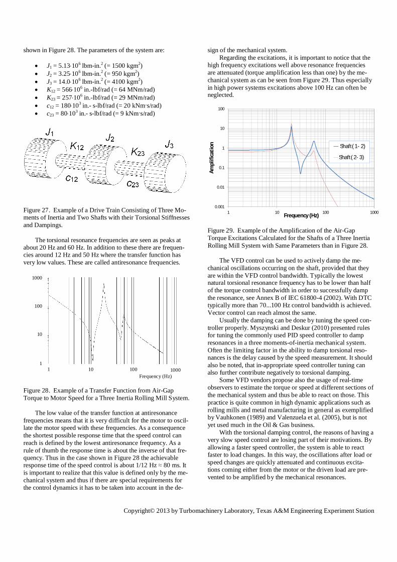
Copyrightcopy 2013 by Turbomachinery Laboratory Texas AampM Engineering Experiment Station
Design Principles
Above considerations result in the following best practices
- Tune the process control in such a way that it is slowerthan the speed control
- Have the speed control tuned to be slower than the VFDtorque control This assumes big importance especially inbig LNG trains
- Make sure that the speed reference or torque referencegiven by the process control is free of noise and other in-terfering signals because these will be reproduced in themotor torque and may excite mechanical resonances
- Make sure that the speed sensor is properly installed Forexample eccentric mounting causes erroneous shaft rota-tion frequency component in the measured speed
- Further make sure that lateral vibrations of the motor arenot affecting the speed sensor operation Any erroneousfluctuation in the measured signal may become amplifiedin the speed control and excite torsional resonances It isnaturally possible to attenuate this kind of interfering sig-nals by filtering but then it may be impossible to use thespeed control to damp resonances
- Sometimes problems with speed sensors can be avoidedby using the VFD in torque controlled mode and integrat-ing the drive directly in the process control The VFD canstill be used for speed monitoring and fast protection
SHORT CIRCUIT LOADING WITH VFDs
If a direct-on-line connected AC machine is short-circuited it will produce high torques at the line frequency andtwice-line frequency Short circuits frequently occur in the supply network Thusit has been the practice to avoid mechanical resonance frequen-cies at these frequencies when the motor is directly fed from thesupply grid However when the motor is supplied with a fre-quency converter its input frequency will vary and it may notbe possible to keep mechanical resonances outside the frequen-cy range of continuous operation Luckily the short circuiting of converter fed motors is veryrare because the converter isolates the motor when there is afault in the supply network Design principles have been dealtwith in detail in the paper by Grgic et al (1992) Usually shortcircuits are considered not to pose any significant threat to themechanical system when frequency converters are used
CONCLUSIONS
This paper presented the modeling analysis and design ofelectric drives as a part of torsional systems The subject wasreviewed from a broad perspective aiming to serve rotordynam-ic professionals with background outside of electric drives Theanalysis and design guidelines were proposed throughout thepaper As a conclusion the main points are repeated here
One of the important observations is that only the couplingmode and to some extent modes with their oscillation nodewithin the driven equipment are prone to electromagnetic exci-tations The high-frequency excitations cancel effectively out
due to the shape of the higher modes within the electric motorThe second observation is that the electromechanical inter-
action ie electromagnetic stiffness and damping may affectsignificantly the coupling mode and its damping ratio if theload inertia is large compared to the motor inertia
The third observation is that the dimensioning torque isusually the short-circuit torque The transient air-gap torque ofthis fault can be easily calculated The corresponding shaft-endtorque is determined by the inertia ratio and the frequency ratioThe inertia ratio is determined by the application and cannot beeasily changed By decreasing the frequency ratio ie the fre-quency of the coupling mode divided by the supply frequencythe shaft end loading can be decreased significantly
Variable frequency drives bring considerable advantagesfrom a process control point of view In addition they improvethe conditions for the motor and drive-train during starting andare able to protect the torsional system from disturbances in thegrid such as unbalances and short circuits However due totheir inherent operating principle the torque provided by varia-ble frequency drives contains harmonics which need to be takeninto account during the system design of drive-trains especiallyfor high power systems
Some variable frequency drives modulation schemes pro-duce torques with distinct excitation frequencies while othersproduce a spectrum which is a continuous function similar toacoustic white noise In both cases the designer of the shaftline shall take into account the data of excitation frequenciesand amplitudes of the converter driven motor and use them tofeed the torsional mode shapes of the mechanical system Do-ing so one has to keep in mind that closed-loop control canchange the torsional damping of the rotating equipment Thiscan be used to actively damp torsional resonances howeversimilarly unintentional negative damping needs to be avoidedby choosing control parameters accordingly
For very demanding applications especially in the high-speed-high-power range closed loop electromechanical simula-tions may bring additional confidence in the system design asthey consider nonlinearities of electric magnetic and mechani-cal components
The different possibilities to study the design leave the sys-tem integrator with the challenge to identify the appropriatelevel of detail which he needs to successfully design his sys-tem He will have to revert to the component suppliers not leastthe drives and motor supplier in order to get the necessary sup-port in this decision making process and then later the requiredinput data to his design
NOMENCLATURE
scA = Factor for short-circuit loading
12B = Viscous damping coefficientD = DiameterG = Shear modulusI = Current
1I = Motor mass-moment of inertia
2I = Load-machine mass-moment of inertia
12K = Torsional stiffness coefficientL = Shaft section length
Copyrightcopy 2013 by Turbomachinery Laboratory Texas AampM Engineering Experiment Station
P = PowerT = Torque
scT = Short-circuit torque
0T = Rated torque
1T = Air-gap torque
12T = Shaft-end torque
T = Maximum amplitude of torque TU = Voltage
excf = Excitation frequency
linef = Grid frequency 50 Hz or 60 Hz
resf = Torsional resonance frequency
1f = Motor supply frequency output frequency of theinverter
k = Torsional stiffness integer multiplier for inverter frequencyn = Speed
1n = Synchronous rotational speedm = integer multiplier for grid frequencyp = Number of pole-pairs of the motors = Slip of the rotorz = Damping ratioh = Efficiencyt = Frequency ratio
jcos = Power factorY = Angle of twist
1w = Motor supply frequency in radians
AC = Alternating currentAFD = Adjustable frequency driveASD = Adjustable speed driveCHB = Cascaded H-bridgeCSI = Current source inverterDC = Direct currentDOL = Direct on lineDTC = Direct torque controlFEM = Finite element methodGTO = Gate turn-offIGBT = Insulated gate bipolar transistorIGCT = Integrated gate controlled thyristorLCI = Load commutated inverterNPC = Neutral point clampedNPP = Neutral point pilotedPI = Proportional-integralPWM = Pulse width modulationSCR = Silicon controlled rectifierVFD = Variable frequency driveVSDS = Variable speed drive systemVSI = Voltage source inverter
REFERENCES
ANSI C5041 2000 ldquoPolyphase Induction Motors for PowerGenerating Stationsrdquo American National Standards
API 541 2004 ldquoForm-wound Squirrel-Cage Induction Motors
ndash 500 Horsepower and Largerrdquo Fourth Edition AmericanPetroleum Institute Washington DC
API 546 2008 ldquoBrushless Synchronous Machines ndash 500 kVAand Largerrdquo Third Edition American Petroleum InstituteWashington DC
API 684 2005 ldquoAPI Standard Paragraphs - Rotordynamic Tu-torial Lateral Critical Speeds Unbalance Response Stabil-ity Train Torsionals and Rotor Balancingrdquo Second Edi-tion American Petroleum Institute Washington DC
Barnes M (2003) Practical Variable Speed Drives and PowerElectronics Oxford UK Newnes
Corbo M A and Malanoski S B 1996 ldquoPractical DesignAgainst Torsional Vibrationrdquo Proceedings of the Twenty-Fifth Turbomachinery Symposium Turbomachinery Labor-atory Texas AampM University College Station Texas pp189-222
Corbo M A Cook C P Yeiser C W and Costello M J2002 ldquoTorsional Vibration Analysis and Testing of Syn-chronous Motor-Driven Turbomachineryrdquo Proceedings ofthe Thirty-First Turbomachinery Symposium Tur-bomachinery Laboratory Texas AampM University CollegeStation Texas pp 153-175
DIN 4024 1988 ldquoMachine Foundations ndash Flexible Structuresthat Support Machines with Rotating Elementsrdquo DeutscheNorm
Ehrich F F (ed) 2004 Handbook of Rotordynamics Mala-bar Florida Krieger
Fitzgerald A E Kingsley C and Umans S 2003 ElectricMachinery (6th ed) New York New York McGraw-Hill
Garvey S D Penny J E T Friswell M I and Lees A W2004 ldquoThe Stiffening Effect of Laminated Rotor Cores onFlexible-Rotor Electrical Machinesrdquo Proceedings of theEighth International Conference on Vibrations in RotatingMachinery Professional Engineering Publishing SuffolkUK pp 193-202
Grgic A Heil W and Prenner H 1992 ldquoLarge Converter-fed Adjustable Speed AC drives for Turbomachinesrdquo Pro-ceedings of the Twenty-First Turbomachinery SymposiumTurbomachinery Laboratory Texas AampM University Col-lege Station Texas pp 103-112
Holopainen T P and Arkkio A 2008 ldquoElectromechanicalInteraction in Rotordynamics of Electrical Machines ndash anOverviewrdquo Proceedings of the Ninth International Con-ference on Vibrations in Rotating Machinery Chandospublishing Oxford UK Vol 1 pp 423 ndash 436
Holopainen T P Repo A-K and Jaumlrvinen J 2010 ldquoElec-tromechanical Interaction in Torsional Vibrations of DriveTrain Systems Including an Electrical Machinerdquo Proceed-
Copyrightcopy 2013 by Turbomachinery Laboratory Texas AampM Engineering Experiment Station
ings of the Eighth International Conference on Rotor Dy-namics Korea Institute of Science amp Technology SeoulKorea 8 p
Hudson J 1992 ldquoLateral Vibration Created by TorsionalCoupling of a Centrifugal Compressor System Driven by aCurrent Source Drive for a Variable Speed Induction Mo-torrdquo Proceedings of the Twenty-First TurbomachinerySymposium Turbomachinery Laboratory Texas AampMUniversity College Station Texas pp 113 ndash 124
Hudson J 1996 ldquoSelection Design and Field Testing of a10500 Horsepower Variable Speed Induction Motor Com-pressor Driverdquo Proceedings of the Twenty-Fifth Tur-bomachinery Symposium Turbomachinery LaboratoryTexas AampM University College Station Texas pp 25 ndash34
IEC 61800-4 2002 ldquoAdjustable Speed Electrical Power DriveSystems Part 4 General Requirements - Rating Specifica-tions for AC Power Drive Systems Above 1000 V ACand not Exceeding 35 kVrdquo
Kazmierkowski M P Franquelo L Rodriguetz J Perez Mand Leon J 2011 High Performance Motor DrivesIEEE Industrial Electronics Magazine 5 pp 6ndash26
Kocur J and Muench M 2011 ldquoImpact of Electrical Noiseon the Torsional Response of VFD Compressor TrainsrdquoProceedings of the First Middle East TurbomachinerySymposium Doha Qatar 8 p
Myszynski R and Deskur J 2010 ldquoDamping of TorsionalVibrations in High-Dynamic Industrial Drivesrdquo IEEETransactions on Industrial Electronics 2 pp 544-552
NEMA MG 1-2003 ldquoMotors and Generatorsrdquo National Elec-trical Manufacturers Association Rosslyn Virginia
Pilkey W D 1994 Stress Strain and Structural MatricesNew York New York John Wiley amp Sons
Tripp H Kim D and Whitney R 1993 ldquoA ComprehensiveCause Analysis of a Coupling Failure Induced by TorsionalOscillations in a Variable Speed Motorrdquo Proceedings ofthe Twenty-Second Turbomachinery Symposium Tur-bomachinery Laboratory Texas AampM University CollegeStation Texas pp 17 ndash 24
Valenzuela A Bentley J Villablanca A and Lorentz R2005 ldquoDynamic Compensation of Torsional Oscillation inPaper Machine Sectionsrdquo IEEE Transactions on IndustryApplications 6 pp 1458-1466
Vauhkonen V 1989 ldquoA Fast-Response State Observer in anElectro-Mechanical Drive Systemrdquo Saumlhkouml 3 pp 24-28
Wachel J C and Szenasi F R 1993 ldquoAnalysis of TorsionalVibrations in Rotating Machineryrdquo Proceedings of theTwenty-Second Turbomachinery Symposium Tur-
bomachinery Laboratory Texas AampM University CollegeStation Texas pp 127 ndash 151
Wilson W K 1956 Practical Solution of Torsional VibrationProblems New York New York John Wiley amp Sons
ACKNOWLEDGEMENTS
The authors gratefully acknowledge the valuable sugges-tions and support of Juhani Mantere ABB Motors and Genera-tors Special thanks are due to Mark A Corbo No Bull Engi-neering for valuable discussions and feedback related to varia-ble frequency drives
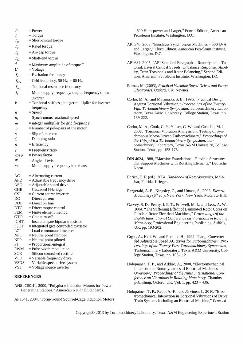
Copyrightcopy 2013 by Turbomachinery Laboratory Texas AampM Engineering Experiment Station
ings of the Eighth International Conference on Rotor Dy-namics Korea Institute of Science amp Technology SeoulKorea 8 p
Hudson J 1992 ldquoLateral Vibration Created by TorsionalCoupling of a Centrifugal Compressor System Driven by aCurrent Source Drive for a Variable Speed Induction Mo-torrdquo Proceedings of the Twenty-First TurbomachinerySymposium Turbomachinery Laboratory Texas AampMUniversity College Station Texas pp 113 ndash 124
Hudson J 1996 ldquoSelection Design and Field Testing of a10500 Horsepower Variable Speed Induction Motor Com-pressor Driverdquo Proceedings of the Twenty-Fifth Tur-bomachinery Symposium Turbomachinery LaboratoryTexas AampM University College Station Texas pp 25 ndash34
IEC 61800-4 2002 ldquoAdjustable Speed Electrical Power DriveSystems Part 4 General Requirements - Rating Specifica-tions for AC Power Drive Systems Above 1000 V ACand not Exceeding 35 kVrdquo
Kazmierkowski M P Franquelo L Rodriguetz J Perez Mand Leon J 2011 High Performance Motor DrivesIEEE Industrial Electronics Magazine 5 pp 6ndash26
Kocur J and Muench M 2011 ldquoImpact of Electrical Noiseon the Torsional Response of VFD Compressor TrainsrdquoProceedings of the First Middle East TurbomachinerySymposium Doha Qatar 8 p
Myszynski R and Deskur J 2010 ldquoDamping of TorsionalVibrations in High-Dynamic Industrial Drivesrdquo IEEETransactions on Industrial Electronics 2 pp 544-552
NEMA MG 1-2003 ldquoMotors and Generatorsrdquo National Elec-trical Manufacturers Association Rosslyn Virginia
Pilkey W D 1994 Stress Strain and Structural MatricesNew York New York John Wiley amp Sons
Tripp H Kim D and Whitney R 1993 ldquoA ComprehensiveCause Analysis of a Coupling Failure Induced by TorsionalOscillations in a Variable Speed Motorrdquo Proceedings ofthe Twenty-Second Turbomachinery Symposium Tur-bomachinery Laboratory Texas AampM University CollegeStation Texas pp 17 ndash 24
Valenzuela A Bentley J Villablanca A and Lorentz R2005 ldquoDynamic Compensation of Torsional Oscillation inPaper Machine Sectionsrdquo IEEE Transactions on IndustryApplications 6 pp 1458-1466
Vauhkonen V 1989 ldquoA Fast-Response State Observer in anElectro-Mechanical Drive Systemrdquo Saumlhkouml 3 pp 24-28
Wachel J C and Szenasi F R 1993 ldquoAnalysis of TorsionalVibrations in Rotating Machineryrdquo Proceedings of theTwenty-Second Turbomachinery Symposium Tur-
bomachinery Laboratory Texas AampM University CollegeStation Texas pp 127 ndash 151
Wilson W K 1956 Practical Solution of Torsional VibrationProblems New York New York John Wiley amp Sons
ACKNOWLEDGEMENTS
The authors gratefully acknowledge the valuable sugges-tions and support of Juhani Mantere ABB Motors and Genera-tors Special thanks are due to Mark A Corbo No Bull Engi-neering for valuable discussions and feedback related to varia-ble frequency drives