tvs 31-01 - rf-tuote.fi · tvs 31-01 adjustable matv amplifier user manual . ... • the one-rotary...
TRANSCRIPT

RF-Tuote Oy, Joensuunkatu 13, 24100 Salo, Finland, tel. +358-2-736 6360, fax. +358-2-736 6355, [email protected], www.rf-tuote.fi
TVS 31-01
Adjustable MATV amplifier
User Manual
RF-Tuote Oy, Joensuunkatu 13, 24100 Salo, Finland, tel. +358-2-736 6360, fax. +358-2-736 6355, [email protected], www.rf-tuote.fi
1. Purpose of use
TVS 31-01 amplifier is designed for use in antenna systems receiving terrestrial analogue and digital HD programs in detached houses, residences, terrace houses, hotels, boarding houses, holiday centers, schools, hospitals, etc. - even situated in places with difficult reception conditions, where the received signals have different levels and are coming from different directions. TVS 31-01 enables to receive signals, to equalize levels and to amplify. TVS 31-01 is supplied with 4G LTE filters. The amplifier can be used as an independent unit, as well as a part of a bigger head-end station.
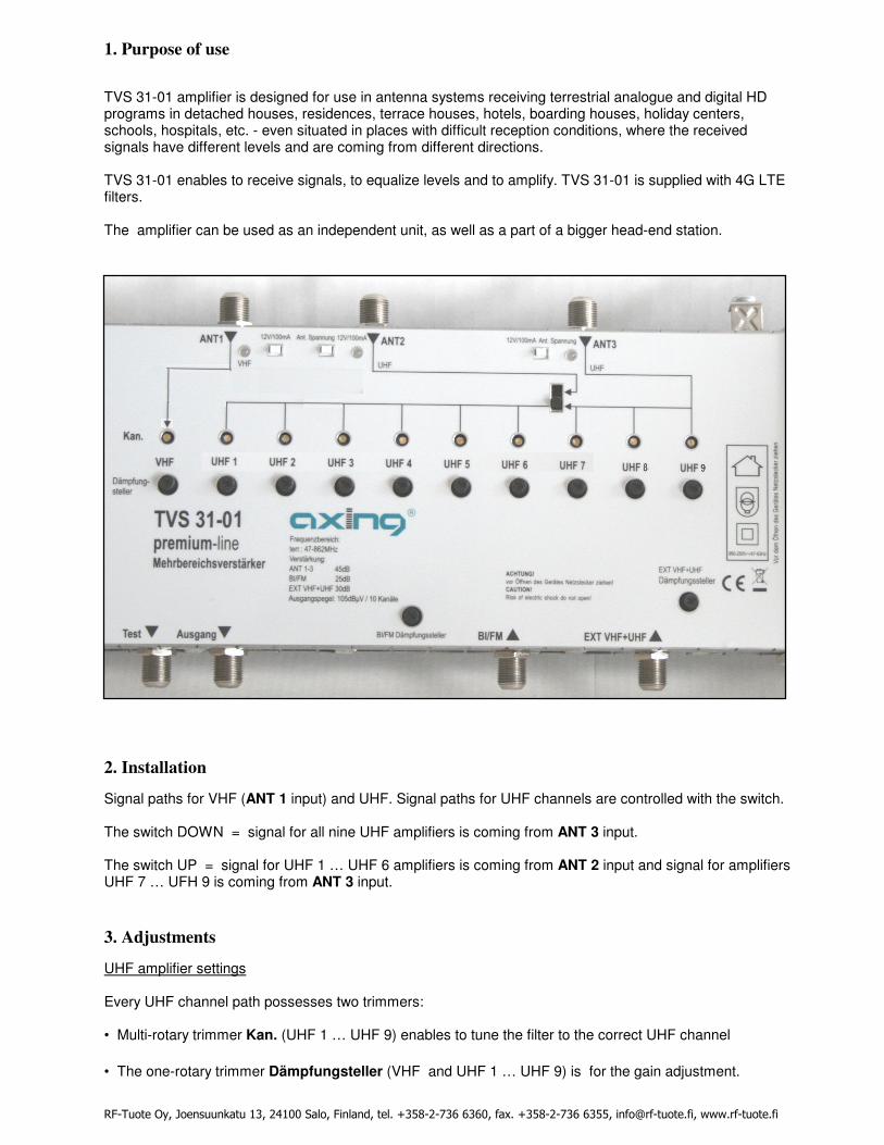
2. Installation
Signal paths for VHF (ANT 1 input) and UHF. Signal paths for UHF channels are controlled with the switch. The switch DOWN = signal for all nine UHF amplifiers is coming from ANT 3 input. The switch UP = signal for UHF 1 … UHF 6 amplifiers is coming from ANT 2 input and signal for amplifiers UHF 7 … UFH 9 is coming from ANT 3 input.
3. Adjustments
UHF amplifier settings Every UHF channel path possesses two trimmers: • Multi-rotary trimmer Kan. (UHF 1 … UHF 9) enables to tune the filter to the correct UHF channel
• The one-rotary trimmer Dämpfungsteller (VHF and UHF 1 … UHF 9) is for the gain adjustment.
RF-Tuote Oy, Joensuunkatu 13, 24100 Salo, Finland, tel. +358-2-736 6360, fax. +358-2-736 6355, [email protected], www.rf-tuote.fi
1. Set ”Kan UHF 1… UHF 9 “ trimmers in the right final position. 2. Set “Dämpfungsteller” trimmer in the middle position. 3. Connect mains plug to the power outlet. 4. Connect the level meter to the amplifier output. 5. Select the right channel number on the level meter. 6. Select the trimmer respondent the chosen channel number and turning it in left, get the maximum value on the level meter. NOTE! Adjacent channels are recommend to adjust for parallel signal paths. 7. Using the gain trimmer set the required signal level. 8. Repeat steps from point 5 to 7 until all VHF and UHF channels are assigned to channel paths. FM band Set BI/FM band amplifier to required level with B1/FM trimmer. Connecting of additional devices Additional devices (video recorder, PC, camera with A/V modulator, etc.) can be connected after switching off the amplifier. For this purpose EXT VHF + UHF input should be used. Signal level can be adjusted by EXT VHF+UHF attenuator. Mast amplifier can be powered (max. 12 VDC/80 mA) by pressing Ant. Spennung switch down. 3. Technical Specifications
RF Inputs BI / FM VHF UHF1/UHF2 EXT VHF+UHF Frequency range MHz 47-108 174-230 470-790 174-860 Gain dB 25 ±2 45+3 45 ±3 30 ±2 Gain regulation dB 0-20 0-20 0-20 0-20 Channel paths selectivity dB ≥ 20 ±20MHz Max input level dBuV 100 75 75 85 Min input level: for S/N > 30dB 35 35 37 for S/N > 45dB dBuVdBuV 50 50 52 Isolation between inputs: UHF-UHF dB >26 BI/FM/VHF-UHF dB >26 Max output signal level for 10 TV signals (DIN 45004B -60dB) dBuV 105 Input/Output impedance Ω 75 / 75 GENERAL Preamplifiers power supply V DC / mA 12/ 80 Status indicator of preamplifier LED diode:– green color Work temperature range °C -10….+50 Power supply V AC / Hz 230 / 50-60 Power consumption VA 12 Dimensions mm 354 x 113 x 75 Weight kg 0,9